


Overview
This post is all about Laser Light Security System using 555 Timer IC & LDR. In today’s world, safety and security are of paramount importance for both homes and businesses. To that end, we present an exciting and cost-effective DIY project: the Laser Light Security System. This project utilizes a simple yet effective combination of a laser beam, an LDR (Light Dependent Resistor), a 555 timer IC, a relay, an LED, and a buzzer to create an intrusion detection solution.
When the laser beam is interrupted, the system triggers an alarm and activates an LED, alerting you to the possible presence of an intruder. Earlier we build the Laser Security System using Arduino & Laser diode.
Not only is this project easy to assemble and understand, but it also offers the opportunity to learn about basic electronic components, their functions, and how they interact with one another. Furthermore, this security system can be customized and scaled up to suit various applications, from securing a single doorway to covering multiple access points within a property.
Components Required
The following are the components required for this Laser Security System Project:

- 555 timer IC
- LDR (Light Dependent Resistor)
- 5V Relay
- LED (any color)
- Siren or buzzer
- A laser pointer or Laser Diode Module
- Resistors: 10K, 1K, 220E, 330E
- Potentiometer 10K
- Electrolytic Capacitor: 10uF
- Ceramic Capacitor: 0.1uF – 2
- Diode 1N4007
- Breadboard or PCB
- Jumper wires
- Power supply (5V-12V)
Circuit Diagram & Connections
Here is the schematic of the Laser Security System designed using 555 Timer IC & LDR.

Here we need to set up the 555 timer IC in monostable mode. Then by connecting the LDR and the potentiometer in a voltage divider configuration to trigger the 555 timer. Then we can use the output of the 555 timer to drive a relay, which in turn activates the siren/buzzer and an LED when the laser beam is interrupted.
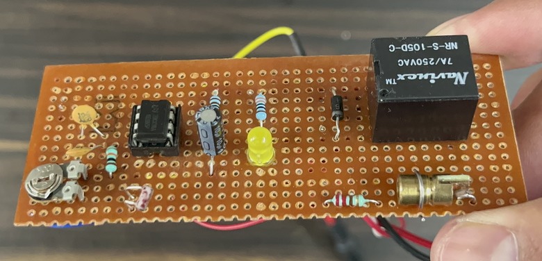
You can assemble the circuit in a Zero PCB Board.
Working of Laser Security System using 555 Timer IC & LDR
The laser light security system using 555 Timer operates by monitoring the presence of a continuous laser beam. At the heart of the circuit is a 555 timer IC, configured in monostable mode, which responds to changes in light levels detected by the Light Dependent Resistor (LDR). A laser pointer or laser diode module is used to provide a steady beam of light, which is aimed directly at the LDR. The LDR’s resistance varies according to the amount of light it receives. When the laser beam is uninterrupted, the LDR’s resistance is low.
A 10K potentiometer is connected in series with the LDR to form a voltage divider. This allows for adjusting the system’s sensitivity to changes in the LDR’s resistance. When the laser beam is interrupted, the LDR’s resistance increases, causing a change in the voltage at the trigger input (pin 2) of the 555 timer IC. This change in voltage initiates the monostable mode operation of the 555 timer, generating a pulse at its output (pin 3).

The output pulse from the 555 timer drives a relay through an NPN transistor. The relay, in turn, activates the alarm (siren/buzzer) and an LED, indicating that the laser beam has been broken. The relay remains energized for the duration of the output pulse, providing a clear indication of a security breach.
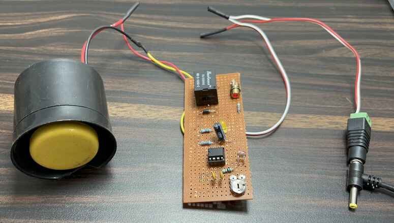
Testing & Demo
- Aim the laser pointer or laser diode module at the LDR, ensuring that the light falls directly on the LDR.
- Adjust the 10K potentiometer until the relay is off (LED and siren/buzzer are off) when the laser beam is incident on the LDR.
- When the laser beam is interrupted, the LDR’s resistance increases, triggering the 555 timer IC. This, in turn, activates the relay, LED, and siren/buzzer.

Note: Remember to always exercise caution when working with lasers, as they can cause eye damage. Use appropriate safety measures, such as laser safety goggles, and do not point the laser at people or animals.


")


