US8089630B2 - Spectral near-field optical tomography - Google Patents
Spectral near-field optical tomography Download PDFInfo
- Publication number
- US8089630B2 US8089630B2 US12/402,177 US40217709A US8089630B2 US 8089630 B2 US8089630 B2 US 8089630B2 US 40217709 A US40217709 A US 40217709A US 8089630 B2 US8089630 B2 US 8089630B2
- Authority
- US
- United States
- Prior art keywords
- illuminating
- accordance
- path
- aperture
- wavevectors
- Prior art date
- Legal status (The legal status is an assumption and is not a legal conclusion. Google has not performed a legal analysis and makes no representation as to the accuracy of the status listed.)
- Expired - Fee Related, expires
Links
Images


Classifications
-
- G—PHYSICS
- G01—MEASURING; TESTING
- G01N—INVESTIGATING OR ANALYSING MATERIALS BY DETERMINING THEIR CHEMICAL OR PHYSICAL PROPERTIES
- G01N21/00—Investigating or analysing materials by the use of optical means, i.e. using sub-millimetre waves, infrared, visible or ultraviolet light
- G01N21/17—Systems in which incident light is modified in accordance with the properties of the material investigated
- G01N21/47—Scattering, i.e. diffuse reflection
- G01N2021/4704—Angular selective
- G01N2021/4709—Backscatter
-
- G—PHYSICS
- G01—MEASURING; TESTING
- G01N—INVESTIGATING OR ANALYSING MATERIALS BY DETERMINING THEIR CHEMICAL OR PHYSICAL PROPERTIES
- G01N21/00—Investigating or analysing materials by the use of optical means, i.e. using sub-millimetre waves, infrared, visible or ultraviolet light
- G01N21/17—Systems in which incident light is modified in accordance with the properties of the material investigated
- G01N21/47—Scattering, i.e. diffuse reflection
- G01N2021/4704—Angular selective
- G01N2021/4711—Multiangle measurement
Definitions
- the present invention pertains to methods and apparatus for imaging in three dimensions with a resolution exceeding that corresponding to the wavelength of illuminating radiation.
- Electromagnetic radiation such as light
- Electromagnetic radiation is characterized by one or more frequencies and propagation directions, collectively constituting a “spectrum” of wavevectors associated with the radiation.
- aperture is any geometrical configuration giving rise to diffraction of radiation. It is to be understood that the term aperture does not require an actual physical opening, and that a sharp metal tip, for example, or a sharpened facet of an optical fiber, may serve as a pointlike secondary source that illuminates a sample and serves the function of an aperture for purposes of the present treatment. Further discussion of this point may be found in Sun et al., J. Appl. Phys ., vol. 102, art. no. 103103 (2007), which is incorporated herein by reference in its entirety.
- near field means a regime in which evanescent components of a scattering wavefunction are significant.
- Other regions of the field, more distant from the defining aperture, are referred to herein as the “far field.”
- NSM near-field scanning optical microscopy
- two-dimensional imaging is less than optimal since important information is contained in the structure of the sample in the depth dimension.
- NOT near-field scanning optical tomography
- Gaikovich Phys. Rev. Lett., vol. 98, art. no. 243901 183902 (2007), describes a microwave near-field tomography system where additional data are acquired by scanning the sample using probes of different sizes.
- additional near-field data may be collected using multiple observation angles, as described, for example, in Carney & Schotland (2003), op. cit.
- Embodiments of the present invention improve upon the prior art by allowing reconstruction of a three-dimensional object's physical characteristics by varying the wavelength of illuminating radiation emanating from a single subwavelength aperture.
- Subwavelength spatial resolution of the sample may be obtained without using multiple probe tips, multiple observation angles, or subwavelength coregistration of multiple two-dimensional images.
- a method for imaging an object has steps of:
- the information provided regarding a scattering characteristic of the object may be, specifically, in a direction along the illuminating path.
- the step of detecting may include disposing the detector in a far field, and the aperture may be a tip or other physical structure.
- the method for imaging an object may include further steps of:
- the method may also have steps of varying observing angles and of scanning the aperture to a plurality of positions in a plane substantially parallel to the surface of the object.
- Scanning the aperture may include scanning a position of a probe tip that is small on a scale of the characterizing wavelength of the illuminating electromagnetic wave.
- the method for imaging may also have a step of spectrally dispersing electromagnetic waves scattered by the object prior to detection by the detector.
- detection of electromagnetic waves scattered by the object may specifically include detecting a phase of the scattered electromagnetic waves.
- a computer program product for deriving an image of a physical object.
- the computer program product has a computer usable medium with:
- an apparatus in another embodiment, has an illumination source for illuminating the object with an illuminating electromagnetic wave via an illumination path, the illuminating electromagnetic wave being characterized by a spectrum of illuminating wavevectors.
- the apparatus also has a detector for detecting electromagnetic waves scattered by the object along a collection path, the scattered electromagnetic waves being characterized by a spectrum of detected wavevectors.
- the apparatus further has an aperature equal to or smaller than an instantaneous characterizing wavelength of an illuminating wavevector or a detected wavevector, the aperature being disposed within at least one of the illuminating path and the collection path.
- the apparatus has a processor capable of applying a forward model of the imaging system to derive a three-dimensional scattering model and inverting a detected data function in terms of the forward model to obtain a three-dimensional reconstruction of the object.
- the illumination source is a broadband source, such as a pulsed laser, the laser being tunable to vary the illuminating wavevectors.
- the processor may be capable of controlling the laser in addition to its other processing capabilities.
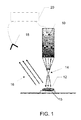
- FIG. 1 is a schematic depiction of an implementation of a sub-wavelength near-field imaging system in accordance with an embodiment of the present invention
- FIG. 2 is a flow chart depicting process steps for sub-wavelength imaging in accordance with embodiments of the present invention
- FIGS. 3( a - e ) represent reconstructions for the many-angle NSOT systems, but at a solitary wavelength ⁇ .
- the other simulations of FIG. 3 correspond to broadband reconstructions in accordance with embodiments of the present invention:
- FIGS. 3( f - j ) show reconstructions for single-angle broadband NSOT systems, while FIGS. 3( k - o ) show reconstructions for two-angle broadband NSOT systems.
- FIGS. 3( a ), 3 ( f ) and 3 ( k ) show the x-z plane while the remaining plots give x-y detail.
- the axes used for FIG. 3( a - e ) are repeated in FIGS. 3( f - j ) and FIGS. 3( k - o );
- FIG. 4 is a sample object used in the simulation of FIGS. 5( a - b ) and 6 ( a - b ), with the vertical axis representing distance from the scan plane in the z direction;
- FIGS. 5( a - b ) show tomographic reconstructions of the sample under different numbers of incident angles and bandwidth; ⁇ k is the bandwidth in the spatial frequency of the incident field; N i is the number of angles of incidence, which were spaced in such a way that projections of the incident wave vectors onto the normal (z) direction of the interface do not overlap; and
- N spatial dimensions by collecting data in (N ⁇ 1) spatial dimensions and a spectral dimension
- spectral dimension has found application in conventional far-field techniques such as optical coherence tomography, described by Schmitt, IEEE J. Sel. Top. in Quant. Electronics , vol. 5, p.
- the NSOT probe is assumed to behave as a point source illuminating the sample.
- Illumination source 10 may emit a narrow band of wavelengths that are varied or tuned.
- a tunable laser serves such a purpose.
- source 10 may be a broadband source, which may further include passive or active spectral filtering.
- Object 12 is located in the near field of an aperture 14 , which may be an actual opening or a probe region, small on the scale of the pertinent wavelength, from which the incident beam is reflected or scattered.
- Aperture 14 is situated such that object 12 lies within the near field of light emanating from the aperture.
- process 24 light 16 scattered from the object is detected by one or more detectors 18 disposed in the far field with respect to the light from aperture 14 that is scattered by object 12 .
- process 26 the position of aperture 14 relative to the surface of object 12 is scanned in a direction that is locally substantially parallel to the surface of object 12 , such that the illumination intercepts successive regions of the object.
- the scan may be accomplished using a scanner 15 .
- the scanner may be any positioner or actuator known in the art to be useful for this purpose.
- the spectrum of the illuminating light which may be narrow-band or broadband, within the scope of the present invention, may also be varied as a function of time, in process 28 .
- Controller 20 which may include a computer processor, governs operation of source 10 , scanning the wavelength of the source, and receives a signal from detector 18 for processing, as described herein.
- the resulting scattered light is then collected coherently as a function of angle and/or wavelength depending on the NSOT modality considered.
- a forward scattering model is applied to the gathered data, as described in the following.
- a weakly scattering sample described by the dielectric susceptibility ⁇ (r)
- ⁇ (r) is placed in vacuum above a half-space with a uniform index of refraction n.
- the tip 14 is scanned over the sample while the system is illuminated by an incident plane wave E i .
- k
- the projection of the wave vector onto the z axis is given by
- Eq. (3) describes light originating from a point source at r, scattering from all sample positions r′ and propagating to r d .
- the NSOT system is described in illumination mode but the theory may be equally applied to detection mode, within the scope of the present invention, by considering a source at r d and a point detector at r. It is also implicit that the probe does not strongly interact with the sample—an approximation investigated in Sun et al., (2007).
- the Fourier-domain model expressed in Eq. (8) implicitly assumes an infinite and continuous scan range, as the continuous, infinite-limit Fourier transform is employed in the derivation.
- a finite and discrete sampling grid approximates Eq. (8), provided that the probe scanning step is sufficiently small to preclude aliasing and the scan range covers all significant signal.
- the Green's tensor is conveniently expressed in a plane wave decomposition as
- G ⁇ ( r , r ′ , k ) i 2 ⁇ ⁇ ⁇ ⁇ d 2 ⁇ qg ⁇ ( z , z ′ , k ; q ) ⁇ exp ⁇ [ i ⁇ q ⁇ ( ⁇ - ⁇ ′ ) ] , ( 12 )
- g(z,z′; q) the plane wave component
- g ⁇ ( z , z ′ , k ; q ) 1 k z ⁇ ( q , k ) ⁇ ⁇ [ ?? ⁇ ( q ) ⁇ e i ⁇ ⁇ k z ⁇ ( q , k ) ⁇ ( z - z ′ ) + R ⁇ ( q ) ⁇ e i ⁇ ⁇ k z ⁇ ( q , k ) ⁇ ( z + z ′ ) ] 0 ⁇ z ′ ⁇ z [ ??
- a TS ⁇ ( r t , k d ) k 4 ⁇ ⁇ d 3 ⁇ r ′ ⁇ e - i ⁇ ⁇ k d ⁇ ( r t + r ′ ) ⁇ p ⁇ [ ??
- Equation (23) is the block-diagonalized forward integral equation, and is more suitable for a numerical inversion than Eq. (16). Inversion
- the operator A q maps a continuous function on z to data collected on a discrete set ⁇ of k vectors.
- the SVD analysis of such semi-discrete systems is standard and will be used, without limitation and for purposes of the current description, to invert the mapping from z to ⁇ .
- the Gram matrix for A q defines a normal operator ⁇ M q (k,k′), ⁇ > k′ which effects a matrix multiplication in k space.
- the Gram matrix is
- the real nonnegative eigenvalues of M q and the corresponding eigenvectors are found numerically.
- the l th eigenvector c q l (k) (where the measurement wavevector k indexes the vector element) is the l th left-singular vector of A q , and the square root of the l th eigenvalue of M q is the singular value ⁇ q l .
- the preprocessed data q can then be used in the inversion of Eq. (25).
- the truncated singular value decomposition (TSVD) is employed to find ⁇ tilde over (V) ⁇ q + (z), an estimate of the sample in q-z space.
- TSVD is used to provide stability to noise and is expressed as
- N + is the number of singular components d in the reconstruction.
- the regularization of the inverse problem is controlled by N + —a greater N + gives better reconstruction fidelity while a lesser N + reduces sensitivity to measurement noise.
- the performance of the broadband and/or multi-angle NSOT systems was investigated using numerical simulations and the scalar forward model and inversion paradigms.
- Synthetic data were generated by defining a test sample V(r) and evaluating Eq. (3) for the modality considered.
- the sample consisted of four point scatterers at ( ⁇ 3, 0, ⁇ 0.15) ⁇ , ( ⁇ 1.5, 0, ⁇ 0.35) ⁇ , (0, 0, ⁇ 0.55) ⁇ and (1.5, 0, ⁇ 0.75) ⁇ , where ⁇ is a nominal wavelength.
- the first scatterer had a scattering potential 80% lower than the other scatterers in order to give a reconstruction with comparable peak amplitudes.
- the sample is assumed to lie in the region ⁇ z ⁇ 0.1 ⁇ .
- NSOT systems Three NSOT systems were considered: the first is a single wavelength ( ⁇ ), many-angle system, as discussed in Carney et al. (2000), with k lying in the x-z plane and having 32 observation angles evenly spaced across a semicircle; the second system has a single observation angle (k lies in the x-z plane at 45° from vertical) and 32 observation wavelengths between 0.8 ⁇ and 1.2 ⁇ ; and the third system has the same spectral range as the second but with two observation angles (30° and 60° from vertical in the x-y plane) and 16 spectral samples per observation angle. All three systems have a scan step of ⁇ /12 in both x and y, with 100 and 80 samples in the x and y directions respectively.
- FIG. 3 From FIG. 3 it can be seen that the resolution for the broadband ( FIGS. 3( a - e )) and limited observation angle ( FIGS. 3( f - j )) NSOT systems is poorer than for the many-angle case, but meaningful three-dimensional detail is given. In all systems the resolution degrades with depth into the sample. Due to asymmetry in the observation angles, the many-angle and two-angle NSOT systems have differing resolutions in the x and y directions.
- ⁇ ⁇ Q + ⁇ ( z ) ⁇ k d , k d ′ ⁇ L Q * ⁇ ( z , k d ) ⁇ M Q + ⁇ ( k d , k d ′ ) ⁇ ⁇ ⁇ Q ⁇ ( k d ′ ) , ( 36 )
- M Q + is the regularized pseudo-inverse of the Gram matrix
- ⁇ tilde over ( ⁇ ) ⁇ Q ( k′ d ) k z ( q′ d +q t ,k ) ⁇ ( q′ t ,z t ,k′ d ) (37) is the pre-processed data.
- Regularization of the Gram matrix inversion may be trivially modified to achieve same effects as regularizing inversion of the forward operator.
- the corresponding object reconstruction may be obtained through a two-dimensional inverse Fourier transform, usually realized by a fast Fourier transform (FFT) algorithm.
- FFT fast Fourier transform
- FIGS. 6( a - b ) the reconstructions are shown in the three horizontal layers where the point scatterers are located. These reconstructions are produced individually, with different regularization for different layers. As a result, different layers are not comparable, in contrast to those shown in FIGS. 5( a - b ). Reconstruction thus produced are less noisy and quality is less sensitive to number of illumination angles and bandwidth compared to the previous case. As a tradeoff, these images may not be regarded as a tomography of the sample, they should rather be viewed as a computational re-focusing of the scattered near field for a fixed depth in the sample.
- the invention may be embodied in any number of instrument modalities, such as illuminating-probe, collecting-probe, multiple probes, etc., all within the scope of the invention.
- instrument modalities such as illuminating-probe, collecting-probe, multiple probes, etc.
- the “aperture” or “probe” may be more complex than a single point, and that the extension to a more complex analysis is within the scope of the present invention.
- the disclosed methods of near-field imaging may be implemented as a computer program product for use with a computer system.
- Such implementations may include a series of computer instructions fixed either on a tangible medium, such as a computer readable medium (e.g., a diskette, CD-ROM, ROM, or fixed disk) or transmittable to a computer system, via a modem or other interface device, such as a communications adapter connected to a network over a medium.
- the medium may be either a tangible medium (e.g., optical or analog communications lines) or a medium implemented with wireless techniques (e.g., microwave, infrared or other transmission techniques).
- the series of computer instructions embodies all or part of the functionality previously described herein with respect to the system. Those skilled in the art should appreciate that such computer instructions can be written in a number of programming languages for use with many computer architectures or operating systems.
- Such instructions may be stored in any memory device, such as semiconductor, magnetic, optical or other memory devices, and may be transmitted using any communications technology, such as optical, infrared, microwave, or other transmission technologies.
- a computer program product may be distributed as a removable medium with accompanying printed or electronic documentation (e.g., shrink wrapped software), preloaded with a computer system (e.g., on system ROM or fixed disk), or distributed from a server or electronic bulletin board over the network (e.g., the Internet or World Wide Web).
- some embodiments of the invention may be implemented as a combination of both software (e.g., a computer program product) and hardware. Still other embodiments of the invention are implemented as entirely hardware, or entirely software (e.g., a computer program product). All such variations and modifications are within the scope of the present invention as defined in any appended claims.
Abstract
Description
-
- a. illuminating the object with an illuminating electromagnetic wave via an illumination path, wherein the illuminating electromagnetic wave is characterized by a spectrum of illuminating wavevectors;
- b. detecting electromagnetic waves scattered by the object via a collection path, wherein the detector is characterized by a spectrum of detected wavevectors; wherein an aperture, disposed within at least one of the illuminating path and collection path, is equal to, or smaller than, an instantaneous characterizing wavelength of the electromagnetic wave; and
- c. varying the magnitude of at least one of the illuminating wavevectors and detected wavevectors in such a manner as to provide information regarding a scattering characteristic of the object.
-
- d. applying a forward model of the imaging system in a manner as to derive a three-dimensional scattering model; and
- e. inverting a detected data function in terms of the forward model to obtain a three-dimensional reconstruction of the object.
The forward model may be expressed in terms of a block-diagonalized forward integral equation, for example. The step of illuminating the object may include illumination by means of a broadband source, and the broadband source may be a pulsed laser. The step of illuminating the object may also include scanning a wavelength of a substantially monochromatic source.
-
- a. program code for generating a forward scattering model that includes variation of a magnitude of an illuminating wavevector and interposition of an aperture in an illuminating path or a collection path;
- b. program code for receiving a signal based on detection of scattering from the physical object; and
- c. program code for deriving a scattering characteristic of the physical object based on comparison with the forward scattering model of detected scattering from the object.
Moreover, the computer program product may also have: - d. program code for applying a forward model of the imaging system in a manner as to derive a three-dimensional scattering model; and
- e. program code for inverting a detected data function in terms of the forward model to obtain a three-dimensional reconstruction of the object.
E i(r,k d)=[I+
where
U(r,r d ,k)=∫d 3 r′G(r,r′,k)G(r′,r d ,k)V(r′), (3)
where r is the position of the probe, r′ is a dummy variable describing the scattering position within the sample, rd is the detector position, k is the wavenumber and the Green's function is G(r,r′,k)=eik|r′−r|/|r′−r|. Eq. (3) describes light originating from a point source at r, scattering from all sample positions r′ and propagating to rd. Here the NSOT system is described in illumination mode but the theory may be equally applied to detection mode, within the scope of the present invention, by considering a source at rd and a point detector at r. It is also implicit that the probe does not strongly interact with the sample—an approximation investigated in Sun et al., (2007).
U(r,k)=∫d 3 r′G(r,r′,k)e −ik·r′ V(r′). (4)
where r=(ρ,z) and kz(q,k)=√{square root over (k2−q2)} (with the principal branch used to evaluate this square root).
Taking the transform with respect to the scan dimensions ρ,
where {tilde over ( )} represents a transverse Fourier transform. The transverse Fourier transform contained in the remaining integral can also be evaluated by defining {tilde over (V)}, the two-dimensional transverse Fourier transform of V. The observation model now simplifies to a one-dimensional integral equation,
where k=[k∥,kz(k∥,k)]. This model applies to multi-angle and/or broadband NSOM. The dependence on both angle and wavelength is contained in k.
E s =p·[TS+ST]·E i, (9)
where T and S represent integral operators mapping a field incident on the tip or the sample to the respective scattered field. They are given by
[S·E](r)=k 2 ∫d 3 r′G(r,r′,k)η(r′)E(r′), (10)
and
[T·E](r)=k 2 ∫d 3 r′G(r,r′,k)αeδ(r′−r t)E(r′), (11)
where rt=(ρt,zt) is the position of the tip, G is the half-space Green's tensor, and αe is the polarizability used in the point model of the tip. It may be noted that while the scattering from the tip is exactly described by T, the scattering from the sample, described by S, is of first-Born type.
where g(z,z′; q), the plane wave component, is given by
where dependence on the wave number k of the polarization tensors
with the observation point rd in the far field in the upper half space and the source point r′ near the origin in the upper half space. Making use of Eqs (10), (11), (14), it is seen that the scattered field given by Eq. (9) can be represented by the scattering amplitude A=ATS+AST, i.e.,
where
Note that p represents certain TEM polarization in the propagation direction defined by kd, and therefore lies in the invariant subspace of the polarization operator
p·
and
G(r′,r t ,k)=G T(r t ,r′,k), (20)
it may be seen that AST=AT T S=ATS since ATS is a scalar quantity. Hence the scattered field may be represented by its amplitude A(rt,kd)=2ATS(rt,kd).
where the sum over ρt is carried out over all lattice vectors and qt belongs to the first Brillouin zone (FBZ) of the lattice. In this case FBZ=[−π/h,π/h]×[−π/h,π/h]. By substituting Eq. (16) into Eq. (21) and making use of the plane wave representation of the Green's tensor (12), and the identity
where q″ denotes a reciprocal lattice vector, the data function is expressed as
Φ(q t ,z t ,k d)=k z −1(q d +q t ,k)∫dz′L(q t ,z t ,k d ,z′){tilde over (η)}(2q d +q t ,z′), (23)
where, {tilde over (η)}(q,z′)=∫d2ρ′η(ρ′,z′)e−iq·ρ′ is the lateral Fourier transform of the sample function η, assumed to be band-limited to the FBZ, and the kernel of integration L is given by
Equation (23) is the block-diagonalized forward integral equation, and is more suitable for a numerical inversion than Eq. (16).
Inversion
where
A q(k,z)=e i[k
with [Aqu](k)=
where k and k′ index the rows and columns respectively, Q(q,k,k′)=kz(k∥,k)−kz*(k′∥,k′)+kz(q−k∥,k)−kz*(q−k′∥,k′), and zmin and zmax giving the longitudinal boundaries of the sample. Matrix multiplication by Mq is a mapping from κ to κ and represents the normal operator for this system. Note that the Gram matrix is Hermitian and nonnegative definite.
ψq l(z)=[A q † c q l](z)=
This defines the SVD, so
where N is the number of elements in κ.
where N+ is the number of singular components d in the reconstruction. The regularization of the inverse problem is controlled by N+—a greater N+ gives better reconstruction fidelity while a lesser N+ reduces sensitivity to measurement noise.
where subscript q denotes collectively the parameters (zt,2qd+qt), which are held as constants during the reconstruction of one component of {tilde over (η)}, i.e., {tilde over (η)}(2qd+qt,z)≡{tilde over (η)}Q(z). The coefficients CQ (j) and λQ (j) are given by
M q(k d ,k′ d)=∫dzL q(k d ,z)L Q*(k′ d ,z), (34)
where the integral is carried over an interval in which the sample function is supported, is found to be
where zmax is the maximum height of the sample, and the singularities at points where denominator is zero are of removable type. A regularized solution is thus given by
where MQ + is the regularized pseudo-inverse of the Gram matrix, and
{tilde over (Φ)}Q(k′ d)=k z(q′ d +q t ,k)Φ(q′ t ,z t ,k′ d) (37)
is the pre-processed data. Regularization of the Gram matrix inversion may be trivially modified to achieve same effects as regularizing inversion of the forward operator. The corresponding object reconstruction may be obtained through a two-dimensional inverse Fourier transform, usually realized by a fast Fourier transform (FFT) algorithm.
Claims (20)
Priority Applications (1)
| Application Number | Priority Date | Filing Date | Title |
|---|---|---|---|
| US12/402,177 US8089630B2 (en) | 2008-03-14 | 2009-03-11 | Spectral near-field optical tomography |
Applications Claiming Priority (2)
| Application Number | Priority Date | Filing Date | Title |
|---|---|---|---|
| US3651808P | 2008-03-14 | 2008-03-14 | |
| US12/402,177 US8089630B2 (en) | 2008-03-14 | 2009-03-11 | Spectral near-field optical tomography |
Publications (2)
| Publication Number | Publication Date |
|---|---|
| US20090296094A1 US20090296094A1 (en) | 2009-12-03 |
| US8089630B2 true US8089630B2 (en) | 2012-01-03 |
Family
ID=41379384
Family Applications (1)
| Application Number | Title | Priority Date | Filing Date |
|---|---|---|---|
| US12/402,177 Expired - Fee Related US8089630B2 (en) | 2008-03-14 | 2009-03-11 | Spectral near-field optical tomography |
Country Status (1)
| Country | Link |
|---|---|
| US (1) | US8089630B2 (en) |
Cited By (5)
| Publication number | Priority date | Publication date | Assignee | Title |
|---|---|---|---|---|
| US20110096157A1 (en) * | 2009-10-28 | 2011-04-28 | Alan Marc Fine | Microscopy imaging |
| US20120096601A1 (en) * | 2010-10-13 | 2012-04-19 | Schotland John C | Method and system for near-field optical imaging |
| US9075225B2 (en) | 2009-10-28 | 2015-07-07 | Alentic Microscience Inc. | Microscopy imaging |
| US9989750B2 (en) | 2013-06-26 | 2018-06-05 | Alentic Microscience Inc. | Sample processing improvements for microscopy |
| US10502666B2 (en) | 2013-02-06 | 2019-12-10 | Alentic Microscience Inc. | Sample processing improvements for quantitative microscopy |
Families Citing this family (2)
| Publication number | Priority date | Publication date | Assignee | Title |
|---|---|---|---|---|
| US7978343B2 (en) * | 2008-03-21 | 2011-07-12 | The Board Of Trustees Of The University Of Illinois | Nanoscale optical tomography based on volume-scanning near-field microscopy |
| CN114088667B (en) * | 2021-12-22 | 2022-09-20 | 中国科学院半导体研究所 | Wave vector resolution Brillouin spectrum measurement system in low-temperature magnetic field environment |
Citations (4)
| Publication number | Priority date | Publication date | Assignee | Title |
|---|---|---|---|---|
| US20020154301A1 (en) | 2001-02-23 | 2002-10-24 | Shen Ze Xiang | Apertureless near-field scanning raman microscopy using reflection scattering geometry |
| US20030039429A1 (en) | 2001-08-22 | 2003-02-27 | Jasco Corporation | Scattering type near-field probe, and method of manufacturing the same |
| US20060164638A1 (en) | 2004-12-28 | 2006-07-27 | Jasco Corporation | Near-field film-thickness measurement apparatus |
| US20090276923A1 (en) | 2008-05-02 | 2009-11-05 | Mikhail Sumetsky | Near-field scanning optical microscopy with nanoscale resolution from microscale probes |
-
2009
- 2009-03-11 US US12/402,177 patent/US8089630B2/en not_active Expired - Fee Related
Patent Citations (4)
| Publication number | Priority date | Publication date | Assignee | Title |
|---|---|---|---|---|
| US20020154301A1 (en) | 2001-02-23 | 2002-10-24 | Shen Ze Xiang | Apertureless near-field scanning raman microscopy using reflection scattering geometry |
| US20030039429A1 (en) | 2001-08-22 | 2003-02-27 | Jasco Corporation | Scattering type near-field probe, and method of manufacturing the same |
| US20060164638A1 (en) | 2004-12-28 | 2006-07-27 | Jasco Corporation | Near-field film-thickness measurement apparatus |
| US20090276923A1 (en) | 2008-05-02 | 2009-11-05 | Mikhail Sumetsky | Near-field scanning optical microscopy with nanoscale resolution from microscale probes |
Non-Patent Citations (6)
| Title |
|---|
| Carney et al., "Near-Field Tomography," in Uhlmann (ed.), Inside Out: Inverse Problems and Applications, Cambridge University Press, pp. 131-168. |
| Carney et al., Computational Lens for the Near Field, Phys. Rev. Lett., vol. 92 No. 16, art. No. 163903 (2004). |
| Carney et al., Inverse scattering for near-field microscopy, Appl. Phys. Lett., vol. 77 No. 18, p. 2798 (Oct. 28, 2000). |
| Schmitt, Optical Coherence Tomography (OCT): A Review, IEEE J. Sel. Top. in Quant. Electronics, vol. 5 No. 4, p. 1205 (1999). |
| Sun et al., Near-Field Scanning Optical Tomography: A Nondestructive Method for Three-Dimensional Nanoscale Imaging, IEEE J. Sel Top. In Quant. Electronics, vol. 12, pp. 1072-1082, Nov./Dec. 2006. |
| Sun et al., Strong tip effects in near-field scanning optical tomography, Journal of Applied Physics, vol. 102, art. No. 103103 (2007). |
Cited By (23)
| Publication number | Priority date | Publication date | Assignee | Title |
|---|---|---|---|---|
| US11947096B2 (en) | 2009-10-28 | 2024-04-02 | Alentic Microscience Inc. | Microscopy imaging |
| US10345564B2 (en) | 2009-10-28 | 2019-07-09 | Alentic Microscience Inc. | Microscopy imaging |
| US10900999B2 (en) | 2009-10-28 | 2021-01-26 | Alentic Microscience Inc. | Microscopy imaging |
| US9041790B2 (en) | 2009-10-28 | 2015-05-26 | Alentic Microscience Inc. | Microscopy imaging |
| US9075225B2 (en) | 2009-10-28 | 2015-07-07 | Alentic Microscience Inc. | Microscopy imaging |
| US9720217B2 (en) | 2009-10-28 | 2017-08-01 | Alentic Microscience Inc. | Microscopy imaging |
| US11294160B2 (en) | 2009-10-28 | 2022-04-05 | Alentic Microscience Inc. | Microscopy imaging |
| US10114203B2 (en) | 2009-10-28 | 2018-10-30 | Alentic Microscience Inc. | Microscopy imaging |
| US10866395B2 (en) | 2009-10-28 | 2020-12-15 | Alentic Microscience Inc. | Microscopy imaging |
| US11635447B2 (en) | 2009-10-28 | 2023-04-25 | Alentic Microscience Inc. | Microscopy imaging |
| US20110096157A1 (en) * | 2009-10-28 | 2011-04-28 | Alan Marc Fine | Microscopy imaging |
| US10520711B2 (en) | 2009-10-28 | 2019-12-31 | Alentic Microscience Inc. | Microscopy imaging |
| US10620234B2 (en) | 2009-10-28 | 2020-04-14 | Alentic Microscience Inc. | Microscopy imaging |
| US20120096601A1 (en) * | 2010-10-13 | 2012-04-19 | Schotland John C | Method and system for near-field optical imaging |
| US8695109B2 (en) * | 2010-10-13 | 2014-04-08 | The Trustees Of The University Of Pennsylvania | Method and system for near-field optical imaging |
| US10502666B2 (en) | 2013-02-06 | 2019-12-10 | Alentic Microscience Inc. | Sample processing improvements for quantitative microscopy |
| US10768078B2 (en) | 2013-02-06 | 2020-09-08 | Alentic Microscience Inc. | Sample processing improvements for quantitative microscopy |
| US11598699B2 (en) | 2013-02-06 | 2023-03-07 | Alentic Microscience Inc. | Sample processing improvements for quantitative microscopy |
| US10809512B2 (en) | 2013-06-26 | 2020-10-20 | Alentic Microscience Inc. | Sample processing improvements for microscopy |
| US10746979B2 (en) | 2013-06-26 | 2020-08-18 | Alentic Microscience Inc. | Sample processing improvements for microscopy |
| US10459213B2 (en) | 2013-06-26 | 2019-10-29 | Alentic Microscience Inc. | Sample processing improvements for microscopy |
| US11874452B2 (en) | 2013-06-26 | 2024-01-16 | Alentic Microscience Inc. | Sample processing improvements for microscopy |
| US9989750B2 (en) | 2013-06-26 | 2018-06-05 | Alentic Microscience Inc. | Sample processing improvements for microscopy |
Also Published As
| Publication number | Publication date |
|---|---|
| US20090296094A1 (en) | 2009-12-03 |
Similar Documents
| Publication | Publication Date | Title |
|---|---|---|
| US8089630B2 (en) | Spectral near-field optical tomography | |
| Withayachumnankul et al. | T-ray sensing and imaging | |
| Locatelli et al. | Real-time terahertz digital holography with a quantum cascade laser | |
| Ralston et al. | Inverse scattering for optical coherence tomography | |
| Gaikovich et al. | Inverse problem of near-field scattering in multilayer media | |
| US20170023472A1 (en) | Apparatus and method for quantitive phase tomography through linear scanning with coherent and non-coherent detection | |
| CN107462546A (en) | Multi-functional terahertz time-domain spectroscopy imaging device based on femtosecond laser | |
| Davis et al. | Nonparaxial vector-field modeling of optical coherence tomography and interferometric synthetic aperture microscopy | |
| US8045161B2 (en) | Robust determination of the anisotropic polarizability of nanoparticles using coherent confocal microscopy | |
| Moretta et al. | Performance of phase retrieval via phaselift and quadratic inversion in circular scanning case | |
| US7034303B2 (en) | System and method of image reconstruction for optical tomography with limited data | |
| Fiddy et al. | Introduction to imaging from scattered fields | |
| Gao | Change of coherence of light produced by tissue turbulence | |
| US10215642B2 (en) | System and method for polarimetric wavelet fractal detection and imaging | |
| Stockton et al. | Tomographic single pixel spatial frequency projection imaging | |
| US20210080484A1 (en) | Methods And Systems For Scanning Probe Sample Property Measurement And Imaging | |
| US7978343B2 (en) | Nanoscale optical tomography based on volume-scanning near-field microscopy | |
| US6775349B2 (en) | System and method for scanning near-field optical tomography | |
| US6628747B1 (en) | System and method for dual-beam internal reflection tomography | |
| Berry et al. | Time-frequency analysis in terahertz-pulsed imaging | |
| Murray et al. | Aberration free synthetic aperture second harmonic generation holography | |
| Magdum et al. | Regularized minimal residual method for permittivity reconstruction in microwave imaging | |
| Martinsson et al. | Communication modes in scalar diffraction | |
| US8695109B2 (en) | Method and system for near-field optical imaging | |
| Su et al. | Physics-guided terahertz computational imaging |
Legal Events
| Date | Code | Title | Description |
|---|---|---|---|
| AS | Assignment |
Owner name: NATIONAL SCIENCE FOUNDATION,VIRGINIA Free format text: CONFIRMATORY LICENSE;ASSIGNOR:UNIVERSITY OF ILLINOIS URBANA-CHAMPAIGN;REEL/FRAME:024413/0619 Effective date: 20090814 Owner name: NATIONAL SCIENCE FOUNDATION, VIRGINIA Free format text: CONFIRMATORY LICENSE;ASSIGNOR:UNIVERSITY OF ILLINOIS URBANA-CHAMPAIGN;REEL/FRAME:024413/0619 Effective date: 20090814 |
|
| AS | Assignment |
Owner name: THE BOARD OF TRUSTEES OF THE UNIVERSITY OF ILLINOI Free format text: ASSIGNMENT OF ASSIGNORS INTEREST;ASSIGNORS:DAVIS, BRYNMOR J.;SUN, JIN;CARNEY, PAUL SCOTT;SIGNING DATES FROM 20110310 TO 20110401;REEL/FRAME:026092/0489 |
|
| STCF | Information on status: patent grant |
Free format text: PATENTED CASE |
|
| FPAY | Fee payment |
Year of fee payment: 4 |
|
| FEPP | Fee payment procedure |
Free format text: MAINTENANCE FEE REMINDER MAILED (ORIGINAL EVENT CODE: REM.); ENTITY STATUS OF PATENT OWNER: SMALL ENTITY |
|
| LAPS | Lapse for failure to pay maintenance fees |
Free format text: PATENT EXPIRED FOR FAILURE TO PAY MAINTENANCE FEES (ORIGINAL EVENT CODE: EXP.); ENTITY STATUS OF PATENT OWNER: SMALL ENTITY |
|
| STCH | Information on status: patent discontinuation |
Free format text: PATENT EXPIRED DUE TO NONPAYMENT OF MAINTENANCE FEES UNDER 37 CFR 1.362 |
|
| FP | Lapsed due to failure to pay maintenance fee |
Effective date: 20200103 |