
Efficient Railway Turnout Design: Leveraging TRIZ-Based Approaches


1
Mechanical Engineering Department, Universidad Politécnica de Madrid, 28006 Madrid, Spain
2
Mechanical Engineering, Chemistry and Industrial Design Department, Universidad Politécnica de Madrid, 28006 Madrid, Spain
*
Author to whom correspondence should be addressed.
Appl. Sci. 2023, 13(17), 9531; https://doi.org/10.3390/app13179531
Submission received: 19 July 2023
/
Revised: 15 August 2023
/
Accepted: 18 August 2023
/
Published: 23 August 2023
(This article belongs to the Special Issue Advances in Railway Infrastructure Engineering)
Abstract
:This study focuses on the design and improvement of railway turnouts, which are critical yet complex parts of the railway infrastructure. As they are responsible for track discontinuity and potential derailments, turnouts pose significant challenges in terms of slack, misalignment and rail breakage. A new concept related to the design of turnouts, including switches and crossings, is presented in this paper. The application of TRIZ (Theory of Inventive Problem Solving) principles, specifically the use of the contradiction matrix, was instrumental to achieving these innovative designs for railway systems and represents the main contribution of the paper. Based on the systematic use of the TRIZ principles, the proposed design addresses the problems associated with switches and crossings by replacing the classic frog with a movable element that sits in the crossing gap and reduces the existing gap, thus minimising the length of the rail gap and, consequently, providing greater contact with the rail, minimising wheel impacts on the rail gap and, consequently, decreasing the risk of derailment. By reducing rail contact forces, which are a major contributor to derailments, the risk of derailment is reduced. This study also introduces a new design for the switch rail system using a piston mechanism with an up and down stroke, which is accompanied by a rotating motor at the top for controlled movement. Finally, numerical simulations were performed to validate the proposed designs.
1. Introduction and Overview
Railway turnouts, which are also known as switches and crossings (S&C), are devices that facilitate train movements by enabling them to switch between tracks. Turnouts are the critical points on a railway line, as they are the place at which the rail discontinuity occurs and the risk of derailment is greatest.
The biggest problem associated with the turnout is the maximum permissible track speed of the diverted track, as the diverted track has no cant, and the radius of the curve described is usually small. Trains normally have to slow down to enter a turnout, whereas they can continue at the same speed on the main track. There are other reasons why the speed on the diverted track is limited, such as the lack of a cant, the lack of a transition curve, the value of the radius, the frog construction, etc. In any case, railway turnouts are always a critical point, and they condition, in one way or another, the speed of traffic on the track.
Descriptively, the main components of the turnout are the switch rails, which are also called points or point blades; the stock rails; the guard rails, which are also called check rails; and the frog. And the sections of which it is composed are the switch rails, closure rails and crossing [1].
Figure 1 shows the key elements of a railway turnout.
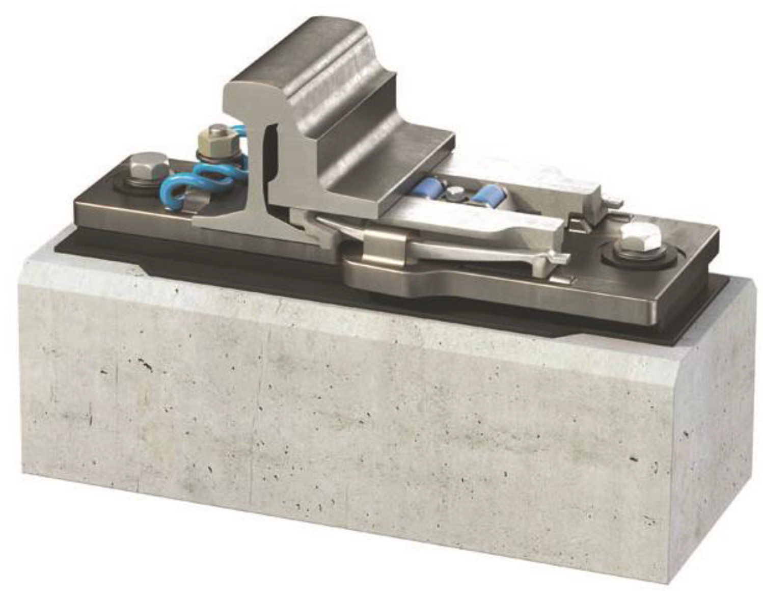
The switch rails are attached to the stock rail by means of welding or bolted joints, depending on the type of turnout, that move in a laterally supported manner on the switch toe, with a part of the switch toe being removed to allow the necessary flexibility to move and couple or uncouple the needle point on the stock rail. In turn, the switch rail head is manufactured to allow proper engagement (Figure 2).
Switch rails have a filed head to enable them to fit together with their respective stock rails, as well as to guide and support the wheels of the train. These switch rails are normally manufactured using normal rails or special switch rails.
Closure rails are the straight or curved rails positioned between the heel of the switch and the toe of the frog. And heel block assemblies are components positioned at the heel of the switch, serving to connect to the adjacent closure rail and functioning as a pivot point for the switch point rail at a fixed distance from the stock rail.
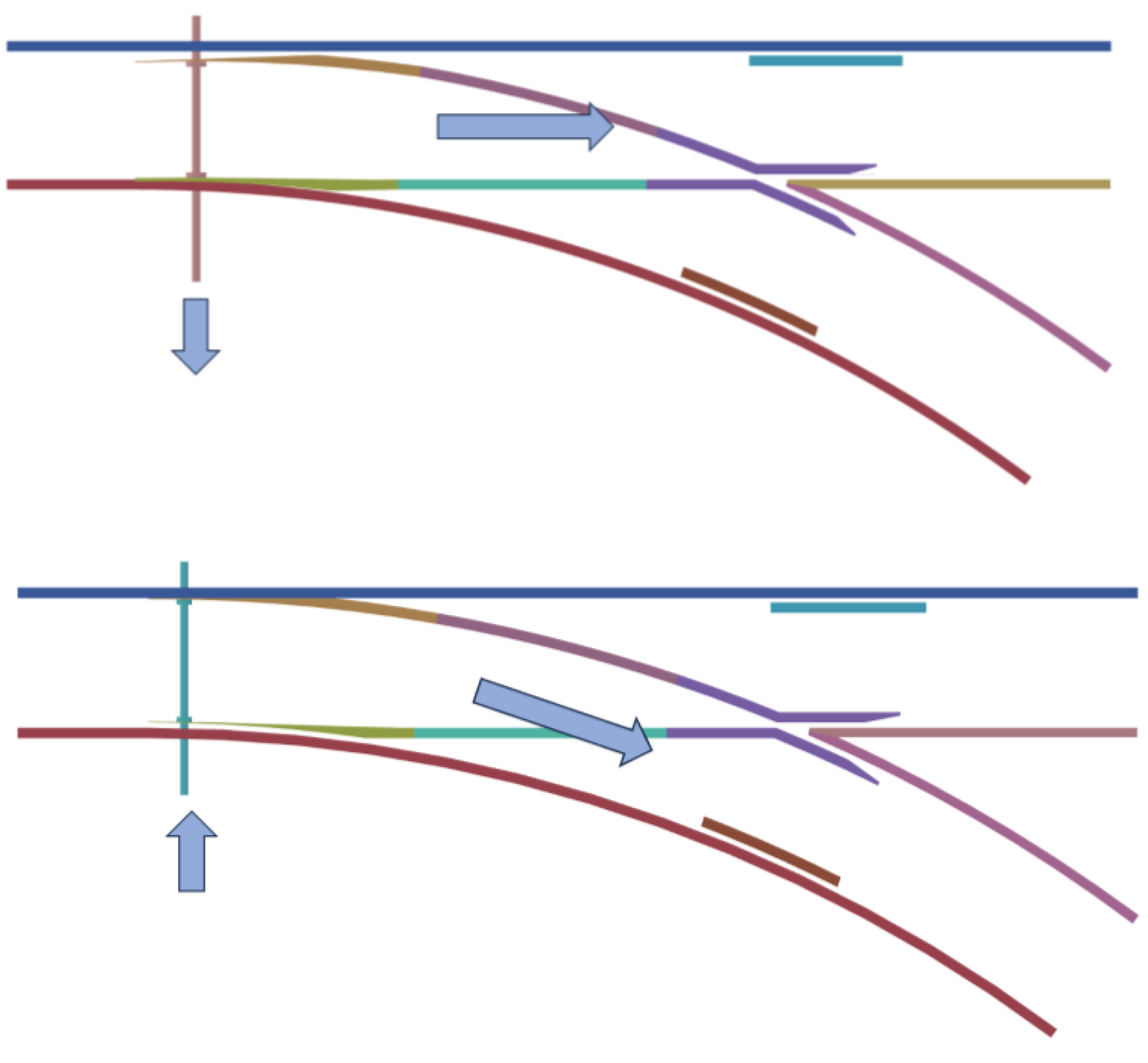
The switch rail is movable at all points, except at the end closest to the crossing, which is called the heel block, while the stock rail is fixed and external to the switch rail. The switch rail is coupled to the stock rail by means of throw bars that allow the deflection of the circulations. Figure 3 shows the way in which a switch rail works.
The crossing is the point at which the change in direction takes effect, and it is a very complex area, especially on complex apparatus or high-speed train traffic. It consists of the frog, guard or check rails, wing rails and crossing gap. The frog is the location at which one of the rails of the direct track crosses the rail on the opposite side of the turnout.
The crossing’s frog can be straight or curved, or even have a turnout in the case of high-speed turnouts, in which case, it is not necessary to use guard rails.
There are two important milestones in the historical development of turnouts. The first milestone occurred in around 1930 when the Deustche Reichsbahn developed a series of turnouts with a completely new and different geometrical form to that of the existing turnouts, trying to adapt its lines to the new possibilities of exploitation that electric and diesel traction presented [3].
From the 1960s onwards, following the success of express trains operating on the Shinkasnen (new Japanese lines), various European railway administrations considered studying a series of high-speed services. France had been maintaining maximum speeds of 200 km/h on some of its most famous express trains (Capitole, Mistral); at the same time, it had carried out many experiments in the field of high-speed trains and has, thus, held the world speed record (330.9 km/h) since 1955, maintaining the privileged position required to make significant progress. Encouraged by Japan’s success, France created a new line in the form of a railway motorway, where the speeds for which their industry had equipped locomotives and towed equipment could be developed [4,5].
Thus, the second milestone came about as a result of the development of high-speed railways in the 1970s in France by the SNCF (Société Nationale des Chemins de Fer Français) with the construction of the TGV Sud Est line. In May 1990, a TGV-Atlantique composition broke the world speed record by reaching a top speed of 515.3 km/h. Another record was a run of 501 km/h through a turnout on a direct track. These new speeds imposed geometrical characteristics on the layouts, which logically included the turnouts, and, in particular, the switches. Problems arose because the turnout of a high-speed train requires very long switch rails and very wide radii.
Therefore, high-speed railways have brought to light the design of much more complex and higher performance turnouts, since, in a conventional turnout, at the crossing of the frog between the two layouts, the train wheel has to pass through a section in which there is no rail, which causes the biggest problems in the turnouts.
Figure 4 shows an actual turnout suitable for use on high-speed railways, on which the complexity of the turnout can be seen.
Switch types can be classified according to the type of rail and the characteristics of their switches and stock rails. Switch rails can either be articulated switch rails or elastic switch rails. Their layout can be secant to the direct track conductor wire on former turnout type A, as well as on type B with a radius of 320 m, or tangent on types C, V and AV, as well as on type B with radius of 500 m.
Among the first changes that were made was the Vignole type, which corresponded to the articulated switch rail typology, in which the articulation is achieved by means of a loose joint, which did not sufficiently tighten the flanges. Its main advantage was the use of complete switch rails without any machining, which makes it very robust. However, it also has major drawbacks. On one hand, the poor behaviour of the switch rail joints (bolts, pins or loose joints) was a frequent cause of breakdowns and accidents. On the other hand, the impossibility of avoiding derailment in the event of a train taking the heel block, for which the switch rails were not properly positioned, was a serious problem [7,8].
In terms of wear, the INSERT type crossing [9] is a successful solution. It is based on rail sections welded to a manganese steel casting insert. The use of a manganese steel insert in this type of crossing makes it possible to take advantage of the special properties of the material and concentrate them in the sensitive area in which the wheel of the rolling stock jumps.
On the other hand, recent technologies have developed new ways to solve these problems, as well as the bumps with the rail, by creating elastic switches (Figure 4) and movable cores and wing rails (Figure 5) that are perfectly joined to the rail, giving more stability to the assembly so that, to avoid the crossing gap, swing nose crossing turnouts can be used, which have movable parts in this area that allow the continuity of the tread to be complete in both paths along the whole turnout (Figure 6).
The swing nose crossing was developed to address the drawbacks of fixed crossings, such as bumpy and jerky wheel over-run and transversely accelerated wheelsets, as well as the resulting high strain on components. The main advantage of the swing nose crossing is the smooth running edge, eliminating the need for check rails.
However, although technological developments have led to the development of technical solutions that allow safe high-speed traffic, these solutions are very complex and costly to maintain.
Despite the critical role that they play in railway operations, turnouts have changed little since their original creation over a century ago. It has become evident that the current designs used in S&C have reached the peak of incremental performance improvement, leaving no room for further enhancement. Therefore, to overcome the constraints that these current designs place on the capacity of the rail network, a radical redesign is required.
Faced with this problem, this work presents a new concept of railway turnout design that aims to solve the drawbacks detected using current technology. To this end, we have opted to use creativity techniques, identifying the main problems to be solved and establishing the design criteria for the new proposed solution. In this way, the aim is to introduce a systematic design methodology that will lead to the proposal of an optimal solution.
Of the existing creativity techniques, TRIZ has been chosen [11]. TRIZ is a knowledge-based creativity technique and very suitable for application to technical problems, as it allows the generation of ideas to be automated.
TRIZ is the Russian acronym for “Theory of Inventive Problem Solving”, i.e., a set of tools focused on automating the creative process, which was developed by Genrich S. Altshuller. Altshuller, during the analysis of thousands of patents, identified solution mechanisms common to different patents. According to TRIZ, there are universal problem-solving mechanisms or principles that automate the creative approach, and these mechanisms have been the basis of innovation. Thus, whatever the problem, it is very likely that someone, somewhere, has already come up with the solution mechanism needed to solve it, even if it has been applied to a different problem. Creative problem-solving involves finding a universal principle or solution mechanism and adapting it to solve a problem [11]. TRIZ has been successfully used in a variety of fields, such as product development [12,13], design engineering [14,15] and process improvement [16] among others. In [17,18], the authors developed a methodology for a simplified version of TRIZ, which is called TRIZ10. The purpose of this methodology is to reduce the learning time and enhance the creative process when tackling technical problems.
Recently, TRIZ has been used in many different applications. In [19], the authors introduced a multianalogy innovation design model that combined the concept of similarity in both design-oriented complex systems and solving invention challenges using TRIZ. To enhance practicality, the model incorporates the use of a digital twin, which incorporates real design information, manufacturing data and maintenance information during the design process.
Additionally, Ref. [20] proposes the concept of functional product hybridisation-integrating TRIZ.
In [21], an enhanced model is proposed, which integrates the Kano model, Quality Function Deployment for Environment, and TRIZ. This enhanced model adopts a component-based approach to systematically design sustainable and innovative products.
Furthermore, in [22], a set of potential improvements is proposed for the traditional liquefied natural gas marine loading arm. These improvement schemes are based on the application of TRIZ.
However, TRIZ has hardly been used as a problem-solving philosophy in the field of research and development of railway systems and components. Analysing the existing references, only one reference has been found concerning the creative design of wheel and axle plugs for railway vehicles using TRIZ/CAE. An analysis of the existing references found only one reference to the creative design of a wheel and axle set for railway vehicles using TRIZ/CAE [23], as well as some references in the field of railway management [24,25]. Therefore, the methodology proposed here is novel and, to the best of authors’ knowledge, has not been applied so far to the design of systems in the railway sector.
Then, the objective of this paper is to propose an innovative solution for the design of a new railway turnout concept. For its design and development, as a contribution of this work, a systematic process of ideation based on TRIZ has been used, and the proposed design addresses the problems associated with crossings by replacing the classic frog with a movable element that sits in the crossing gap and reduces the existing gap, thus minimising the length of the rail gap. Consequently, this method provides greater contact with the rail, minimising wheel impacts on the rail gap and, consequently, decreasing the risk of derailment. It also introduces a new design for the switch rail system, using a piston mechanism with an up and down stroke, which is accompanied by a rotating motor to activate and control the switch movement.
The remaining sections of this article are structured as follows. The first section presents a comprehensive literature review, exploring the current state of the art. The second section outlines the methodology followed in this study. The third section details the various analyses conducted as part of this study. The fourth section presents the results obtained during this study, and it discusses the outcomes of the proposed solutions and their effectiveness. Additionally, it covers the validation process used to verify the design’s functionality and performance. The final section offers the conclusions drawn from the work undertaken in this article. It summarises the key findings, discusses any limitations or future research directions, and provides a closing statement regarding the significance of the study.
By following this structure, the article aims to present a well-organised and coherent exploration of the problem, the proposed solutions, and their validation, concluding with a summary of the overall findings and discussion of the implications of the research.
2. Literature Review
The track switch is a critical component in any railway network as it enables trains to change their route. Its proper functioning is essential to smooth train operations. However, when a track switch fails, significant delays in train services become almost inevitable.
Since the early 1990s, there has been a significant transformation in railway operations, which has been driven in part by new EU directives and increasingly demanding performance targets. These changes have led to a radical shift in how railways are managed and operated. As a consequence, this shift also applies to all railway subsystems. The cost of maintaining railway infrastructure over its lifetime is typically two-to-three times higher than the cost of the original installation. Components, like switches, which involve moving mechanical parts, have particularly high lifetime maintenance costs. Due to their complex natures and constant use, these components require frequent maintenance and repairs, contributing to the overall operating costs of railway networks [26].
There are numerous publications that refer to the design and optimisation of rail turnouts, as they are a critical element involved in the movement of trains.
Related to these materials, in [27], a high-strength steel design is proposed, which is specifically tailored to railway crossing applications. The mechanical properties of this engineered steel exceed those of conventional steels traditionally used in railway turnouts. Moreover, the designed steel exhibits a controlled crack growth under impact fatigue, addressing the primary cause of failure in crossings. This innovative material offers promising benefits in terms of improving the performance and longevity of level crossings.
Regarding the field of crossing geometry design, in [28], a methodology is introduced to enhance the frog’s geometry using a robust optimisation approach. This method incorporates the variability in design parameters within a specified tolerance range into the optimisation problem. To achieve this goal, a multipoint approximation method is employed to solve the optimisation problem.
In [29], a parametric study of wheel transitions at level crossings is carried out, focusing on investigating the effect of various factors, such as local crossing geometry, track alignment, and wheel profiles, on the behaviour of wheel transitions. A multibody system software package is used for this investigation, providing a powerful tool to analyse the complex interactions between wheels and tracks at the crossings.
In [30], a numerical method is presented for the robust optimisation of crossing geometry, considering a representative set of wheel profiles, by parameterising the rail cross-sectional profiles and longitudinal height profiles of both wing rails and the crossing nose.
Similarly, a method to optimise switch rail profile geometry was presented in [31]. Through parameterisation, the method enables efficient optimisation of the switch rail profile geometry, facilitating smoother and more precise rail manufacturing for railway turnouts.
In [32], an optimisation procedure is presented to enhance crossing performance by adjusting the geometry of the crossing, including the wing rail. The primary goal of this optimisation is to reduce the normal contact pressure and wear index while simultaneously shifting the location of the wheel impact, which is also known as the fatigue area, along the crossing. By achieving this shift in the fatigue area, the life of the crossing can be significantly prolonged, resulting in improved durability and reduced maintenance requirements. The optimisation procedure offers a practical and effective means of enhancing the performance and longevity of railway crossings, ultimately contributing to safer and more reliable rail operations.
In [33], the authors focused on investigating the impact on the wheels of a railway vehicle when crossing a deflecting device of a main track turnout, which was specifically located on a straight switch rail. To comprehend this phenomenon, the researchers developed a dynamic model. The paper not only presented the dynamic model, but also provided an explanation of its theoretical foundation.
The objective of [34] was to investigate and determine the influence of switch design on vehicle dynamics by examining the way in which wheel profiles can affect the performance of different systems used in railway operations. By analysing the turnout design’s influence on vehicle dynamics, the researchers sought to gain insights into how design modifications could improve the performance, stability and safety of rail vehicles navigating turnouts. Furthermore, understanding the way in which variability in wheel profiles affects different systems allowed them to assess the adaptability and robustness of these systems under real-world conditions, contributing to the optimisation of rail operations and maintenance strategies.
Ref. [35] presents a method that numerically analyses the dynamic response that occurs when railway vehicles pass. The study involves the use of a Finite Element Method model that includes all components of switches and crossings, including movable parts. A special model of a railway vehicle was specifically developed to calculate the forces at points at which sudden changes in stiffness occur within the railway infrastructure, such as crossings. Additionally, the model accounts for geometrical imperfections in the frog structure, which are crucial to understanding and predicting the dynamic behaviour and forces experienced by the railway vehicle during its passage.
Ref. [36] examines in more detail the vertical dynamics of a railway switch under moving vehicle load. The study involves analysing the effects of this load on the railway turnout’s vertical behaviour. By investigating the vertical dynamics of the railway turnout, the study contributes to a better comprehension of the forces and interactions experienced by vehicles as they traverse these critical components of the railway network. Such insights are valuable in terms of optimising turnout design and maintenance strategies and ensuring safe and reliable rail operations in the Swedish railway system.
In [37], the validity and accuracy of multibody simulation tools were thoroughly analysed to understand their potential in terms of enhancing the design process of railway turnouts. The study focused on assessing the reliability of these tools and the ways in which they can be effectively utilised to improve the design and performance of turnouts. Specifically, the influence of the turnout geometry and track elasticity on vehicle movements was investigated. By studying these parameters, the study aimed to identify ways to optimise turnout design and track properties, ultimately leading to improved vehicle movements and enhanced overall system performance.
Maintenance, which has been the subject of considerable research, is another critical issue for railway turnouts. In [38], the authors present a comprehensive and detailed study covering various aspects of the costs associated with switches and crossings. The aim of this study is to analyse individual maintenance costs, taking into account various factors that contribute to the total maintenance costs of S&C. By analysing individual maintenance costs and different aspects of the overall cost structure, ref. [38] provides valuable information to help railway authorities and maintenance teams to better allocate resources, optimise maintenance practices and make informed decisions regarding S&C management.
In [39], a model is proposed to implement a functional redundancy approach to the functional subsystems of traditional railway switch arrangements, with the aim of enhancing the performance and robustness of railway switch systems, leading to improved reliability and availability.
Another paper [40] describes the estimation of lifetime distributions of individual components within switches and crossings based on field data collected from real-world operations. The study investigated the factors that influence the reliability and lifetimes of S&C components, with a particular focus on maintenance practices. By analysing the lifetime distributions of individual components, the research provides valuable insights into optimising maintenance strategies and improving the overall reliability of S&C units used in railway systems.
A derailment mechanism that focuses on understanding the factors that contribute to derailments in railway systems is presented in a recent study [41]. The researchers evaluated the rationale for the rail clearance maximum and its method of calculation, which is critical to ensuring safe rail operations, and they suggested a new approach to calculating the maximum guardrail clearance based on the running attitude of the vehicle and the angle of attack of the wheelsets. This new approach considers the dynamic behaviour of the vehicle and the angles at which the wheels interact with the guardrails.
In the context of wear, ref. [42] developed a comprehensive methodology for the simulation of wear, rolling contact fatigue and plastic deformation in switches and crossings (S&C) in a mixed traffic situation. This methodology aids researchers in understanding the wear patterns and fatigue behaviours of S&C components, especially when subjected to different types of traffic loads.
Additionally, ref. [43] conducted a parametric study using vehicle–track simulations and multibody simulation software to explore the sensitivity of operational factors and their impact on switch panel wear loading. By varying operational parameters, this study provides insights into the factors influencing wear on switch panels and guides decision-making in terms of optimising switch maintenance and prolonging the life of S&C components.
Lastly, ref. [44] addressed various issues concerning aspects such as maintenance, wear and tear, structural integrity, and the overall performance of the turnout. Addressing these issues is crucial to ensuring the safe and efficient operation of the railway system and enhancing the longevity of S&C units.
In addition, a study of wheel–rail interaction and damage in S&C was carried out in [45]. The focus of the research was to evaluate the influence of stochastic variations in traffic variables on switch and crossing deterioration, helping us to understand the way in which varying traffic conditions affect the wear and degradation of S&C components.
Furthermore, in [46], a study was presented on the improvement of the interaction between vehicles and turnouts. The study focused on optimising the crossing nose shape using a numerical optimisation approach, having the aim of minimising rolling contact fatigue damage and wear in the crossing panel by varying the nose rail shape.
In [47], real-world experiments were conducted to analyse selected ground imperfections in terms of track susceptibility for both linear and non-linear systems. The focus of the research was to evaluate the effect of wheel pressure on the local ground irregularities within the railway switch, showing that these imperfections, along with the calculated additional deflections, can cause disturbances in the progressive movement of the rolling stock.
Finally, ref. [48] presents a process for the production of innovative designs for next-generation switches and crossings to address the capacity constraints imposed on the rail network by current designs, using the Pugh Matrix method to minimise bias and subjectivity in the decision-making process. By incorporating sensitivity analysis, the research investigates potential biases and enhances the reliability of decision-making throughout the design process.
In summary, the findings of this paper contribute to the advancement of the design and optimisation of the railway infrastructure to ensure safer, more efficient and more reliable railway operation in the future.
3. General Principles of the TRIZ Method
TRIZ consists of a methodology and a set of tools that enable a logical and systematic approach to the inventive process. The creator of TRIZ, Genrich Althshuller, after performing an in-depth analysis of patents, realised that the resolution mechanisms of many of them were common, which explains why he stated that 90% of the patents were already resolved.
In the field of inventive problem-solving, the most effective solutions are often found when an inventor tackles a technical problem that involves a contradiction. Such a contradiction arises when an attempt is made to improve one characteristic or parameter of a technical system, which results in the deterioration of another characteristic or parameter within the same system. This conflict presents a challenge in terms of finding an optimal solution that satisfies both competing requirements. When faced with a technical problem, engineers and inventors analyse various characteristics or parameters of the system, such as weight, size, colour, speed, rigidity, etc. These characteristics describe how the technical system works and behaves. By identifying the conflicting characteristics and parameters, which are known as a technical contradiction, engineers can work towards finding a compromise solution that balances the conflicting requirements and yields an innovative resolution to the problem.
There are various tools in the TRIZ methodology, which can be grouped into three main categories: analytical tools, knowledge-based tools and psychological tools. Analytical tools are used for problem formulation, such as functional analysis and the algorithm for inventive problem-solving (ARIZ) [49]. Knowledge-based tools offer recommendations for problem-solving, including the utilisation of the 40 inventive principles [50], the 76 standard solutions and the database of 2500 technical effects. On the other hand, psychological tools are designed to enhance the creative process, such as the “clever little men” method.
One of the tools utilised to resolve technical contradictions is based on the so-called principles. These principles offer generic suggestions for actions to be taken within a technical system, helping engineers to find innovative solutions to complex problems. The 40 principles provide generic suggestions regarding actions to be performed on or within a technical system. Another tool used in TRIZ problem-solving is the Contradiction Matrix. Both the matrix and the 40 principles are in the public domain and available to all engineers to resolve contradictions. The matrix comprises 39 improving and worsening features [51]. In the rows, the first system feature to be improved is selected, while in the columns, the second system feature to be deteriorated accordingly is chosen, as a contradiction exists between the two options. Within the box that corresponds to the selected row and column, there is a recommendation of which inventive principles should be applied to address the contradiction, which is taken from the list of the so-called 40 inventive principles.
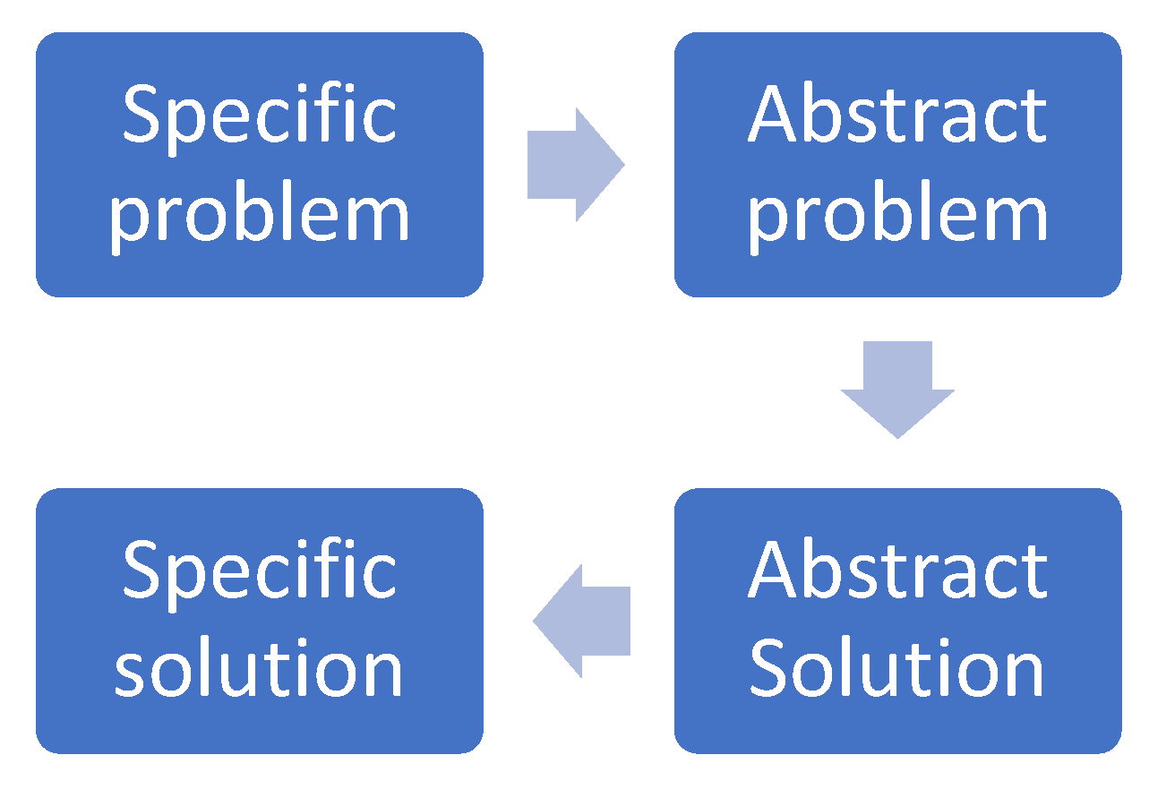
The operation of this tool has been schematised in Figure 7. It starts from a specific problem from which its essential aspects are abstracted, thus turning it into an abstract problem [18,52]. Next, a pre-established abstract solution is selected for this abstract problem. Finally, the selected abstract solution is converted into a specific solution to solve the original specific problem.
Contradictions occur when there are features or effects in the system that appear to be incompatible. A non-inventive way of handling the contradiction would simply be to reach a compromise between the features and effects. TRIZ, on the other hand, attempts to resolve the contradiction by arriving at an inventive solution. The contradictions are of the following two main types:
Technical contradictions: These issues arise when the improvement of one system characteristic leads to the deterioration of a second system characteristic. For example, increasing the power of a vehicle’s engine leads to an increase in the vehicle’s weight.
Physical contradictions: These issues occur when a system feature has both beneficial and detrimental effects. For example, a larger umbrella size allows greater protection from rain, but at the same time, it is more uncomfortable to carry.
Table 1 and Table 2 show the 40 inventive principles and 39 parameters that are used to form the contradiction matrix, according to TRIZ.
Using the 40 principles and combining them with a method of assessing the similarities of a new challenge to previous challenges, problem-solving becomes more systematic. Altshuller developed the Contradiction Matrix [53], i.e., a tool that helps to identify which of the 40 inventive principles are most applicable to solving a particular contradiction. This tool has proven to be very effective and is now included in several TRIZ software packages, including the package that we use, i.e., TRIZ 40 [51]. The use of these tools enables problem solvers to approach complex challenges with a systematic and innovative mindset.
This contradiction matrix is organised in the form of 39 improving parameters and 39 worsening parameters (a 39 × 39 matrix), and each cell entry gives the most commonly used inventive principles that can be used to resolve the contradiction. For a comprehensive version of the matrix, refer to [53,54].
The use of the contradiction matrix follows a four-step process, as indicated in [53]. By following this structured approach, the contradiction matrix offers a systematic way to analyse and resolve complex issues, enabling engineers and researchers to devise innovative solutions and optimise various engineering and operational challenges.
The objective of this paper is to apply the TRIZ methodology, as described above, to design a new and innovative switch and crossing system. Using the tools and principles of TRIZ, our aim is to develop a system that overcomes existing constraints and yields enhanced performance, efficiency and reliability.
4. Results
In the following sections, the design principles of the innovative solution proposed for the crossing and the switch rail will be established through the application of TRIZ and its Contradiction Matrix.
4.1. Design of the Crossing
Following the process described in the previous section, the parameters that represent an improvement in the case of crossing are as follows: No. 9 (Speed), No. 33 (Ease of Operation) and No. 35 (Adaptability). And among the parameters that have a negative effect, we must avoid the following factors: No. 2 (Weight of Stationary Object), No. 10 (Force) and No. 27 (Reliability). This context is shown in Table 3.
Thus, to establish the specific design principles required for the crossing, the generalised 39 × 39 contradiction matrix can be reduced to a simpler 3 × 3 matrix by selecting the three factors with the largest positive effect and the three factors that may have the most negative effects. This matrix is shown in Table 3.
The following passages offer a more detailed description of these contradictions between the negative and positive effects:
The positive effect of a desired increase in train speed (9. Speed) is in contradiction with the property (10. Weight of Stationary Object), since, in principle, a more robust and heavier system is required, which means an increase in the weight of the system. Likewise, the increase in speed is also in contradiction with (10. Force), since, as it moves faster and passes through the gap at a higher speed, a greater impact force is produced. Furthermore, the increased speed puts the reliability of the system at risk (7. Reliability).
On the other hand, the ease of operation of the system (33. Ease of Operation) is in contradiction with the weight (2. Weight), as it will have a positive effect if the weight of the system decreases as it is a negative aspect, as is the impact force (10. Force). It is also in contradiction with an increase in reliability (negative aspect). as systems that are easier to operate can lead to lower reliability (27. Reliability).
Finally, an improvement in (35. Adaptability) requires, in principle, a more complex system design and, therefore, contradicts with weight improvement (2. Weight of Stationary object), strength to resistance (10. Force) and system reliability (27. Reliability).
In Table 3, we can see that the principle of invention corresponding to the technical contradiction matrix is repeated as follows: No. 13 (Do it in Reverse): 4 times. No. 15 (Dynamicity), No. 28 (Replacement of Mechanical System) and No. 35 (Transformation of Properties): 3 times. No. 8 (Anti-Weight), No. 17 (Transition into a New Dimension), No. 27 (Cheap, Short-Lived Objects) and No. 19 (Periodic Action): 2 times.
Table 4 then provides an analysis of the various contradictions and the inventive principles that serve to resolve them. These inventive principles constitute the design principles and design ideas that support the proposed crossing solution. It should be noted that not all of the principles listed in Table 4 are applicable to this particular case. However, it can be seen that the vast majority of them are applicable.
Figure 8 shows a classical crossing configuration through which a wheel passes. A discontinuity of a significant dimension can be observed in the rail, which is called the crossing gap. Several solutions have been developed to minimise this gap. Blue lines represent the frog and green lines represent the wheel and its direction of movement.
One of the most common solutions is the use of pointed frogs, as shown in Figure 9. This solution reduces the gap, but it also presents some disadvantages, as the wheel passing through the crossing causes the transition to bump and eventually leads to wear on the frog’s nose.
On the other hand, the swing-nose crossing might be a good solution, especially for high-speed lines, but it needs more space because it is much longer, it needs many more actuators to move it, and it needs a special manufacturing process, which makes this solution more expensive than the proposed solution. These designs use up to 18 actuators, which are very costly to install and maintain.
Accordingly, and based on the application of the selected inventive principles, the design for the crossing described below is proposed.
The new design introduces a new component called the ‘mobile frog’ to facilitate the passage of the wheel flanges (as shown in Figure 10).
The proposed solution aims to solve the problem of collisions between the wheel flange and the frog’s nose. This problem is caused by the wheel being in the gap of the crossing and not being supported on the rails when the wheel transitions from the direct rail to the crossing.
The objective, therefore, is to reduce the current gap by applying Principle 17 (Transition into a New Dimension) and complementing the system with a mobile part, as indicated by Principle 15 (Dynamicity), which is represented in red in Figure 10. This enhancement not only minimises the existing gap, but also enables higher speeds in the railway operation.
The advantage of using the mobile frog lies in its construction using higher-strength materials, which are divided into several independent assembled pieces. This feature allows easy replacement in the event of wear, without having to remove the entire rail, in accordance with principles 1 (Segmentation), 27 (Cheap, Short-Lived Objects), 13 (Do it in Reverse) and 35 (Transformation of Properties).
The proposed design optimises the use of space by applying Principle 17 (Transition to a New Dimension), which makes it possible to construct a lighter and more robust part by applying Principle 8 (Anti-Weight). However, the most significant aspect to emphasise is its independence from the common crossing, making maintenance much simpler to perform when replacement is necessary due to wear, in accordance with Principle 27 (Cheap, Short-Lived Objects).
In addition, the collision between the wheel and the frog’s nose when a wheel passes through an intersection can result in significant material wear. The proposed solution offers several advantages in this respect. Firstly, the part is easy to replace. This fact makes it easier to work on the active edge to prevent derailment. Secondly, the proposed solution allows the frog to re-align itself, effectively compensating for wear. These benefits contribute to improved maintenance and safety, reducing the potential for wear-related issues and ensuring smoother railway operations.
The shape of this new element, as shown in Figure 10, simplifies the manufacturing process, which helps to reduce the cost of producing it (Principle 27 Cheap. Short-Lived Objects). It is also easy to replace, resulting in low maintenance costs. These cost-efficient features make the proposed solution economically viable and advantageous for use in railway systems.
Compared to the current geometry, the proposed geometry allows a larger bearing surface (Principle 8. Anti-Weight), strengthening the system’s integrity and simplifying maintenance of smaller parts, leading to overall cost savings. The increased bearing surface in the area defined by the wing rails reduces the descent of the wheel during the transition, resulting in the impact of the wheel flange on this surface being reduced as it transitions from the direct rail to the transition. As a result, the risks of derailment are reduced, and higher speeds are possible.
Figure 11 shows a schematic of the proposed design. The different components of the crossing are represented in different colours. In the right side of the figure, the yellow arrow represent the vertical movement of the frog and associated elements.
The component is not rigidly attached to the frog, but it can move upwards and downwards (Principle 15. Dynamic) by means of several lifting cylinders (Principle 28. Replacement of Mechanical System). This design feature allows improved performance, accommodating the wear of the rails resulting from continuous train passage. Four hydraulic cylinders are used for lifting and lowering, allowing fast shifting times (just a few seconds) and better access to the frog area to perform maintenance and repairs. The maximum vertical movement is limited by two lift stop plates, but for additional safety, four position sensors have been incorporated to ensure safe passage, which are located in the guiding tubes. This upward movement also solves the problem of alignment with the rails, effectively compensating for irregularities caused by wear affecting the frog.
The system allows us to automatically reverse the situation, ensuring the safety of the operation (Principle 13. Do it in Reverse).
The location of the support structure of the mobile frog is below the level of the running surface to allow adequate upward and rotational movement of the motorised assembly, without any type of interference from the passage of the train, since in the passage of a wheel through the crossing gap, it is essential to ensure that the surface area of interaction between the wheel and the wing rail is as large as possible in order to defer the effects of wear. On the other hand, the angle of attack of the wheel on the opposite wing rail should be as small as possible, meaning that the kinetic energy lost in the collision will be minimal. These conditions must be met simultaneously with the tolerances on the usual geometric dimensions of the crossing, which are variable within a certain order due to the effects of wear and chattering.
4.2. Design of the Switch Rail
For the switch rail innovation, the following parameters are selected (Table 5):
Table 5 shows that the principle of invention corresponding to the technical contradiction matrix is repeated as follows: No. 28 (Replacement of Mechanical System) and No. 15 (Dynamicity): 4 times. No. 35 (Transformation of Properties), No. 8 (Anti-Weight), No. 19 (Periodic Action), and No. 10 (Preliminary Action): 3 times. No. 13 (Do it in Reverse), and No. 27 (Cheap, Short-Lived Objects): 2 times.
The following results show a more detailed description of these contradictions, as seen in Table 6:
The proposed solution is described below. As described above, the current turnouts present a significant problem. On one hand, they have high mechanical complexity. On the other hand, they have high costs, including the maintenance necessary to maintain the required safety, since it is at this point of the crossing that the greatest number of accidents occur. The proposed new design seeks to simplify, economise and increase the safety of the system. Figure 12 schematically shows the design’s development. The different components of the switch are represented in different colours.
It should be noted that the proposed solution is based on the switch drive mechanism. It is clear that the system must have a needle locking mechanism, although these mechanisms are not shown in the diagram presented.
The system is based on the concept of the elastic switch rail (13 Do it in Reverse), which is coupled to either track without discontinuity and forged and stamped (35 Transformation of Properties) in the heel block to allow it to be welded to the rails that follow it inside of the turnout. The switch rail shall be subject to an up and down movement (19 Periodic Action), as well as a left and right turning movements (19 Periodic Action). Combining both movements, it shall be interlocked between the rail and the guard rail in order to prevent movement during the passage of the train.
The aim of the up–down movement is to raise the switch rails (15 Dynamicity) when the switch rail is moving sideways. The aim of this technique is to lighten the structure and prevent friction between the switch toe of the switch rail and the stock rails when the connecting plate on which the switch rails rest is raised.
Figure 13 shows the sequence of operations. When the switch rails are raised (1), they are cantilevered. At this point, a motor actuator (28 Replacement of Mechanical System) rotates an eccentric pin, which converts the rotation of the motor into a lateral displacement of the connecting plate, producing the displacement of the switch rail (2).
The lifting mechanism consists of the cylinders (28 Replacement of Mechanical System) responsible for lifting the connecting plate on which the switch rails rest (their vertical movement is represented with blue arrows and number 1). In this position, the motor actuator makes the corresponding turnout to move the switch rails towards the rail, which is the object of the turnout. Thus, the rotation of the motor actuator is converted into the lateral displacement of the switch rail (15 Dynamicity) (represented with red arrows and number 2). Once this step has been taken, it will again produce the downward movement to the rest position (represented with yellow arrows and number 3).
Figure 14 shows how the rotation of the motor is transformed, which moves the crank that is attached to it, and this, at the same time, produces the displacement of the connection plate by sliding the pin at the end of the crank along the slide of the connection plate. The arrows in purple indicate the movements that are transformed.
This results in a simple, lighter (8 Anti-Weight), low-cost (27 Cheap Short-Living Objects) and highly reliable system signed by assembled elements that are easy to replace in case of failure or breakdown (1 Segmentation).
5. Discussion and Validation
The designs have been numerically validated by simulating the dynamic behaviour of a passing train using Universal Mechanism 7.0 software [55].
The geometry and the operating conditions of the proposed design have been validated for a conventional line turnout, which is valid at speeds of up to 200 km/h. The design may also be valid for high-speed lines, but this status would require that different dimensions be adapted to suit these conditions. This aspect will be the subject of future research.
The analyses were carried out to measure two different speeds for the front bogie of a freight wagon.: 40 km/h and 60 km/h. Lateral frictional resistance was analysed to understand the operation of the turnout. These results were obtained for all four wheels of the bogie.
Figure 15 and Figure 16 show the total friction on the two front wheels of the bogie with a conventional turnout and with the proposed turnout, respectively.
Upon analysing these figures, it is clear that the new design outperforms the classic design, demonstrating superior performance and efficiency.
Figure 17 and Figure 18 show the total lateral and vertical forces suffered by the wheels upon contact with the crossing.
Table 7 and Table 8 summarise these results and show the differences between a conventional crossing and the proposed crossing.
Finally, Nadal’s criterion is used to relate the vertical and lateral forces—which were analysed previously—in order to determine the real possibility of a rise in any of the wheels of our bogie. Therefore, despite being a consequence of the calculations shown above, it is possible to analyse whether the probability of uplift has been reduced in the heart area in a simple manner, which is the primary objective of this project. If the vertical force is greater than the lateral force in the wheel–rail contact, Nadal’s criterion will be less than one, and, therefore, it is a safe zone. Nadal’s criterion is one of the most conservative measures in the field of railway derailments.
As shown in Figure 19, until the bogie begins to take the curve (with a radius of 300 m), Nadal’s criterion is centred around 0 because of the low risk of derailment on the straight. After 0.5 s, the bogie is inscribed in the circumference of the turn itself, such that its lateral force and flange–rail contact increase, with Nadal’s criterion increasing to almost 0.8. This figure is the highest value and, therefore, indicates at which point there is more theoretical risk of derailment. Due to the construction characteristics of the crossing, although Nadal’s criterion is high, if the speed is adequate in this section, derailment should not occur. During the turn, the values of the criterion stabilise at around 0.4—a reasonable value representing a low risk of derailment. Before facing the gap space, as a consequence of the straightening of the road, the lateral effort is again reduced, and the value of Nadal’s criterion decreases. At around 2.5 s, once the left front wheel has passed the gap and has lowered the height of its centre of mass because of the lack of support, a shock occurs that increases the risk of derailment in the surroundings to 0.6 in terms of Nadal’s criterion.
As explained, Nadal’s criterion presented a reduction as being a consequence of the elongation of the point of the heart, and the most interesting values were observed in the right front wheel, which passes between the right rail and the check rail. For both wheels, the risk of derailment was reduced relative to the classic crossing, as reflected by a 6% reduction in Nadal’s criterion.
A more detailed analysis of results can be seen in the previous work referenced in [55].
6. Conclusions
This work has proposed an innovative solution for the design of a new railway turnout concept. For its design and development, as a contribution of this work, a systematic process of ideation based on TRIZ has been used, i.e., the tool of the matrix of contradictions. TRIZ is a methodology or set of tools that allows the creative process to be automated. Unlike other creative approaches, TRIZ is based on knowledge, which explains why it is highly recommended for resolving technical problems. TRIZ has great power when it comes to creating new designs and innovations, as has already been demonstrated in different sectors; however, it has not been used until now in the railway sector beyond issues related to railway management and operation.
With regard to the use of TRIZ, based on the contradiction matrix, the inventive principles of application in the design of the turnout have been chosen. The most applicable ones were Segmentation, Do it in Reverse, Dynamicity, Transition into a New Dimension, Periodic Action, Cheap, Short-Lived Objects, Replacement of Mechanical System, Transformation of Properties and Anti-Weight, corresponding to principles applicable to a simpler, lighter, more efficient and more reliable design, with certain moving parts driven by easily automated controlled elements.
Based on the systematic use of the TRIZ principles, the proposed design addresses the problems associated with switches and crossings by replacing the classic frog with a movable element that sits in the crossing gap and reduces the existing gap, thus minimising the length of the rail gap and, consequently, providing greater contact with the rail, minimising wheel impacts on the rail gap and, consequently, decreasing the risk of derailment. It also introduces a new design for the switch rail system, using a piston mechanism with an up and down stroke, that is accompanied by a rotating motor at the top for controlled movement.
Based on the current state of the art, we can infer from the references that there is no similar innovation, as current systems are much more complex and costly than the one proposed in this study.
Future research opens the possibility of the application of this design to high-speed lines, as well as electronic control systems, for the start and end movement at the appropriate point on the rail that needs to be set at the passage of the train, as well as its integration into the complex signalling systems that can control it.
Author Contributions
Conceptualisation, A.J.S., J.F. and J.D.C.-M.; methodology, A.J.S., J.F. and J.D.C.-M.; validation, A.J.S. and J.F.; formal analysis, A.J.S., J.F. and J.D.C.-M.; investigation, A.J.S., J.F. and J.D.C.-M.; writing—original draft preparation, A.J.S. and J.F.; writing—review and editing, A.J.S. and J.F.; supervision, J.F. All authors have read and agreed to the published version of the manuscript.
Funding
This research received no external funding.
Institutional Review Board Statement
Not applicable.
Informed Consent Statement
Not applicable.
Data Availability Statement
Not applicable.
Conflicts of Interest
The authors declare no conflict of interest.
References
- Railsystem.net. Railway Turnout. Available online: https://railsystem.net/turnouts/ (accessed on 11 April 2023).
- Voestalpine. Switch Section. Available online: https://www.voestalpine.com/railway-systems/en/products/elastic-switch-roller-system-varoll/ (accessed on 26 June 2023).
- Wang, P. Design of High-Speed Railway Turnouts; Elsevier: Amsterdam, The Netherlands, 2015. [Google Scholar] [CrossRef]
- Eurostat Statistics. Eurobase Reference. Available online: https://ec.europa.eu/eurostat/web/transport/data/database (accessed on 29 March 2023).
- Andersson, C.; Dahlberg, T. Wheel/rail impacts at a railway turnout crossing. Proc. Inst. Mech. Eng. Part F J. Rail Rapid Transit 1998, 212, 123–134. [Google Scholar] [CrossRef]
- Voestalpine. System Solutions for High Speed Traffic. Available online: https://www.voestalpine.com/railway-systems/en/applications/high-speed-traffic/ (accessed on 11 April 2023).
- MITMA. Observatorio del Ferrocarril en España. Available online: https://www.mitma.gob.es/ferrocarriles/observatorios/observatorio-del-ferrocarril-en-espana (accessed on 29 March 2023).
- EU Directive 440/91. Development of the EC’s Railways. Available online: https://eur-lex.europa.eu/legal-content/EN/TXT/HTML/?uri=CELEX:31991L0440&from=EN (accessed on 29 March 2023).
- KZN Academy. INSERT Type Crossing. Available online: http://kzn.pl/akademia-krzyzownice-z-wkladka-typu-insert/ (accessed on 15 August 2023).
- Voestalpine. Swing Nose Crossing. Available online: https://www.voestalpine.com/railway-systems/en/products/swing-nose-crossing-00001/ (accessed on 17 August 2023).
- Ekmekci, I.; Nebati, E.E. Triz Methodology and Applications. Procedia Comput. Sci. 2019, 158, 303–315. [Google Scholar] [CrossRef]
- Wu, Y.; Zhou, F.; Kong, J. Innovative design approach for product design based on TRIZ, AD, fuzzy and Grey relational analysis. Comput. Ind. Eng. 2020, 140, 106276. [Google Scholar] [CrossRef]
- Weijie, J. Research and Application of Mechanical Product Design Process Based on QFD and TRIZ Integration. J. Phys. Conf. Ser. 2020, 1544, 012088. [Google Scholar] [CrossRef]
- Ang, M.C.; Ng, K.W.; Ahmad, S.A.; Wahab, A.N.A. An Engineering Design Support Tool Based on TRIZ. In Advances in Visual Informatics, Proceedings of the Third International Visual Informatics Conference, IVIC 2013, Selangor, Malaysia, 13–15 November 2013; Springer International Publishing: New York, NY, USA; pp. 115–127. [CrossRef]
- Dumas, D.; Schmidt, L.C.; Alexander, P.A. Predicting creative problem solving in engineering design. Think. Ski. Creat. 2016, 21, 50–66. [Google Scholar] [CrossRef]
- Sojka, V.; Lepšík, P. Use of TRIZ, and TRIZ with Other Tools for Process Improvement: A Literature Review. Emerg. Sci. J. 2020, 4, 319–335. [Google Scholar] [CrossRef]
- Cano-Moreno, J.D.; Reina, J.M.A.; Martínez, F.V.S.; Becerra, J.M.C. Using TRIZ10 for enhancing creativity in engineering design education. Int. J. Technol. Des. Educ. 2021, 32, 2749–2774. [Google Scholar] [CrossRef]
- Moreno, J.D.C.; Becerra, J.M.C. TRIZ10. The decalogue of technical creativity. DYNA 2018, 93, 586. [Google Scholar] [CrossRef]
- Nie, Z.; Cao, G.; Zhang, P.; Peng, Q.; Zhang, Z. Multi-Analogy Innovation Design Based on Digital Twin. Machines 2022, 10, 652. [Google Scholar] [CrossRef]
- Liu, F.; Jing, Y.; Shao, P.; Zhang, Y. Research on Design Method of Product Functional Hybridization for Integrated Innovation. Appl. Sci. 2022, 12, 10302. [Google Scholar] [CrossRef]
- Choi, J.-Y.; Kim, S.-H.; Han, K.-S.; Chung, J.-S. Application of Failure Mode Effects Analysis for Maintenance of Turnout System on Serviced Urban Rapid Transit. Appl. Sci. 2023, 13, 2978. [Google Scholar] [CrossRef]
- Mei, J.; Feng, W.; Liang, Z. Improved Design of LNG Marine Loading Arm Docking Method Based on TRIZ Theory. Appl. Sci. 2023, 13, 4525. [Google Scholar] [CrossRef]
- Huh, Y.-J.; Kim, J.-M.; Hong, S.-D. Creative Design of Cap for Wheel and Axle of Railway Vehicle by Using TRIZ/CAE. J. Korea Acad. Coop. Soc. 2013, 14, 2581–2587. [Google Scholar] [CrossRef]
- Bersano, G.; Fayemi, P.-E. Application of TRIZ and Innovation Management Theory on Decision Support for Transport Infrastructure. In New Opportunities for Innovation Breakthroughs for Developing Countries and Emerging Economies, Proceedings of the 19th International TRIZ Future Conference, TFC 2019, Marrakesh, Morocco, 9–11 October 2019; Springer International Publishing: New York, NY, USA; pp. 486–493. [CrossRef]
- Kosarev, A.B.; Rimskaya, O.N.; Anokhov, I.V. Advancing the development of railway transport with the help of digital technologies. Mod. Transp. Tion Syst. Technol. 2021, 7, 90–105. [Google Scholar] [CrossRef]
- Marquez, F.P.G.; Weston, P.; Roberts, C. Failure analysis and diagnostics for railway trackside equipment. Eng. Fail. Anal. 2007, 14, 1411–1426. [Google Scholar] [CrossRef]
- Kumar, A.; Makineni, S.; Dutta, A.; Goulas, C.; Steenbergen, M.; Petrov, R.; Sietsma, J. Design of high-strength and damage-resistant carbide-free fine bainitic steels for railway crossing applications. Mater. Sci. Eng. A 2019, 759, 210–223. [Google Scholar] [CrossRef]
- Wan, C.; Markine, V.; Dollevoet, R. Robust optimisation of railway crossing geometry. Veh. Syst. Dyn. 2016, 54, 617–637. [Google Scholar] [CrossRef]
- Wan, C.; Markine, V.L. Parametric study of wheel transitions at railway crossings. Veh. Syst. Dyn. 2015, 53, 1876–1901. [Google Scholar] [CrossRef]
- Pålsson, B.A. Optimisation of railway crossing geometry considering a representative set of wheel profiles. Veh. Syst. Dyn. 2015, 53, 274–301. [Google Scholar] [CrossRef]
- Pålsson, B.A. Design optimisation of switch rails in railway turnouts. Veh. Syst. Dyn. 2013, 51, 1619–1639. [Google Scholar] [CrossRef]
- Markine, V.; Wan, C. Performance Optimised Geometry of Railway Crossings: Design and Implementation. Int. J. Railw. Technol. 2016, 5, 1–25. [Google Scholar] [CrossRef]
- Bugarín, M.R.; Díaz-De-Villegas, J.-M.G. Improvements in railway switches. Proc. Inst. Mech. Eng. Part F J. Rail Rapid Transit 2002, 216, 275–286. [Google Scholar] [CrossRef]
- Lagos, R.F.; Alonso, A.; Vinolas, J.; Pérez, X. Rail vehicle passing through a turnout: Analysis of different turnout designs and wheel profiles. Proc. Inst. Mech. Eng. Part F J. Rail Rapid Transit 2012, 226, 587–602. [Google Scholar] [CrossRef]
- Salajka, V.; Smolka, M.; Kala, J.; Plášek, O. Dynamical response of railway switches and crossings. MATEC Web Conf. 2017, 107, 00018. [Google Scholar] [CrossRef]
- Johansson, A.; Pålsson, B.; Ekh, M.; Nielsen, J.C.; Ander, M.K.; Brouzoulis, J.; Kassa, E. Simulation of wheel–rail contact and damage in switches & crossings. Wear 2011, 271, 472–481. [Google Scholar] [CrossRef]
- Lagos, R.; Emeterio, A.S.; Vinolas, J.; Alonso, A.; Aizpun, M. The Influence of Track Elasticity when travelling on a Railway Turnout. In Proceedings of the Second International Conference on Railway Technology: Research, Development and Maintenance, Corsica, Ajaccio, Spain, 8–11 April 2014. [Google Scholar] [CrossRef]
- Nissen, A. Classification and cost analysis of switches and crossings for the Swedish railway: A case study. J. Qual. Maint. Eng. 2009, 15, 202–220. [Google Scholar] [CrossRef]
- Bemment, S.D.; Goodall, R.M.; Dixon, R.; Ward, C.P. Improving the reliability and availability of railway track switching by analysing historical failure data and introducing functionally redundant subsystems. Proc. Inst. Mech. Eng. Part F J. Rail Rapid Transit 2018, 232, 1407–1424. [Google Scholar] [CrossRef]
- Rama, D.; Andrews, J.D. A reliability analysis of railway switches. Proc. Inst. Mech. Eng. Part F J. Rail Rapid Transit 2013, 227, 344–363. [Google Scholar] [CrossRef]
- Wang, P.; Wang, S.; Zhao, Z. Mechanism of Derailment at the Guardrail Position of Turnout and a Reasonable Guardrail Interval Limit. Appl. Sci. 2022, 12, 8496. [Google Scholar] [CrossRef]
- Nicklisch, D.; Kassa, E.; Nielsen, J.; Ekh, M.; Iwnicki, S. Geometry and stiffness optimization for switches and crossings, and simulation of material degradation. Proc. Inst. Mech. Eng. Part F J. Rail Rapid Transit 2010, 224, 279–292. [Google Scholar] [CrossRef]
- Hiensch, E.J.M.; Burgelman, N. Switch Panel wear loading—A parametric study regarding governing train operational factors. Veh. Syst. Dyn. 2017, 55, 1384–1404. [Google Scholar] [CrossRef]
- Kisilowski, J.; Kowalik, R. Railroad Turnout Wear Diagnostics. Sensors 2021, 21, 6697. [Google Scholar] [CrossRef]
- Pålsson, B.A.; Nielsen, J.C. Wheel–rail interaction and damage in switches and crossings. Veh. Syst. Dyn. 2012, 50, 43–58. [Google Scholar] [CrossRef]
- Wan, C.; Markine, V.; Shevtsov, I. Improvement of vehicle–turnout interaction by optimising the shape of crossing nose. Veh. Syst. Dyn. 2014, 52, 1517–1540. [Google Scholar] [CrossRef]
- Kisilowski, J.; Kowalik, R. Method for Determining the Susceptibility of the Track. Appl. Sci. 2022, 12, 12534. [Google Scholar] [CrossRef]
- Boghani, H.C.; Ambur, R.; Blumenfeld, M.; Saade, L.; Goodall, R.M.; Ward, C.P.; Plášek, O.; Gofton, N.; Morata, M.; Roberts, C.; et al. Sensitivity enriched multi-criterion decision making process for novel railway switches and crossings—A case study. Eur. Transp. Res. Rev. 2021, 13, 6. [Google Scholar] [CrossRef]
- Stage Gate Inc. ARIZ (TRIZ). Available online: https://www.stage-gate.la/glosario/ariz-triz/ (accessed on 1 June 2023).
- Technical Innovation Center Inc. 40 Principles. Available online: https://triz.org/principles/ (accessed on 1 June 2023).
- SolidCreativity. TRIZ40. Available online: https://www.triz40.com/TRIZ_GB.php (accessed on 11 April 2023).
- Moreno, J.D.C.; Becerra, J.M.C. TRIZ: Enfoque probabilístico para la resolución de problemas técnicos. DYNA Manag. 2018, 6, 9. [Google Scholar] [CrossRef]
- Childs, P.R. Ideation. In Mechanical Design Engineering Handbook; Elsevier: Amsterdam, The Netherlands, 2019; pp. 75–144. [Google Scholar] [CrossRef]
- TRIZ40. 40 TRIZ Principles. Available online: https://www.triz40.com/aff_Principles_TRIZ.php (accessed on 1 June 2023).
- Sala, A.J.; Felez, J.; Sanz, J.d.D.; Gonzalez, J. New Anti-Derailment System in Railway Crossings. Machines 2022, 10, 1224. [Google Scholar] [CrossRef]
Figure 1.
Components of a railway turnout.

Figure 2.
Cross section of the switch, reprinted with permission from Ref. [2], voestalpine Railway Systems.
Figure 2.
Cross section of the switch, reprinted with permission from Ref. [2], voestalpine Railway Systems.

Figure 3.
Schematic diagram of a turnout.

Figure 4.
High-speed turnout, reprinted with permission from Ref. [6], voestalpine Railway Systems.
Figure 4.
High-speed turnout, reprinted with permission from Ref. [6], voestalpine Railway Systems.

Figure 5.
Flexible switch.

Figure 6.
Swing nose crossing, reprinted with permission from Ref. [10], voestalpine Railway Systems.
Figure 6.
Swing nose crossing, reprinted with permission from Ref. [10], voestalpine Railway Systems.

Figure 7.
TRIZ methodological approach.

Figure 8.
Usual configuration of a crossing.

Figure 9.
Pointed frog.

Figure 10.
Crossing with proposed mobile frog.

Figure 11.
Scheme and components of the new design.

Figure 12.
Schematic of the developed design.

Figure 13.
Sequence of movements performed.

Figure 14.
Detail of the mechanism used to transform the motor rotation into the displacement of the connecting plate.
Figure 14.
Detail of the mechanism used to transform the motor rotation into the displacement of the connecting plate.

Figure 15.
Total frictional resistance of the front wheels in a standard turnout.

Figure 16.
Total frictional resistance of the front wheels in the proposed turnout.

Figure 17.
Total lateral force in the proposed turnout.

Figure 18.
Total vertical force in the proposed turnout.

Figure 19.
Nadal’s criterion application.


Table 1.
Summary of the 40 Principles [50].
Table 1.
Summary of the 40 Principles [50].
| 1. Segmentation | 11. Beforehand Cushioning | 21. Skipping | 31. Porous Material |
| 2. Tanking Out | 12. Equipotentiality | 22. Convert Harm into Benefit | 32. Changing the Colour |
| 3. Local Quality | 13. Do it in Reverse | 23. Feedback | 33. Homogeneity |
| 4. Asymmetry | 14. Spheroidality–Curvature | 24. Intermediary | 34. Discarding and Recovering |
| 5. Merging | 15. Dynamicity | 25. Self-Service | 35. Transformation of Properties |
| 6. Universality | 16. Partial or Excessive Actions | 26. Copying | 36. Phase Transition |
| 7. Nested Doll | 17. Transition into a New Dimension | 27. Cheap, Short-Lived Objects | 37. Thermal Expansion |
| 8. Anti-Weight | 18. Mechanical Vibration | 28. Replacement of Mechanical System | 38. Accelerated Oxidation |
| 9. Prior Anti-Action | 19. Periodic Action | 29. Pneumatics and Hydraulics | 39. Inert Environment |
| 10. Preliminary Action | 20. Continuity of Useful Action | 30. Flexible Shells or Thin Films | 40. Composite Materials |
Table 2.
Summary of the 39 parameters [51].
Table 2.
Summary of the 39 parameters [51].
| 1. Weight of Moving Object | 11. Stress or Pressure | 21. Power | 31. Object-Generated Harmful Factors |
| 2. Weight of Stationary Object | 12. Shape | 22. Loss of Energy | 32. Ease of Manufacture |
| 3. Length of Moving Object | 13. Stability of the Object’s Composition | 23. Loss of Substance | 33. Ease of Operation |
| 4. Length of Stationary Object | 14. Strength | 24. Loss of Information | 34. Ease of Repair |
| 5. Area of Moving Object | 15. Duration of Action by a Moving Object | 25. Loss of Time | 35. Adaptability or Versatility |
| 6. Area of Stationary Object | 16. Duration of Action by a Stationary Object | 26. Quantity of Substance/the Matter | 36. Device Complexity |
| 7. Volume of Moving Object | 17. Temperature | 27. Reliability | 37. Difficulty of Detecting and Measuring |
| 8. Volume of Stationary Object | 18. Illumination Intensity | 28. Measurement Accuracy | 38. Extent of Automation |
| 9. Speed | 19. Use of Energy by Moving Object | 29. Manufacturing Precision | 39. Productivity |
| 10. Force | 20. Use of Energy by Stationary Object | 30. External Harm Affects the Object |
Table 3.
Matrix of technical contradictions for the crossing innovation.
| Negative Effect | ||||
| 2. Weight of Stationary Object | 10. Force | 27. Reliability (Reliability) | ||
| Positive Improvement | 9. Speed (train) | 13, 28, 15, 19 | 11, 35, 27, 28 | |
| 33. Ease of Operation | 6, 13, 1, 32 | 28, 13, 35 | 17, 27, 8, 40 | |
| 35. Adaptability | 19, 15, 29 | 15, 17, 18, 20 | 35, 13, 8, 24 | |
Table 4.
Contradictions and principles applied to the crossing.
| Contradiction | Associated Inventive Principles and Proposed Design Concepts |
|---|---|
| 9. Speed—10. Force | 15. Dynamicity: The principle suggests turning an immobile object into a mobile object. The frog, which is traditionally a static element in the crossing, becomes a mobile and vertically movable element. 28. Replacement of Mechanical System: the required drive for the swing nose crossing recommends the use of simpler and more powerful hydraulic elements, instead of more complex and less reliable mechanical elements. |
| 9. Speed—27. Reliability | 27. Cheap, Short-Lived Objects: the principle suggests using simpler, less costly and less maintenance-intensive systems. 28. Replacement of Mechanical System: as shown in the previous contradiction, the resolution of this contradiction recommends replacing mechanical elements with hydraulic drives. 35. Transformation of Properties: To solve this contradiction, it is proposed to use particularly resistant materials in the critical wear zone, such as the discontinuity in the crossing where the frog is introduced. It is practical to incorporate a moving frog made of a higher resistance material that can be easily substituted when it wears out, without having to replace the rail. |
| 33. Ease of Operation—2. Weight of Stationary Object. | 1. Segmentation: the solution to the contradiction recommends dividing the crossing into independent and replaceable elements that are easier to assemble and disassemble. |
| 33. Ease of Operation/Manufacturing—10. Force | 13. Do it in Reverse. as stated in the previous case, the conversion of traditionally fixed parts (frog) to mobile parts (mobile frog) provides greater ease of operation and reduces the impact force when the wheel crosses the crossover gap. 35. Transformation of Properties: The intention is to use the same type of steel used in the construction of all railway systems, albeit reinforced in the switch gear most exposed to shocks or knocks, such as the frog. Specifically, the alloy described as “Mangalloy” will be used, which will increase the element’s service life. |
| 33. Ease of Operation—27. Reliability | 8. Anti-Weight: The weight of the traditional and fully mechanical crossing is compensated by hydraulic cylinders that provide the lifting force. 27. Cheap, Short-Lived Objects: the solution is again associated with the use of simpler, less costly and less maintenance-intensive elements. |
| 35. Adaptability or Versatility—2. Weight of Stationary Object | 15. Dynamicity: again, the application of this principle to resolve this contradiction recommends the consideration of a mobile element (mobile frog), which is lighter than the solutions that have been used so far. |
| 35. Adaptability or Versatility—10. Force | 15. Dynamicity: the adaptability of the new mobile system allows us to reduce the impact force when the train wheel crosses the rail discontinuity. 17. Transition into a New Dimension: the principle suggests adapting dimensions of existing systems to ensure that the new design matches the existing track geometry of the current railway system in order to reduce the gap in the discontinuities appearing at the crossing and, thus, reduce the risk of derailment. |
| 35. Adaptability or Versatility—27. Reliability | 8. Anti-Weight: This principle recommends proposing a geometry that offers a larger bearing surface than the current example, reinforcing the system’s stability and simplifying maintenance with a lighter and more straightforward element. 35. Transformation of Properties: The economic cost remains the same for the type of steel, although the cost of the installation decreases as fewer elements are used, which are more adaptable and replaceable in case of wear and tear, are simpler and have lower maintenance costs. |
Table 5.
Technical contradiction matrix used for the switch rail innovation.
| Negative Effect | ||||
| 10. Current Intensity (electrical) | 27. Reliability | 35. Adaptability | ||
| Positive Improvement | 2. Weight of Stationary Object | 8, 10, 19, 35 | 10, 28, 8, 3 | 19, 15, 29 |
| 9. Speed (Piston and Actuator) | 13, 28, 15, 19 | 11, 35, 27, 28 | 15, 10, 26 | |
| 33. Ease of Operation | 28, 13, 35 | 17, 27, 8, 40 | 15, 34, 1, 16 | |
Table 6.
Contradictions and principles applied to the switch rail.
| Contradiction | Associated Inventive Principles and Proposed Design Concepts |
|---|---|
| 2. Weight of Stationary Object—10. Current Intensity (Electrical) | 8. Anti-Weight: The contradiction recommends using lighter and lighter-weight systems than traditional ones. 19. Periodic Action: the contradiction recommends the application of an oscillating motion to drive the switch rail produced by an electric motor actuator. 35. Transformation of Properties: to resolve this contradiction, it is proposed to use especially resistant materials in the switch rail to give it the necessary elasticity to produce the required movement. |
| 2. Weight of Stationary Object—27. Reliability | 8. Anti-Weight: the contradiction recommends using lighter and lighter-weight systems than traditional systems, resulting in higher reliability. 28. Replacement of Mechanical System: the required drive recommends the use of simpler electrical and hydraulic elements, instead of more complex and less reliable mechanical elements. |
| 2. Weight of Stationary Object—35. Adaptability | 15. Dynamicity: the new design is lighter and provides greater adaptability as components can be easily replaced. 19. Periodic Action: the contradiction again recommends the use of an oscillating movement to drive the switch rail produced by an electric motor actuator, which is lighter and more adaptable than a mechanical system. |
| 9. Speed (Piston and Actuator)—10. Current Intensity (Electrical) | 13. Do it in Reverse: contradiction recommends the use of flexible switch rails, which are easier to operate and allow the switch rail to return to its natural position in the event of a power failure. 15. Dynamicity: the new electro-hydraulic actuation system achieves faster actuation. 19. Periodic Action: the contradiction again recommends the application of an oscillating movement for the switch rail drive produced using an electric motor actuator, faster than a mechanical system. 28. Replacement of Mechanical System: the required drive recommends the use of faster electric and hydraulic elements, rather than more complex and slower moving mechanical elements. |
| 9. Speed (Piston and Actuator)—27. Reliability | 27. Cheap, Short-Lived Objects: the principle recommends using simpler, less costly and less maintenance-intensive systems. 28. Replacement of Mechanical System: the required drive recommends the use of electrical and hydraulic elements, rather than more complex and less reliable mechanical elements. 35. Transformation of Properties: replacing mechanical systems with electric and hydraulic systems provides faster operation and greater reliability. |
| 9. Speed (Piston and Actuator)—35. Adaptability | 15. Dynamicity: the contradiction recommends a system that is faster and more adaptable than existing ones. |
| 33. Ease of operation—10, Current intensity (electrical) | 13. Do it in Reverse. the contradiction again recommends flexible switch rails that are easier to operate and allow the switch rail to return to its natural position in the event of a power failure. 28. Replacement of Mechanical System. the required drive recommends the use of electrical and hydraulic elements that are easier to operate than traditional mechanical systems. 35. Transformation of Properties: the economic cost decreases as mechanical elements are replaced by electric ones using an electric motor actuator with lower maintenance costs. |
| 33. Ease of operation—27, Reliability | 27. Cheap, Short-Lived Objects: the principle again suggests using simpler, less costly and less maintenance-intensive systems. |
| 33. Ease of operation—35, Adaptability | 1. Segmentation: the solution to the contradiction recommends breaking down the switch rail drive system into separate and replaceable elements that are easier to assemble and disassemble. |
Table 7.
Results obtained for the maximum longitudinal force of the left front wheel of the bogie.
| Longitudinal Force Results | Result |
|---|---|
| Maximum force for conventional turnout | 4600 N |
| Maximum force for turnout proposal | 4310 N |
| Percentage improvement | 6.3% |
Table 8.
Results obtained for the maximum lateral force of the right front wheel of the bogie.
| Lateral Force Results | Result |
|---|---|
| Maximum force for conventional turnout | 16,744 N |
| Maximum force for turnout proposal | 15,803 N |
| Percentage improvement | 5.6% |
Disclaimer/Publisher’s Note: The statements, opinions and data contained in all publications are solely those of the individual author(s) and contributor(s) and not of MDPI and/or the editor(s). MDPI and/or the editor(s) disclaim responsibility for any injury to people or property resulting from any ideas, methods, instructions or products referred to in the content. |
© 2023 by the authors. Licensee MDPI, Basel, Switzerland. This article is an open access article distributed under the terms and conditions of the Creative Commons Attribution (CC BY) license (https://creativecommons.org/licenses/by/4.0/).
Share and Cite
MDPI and ACS Style
Sala, A.J.; Felez, J.; Cano-Moreno, J.D. Efficient Railway Turnout Design: Leveraging TRIZ-Based Approaches. Appl. Sci. 2023, 13, 9531. https://doi.org/10.3390/app13179531
AMA Style
Sala AJ, Felez J, Cano-Moreno JD. Efficient Railway Turnout Design: Leveraging TRIZ-Based Approaches. Applied Sciences. 2023; 13(17):9531. https://doi.org/10.3390/app13179531
Chicago/Turabian StyleSala, Antonio J., Jesus Felez, and Juan David Cano-Moreno. 2023. "Efficient Railway Turnout Design: Leveraging TRIZ-Based Approaches" Applied Sciences 13, no. 17: 9531. https://doi.org/10.3390/app13179531
Note that from the first issue of 2016, this journal uses article numbers instead of page numbers. See further details here.