Lets talk about Basics of MPLS Forwarding.
Dakshina S. Hettiarachchi
Carrier Grade Networking Professional | BSc.(Hons) | HCIP-Carrier IP | C&G FTC in (Telecommunication) | NSEx2 | OCIA
Target Audience :
Anyone interested in MPLS, whether they have a basic understanding or not, will find value in this information. It would be particularly beneficial if the reader has a foundational grasp of routing and IPv4 forwarding.
Introduction
Currently, MPLS is a widely used access network technology in Internet Service Providers. MPLS was standardized in RFC 3031 in 2001. Over the past two decades, MPLS has been evaluated for different features in combination with network protocols. In this article, we discuss how MPLS was born and its basic working principle in a very simple way.
"MPLS" name will describe it's self...
MPLS is stands for "Multi Protocol Label Switching". If you look at closely this name, you will be able to grab the base concept of this technology, here is simply,
MP = Multi Protocol - This is the main feature of MPLS
LS = Label Switching - This is the core technology of MPLS
In 90's, we had a IP forwarding, then why did the telco want "MPLS" ?
The simple answer is that IP was not a suitable companion for telco signaling protocols and telco applications during that time. This was because telco signaling always like more latency-sensitive protocols. When the CIDR was introduced, the IP forwarding performance at that time couldn't meet the latency requirements of the telco signaling protocols (Control plane) due to hardware limitations caused processing delays in the routers. The reason behind this was that, unlike today, the routers in the 90s didn't have specialized hardware chips to efficiently match the longest IP prefixes. Instead, every IP packet had to undergo a software-based lookup using classic software algorithm like PATRICIA Trie over the General Purpose CPU in the main processing unit of the router. This processing delay didn't align well with the latency requirements of telco signaling
The next problem was that IP was not a connection-oriented protocol, which means packets could flow over different possible paths in the network with out co-relation with each router forwarding decisions. This lack of assurance was not ideal for telco signaling, as it could result in a poor quality of service due to the potential for jitters to easily occur in transmission. Due two these reason, Label switching was introduced. Lets talk about in details in later sections.
The next significant challenge in the 1990s was that most telco architectures, including GSM, GPRS, and EDGE, heavily relied on SS7 signaling. Transmissions were well-established using Layer 2 protocols like SDH, PDH, ATM, and FR. While Ethernet had matured as a Layer 2 protocol during this period, the Telco protocol stack wasn't yet compatible with Ethernet. Although transmitting telco user plane traffic over IP was an option, converting from ATM to IP or SDH/PDH to IP was intricate and incurred higher capital and operational expenditures (CAPEX/OPEX) for ISPs.
This led to a demand for a protocol that could forward PDUs, similar to the concept of IP forwarding, yet capable of handling any Layer 2 PDU (Packet Data Unit) This is where the idea of Multi Protocol was born. Eventually, telco began to work with SIGTRAN (for example, in PLMN networks), and the TCP/IP protocol stack started to be used directly in their end nodes. As a result, Ethernet became integrated into telco transmissions. This trend has continued to grow, with Layer 2 VPNs over MPLS, such as Ethernet PW, VPLS, and EVPN PW, becoming more prominent.
Lets startup with "Label switching" part first as basement of MPLS, Later we will talk "Multi Protocol" part with MPLS VPN sections.
Before delving into the specifics, let's first understand how inefficient IP forwarding functioned in older routers. (This story is bit historical but it's worth to know it)
As we are aware, an IPv4 address is comprised of 32-bits and 20-bytes larger header length, allowing for a potential address space of around 4.2 billion addresses. The concept of longest prefix matching involves routers selecting the most specific route (exact match) from their routing table after the CIDR was introduced.

In the example illustrated in Figure 1, it becomes apparent that IP packet A can be matched against 5 entries in R1's routing table. However, R1 opts for 10.200.250.128/25 as the longest matching prefix. For each lookup, R1 needs to examine over 1400 entries. This isn't just a one-time occurrence for IP packet A, but rather a recurring process as numerous packets arrive at R1, all necessitating the same operation simultaneously. In a scenario where the router has thousands of longest prefix entries, the general-purpose CPU within the router needs to examine each and every entry for every incoming IP packet to determine the appropriate forwarding decision. This task became even harder because the older routers used software algorithm like PATRICIA Trie that needed lots of memory checks just to guide a single packet. As more packets came to the router, the time it took to process them increased a lot, making the delay much worse..
Let's consider a scenario where Packet A needs to traverse through 10 routers to reach its intended destination. In such a case, each of these routers would have to execute the longest prefix matching procedure throughout the entire journey of the packet (resulting in 10 instances of longest prefix matching). This process would substantially diminish the efficiency of packet forwarding, introducing additional processing delays by the each routers.
MPLS makes things easier by using a 4-byte header called a "Label" to avoid the time-consuming IP longest prefix matching. This means that the middle routers don't have to worry about the complicated 20-byte IP header. They can just decide where to send things by looking at the 4-byte label in the header. This makes everything work faster. But, even though it didn't make things super-fast (high performance) like today due to it was using software-based matching at that moment even label switching was playing, but it was a good enough improvement to handle applications that needed to be quick in the telecom world back then.
If we simplify further, MPLS shifts the longest-prefix matching operations from all routers to the edge routers in the network, improving the forwarding performance of the middle routers in the MPLS domain.
Lets see how it works step by step,
I will use an example to explain MPLS forwarding in the context of IPv4 unicasting over MPLS. This approach simplifies the understanding of basic functions and will be followed by coverage of VPN-based forwarding in upcoming articles.

In the example shown in Figure 02, there are three packets arriving at the R1 router, each with a different destination IP address. When these packets are received, R1 performs a longest IP prefix match using its routing table. This helps R1 figure out who is advertising this route or to which destination the packet should be sent.
Let's take IP packet A as an example,
1). R1 begins by searching for the longest-prefix match for the IP destination, which is 10.200.250.129. In this case, R1 finds a match in the entry 10.200.250.128/25, which is the longest matching entry for the destination IP.
2). Afterward, R1 identifies that the advertised router for the prefix 10.200.250.128/25 is 4.4.4.4. This corresponds to the router-id (loopback IP) of R4. This information is shared through Internal Border Gateway Protocol (IBGP) within the MPLS domain. (assuming that BGP unicasting is employed to propagate the prefixes.)
3). R1 begins the process of searching for the label associated with the router 4.4.4.4, which needs to be added to Packet A. This lookup is performed using the Label Table, which is based on label information. In this case, the router 4.4.4.4 is matched with Label 1000.
The question now is, who assigns the Label 1000 value to the Router ID (RID) with the address 4.4.4.4 in R1's Label Information Base (LIB)?
To manage this, there's a dedicated protocol known as LDP (Label Distribution Protocol). In every router, the LDP protocol establishes connections with directly connected routers. This helps manage and allocate labels for each prefix efficiently.
In this example, R1 maintains LDP neighborship with R2, and then R2 maintains it with R3. Similarly, each router shares its locally significant Label space information. This process ensures the proper management of the Label Information Base (LIB).
by the way, we can explore LDP in more depth in future articles. For now, it's sufficient to understand that LDP is employed to allocate labels within MPLS routers
Lets start the understand the remaining process,
4). Once R1 determines the label, it begins the process of matching the Forwarding Table Next (FTN) and subsequently adds a 4-byte label on top of the IP header of Packet A. In MPLS terminology, this action of adding a label is referred to as "Label Push." These label-related actions are stored within the FTN table under Next Hop Label Forwarding Entry (NHLFE).
To simplify further, the Forwarding Table Next (FTN) maps the information related to the MPLS forwarding process for each Label (Forwarding Equivalence Class or FEC).
5). Finally, R1 sends Packet A through the existing interface S1 to R2, with the label value of 1000 attached.
Now, the MPLS processing for Packet A is complete. Let's move on to Packet B. Interestingly, the same process that was applied to Packet A will be used for Packet B. But upon closer examination, you'll notice that Packet A and Packet B belong to different IP prefixes. Yet, at the end of the MPLS process, both are assigned the same label, which is 1000. This concept is known as Forwarding Equivalence Class (FEC), which is another important term in the realm of MPLS.
Indeed, Forwarding Equivalence Class (FEC) serves as a key strategy in MPLS to circumvent the need for longest prefix matching in every router. This approach significantly enhances the forwarding efficiency, especially in the routers of the past era.
Cool! Another MPLS term to note is "Label Edge Router (LER)," which identifies the role of an MPLS router within the MPLS domain. If we go through the steps I've described from 1 to 5, those are carried out by the MPLS router playing the role of a Label Edge Router.
remember this simple rule: if a router performs the "Push" label operation, it's considered a Label Edge Router (LER) in the MPLS world.
Now, Lets figure out that over R2 processing for the Packet A and Packet B.

06). When the packet reaches R2, R2 reads the label header and begins the process of matching the Forwarding Table Next (FTN) table on R2. Let me explain this process in detail.
Before we delve into the forwarding process using the FTN table at R2, it's important to pay attention to R2's Label Information Base (LIB) table. When you compare the LIB of R1 with that of R2, you'll notice that there are different labels assigned to the same destination Router ID (RID). This is the reason I mentioned that LDP allocates labels in MPLS, but these labels are significant only within each router's context.
There are specific reasons for labels being locally significant, which we'll explore in greater detail in future articles that dive deep into LDP.
Let's return to our example. As you can observe, Packet A arrives from R1 with a label value of 1000, indicating the destination router as 4.4.4.4. However, R2 has assigned an LDP label of 1001 for router-id 4.4.4.4. With this setup, R2 proceeds to examine the FTN table in order to make a decision regarding forwarding.
Indeed, within the FTN table, you'll notice that the NHLFE associated with Label 1000 is marked as "Swap." This indicates that R2 has decided to replace the incoming packet's label with another label.
So, How does R1 know which label to put on Packet A before sending it to R3?
This is accomplished through the "Incoming Label Mapping (ILM)" table in R2. The ILM table is responsible for linking incoming label information to outgoing label information. Now, you might wonder how R2 becomes aware of the other router's Forwarding Equivalence Classes (FECs). The answer is simple: LDP protocol takes care of sharing this information among directly connected neighbors.
It's important to note that each router needs to know only the label information of routers directly connected to it. Unlike Interior Gateway Protocol (IGP), there's no need to share label information across all domains. Every router needs unique label mappings only to determine label forwarding to its directly connected MPLS routers.
Exactly, R2 switches the label on Packet A from Label 1000 to 1001, and then sends it to R3 through the S4 interface. The same process applies to Packet B. This means there's no need to go through the complex longest-prefix matching again. It remains simple and efficient, once again demonstrating the effectiveness of MPLS forwarding strategy with the Forwarding Equivalence Class (FEC) concept.
When we talk about MPLS terminology, the role of R2 in MPLS is referred to as a "Label Switch Router (LSR)". To put it simply, any MPLS router that performs "Swap" label operations is considered an LSR router.
Here is the final outcome after R2 performs label swapping

When we look at R3's operations, it follows the same steps as R2 (making R3 also a Label Edge Router or LER). However, there's a slight difference. Let's explore it further

Now, R3 begins to execute the same process as R2. When a packet arrives from R2, R3 examines its Incoming Label Mapping (ILM) table. This matching process is carried out to find the next label in line that corresponds to the label present on the incoming packet.
7). Taking Packet A as an example, when it arrives at R3, R3 looks at its Incoming Label Mapping (ILM) table and finds a match for the incoming label 1001. It then associates this with an outgoing label value of 3. Following this, R3 proceeds to the Forwarding Table Next (FTN) table, as it normally does, to locate the Next Hop Label Forwarding Entry (NHLFE).
In this case, R3 identifies that the label (MPLS header) should be removed, which corresponds to the "POP" label operation. The original underlay IPv4 packet is then sent to R4.
Why did R3 remove the MPLS header from Packet A? In other words, how did R3 know that the Next Hop Label Forwarding Entry (NHLFE) should have a 'POP' operation for Packet A before sending it to R4?
Absolutely, that's the straightforward default rule called Penultimate Hop Popping (PHP) in MPLS forwarding. If an MPLS router has an "Implicit NULL" Label, which is represented by an outgoing label value of 3 in the ILM entry, it indicates that the MPLS header of the incoming packet must be removed before sending it to the next router.
Now, the question arises: how does R3 obtain the Label value 3 for this Incoming Label Mapping (ILM) entry?
The answer lies in the fact that R4 sends the Label value 3 for all local routes to its directly connected MPLS neighbor routers. We'll delve deeper into this topic in future articles that focus on LDP.
Indeed, the Penultimate Hop Popping (PHP) rule plays a significant role in lessening the load at the last hop of the MPLS routers (LERs) and enhancing processing efficiency by reducing a lookup cycle. In this specific example, R4 only needs to perform an IP routing lookup to direct the packet to its immediate destination via a Layer 2 path.
When "Implicit NULL" is employed as Penultimate Hop Popping (PHP) in MPLS, it can lead to problems when attempting to implement end-to-end Quality of Service (QoS) across the MPLS domain. Before delving into the reasons, it's helpful to have a basic understanding of the MPLS header. Let's take a look at the MPLS header.

The MPLS header is typically situated between Layer 2 and Layer 3 (IP packet), giving rise to the concept of Layer 2.5. In the MPLS header, there are four fields, keeping things quite straightforward.
The first 20 bits in the MPLS header are utilized for the label values. As we've discussed, LDP is in charge of assigning these label values, which serve as the basis for MPLS forwarding. Generally, MPLS label values can range from 1 to 1,048,560, excluding values 0 to 15 (Reserved for the special purpose like Label values 3 is for Implicit-NULL) , which amounts to a total of 2^20 - 16 possibilities.
Following the initial 20 bits, the subsequent 3 bits are assigned to the Experimental bit (Exp). This field serves to establish the Quality of Service (QoS) for MPLS. Within the MPLS domain, there exist 0-7 different variations of QoS identification, which is almost analogous to the Priority (QoS) values present in the Ethernet header.
After the initial 24 bits, there's a single bit known as the "Stack bit." This bit indicates whether the current MPLS encapsulated packet contains just one MPLS header or multiple MPLS headers. If you're new to MPLS, don't worry about confusion, as the concept of multiple headers in MPLS, especially in MPLS VPN scenarios, will be covered in later articles.
The final 8 bits are allocated for the Time-to-Live (TTL), which serves a similar purpose to the TTL function in IP headers. This helps prevent loops from occurring within the MPLS domain.
You now have a basic understanding of the MPLS header. Let's delve into why there might be an issue with using "Implicit-NULL" in conjunction with PHP. Imagine you've configured MPLS Quality of Service (QoS) for a specific Forwarding Equivalence Class (FEC). If your QoS setup relies on end-to-end MPLS Experimental (Exp) values, using "Implicit-NULL" can lead to the loss of QoS for that traffic when it reaches the last edge of the MPLS domain. This happens because "Implicit-NULL" removes the MPLS header at one router before the end router.
To address this challenge, there's an alternative option in MPLS PHP known as "Explicit-NULL." This option maintains MPLS QoS while still reducing the lookup cycle at the actual Label Edge Router (LER).
Indeed, in the context of Explicit-NULL, the router avoids removing the MPLS header. Instead, it performs a swap operation on the incoming label, changing it to an outgoing label value of "0." This labeled packet is then sent to the last hop while retaining the MPLS Experimental (Exp) values by copying from the incoming label. As the packet reaches the router just before the end router, a swap operation is carried out, and the actual Penultimate Hop Popping (POP) occurs at the real Label Edge Router (LER).
Look at below (Fig.06) how does packet is sending by R3 to R4 when the R4 is configured with "Implicit-NULL" for the all the routes advertised by R4.

Look at below (Fig.07) how does packet is sending by R3 to R4 when the R4 is configured with "Explicit-NULL" for the all the routes advertised by R4.

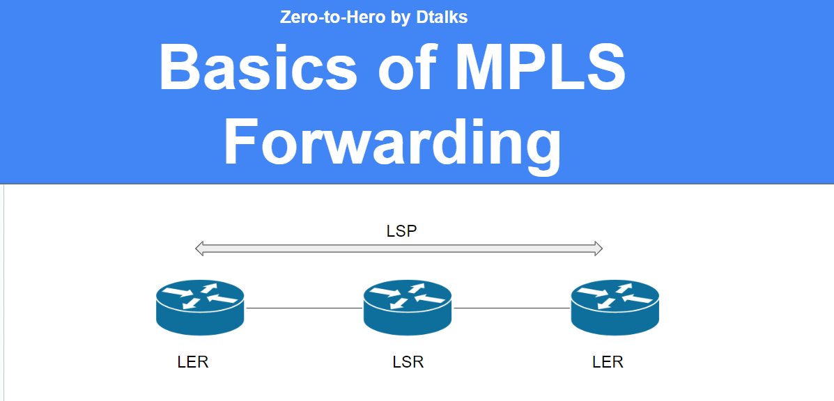
Now it's time to realize the most common and most using words in MPLS terminology that is "Label Switch Path (LSP)"
When it comes to mapping labels among routers, each router maintains a trackable mapping for every Forwarding Equivalence Class (FEC). This traceable mapping is referred to as the Label Switch Path (LSP). An LSP represents a one-way path, as demonstrated in the example.
The path from R1 to R4 constitutes a single Label Switch Path (LSP) for R4's router-id, specifically when its Forwarding Equivalence Class (FEC) matches the address 4.4.4.4 and the "Explicit-NULL" Penultimate Hop Popping (PHP) mode is in use.
When employing the "Implicit-NULL" Penultimate Hop Popping (PHP) mode, the Label Switch Path (LSP) for the Forwarding Equivalence Class (FEC) = 4.4.4.4 will encompass only the path from R1 to R3.
Also you can see that both Packet A and Packet B originate from two distinct subnets, yet they are destined for the same router. As a result, both packets must travel along a single Label Switch Path (LSP) route. This demonstrates how older routers managed to address the challenge of longest prefix matching using MPLS technology.
In the current year of 2023, major router vendors have adopted specialized computing chips in their line cards to handle longest prefix matching. This advancement enables routers to attain a remarkable forwarding efficiency of 1 trillion packets per second and reach speeds of up to 400 Gbps. Consequently, the advantages of using label switching in MPLS have diminished in today's context.
However, it's worth noting that cost remains an important factor. While modern hardware ensures efficient longest prefix matching, it also brings about significant expenses. More efficient hardware chips may contribute to higher costs per device.
Indeed, despite the advancements in routing technology, MPLS retains its position as the predominant access technology in Service Provider networks. This is primarily due to its robust capabilities in managing Virtual Private Networks (VPNs), implementing Quality of Service (QoS), and facilitating effective traffic engineering applications. These features make MPLS a preferred choice for addressing complex network requirements within Service Provider environments.
Certainly, we can delve deeper into various aspects of MPLS, including LDP (Label Distribution Protocol), MPLS Traffic Engineering (MPLS-TE), and MPLS VPNs (both Layer 2 and Layer 3) in future articles. These topics provide a comprehensive understanding of the intricate workings and practical applications of MPLS technology. Feel free to reach out whenever you're ready to explore these subjects further
Please send me suggestion and questions to below email
dakshina.s.hettiarachchi@gmail.com
(c) Dakshina S. Hettiarachchi