Hi to all. I need your help, because I've done lot of searching and haven't found any answer.
I'm planning to build a chip amp TDA2005R based on this schematic (see attached). But I have problems with designing PCB layout.
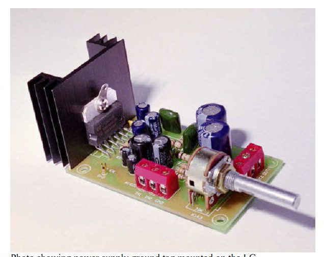
There are many PCBs on the net, but almost all of them are for mono or bridged mode. I need PCB for 2 channell mode (stereo). I have found a kit, that looks like this.
Maybe someone has a kit like this or can post here PCB layout for this TDA2005 in stereo mode.
Any help will be much appreciated.
Thanks
I'm planning to build a chip amp TDA2005R based on this schematic (see attached). But I have problems with designing PCB layout.
There are many PCBs on the net, but almost all of them are for mono or bridged mode. I need PCB for 2 channell mode (stereo). I have found a kit, that looks like this.
Maybe someone has a kit like this or can post here PCB layout for this TDA2005 in stereo mode.
Any help will be much appreciated.
Thanks
Attachments

You dont need layout for it,you can build it on breadboard
I would prefer to assemble the amplifier on compact self made PC board without any wire jumpers or so...
Thanks for the advice. )
Its a simple chip to use and there is a stereo schematic in the data sheet ....
Yes, there is a schematics, but I have problems with designing the PCB. (
Attachments

Last edited:
So, here what I've got. Schematic from datasheet, just added a 2200uF cap for power supply.
Are there any fatal "grammar" mistakes in this PCB? Can I use this layout?
Thanks.
Are there any fatal "grammar" mistakes in this PCB? Can I use this layout?
Thanks.
Attachments


Last edited:

So, here what I've got. Schematic from datasheet, just added a 2200uF cap for power supply.
Are there any fatal "grammar" mistakes in this PCB? Can I use this layout?
Thanks.
R4 may have to be mounted on the bottom of the board.
Nothing wrong with that, mind you.
")
2x20w is too powerful.
I'm planning to use this amplifier for my PC at work, and 2x6w is more than enough for my small 8ohm fullrange speakers. Sound quality is more important for me than the power.
Thanks for your help.
R4 may have to be mounted on the bottom of the board.
Nothing wrong with that, mind you.
Thanks a lot.
It's a good idea.Here are the final layout. I will attach the PDFs, so everyone can use this.
Attachments

Last edited:
2x20w is too powerful.
I'm planning to use this amplifier for my PC at work, and 2x6w is more than enough for my small 8ohm fullrange speakers. Sound quality is more important for me than the power.
Thanks for your help.
Having reserve power is all most always good. The extra cost is small, and this amp sounds very good.
I have to agree with brucetassin that having a maximum rated power that is more than you will use is a good idea. You will have the best sound quality that way, especially if you ever want to crank it all the way up to 6 Watts. If you design for a max rated output power of 6 Watts, then unless you are extremely careful about the power supply design the sound quality will probably suffer when you get anywhere near 6 Watts. In fact, to really get to 6 Watts, you HAVE to design for a somewhat-higher max rated output power. So rather than needing excessive reservoir capacitance, it's much better to simply start with a higher rail voltage. Design for x watts but then say that your amp is rated for x/2 watts, or something like that. But make sure that your transformer's VA rating is at least 2x VA.
Reservoir and decoupling capacitances can play a very large role in the sound quality. You need decoupling caps with controlled distances from the chip power pins, to get the transients (and feedback mechanism) to be accurate. And that will probably help determine the soundstage image quality.
You also need a small bypass cap, right AT the power and ground pins, for high-frequency stability. And it really does need to be within a couple of millimeters, or less.
Anyway, here is a very-simplified version of some of what you need to consider about reservoir caps:
http://www.diyaudio.com/forums/chip...ors-audiosector-lm3875-kit-5.html#post3549940
And here is a slightly more-informative discussion:
http://www.diyaudio.com/forums/soli...n-attempt-number-2-simpler-9.html#post3532280
And here is where much of it sort-of came from:
http://www.diyaudio.com/forums/power-supplies/216409-power-supply-resevoir-size-169.html#post3320547
But you can probably just use the attached spreadsheet.
Attachments
Just in case it might be useful, a while back I posted a spreadsheet that will SIMULATE a linear power supply with the worst-case load, with variable transformer ratings, reservoir capacitance, load resistance, rated output power, and basically everything else you need, which is attached to the post at:
http://www.diyaudio.com/forums/power-supplies/216409-power-supply-resevoir-size-167.html#post3287619
It uses a numerical solution of the differential equations for the circuit. So no approximations are used. But it doesn't take into account the efficiency of the amplifier. So you should probably multiply the desired output power by 1.5 or so.
The transformer it uses is scalable. So you can set the transformer parameters to whatever you want. But I don't know how well it will scale down to such a small VA rating, compared to that of the originally measured transformer.
A downloadable PDF file describing the spreadsheet, and the solution method, et al, is attached to the post at:
http://www.diyaudio.com/forums/power-supplies/216409-power-supply-resevoir-size-166.html#post3279883
However, if you ever really get into it, I would recommend using LT-Spice, since it's much more flexible and powerful. It's a free download from linear.com.
Last edited:
Gootee, Brucetassin... thank you for your help. It is appreciated highly.
Guys, you are definitely right; having power reserve it good. But now I have no appropriate transformer that can supply such power. What I have is a cheap Chinese ac-dc adapter with 13.5VDC and 1.2A. So, even if I wanted, this transformer simply cant give more than 5-6w per channel.
Gootee, I will read carefully the information that you gave. It will be very useful, I'm sure.
Please, look at this layout. I think it is much better, than the previous one. I tried to move the caps you mentioned as close to power pins, as possible.
Attachments

Maybe I'm reading it wrong, or maybe I didn't describe it clearly. But I meant close to the chip's power pins, not the board's power input connector. Sorry about that.
My bad, I didnt read carefully.
Here it is.
Attachments

What I have is a cheap Chinese ac-dc adapter with 13.5VDC and 1.2A. So said:This should work good and gives enough power.
12.6V CT 3.0A Chassis-Mount Transformer with Leads : Transformers | RadioShack.com
Dear davidus, I'm quite certain that the layout is *electrically* fine (didn't really check it though) but there's a *practical* problem with it: you need the back side of the TDA2005 free for the heat sink .
1) you put R4 there.
2) even if you put it below, as suggested, the chip back is still too far away from the PCB edge, complicating *a lot* heatsink mounting.
If you put the heatsink on top of the PCB, how will you mount it?
And heatsinks are, by definition, heavy; if all that holds it there are the TDA2005 legs, they will soon crack.
My (and all commercial ones) design puts it right on the edge, so it can be bolted to a chassis mounted heatsink or an aluminum back panel.
I use it bridged, but for Stereo PC speakers fed from nominal 12V supplies , I use a dual TDA2003 PCB (a TDA2005 is basically 2 x TDA2003 inside the same case).
When I get a camera I'll post a couple pictures
- Status
- This old topic is closed. If you want to reopen this topic, contact a moderator using the "Report Post" button.
- Home
- Amplifiers
- Chip Amps
- TDA2005R stereo application PCB layout