I am adding 6924 circuit boards to my layout to reroute power for engines whose pickup rollers are too close, The power routing requires soldering a wire to each closure rails. I am having difficulty soldering a wire to these rails to run back to the circuit board. I have tried several different solders with and without flux without success.  Is there a coating on these tracks that makes soldering difficult if not impossible? The directions for installation of the wires to the circuit board are clear and require soldering?


Thanks for your replies


skcaseydog1@gmail.com


Original Post

Replies sorted oldest to newest

Hello,


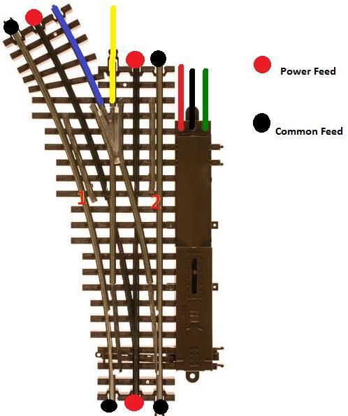
If you are using 3r track and your turnout is wired like in the example below, you do not need to power the closure rails. I have run a K-Line porter though an AtlasO O-54 turnout with no problems, so I believe you either have some wiring issues with the turnout or with the locomotive. Remove the turnout from the layout. Examine the outer rails of your turnout (marked 1 and 2 below.) They should be one solid piece. If each rail is made of multiple pieces, ensure all of the pieces are tied together electrically. Add power drops as indicated below and add enough track to each entrance of the turnout so your locomotive can clear the turnout. Run your locomotive through the turnout in all directions. If your locomotive stops, cut the power to the track and look to see where the pickups are located.  


noclosurerail


In reference to soldering wire to the rails, I solder my wires to a rail joiner and then place where needed. The rail joiners are easy to bend in order to fit around the rails.


Attachments

Images (1)
  • noclosurerail
Thank you for your thoughtful reply. While I agree with your comments, larger Atlas turnouts, 72 to 54 and plain 72 have a large gap in the contact for rollers on engines that are less than 4 inches. This condition requires use of Atlas 6924 circuit board and power rerouting and installation of electrified non derailing also through the same circuit board.

The other turnouts on my layout (54 and smaller to 42) work fine.

It is essential the a Additional wire to the circuit board comes directly from the closure rail at the end that moves across the smallest radius and the metal of the track does not hold solder.

Thanks for your interest

Jaagslinerr

Four connections (2) input to the 6924 relay board, and (2) power routing to the dead rails center of switch.  I have a Weller 100/140 soldering gun and a Weller D550, (old, and very hot) 250/325 watt soldering gun.  The Weller 100/140 should do this project with 60/40 flux core solder.  Kester SN60PB40 1.2mm (.050")

(1.) Attempt to clean/or scuff the rail,(bottom flange), where you want to attach solder. Scrape with a small screw driver blade or knife to remove surface material/shine.

(2.) Touch the gun to the bottom flange of the rail where you wish to attach the wire.

(3.) Apply heat and solder until the solder flows out on the rail flange.  A concave look is very good.  A convex/bead look is poor. 

(4.) Remove heat and let cool. 

(5.) Apply solder to the tip, (about 1/8" to 1/4"), of the wire to be attach in the same manner as steps (3.) and (4.).

(6.) Holding the wire, with a small screw driver, to the solder, already applied to the rail, reheat the wire/and rail with the soldering gun until liquid. Be careful, too much heat, for too long, will soften the plastic.

(7.) Still holding with the small screw driver, remove heat and let cool until solid.

(8.) When cool test by attempting to remove the wire , cold with a screw driver. A good solder joint should with stand an attempt at mechanical separation.


(2) input wires are non-derail auto-switching.  Needs to be an isolated section, check to be sure the small outside rail sections are isolated from the frog.  Note the pieces of styrene. Sometimes the small pieces touch the frog which is a problem.  

 One of the(2) Power Routing wires attached to the dead rail sections of the switch.

Last edited by Mike CT
Mike

Thank you VERY much.

Steve

If you want to see a really good shop we should take a ride to Ambler PA Bussingers Trains.

Then a second Place is Nicholas Smith in Broomall PA, A third place is Just Trains in Delaware just off turnpike.

Then once we figure out what you like, then we go to reputable people on Internet.

Trubee was great yesterday. You missed a good time. But I understand, too much of a good thing can be annoying!

Talk to you soon

There is also the "screw it" method for those of us -- like me -- who don't seem to be able to make soldering wire to Atlas track work even with the right solder and gun. You drill a small hole in the side of the track, insert the wire and anchor with a tiny machine screw. I tailored that to my own skill level and like the way it works. Can provide you with more details if you are interested.

Forum member Ingeniero No1's build thread contains info on powering Atlas track without soldering, Probably similar to what Scott is talking about above.

Here's a link to the build thread:  Hidden Pass Junction RR


On page 2, scroll down to the post dated May 1, 2011 9:06 AM and you will find it. It works great, I used it on my layout and everything works very well. Just glad I found this before starting my permanent layout and thankful that Ingeniero No1 shared the info in his build thread. Very easy to make changes this way as well.

Add Reply

Post

OGR Publishing, Inc., 1310 Eastside Centre Ct, Suite 6, Mountain Home, AR 72653
800-980-OGRR (6477)
www.ogaugerr.com

×
×
×
×
Link copied to your clipboard.
×
×