25 minute read
Back to basics – Points Part 1 of 2
by The PWI
Next Article
The following is an edited version of an article originally published in IRSE News. It is published in the PWI Journal with the kind permission and co-operation of the IRSE. This article provides an insight into points, ie a pair of switch rails fitted with Point Operating Equipment. It is taken from the latest in a series of “Back to basics” articles by the Institution of Railway Signalling Engineer’s (IRSE). This artcile is aimed particularly at helping people preparing to take Module A of the IRSE’s Exam, but it will also be helpful to those people who are new to the rail industry. The article is in two parts, the second of which will follow in the next issue of the PWI Journal.
AUTHOR: Francis How, with contributions from John Alexander and Trevor Bradbeer
There are seemingly endless varieties of points and point operating mechanisms around the world, and it is not possible to cover them all. Instead, the focus will be on the principles and common practices, with some examples. Terminology varies considerably as well; the term ‘points’ will be used throughout, but points are also referred to as ‘switches and crossings’ (S&C) and ‘turnouts’.
Signalling & Telecoms (S&T) and Permanent Way engineering both embrace a broad range of engineering skills. Many articles in IRSE News explore high-tech topics such as software, IP networks, cyber security and artificial intelligence. At the other end of the spectrum lies the mechanical engineering of points, with the signal engineer quite literally involved in the nuts, bolts and grease of keeping points operational. Some S&T engineers can work right across this spectrum, and there are many with more specialised roles. What are points and why do railways need them?
As soon as a railway becomes more than a simple piece of track connecting A and B, requiring junctions to connect with other lines or sidings, then points are a necessity. They comprise fixed and moveable rails that guide a train from one track to another. Roads have junctions as well, of course, but self-evidently there are no moveable parts, and it is worth briefly considering why railways are not the same. Firstly, road vehicles can steer themselves whereas trains cannot, and they therefore require something to guide them in the intended direction. Secondly, the wheels of road vehicles sit on the road surface, with no part of the wheel below surface level. The wheels of railway vehicles have flanges, which is the part of the wheel which runs on the inside of the tracks and serves, in extremis, to prevent the vehicles derailing – see Figure 1. For these reasons, points have moveable sections of rail, both to provide a continuous railhead for the train to travel in the intended direction, and to provide gaps in the rails where required so that the flanges can pass through.
On most railways, the points trackwork is the responsibility of the track (permanent way) engineer, and the signal engineer is responsible for providing and controlling, (via the signalling system), the means of moving the points, and for ensuring that the points are in the required position before a train is permitted to pass over them. This division of responsibility is not universally true however, and in some railway administrations the roles and responsibilities are allocated differently.
Points are used to enable trains to diverge from the ‘straight’ route ahead, onto another line, or to stay on the straight route. When trains traverse a set of points in this manner, they are said to be travelling over the points in the ‘facing’ direction. Points can also be used in the opposite direction, of course, where two lines converge and become one. Trains using points in this manner are said to be travelling over them in the ‘trailing’ direction – see Figure 2. Many points are used for both facing and trailing movements.
THE BASIC DESIGN OF POINTS
Before going much further, it is necessary to understand the principal parts of a set of points. The main components are shown in Figure 3. Again, terminology varies somewhat, both from one country to another and between the disciplines of permanent way engineering and signal engineering.
Various terms are also used to describe the position of points. In Britain, and in some other countries, when the points are set for straight route they are said to be in the ‘normal’ position, and when they are set for the diverging route, they are in the ‘reverse’ position. This terminology dates from the days of mechanical lever signal boxes, when a lever was said to be in its normal position when it had not been pulled, and in its reverse position when it had been pulled. Alternative terminologies for normal and reverse, which are used in other parts of the world, include left/right, positive/negative and direct/diverted.
The key components of the points shown in Figure 3 are:
• Switch rails (also known as blades or tongues) are the movable rail sections which guide the train along the straight or the diverging route. They are tapered at their tips so as to fit closely to the adjacent stock rail.
• Stock rails are the outer running rails for the straight and diverging routes. The tips of the switch rails move up tight against the stock rails when in the closed position for the route set.

Figure 2: Facing and trailing directions of movement over a set of points.
• Common crossing, (also known as a ‘Frog’ or ‘Vee’ crossing), is the part of the track layout where the paths of the wheel flanges converge. Of necessity, there is a gap in the rails here so that the wheel flanges can pass through. The existence of a gap can however create problems, particularly on long turnouts, and this subject will be explored further in Part 2.
• Closure rails, (also sometimes referred to as ‘lead rails’ or ‘belly rails’), are non-moving sections of rail that connect the switch rails with the common crossing.
• Cover check rails. These are short sections of rail positioned alongside the stock rail to ensure that the wheels follow the correct route through the common crossing (frog). , (ie they
‘cover’ the gap in the crossing). It can be seen in Figure 3 that there are similar rails alongside and forming part of the common crossing. These are known as wing rails, and sometimes these are manufactured as part of the common crossing rather than being separate rails.
• Stretcher bars are provided at intervals between the two switch rails to help ensure that the correct distance is maintained between them, not just at the tips but throughout their length.
Note that railways in many countries do not use stretcher bars, although they are used in Britain and some other countries whose railways are based on British practice. Where they are provided, the number of stretcher bars is governed by the length of the switch rails, which in turn is determined by the maximum permitted speed of trains taking the diverging route.
• Switch heels are the demarcation point between the movable switch rails and the fixed closure rails. A heel block assembly is normally positioned in the vicinity of each heel to maintain the switch, closure and adjacent stock rail in the correct relative positions, although some modern configurations do not require this.
All these components work together to guide a train along the correct route. Ensuring that a train can traverse points safely and smoothly, with minimum wear and tear on both the wheels and the track, means that the design of points is a complex matter, particularly where points are very long (for high-speed turnouts).
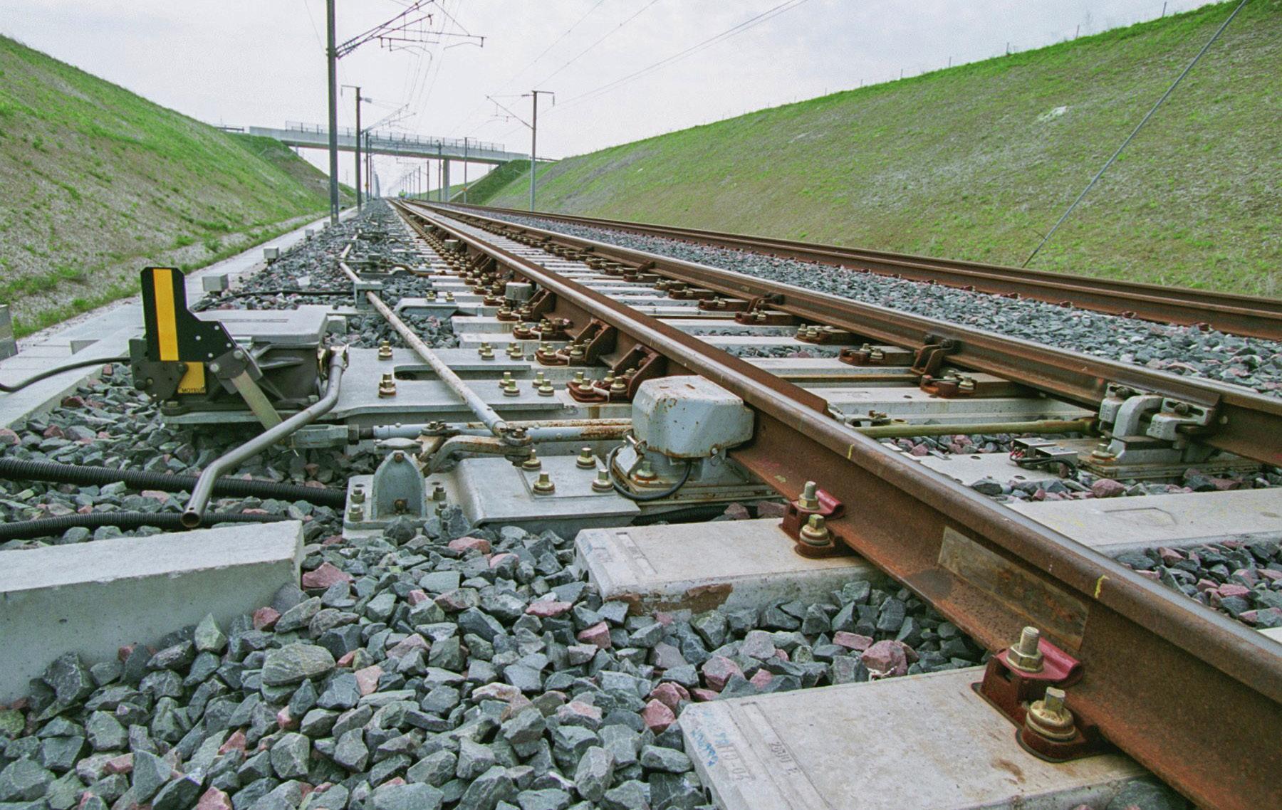
What Figure 3 does not depict, but which can be seen in Figure 4, are the supporting elements for the rails. These include extralong sleepers which support the rails. Sleepers are known in some parts of the world as bearers, ties or cross ties. Where ‘flat-bottom’ rails are used they sit on ‘baseplates’; similarly ‘bullhead’ rails sit on ‘chairs’. Note that some types of modern points utilise concrete bearers which do not require either baseplates or chairs for the ‘fixed’ (ie non-moving) rails. (Similar configurations are used also used to support rails in plain line). Where the switch rails move, the baseplates or chairs support both the stock rail and the switch rail. These are ‘slide chairs’, and as well as holding the stock rail in position they also have a flat surface over which the switch rails move laterally. To aid movement, these surfaces are usually lubricated, or fitted with special inserts to reduce friction, or with rollers which lift the switch rails very slightly while they move.
OPERATIONAL HAZARDS ASSOCIATED WITH POINTS
Thus far, the methods for moving points and holding them in position for the passage of a train has not been described, but this is where the signal engineering discipline applies. Firstly, however, the operational hazards associated with a set of points should be considered. Clearly, a section of rail that can move is potentially disastrous for a train, and the principal hazards are as follows:
1. Points not fully in correct position for the safe movement of a train. For facing movements, this is likely to result in derailment.
For trailing movements derailment is unlikely, but damage may occur to the points or associated trackside equipment
2. Points in the opposite position to that required for safe movement of a train. For facing movements, this will result in the train going on the wrong route, which may have consequences such as derailment as a result of excessive speed, or collision with another train. For trailing movements, the train might derail or, more likely, severe damage is caused to the points and the associated trackside equipment.
3. Points moving as a train passes over them. For facing moves, this is very likely to result in derailment of all or part of the train.
For trailing movements, it could result in derailment but is more likely to cause damage to the points and associated trackside equipment.
4. Excessive speed. This may result in derailment. Most points have, by their very nature, one position which involves a relatively tight radius curve, corresponding to the diverging route. There is generally no super-elevation or ‘cant’ on the diverging route through the points to help the train negotiate the curve, (unlike plain line curved track).
5. Track gauge is incorrect for safe movement of a train. This is likely to result in derailment. The fact that part of the track is moveable means that there is a somewhat greater risk, (compared with plain line), of the track becoming ‘wide to gauge’ because of lateral outward movement of the rails caused by the passage of successive vehicles or trains.
6. Broken and worn rails. This may result in derailment. The switch blades and the common crossing have less metal to support the wheels, and both the switch tips and the crossing receive more impact from the wheels, which may cause rails to break. Switch and stock rails also wear through use, especially where heavy traffic uses the diverging route. Excessive wear can lead to derailment.
7. The risks associated with the first three of these hazards are controlled principally through the signalling system, of which more information follows shortly.
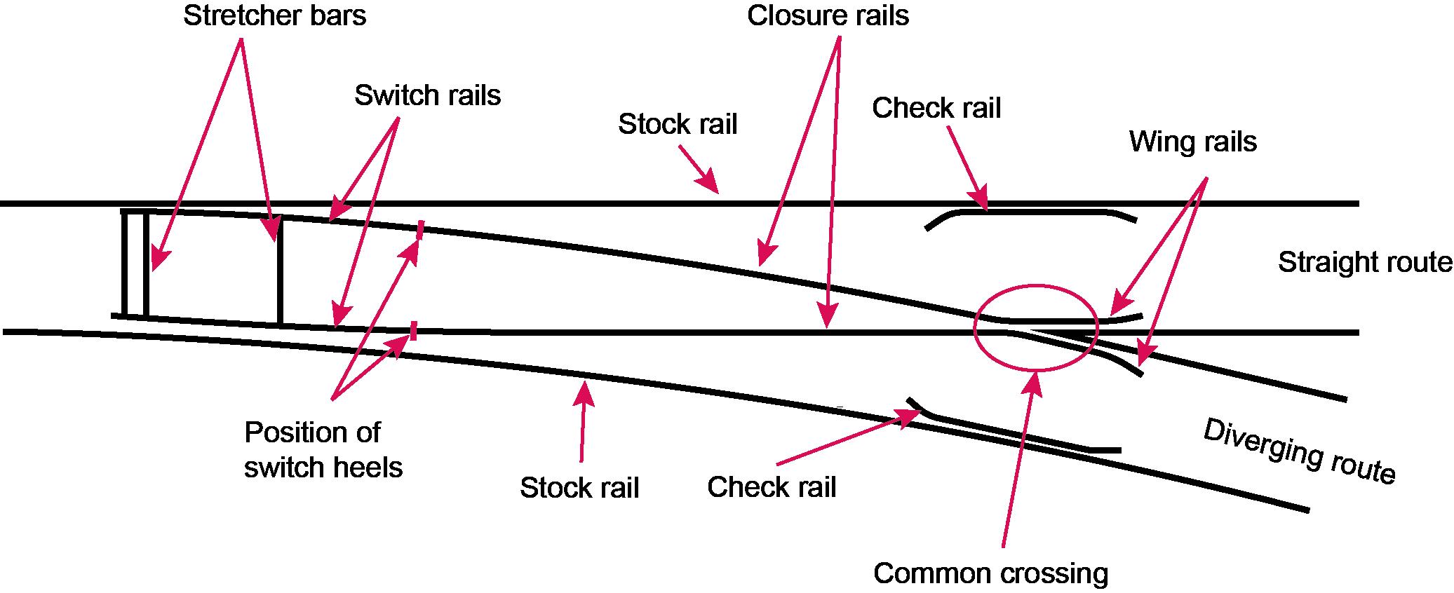
Figure 3: The principal parts of a typical set of points.
Figure 4: General layout of a set of points. (Image: Shutterstock / Timofeev Vladimir).
Extended sleepers (bearers)
Stock rail
Switch rail Switch rail
Stretcher bar
Slide chairs
Stock rail
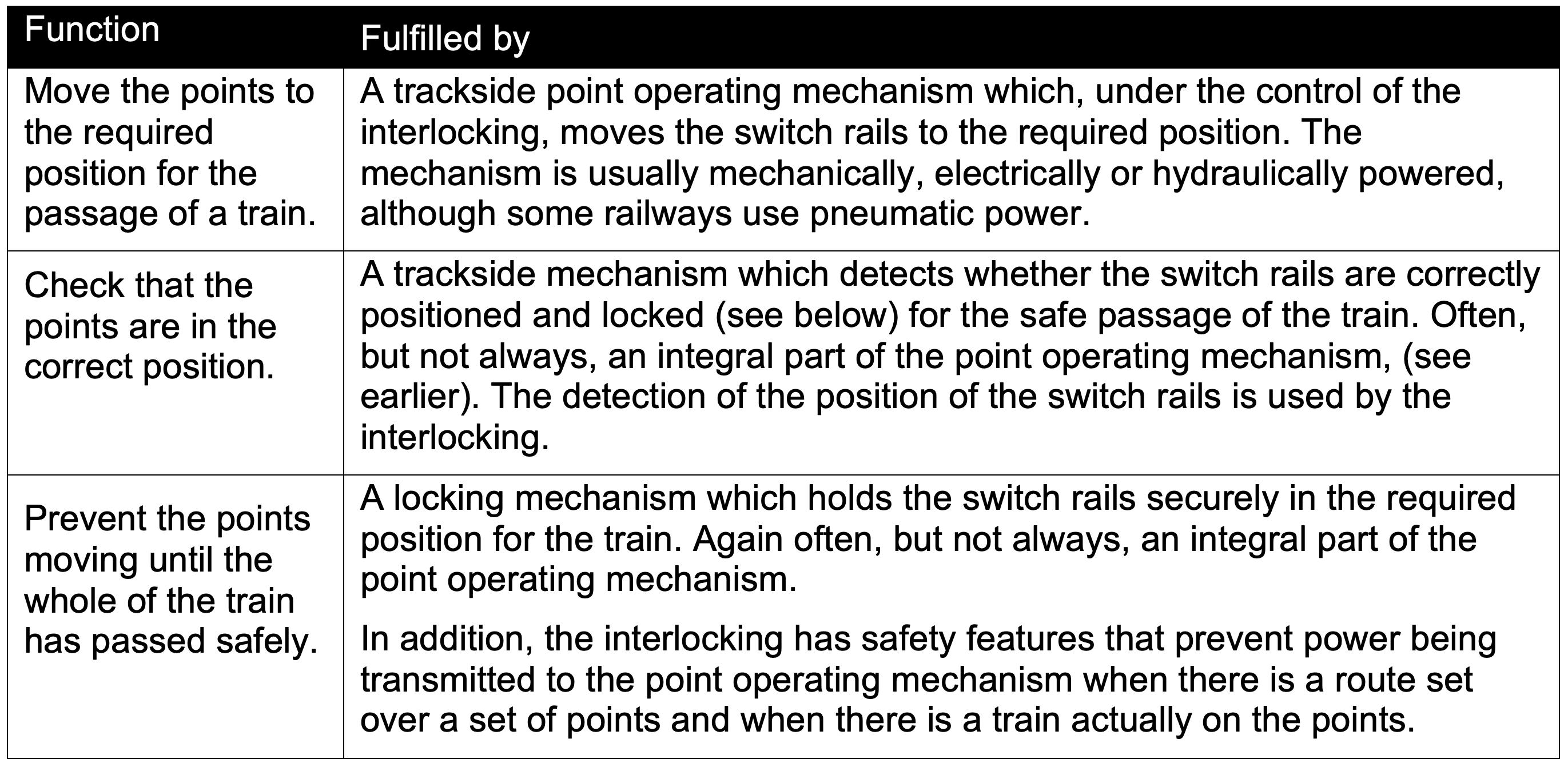
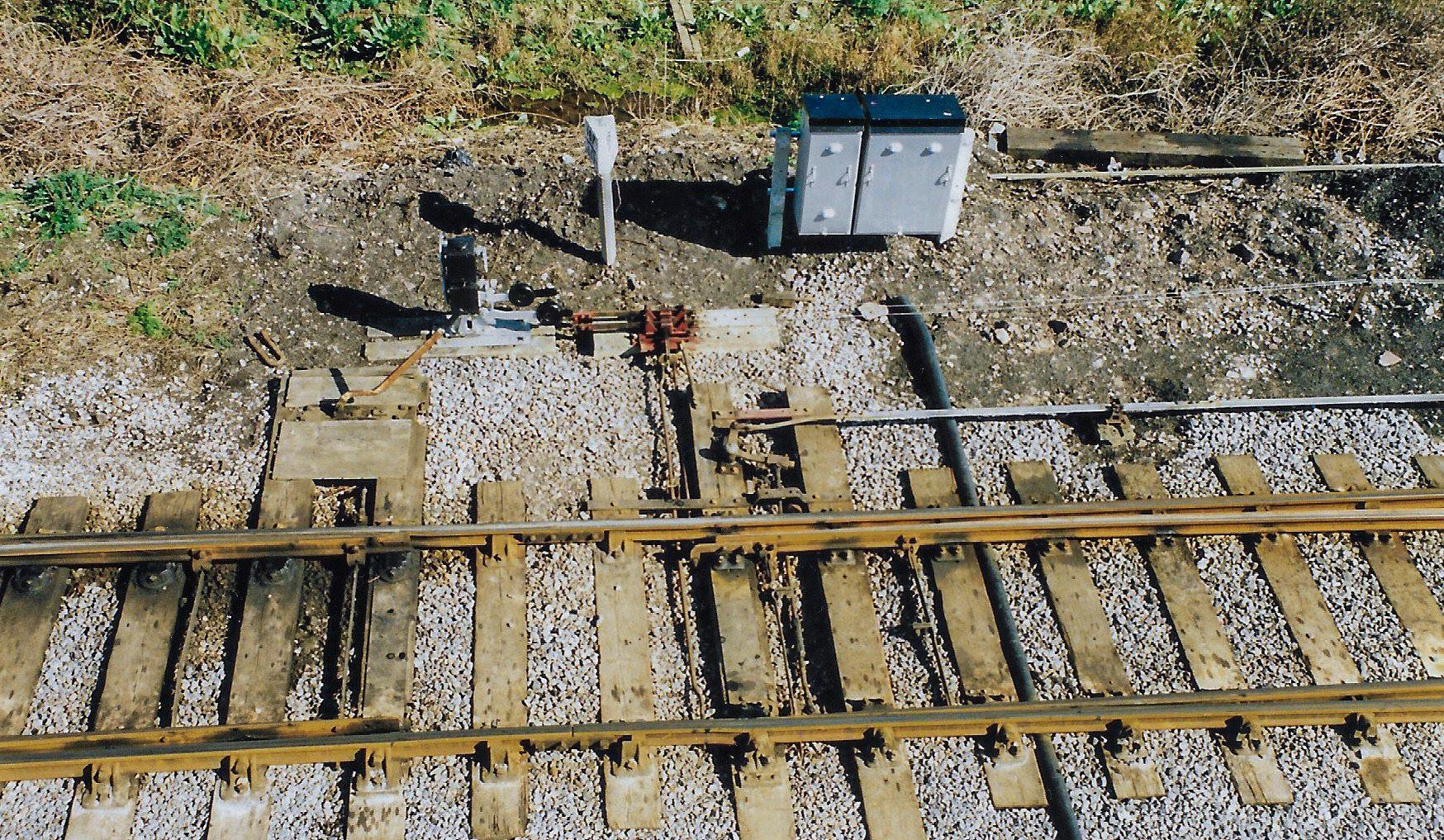
Figure 5: Points rodding leading from the signal box, (out of picture, to the right) to a set of points, with cranks that are used to transmit the motion of the rods through a right-angle. (Image: John Francis).
The fourth hazard is usually controlled by a speed restriction that applies to trains taking the diverging route, reinforced by controls in the signalling system. These controls may include route and/or speed indications and aspect controls that instruct/remind the driver to slow down, and train protection systems which enforce speed reduction in the event of driver error.
The risks relating to the fifth and sixth hazards are controlled principally through track inspection and maintenance.
THE ROLE OF SIGNALLING IN POINT OPERATION
The role of signalling in the operation of points is to fulfil three basic functions, and they are achieved jointly by the interlocking and the trackside equipment, as described in Table 1.
The interlocking features relating to points were described in two previous ‘Back to basics’ articles (IRSE News, April and May 2020), and it is not the intention to repeat them in this article. This article focuses instead on the trackside signalling equipment that moves, locks and checks the points.
POINT OPERATING MECHANISMS
MANUALLY OPERATED POINTS
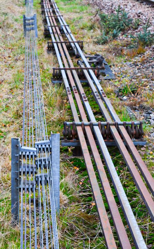
When railways first began, the practice was for railway personnel to operate a set of points using a lever beside the track. Examples of this can still be found in sidings. When signal boxes began to appear, the points were operated by moving a mechanical lever in the box. Each point lever was connected via rodding, (or sometimes wires), and cranks to the tips of the switch rails of the associated set of points, (see Figures 5 and 6).
By pulling the lever to the reverse position in the lever frame, the rodding moved in one direction sufficiently to move the points into the reverse position. Restoring the lever to the normal position returned the points to the normal position.
Because of the weight and the effort required to move the rodding and points via the points lever, the distance from a signal box to a mechanically worked set of points is quite limited (typically ~200-300 metres).
Examples of mechanically-worked points can still be found in many parts of the world, but all modern signalling systems use poweroperated points. Most commonly this takes the form of an electric motor in what is known as a point machine, (also known as a switch machine or switch motor). The point machine is located adjacent to the switch blades and is connected to the tips of the blades either by two rods, (one for each blade), or by a single rod and a bar which links the two tips, ensuring they move in synchronism. The bar is commonly known as a ‘lock stretcher bar’. Figure 7 shows a point machine, with the drive rod connecting the electric motor via gears to the blades. As the motor turns, the rod moves to the left or the right, moving the points to the normal or reverse position respectively. Note that there are other rods also shown in the diagram, the purpose of which will be discussed shortly.
There are many types of point machine in use, with various drive arrangements linking the motor to the switch rails. That shown in Figure 7 is just one example. A layout in a training environment is shown in Figure 8, where the point machine is mounted on extended sleepers (bearers), and as with mechanical points a soleplate, (extended stock rail gauge tie), maintains the gauge and the distance between the track and the point machine.
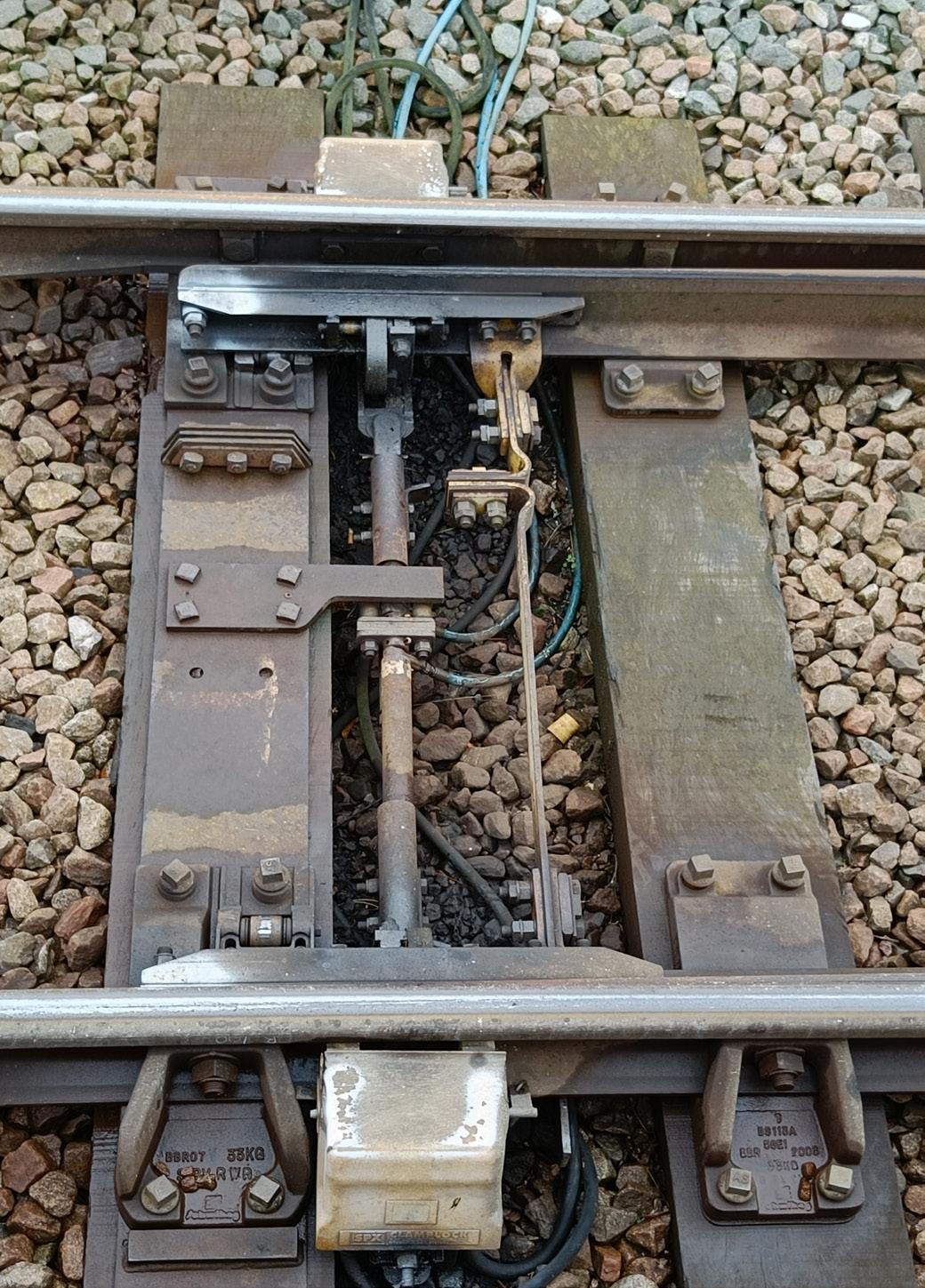
Over the years, alternative types of powered point operating mechanisms have been produced. Some use hydraulic actuation, such as the clamp lock, (other similar devices are known as chair locks, claw locks and ground locks). The clamp lock has a hydraulic power pack instead of an electric motor, with hydraulic rams, (jacks), positioned between the sleepers to drive the switch rails to the normal and reverse positions.
A further variant is the ‘in sleeper’, (also known as ‘in bearer’), mechanism, where all the machinery is contained within a box or trough which takes the place of a conventional sleeper. This means there is little or no equipment above sleeper level, thus making it easier to undertake mechanised track maintenance without risk of damage to the equipment. It is also worth mentioning an example of an innovative approach to point operation which has featured in IRSE News, (most recently in May 2019). “Repoint” was a project undertaken by the University of Loughborough (UK) to consider afresh the failure modes of points and to develop an operating mechanism that was more reliable, just as safe, and would help improve track capacity. It illustrates that innovative thinking still has something to contribute to an issue as basic as point operation.
CHECKING THAT POINTS ARE CORRECTLY POSITIONED
The second signalling function associated with points, (listed in Table 1), is to detect the position of the points. This is necessary because it cannot be assumed that the points will move to the position to which they have been called. Ballast or other debris could obstruct the movement, for instance, preventing the switch rail closing against the stock rail. A power failure or malfunction of the point operating mechanism could also prevent the movement. In the situation where the points do not need to be moved for the route being set, it cannot be assumed they are still safely in the correct position for the next train. The passage of the previous trains might have caused the points to open very slightly, through vibration, wear or mechanical failure for instance. It is therefore necessary to check (and report), that the points are correctly positioned. This process is known as ‘detection’.
HOW DETECTION WORKS
The positions of both switch rails are detected, firstly to be sure that the tip of the closed switch rail is sufficiently close to the stock rail that a wheel flange could not pass between the two rails; and secondly to be sure that the gap between the stock rail and the open switch rail is sufficient for the wheel flanges to pass through.
In the case of point machines, detection is achieved using rods that are attached to the tips of the switch blades, which operate electrical contacts in a detector box adjacent to the track as the switches move left or right. In many point machines, the electrical contacts are inside the point machine rather than being a separate unit – see
Point machine
Drive rod Stretcher bar
Extended sleepers
Circuit controller and detection contacts
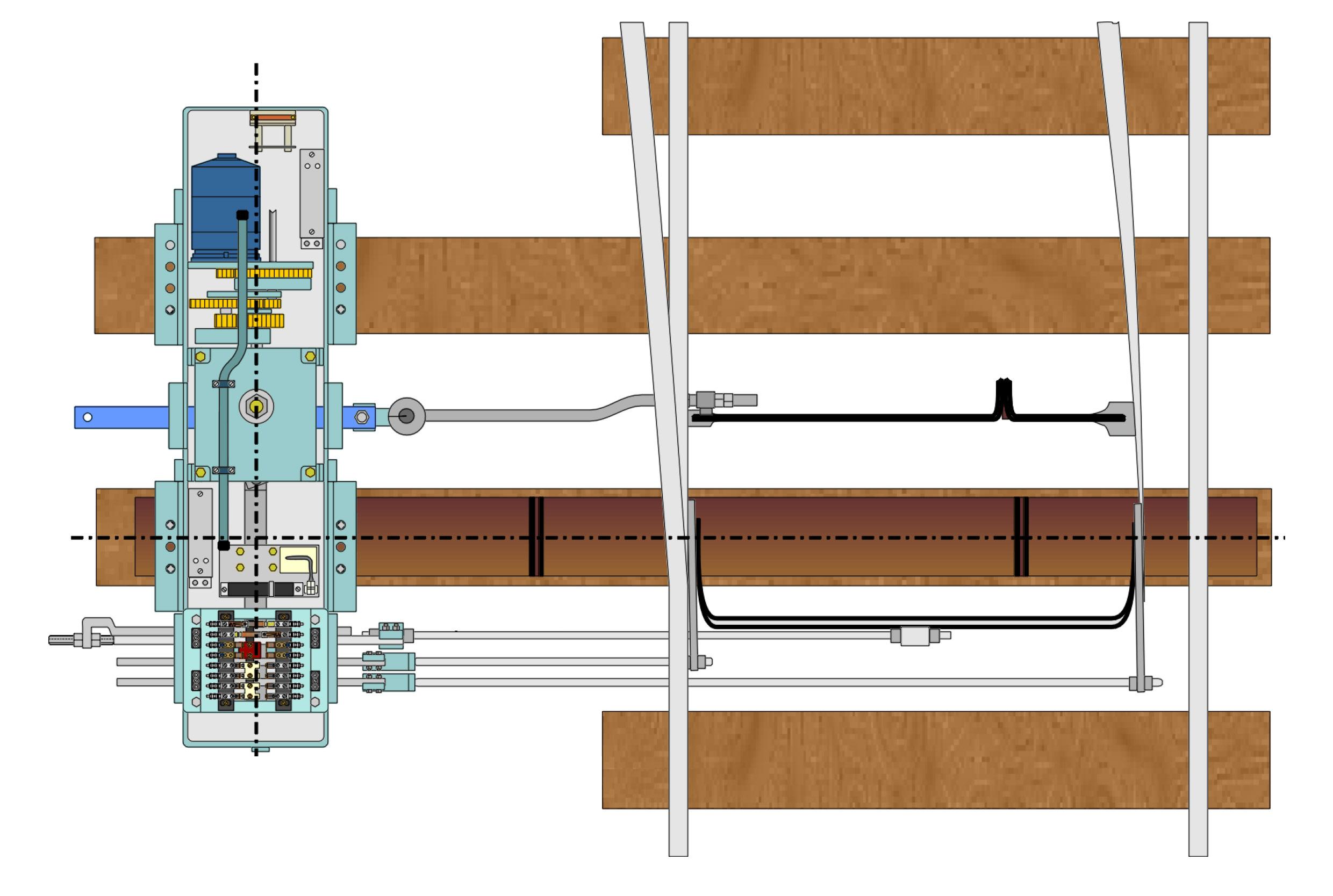
Facing point lock rod Detector rod (left hand switch) Detector rod (right hand switch) Sole plate
Lock stretcher bar
The electrical contacts for both switch rails are combined into points detection circuits, the outputs of which are fed back to the interlocking via fail-safe relay circuits or a high integrity transmission system. Hence the interlocking knows whether the points are normal, reverse or in an indeterminate state, (neither normal nor reverse). Where points are worked mechanically via rodding, a wholly mechanical detection system is often used. The detection rods are connected to sliding metal plates which engage with similar slotted plates at right angles which are connected to the wires that operate the mechanical signals. This ensures that the wires leading to the signals cannot be operated unless the points are correctly set, and vice versa. Hence there is direct interlocking of points and signals at the trackside, in addition to the interlocking of the levers in the signal box. An example of such a device is shown near the top left of Figure 5.
DETECTION TOLERANCES
The permissible gaps between the switch and stock rails vary slightly from country to country, but on a standard gauge railway the gap on the closed switch rail side must typically be no more than ~5mm, and on the open switch rail side it must be at least ~115mm, (these figures may also vary depending upon the type of points and operating mechanisms). If these criteria are not satisfied, the detection circuits will indicate to the interlocking that the points are not correctly positioned. Tolerances are generally assigned to these values, both to allow some latitude when setting up or maintaining the points and to reduce the risk of the closed switch detection being intermittently lost due to track vibration or slight movement. Thus, for instance, one railway administration states that the closed switch detection contacts must just be made at a switch-stock rail gap of 4mm (but not less) and definitely broken at 6mm.
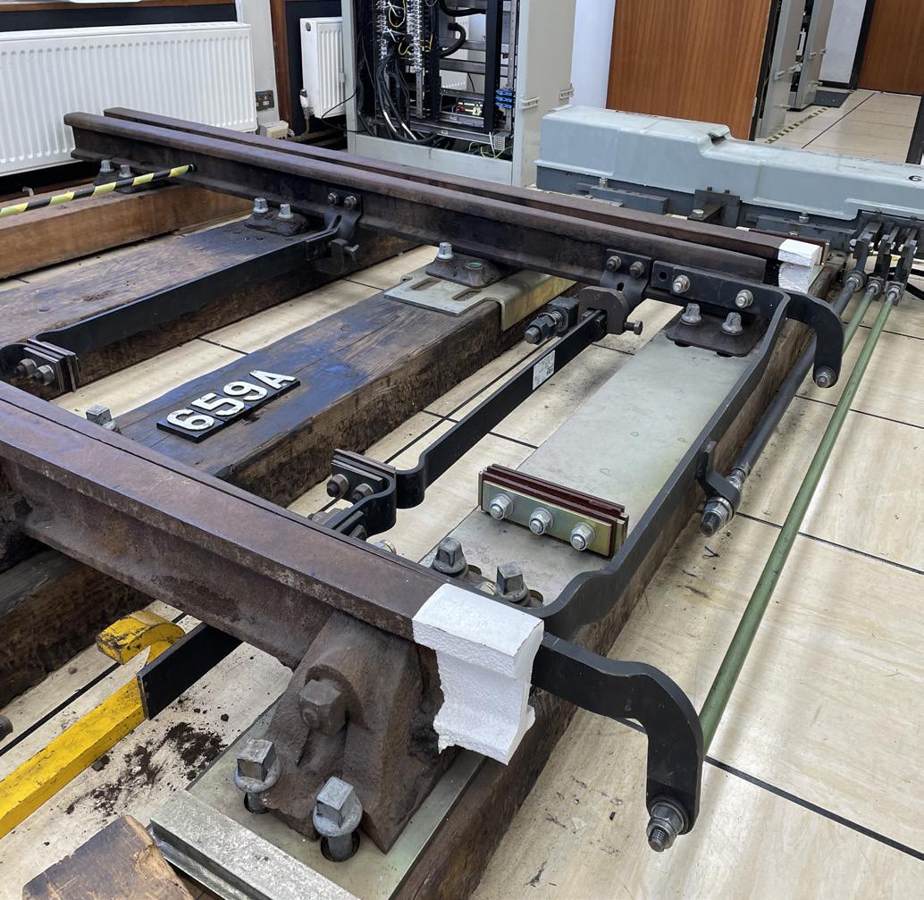
Figure 8: A typical point machine arrangement (in a training school environment) showing the drive rod, detection, FPL rodding connections, and associated stretcher bars. (Image: Trevor Bradbeer and Signet Solutions).
Detection of the open switch may at first sight appear to be less critical than the closed switch, but there have been accidents such as at Kingham (1966) and Grayrigg (2007) , both in Britain, where the open switch rail gap was insufficient. The continual battering by the backs of wheels caused the open switch rail and fittings to be fatigued, causing fractures leading to derailment. The condition of the stretcher bars was implicated in both accidents.
LOCKING THE POINTS IN POSITION
The third and final signalling component of points operation is the physical locking of the points in the required position, to minimise the risk of the switch rails moving. The locking mechanism is known as a ‘point lock’ or ‘Facing Point Lock’ (FPL).
In Britain it has been, from relatively early railway days, a legal requirement that points used by passenger trains in the facing direction are fitted with a lock. The Board of Trade’s 1892 requirements relating to the opening of new railways stated that “In order to ensure that the points are in their proper position before the signals are lowered, and, to prevent the signalman from shifting them, while a train is passing over them, all facing points must be fitted with facing-point locks…”.
This leads to two key observations. Firstly, the requirement recognised that points traversed in a facing direction present a much greater hazard than in the trailing direction; and secondly, the hazard was originally perceived more in relation to signalman error than the points having an excessive gap between the closed switch and stock rail because of poor adjustment, track movement or wear and tear. The risk of signaller error in relation to points movement has now all but disappeared as a consequence of comprehensive interlocking of points, tracks and signals. However, the requirement to lock facing points on passenger lines remains in most countries in the world and serves to minimise the risk of derailment in the vicinity of the blade tips. Furthermore, in practice many railways lock the points for movements in the trailing direction as well as facing, and also lock points on freight-only lines.
The extreme dangers associated with facing points can be seen throughout the history of railways. As with so many safety features on railways, accidents led to the introduction of facing point locks. In Britain there was for many years an aversion to having facing points at all, something which reached its height in 1873 when a north-bound express train derailed on points at Wigan station. Thirteen people died as a result of the points moving under the train (not, in this case, by the action of the signalman but because of the excessive speed of the train). The accident brought to the fore the need to fit locks to facing points. Even in relatively modern times points-related accidents have still occurred. Examples include Potters Bar, UK (2002), Grayrigg, UK (2007) and South Carolina, USA (2018). As with detection, the facing point lock mechanism varies in design for mechanically-worked and power-operated points. It is instructive to start by looking at mechanical points – see Figure 9. A lock stretcher bar connects the two switch blades. It has two slots cut into it. When the points are in the required position, the signaller pulls the FPL lever. This is a separate lever, not the same one as is used to move the points. The lever is connected via rodding to the lock rod, driving it into one of the two slots in the lock stretcher bar. There is one slot for the points in the normal position, and a second for the reverse position.
It can be seen that when the lock is engaged in one of the slots, it is impossible for the switch blades to move, either by the signaller attempting to move the points lever or by vibration as a train traverses the points. Figure 9 also shows the metal soleplate, (also known as the stock rail gauge tie), on which the lock and the two slide chairs are rigidly mounted to prevent movement and maintain the correct gauge at the switch tips.
Moving on to power-operated points, although some railways use point locks which are actuated by a mechanism separate from that which moves the points, more commonly the lock is part of the point operating mechanism. In the case of point machines, the lock is usually contained within the machine. It can be seen in Figures 7 and 8 that one of the rods coming out of the point machine is connected to the mid-point of the lock stretcher bar. Inside the point machine the rod is connected to a lock mechanism. As the point machine completes the point movement, (either normal or reverse), it engages the lock mechanism, so preventing the rod, lock stretcher bar and switch blades from moving until the point machine is powered up again to move the points to the other position.
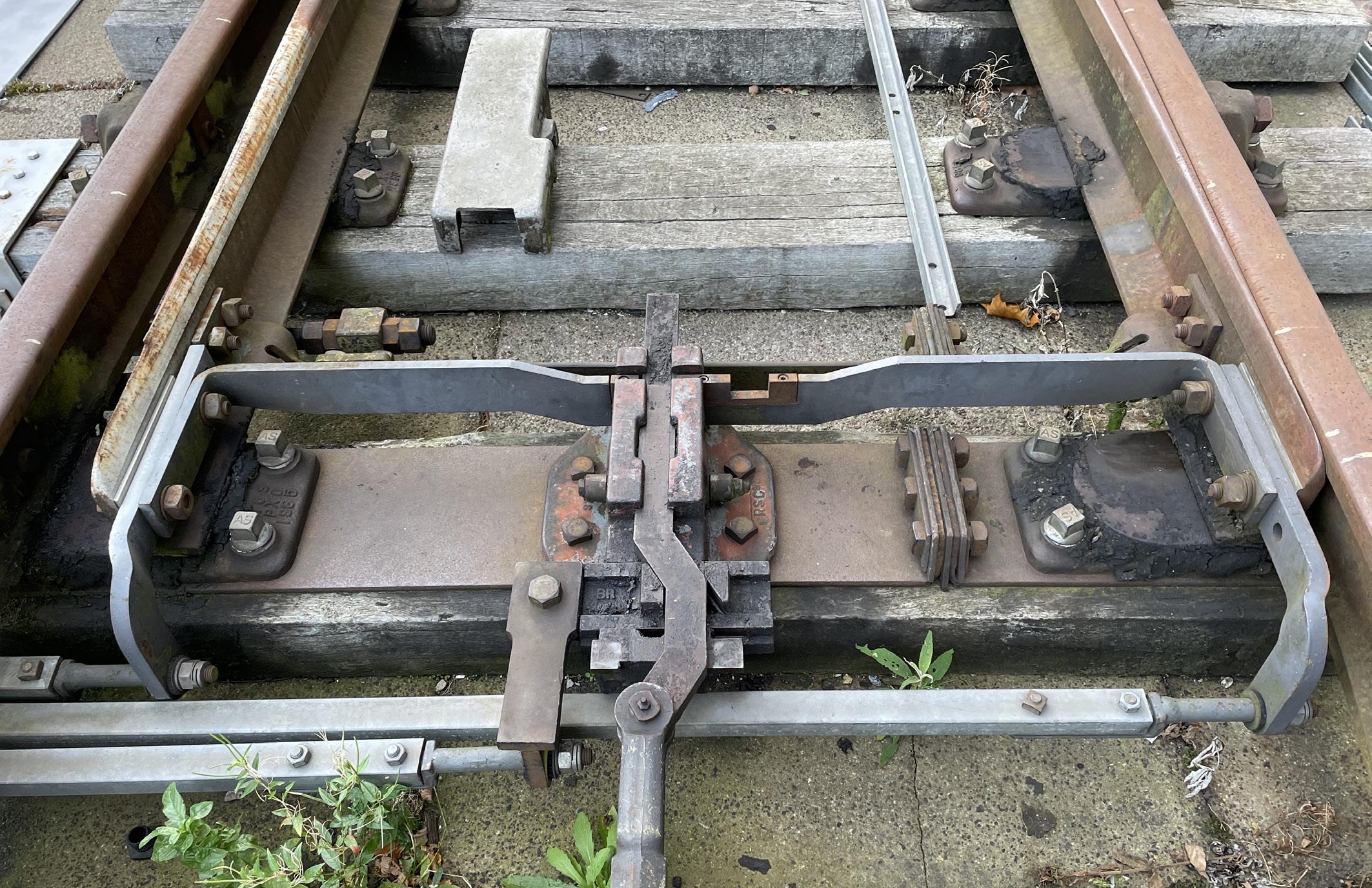
In the case of a clamp lock, the locking mechanism is different, although its purpose is the same. It is not simple to explain how a clamp lock works – it is easier to understand by seeing one in action. In essence, there is a G-shaped lock arm, (sometimes called a claw), attached by a pivot to the inside of each switch rail. The hydraulic rams move the switch rails via the drive/lock slides and the lock arms, and eventually the free end of the lock arm on the closed switch side is forced up so that it fits tightly against the outside of the stock rail. The switch and stock rails are thus physically clamped to each other and cannot be moved unless the clamp lock is powered to the opposite position – see Figures 10 and 11.
Some point operating mechanisms have a quite different type of lock. For instance, the UK High Performance Switch System (HPSS) utilises a lead screw, (which moves the blades normal and reverse), combined with a brake, thus preventing any movement of the blades when they are in the required position.
In power-operated points, the detection circuits referred to earlier also include electrical contacts to prove that the lock has engaged. Thus, when the detection circuit informs the interlocking that the points are normal or reverse, this information is, in effect confirming that the closed switch is against the stock rail, the other switch is sufficiently open, and the switches are locked in position.
It can be seen from what has been considered so far that modern point machines, clamp locks and similar devices combine the functions of point movement, detection and locking in one trackside device. Taking the example of a conventional point machine, a typical sequence of operations for moving the points from normal to reverse is as follows:
1. Motor starts turning when powered from the interlocking. 2. Point lock disengages by the action of the motor. As soon as this starts to happen the normal detection circuit is forced to break, (even though the switches are still normal at this stage). 3. Switches are driven to the reverse position by the action of the motor. 4. Point lock engages by the action of the motor. 5. Reverse detection circuit is energised, provided the lock has successfully engaged and both switch rails have fully moved to the reverse position.
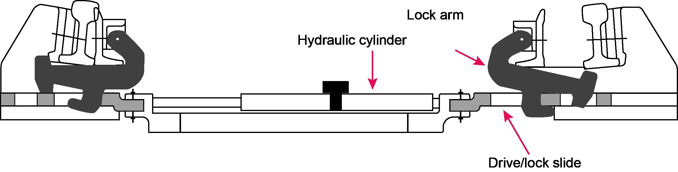
Figure 11: Clamp lock cross section.
6. Power to the motor is switched off by contacts on the circuit controller inside the point machine, (the interlocking also disconnects the power to the points when reverse detection is obtained). 7. The motor is electrically braked by ‘snubbing’ contacts on the circuit controller, (somewhat like regenerative braking), to avoid damage to the motor and mechanical parts when the movement reaches the end of its travel.
Facing point lock tolerances
Although it is desirable from a safety perspective for the gap between the closed switch rail and the stock rail to be as small as possible, (ideally zero), in practice some tolerance must be applied. Without this, the very slightest movement or incorrect adjustment of the points might mean the point lock could not physically engage. If that were to happen, the detection circuits would indicate that the points were not locked, and therefore trains could not be signalled over them. This is a classic example of a points failure, causing delays to trains and requiring a technician to attend the points. The provision of the tolerance is, therefore, a trade-off between safety and reliability. Accordingly, points are adjusted so that with a very small gap between the switch and stock rail, (typically 1.5mm on standard gauge railways), the lock can still engage. If the gap is much larger, (typically 3.5mm), the lock must fail to engage. The normal way of checking these gaps is to use a facing point lock gauge. This is nothing more than a small rectangular piece of metal, 1.5mm thick at one end and 3.5mm thick at the other. Each end is in turn inserted between the stock and switch rails, and the points moved, (generally by hand operation rather than under power), to check that at 1.5 mm the lock engages and that at 3.5mm it does not. The tolerances may vary slightly for different railways and countries, but the principles are the same.
STILL TO COME…
This article has explored the basics of points and point operation, and the role of signalling and the signal engineer in ensuring they work safely. In Part 2 some of the additional features and functions associated with points will be looked at, including topics such as trailable points, catch points, turnouts on high-speed railways, and more.