WO2011099599A1 - Machine tool thermal displacement correction method and thermal displacement correction device - Google Patents
Machine tool thermal displacement correction method and thermal displacement correction device Download PDFInfo
- Publication number
- WO2011099599A1 WO2011099599A1 PCT/JP2011/053019 JP2011053019W WO2011099599A1 WO 2011099599 A1 WO2011099599 A1 WO 2011099599A1 JP 2011053019 W JP2011053019 W JP 2011053019W WO 2011099599 A1 WO2011099599 A1 WO 2011099599A1
- Authority
- WO
- WIPO (PCT)
- Prior art keywords
- thermal
- support
- displacement
- machine tool
- inspection point
- Prior art date
Links
Images


Classifications
-
- B—PERFORMING OPERATIONS; TRANSPORTING
- B23—MACHINE TOOLS; METAL-WORKING NOT OTHERWISE PROVIDED FOR
- B23Q—DETAILS, COMPONENTS, OR ACCESSORIES FOR MACHINE TOOLS, e.g. ARRANGEMENTS FOR COPYING OR CONTROLLING; MACHINE TOOLS IN GENERAL CHARACTERISED BY THE CONSTRUCTION OF PARTICULAR DETAILS OR COMPONENTS; COMBINATIONS OR ASSOCIATIONS OF METAL-WORKING MACHINES, NOT DIRECTED TO A PARTICULAR RESULT
- B23Q15/00—Automatic control or regulation of feed movement, cutting velocity or position of tool or work
- B23Q15/007—Automatic control or regulation of feed movement, cutting velocity or position of tool or work while the tool acts upon the workpiece
- B23Q15/18—Compensation of tool-deflection due to temperature or force
-
- B—PERFORMING OPERATIONS; TRANSPORTING
- B23—MACHINE TOOLS; METAL-WORKING NOT OTHERWISE PROVIDED FOR
- B23Q—DETAILS, COMPONENTS, OR ACCESSORIES FOR MACHINE TOOLS, e.g. ARRANGEMENTS FOR COPYING OR CONTROLLING; MACHINE TOOLS IN GENERAL CHARACTERISED BY THE CONSTRUCTION OF PARTICULAR DETAILS OR COMPONENTS; COMBINATIONS OR ASSOCIATIONS OF METAL-WORKING MACHINES, NOT DIRECTED TO A PARTICULAR RESULT
- B23Q11/00—Accessories fitted to machine tools for keeping tools or parts of the machine in good working condition or for cooling work; Safety devices specially combined with or arranged in, or specially adapted for use in connection with, machine tools
- B23Q11/0003—Arrangements for preventing undesired thermal effects on tools or parts of the machine
- B23Q11/0007—Arrangements for preventing undesired thermal effects on tools or parts of the machine by compensating occurring thermal dilations
-
- G—PHYSICS
- G05—CONTROLLING; REGULATING
- G05B—CONTROL OR REGULATING SYSTEMS IN GENERAL; FUNCTIONAL ELEMENTS OF SUCH SYSTEMS; MONITORING OR TESTING ARRANGEMENTS FOR SUCH SYSTEMS OR ELEMENTS
- G05B19/00—Programme-control systems
- G05B19/02—Programme-control systems electric
- G05B19/18—Numerical control [NC], i.e. automatically operating machines, in particular machine tools, e.g. in a manufacturing environment, so as to execute positioning, movement or co-ordinated operations by means of programme data in numerical form
- G05B19/404—Numerical control [NC], i.e. automatically operating machines, in particular machine tools, e.g. in a manufacturing environment, so as to execute positioning, movement or co-ordinated operations by means of programme data in numerical form characterised by control arrangements for compensation, e.g. for backlash, overshoot, tool offset, tool wear, temperature, machine construction errors, load, inertia
-
- G—PHYSICS
- G05—CONTROLLING; REGULATING
- G05B—CONTROL OR REGULATING SYSTEMS IN GENERAL; FUNCTIONAL ELEMENTS OF SUCH SYSTEMS; MONITORING OR TESTING ARRANGEMENTS FOR SUCH SYSTEMS OR ELEMENTS
- G05B2219/00—Program-control systems
- G05B2219/30—Nc systems
- G05B2219/49—Nc machine tool, till multiple
- G05B2219/49206—Compensation temperature, thermal displacement, use measured temperature
-
- Y—GENERAL TAGGING OF NEW TECHNOLOGICAL DEVELOPMENTS; GENERAL TAGGING OF CROSS-SECTIONAL TECHNOLOGIES SPANNING OVER SEVERAL SECTIONS OF THE IPC; TECHNICAL SUBJECTS COVERED BY FORMER USPC CROSS-REFERENCE ART COLLECTIONS [XRACs] AND DIGESTS
- Y10—TECHNICAL SUBJECTS COVERED BY FORMER USPC
- Y10T—TECHNICAL SUBJECTS COVERED BY FORMER US CLASSIFICATION
- Y10T408/00—Cutting by use of rotating axially moving tool
- Y10T408/16—Cutting by use of rotating axially moving tool with control means energized in response to activator stimulated by condition sensor
Definitions
- the present invention relates to a thermal displacement correction method and a thermal displacement correction device for a machine tool.
- Patent Document 1 discloses a method of correcting the command position of the drive shaft by measuring the column inclination using a distance sensor.
- the conventional thermal displacement correction method it is possible to measure the tilt angle when tilted at a certain tilt angle from the base support portion of the column.
- the column does not incline at a constant inclination angle, so that even if the conventional thermal displacement method is applied, a thermal displacement error may occur.
- This invention is made in view of the said subject, and it aims at providing the thermal displacement correction method and thermal displacement correction apparatus of a machine tool which can correct thermal displacement more accurately.
- a thermal displacement correction method for a machine tool comprising: a support body; and a movable body that is movably supported by the support body and moves relative to the support body based on a command position.
- an inspection point position information acquisition step of acquiring thermal displacement positions of at least three inspection points set on the support;
- An approximate curve calculating step for calculating an approximate curve of the deformed shape of the support after the support is thermally deformed based on the thermal displacement position at each inspection point;
- a correction value calculating step of calculating a correction value for the command position based on the command position of the moving body and the approximate curve;
- the inspection point position information acquisition step includes An inclination for obtaining an inclination change amount of an inclination after thermal displacement of each inspection point after the support is thermally deformed with respect to a reference inclination of each inspection point before the support is thermally deformed. Change amount acquisition process; Each inspection point from the reference position after the support is thermally displaced with respect to a reference length of the support from the reference position of the support to each of the inspection points before the support is thermally deformed.
- the inspection point position information acquisition step includes A post-heat-displacement inclination acquisition step of acquiring the post-heat-displacement inclination of each inspection point after the support is thermally deformed; Each inspection point from the reference position after the support is thermally displaced with respect to a reference length of the support from the reference position of the support to each of the inspection points before the support is thermally deformed.
- one of the inspection points set on the support body is a support point where the support body is supported by the bed of the machine tool. It is to be.
- the structural feature of the invention according to claim 5 is that in claim 2 or 3, One of the inspection points set on the support is a support point where the support is supported by the bed of the machine tool,
- the gradient change amount acquisition step is to acquire the gradient change amount at the support point as a constant value.
- the thermal expansion amount acquisition step is measured by a temperature sensor disposed at each of the inspection points. Obtaining the amount of thermal expansion based on the temperature of the support.
- the thermal expansion amount acquisition step is measured by a strain sensor disposed at each of the inspection points.
- the thermal expansion amount is obtained based on the strain amount of the support.
- the thermal expansion amount acquisition step is measured by a distance sensor disposed on the bed of the machine tool. Acquiring the thermal expansion amount based on the distance to the inspection point.
- the correction value calculating step includes correcting the command position of the drive shaft perpendicular to the moving direction of the moving body. The value is to be calculated.
- the constitutional feature of the invention according to claim 11 is that in claim 10, the correction value calculating step further calculates a correction value for the command position of the drive shaft parallel to the moving direction of the moving body. is there.
- thermo influence of the machine tool is generated by the movement of the movable body. It is a thermal effect on the surface.
- a thermal displacement correction device for a machine tool comprising: a support body; and a moving body that is movably supported by the support body and moves relative to the support body based on a command position.
- inspection point position information acquisition means for acquiring thermal displacement positions of at least three inspection points set on the support; Based on the thermal displacement position at each of the inspection points, approximate curve calculating means for calculating an approximate curve of the deformed shape of the support after the support is thermally displaced; Correction value calculation means for calculating a correction value for the command position based on the command position of the moving body and the approximate curve; Correction means for correcting the command position of the moving body by the correction value; It is to provide.
- the correction value calculated in the correction amount calculating step approximates the deformed shape of the support when it is thermally deformed by a thermal effect with a curve, and commands the moving body corresponding to the approximate curve.
- the configuration is calculated from the position.
- the support that supports the moving body is deformed by thermal expansion due to thermal effects such as machining of the machine tool and changes in environmental temperature.
- At least three inspection points set on the support are displaced with thermal deformation of the support due to thermal influence.
- transformation shape of a support body is calculated
- the inspection point position information acquisition step includes a thermal displacement position calculation step of calculating the thermal displacement position of each inspection point based on the change amount of the inclination and the amount of thermal expansion.
- the gradient change amount acquisition step is measured in the reference inclination measured at the initial state before the support is thermally deformed and in the deformed state after the support is thermally deformed by machining of the machine tool.
- An inclination change amount is calculated from a difference in inclination after thermal displacement at the inspection point.
- the inclination of the inspection point is measured by a sensor such as an inclinometer arranged at the inspection point, for example.
- the gradient change amount acquisition step the gradient change amount is acquired based on the reference gradient and the thermal displacement gradient at each inspection point measured in this way.
- the support that supports the moving body is deformed by thermal expansion due to thermal effects such as machining of the machine tool and changes in environmental temperature.
- the thermally expanded support body is changed in length by the amount of thermal expansion corresponding to the temperature due to the thermal effect and the linear expansion coefficient of the material. Therefore, the thermal expansion amount acquisition step is performed after the thermal displacement from the reference position measured in the initial state of the support to each inspection point and the reference position measured in the deformed state of the support to each inspection point.
- the amount of thermal expansion is calculated from the difference in length.
- the amount of change in inclination and the amount of thermal elongation obtained by calculating in this way are those produced by thermal deformation of the support due to the thermal effect of the machine tool.
- the gradient change amount is approximated to a displacement angle indicating in which direction the inspection point is displaced.
- This displacement angle is, for example, an angle formed by a straight line passing through the inspection point before and after the displacement and the horizontal plane when the inclination is measured as an inclination with respect to the horizontal plane. Then, it is possible to calculate how much the inspection point is displaced in which direction with the thermal deformation of the support from the displacement angle (the change amount of the inclination) and the obtained thermal expansion amount of the inspection point.
- the thermal displacement position of the inspection point can be calculated more easily.
- the inspection point position information acquisition step includes a thermal displacement position calculation step of calculating the thermal displacement position of each inspection point based on the displacement trajectory and the post-thermal displacement gradient.
- the displacement trajectory of the inspection point is an inspection point trajectory that is displaced in accordance with the thermal deformation of the support.
- the support has a thermal expansion amount that varies depending on the linear expansion coefficient of the material. Therefore, the deformation shape in the peripheral part where each inspection point is set can be estimated by the amount of thermal expansion that changes with the temperature of the part.
- the displacement trajectory of the inspection point accompanying the thermal deformation of the peripheral part is stored in advance according to the amount of thermal expansion.
- the inspection point position information acquisition step acquires a displacement trajectory corresponding to the thermal extension amount acquired by the thermal extension amount acquisition step.
- the thermal displacement position calculation step obtains a position on the acquired displacement trajectory with the post-thermal displacement gradient of the acquired inspection point as a tangent, and calculates the contact point as the thermal displacement position of the inspection point. Thereby, the thermal displacement position of the inspection point can be calculated with higher accuracy.
- one of the inspection points set on the support is a support point that is supported by the bed of the machine tool.
- the support is supported so as to be movable or immovable with respect to the bed of the machine tool. That is, when the support is deformed due to the thermal influence of the machine tool, the support is thermally deformed with reference to the support point supported by the bed. Therefore, this support point can be set as an inspection point that is not displaced by the influence of heat. Thereby, an inspection point position information acquisition process can acquire easily the thermal displacement position of the inspection point which is a support point.
- one of the inspection points set on the support is a support point where the support is supported by the bed of the machine tool.
- the post-heat displacement gradient at the support point is obtained as a constant value.
- the thermal elongation amount acquisition step is configured to detect the thermal elongation amount based on the temperature of the support measured by the temperature sensor arranged at the inspection point.
- the support that supports the moving body is deformed by thermal expansion due to thermal effects such as machining of the machine tool and changes in environmental temperature.
- the thermally expanded support body is changed in length by the amount of thermal expansion corresponding to the temperature due to the thermal effect and the linear expansion coefficient of the material.
- the thermal deformation of the support is caused by the thermal expansion of the support due to the thermal effect of the machine tool.
- the thermal expansion amount of the support body accompanying this thermal deformation is a value according to temperature and the linear expansion coefficient of a material.
- the thermal expansion amount acquisition step the expansion characteristics with respect to the temperature of the support such as the linear expansion coefficient are stored in advance.
- the thermal expansion amount of a support body is computable based on the temperature measured by the temperature sensor arrange
- the thermal expansion amount acquisition step is configured to detect the thermal expansion amount based on the strain amount of the support measured by the strain sensor arranged at the inspection point.
- the strain sensor may be, for example, a strain gauge that changes the internal resistance value due to the expansion and contraction of the support and measures the strain amount based on the change in the resistance value.
- a thermal expansion amount acquisition process can measure the distortion amount accompanying the thermal deformation of a support body, and can detect the thermal expansion amount of a support body from this distortion amount.
- the thermal expansion amount acquisition step is configured to detect the thermal expansion amount based on the distance to the inspection point measured by the distance sensor arranged on the bed of the machine tool.
- the support body is thermally deformed with reference to the supported bed. That is, the amount of thermal expansion of the support before and after thermal deformation can be detected by measuring the distance to the inspection point displaced by the distance sensor arranged on the reference bed.
- the inspection points are set to at least four places on the support.
- an approximate curve is calculated based on the thermal displacement positions of at least three inspection points.
- an approximate curve of a quadratic curve can be calculated based on four or more thermal displacement positions.
- the correction value calculating step calculates the correction value of the drive shaft perpendicular to the moving direction of the moving body.
- the support that supports the moving body may be thermally deformed so as to bend the moving direction of the moving body when the support is deformed due to a thermal effect.
- the correction process can correct the command position of the drive shaft with the drive shaft orthogonal to the drive shaft that drives the moving body as a correction target.
- appropriate thermal displacement correction can be performed by reflecting the correction value.
- the correction value calculating step is configured to further calculate a correction value of the drive shaft parallel to the moving direction of the moving body.
- the correction step uses a drive axis parallel to the moving direction of the moving body, that is, a driving axis that drives the moving body, and corrects the command position of the driving axis. be able to.
- appropriate thermal displacement correction can be performed by reflecting the correction value.
- the thermal influence of the machine tool is a thermal influence on the sliding surface of the support that is generated when the movable body moves.
- the support body is thermally expanded and deformed due to thermal effects such as machining of machine tools and changes in environmental temperature.
- the heat generated by the movement of the supporting moving body greatly affects the thermal deformation of the supporting body. Therefore, the thermal effect of the machine tool may be the thermal effect on the sliding surface of the support body on which the moving body moves.
- the deformed shape of the support can be approximated by a curve as this sliding surface. Therefore, it is possible to calculate a correction value for the sliding surface and perform more appropriate thermal displacement correction.
- the correction value calculated by the correction amount calculating means approximates the deformed shape when the support is thermally deformed by the thermal effect with a curve, and instructs the moving body corresponding to the approximate curve.
- the configuration is calculated from the position.
- the support that supports the moving body is deformed by thermal expansion due to thermal effects such as machining of the machine tool and changes in environmental temperature.
- At least three inspection points set on the support are displaced with thermal deformation of the support due to thermal influence.
- transformation shape of a support body is calculated
- thermal displacement correction method for a machine tool according to the present invention can be similarly applied to the thermal displacement correction apparatus for a machine tool according to the present invention.
- the effect in this case also has the same effect as the effect as the thermal displacement correction method for the machine tool.
- FIG. 1 is an overall view of a machine tool 1 according to a first embodiment.
- FIG. 3 is a block diagram showing a thermal displacement correction device 50.
- FIG. 4 is a side view showing a deformed state of the column 10.
- FIG. 6 is an explanatory diagram of calculation of correction values.
- FIG. 5 is a partially enlarged view of FIG. 4. These are block diagrams which show 2nd embodiment: the thermal displacement correction apparatus 150.
- FIG. FIG. 6 is an explanatory diagram of calculation of correction values.
- FIG. 8 is an enlarged view of a part of FIG. 7.
- a thermal displacement correction method and a thermal displacement correction apparatus for a machine tool according to the present invention will be described with reference to the drawings.
- a machine tool a three-axis machining center will be described as an example. That is, the machine tool is a machine tool having three rectilinear axes (X, Y, Z axes) orthogonal to each other as drive axes.
- FIG. 1 is an overall view of the machine tool 1.
- FIG. 2 is a block diagram showing the thermal displacement correction device.
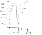
- FIG. 3 is a side view showing a deformed state of the column.
- the machine tool 1 includes a bed 2, a column 10 (corresponding to a “supporting body” of the present invention), a saddle 20 (corresponding to a “moving body” of the present invention), a spindle base body. 30, a table 40, and a numerical controller 50 (corresponding to the “thermal displacement correction device” of the present invention).
- the bed 2 has rails in the Z-axis direction (direction parallel to the floor surface) formed on the upper surface, and is installed on the floor surface.
- the workpiece W is a workpiece to be processed by the machine tool 1.
- the saddle column 10 is a support that is fixed so as to stand on the upper surface of the bed 2 and supports the saddle 20. Since the column 10 is deformed by a thermal effect such as machining of the machine tool 1 or a change in environmental temperature, the thermal displacement correction device is intended to correct the thermal displacement of the saddle 20 accompanying the thermal deformation of the column 10. Therefore, in this embodiment, as shown in FIG. 3, three inspection points Pa1, Pb1, Po are set in the column 10, and a displacement point Pa2 which is a thermal displacement position of each inspection point in accordance with the thermal deformation of the column 10. , Pb2, Po based on thermal displacement correction.
- the first inspection point Pa1 and the second inspection point Pb1 are set near the upper part and the central part of the column 10 in the Y-axis direction (direction perpendicular to the floor surface).
- the reference inspection point Po is set to a support point at which the column 10 is supported by the bed 2 at the lower part of the column 10 in the Y-axis direction. Details of the setting of each inspection point and the thermal displacement correction will be described later.
- the column 10 includes a plurality of inclinometers 11, a plurality of temperature sensors 12, and rails 13 in order to perform thermal displacement correction.
- the inclinometer 11 is installed in two locations corresponding to the inspection points Pa1 and Pb2 set in the column 10 inside the column 10.
- the inclinometer 11 detects the inclination angle of the column 10 at each place where it is installed, and outputs a signal corresponding to the inclination angle to the numerical controller 70 described later.
- the soot temperature sensor 12 is installed in three locations in the column 10, that is, the location where the inclinometer 11 is disposed and the location corresponding to the reference inspection point Po set in the column 10.
- the temperature sensor 12 detects the temperature of the column 10 at each installed location, and outputs a signal corresponding to the temperature to the numerical controller 70.
- the saddle rail 13 is formed on the side surface of the column 10 so as to extend in the Y-axis direction.
- the saddle 20 is a moving body that is provided on the rail 13 of the column 10 and is movable with respect to the column 10 in the Y-axis direction.
- the saddle 20 slides in the Y-axis direction by a rotational drive of a Y-axis motor (not shown) fixed to the column 10.
- the side surface of the column 10 on which the rail 13 in the Y-axis direction is formed is a sliding surface 10a of the column 10 on which the saddle 20 slides.
- the saddle 20 has a guide groove in the X-axis direction (a direction parallel to the floor surface) formed on the side surface.
- the saddle spindle base 30 is a feed base that has a spindle head 31, a rotary spindle 32, and a tool 33, and is movable in the X-axis direction with respect to the saddle 20.
- the spindle head 31 is formed with a rail in the X-axis direction and is slidably fitted in the guide groove of the saddle 20.
- the spindle head 31 moves the entire spindle base 30 in the X-axis direction by rotational driving of an X-axis motor (not shown) fixed to the saddle 20.
- the rod rotation main shaft 32 is rotatably provided by a main shaft motor housed in the housing of the main shaft head 31 and supports the tool 33.
- the tool 33 is fixed to the tip of the rotary main shaft 32 of the main shaft base 30. That is, the tool 33 rotates with the rotation of the rotation spindle 32.
- the tool 33 is, for example, a drill or a tap. That is, the machine tool 1 that is the three-axis machining center can move the tool 33 in the X-axis direction and the Y-axis direction with respect to the bed 2.
- the machine tool 1 can move the workpiece W in the Z-axis direction.
- the heel table 40 is a feed base that is provided on a rail in the Z-axis direction of the bed 2 and is movable in the Z-axis direction with respect to the bed 2.
- the table 40 is moved in the Z-axis direction by a rotational drive of a Z-axis motor (not shown) fixed to the bed 2.
- the table 40 is provided with a jig 41 for fixing the workpiece W at a predetermined position.
- the workpiece W moves in the Z-axis direction with respect to the bed 2 as the table 40 moves in the Z-axis direction.
- the saddle 20, the spindle base 30, and the table 40 are controlled to move to the command position based on the command position by the control device 50.
- the tool 33 is moved relative to the workpiece W for processing.
- the scissors control device 50 controls each shaft motor, main shaft motor, and the like based on the NC data.
- the control device 50 is a thermal displacement correction device that corrects thermal displacement at each part of the column 10 due to the thermal effect of the machine tool 1.
- the structure of the characteristic part of this invention among the control apparatuses 50 of the machine tool 1 is demonstrated.
- the eyelid control device 50 includes a control unit 51, an approximate curve calculation unit 52, a correction value calculation unit 53, a correction unit 54, and an inspection point position information acquisition unit 60.
- the control unit 51, the approximate curve calculation unit 52, the correction value calculation unit 53, the correction unit 54, and the inspection point position information acquisition unit 60 can be configured by individual hardware or realized by software. It can also be set as the structure to do.
- the saddle control unit 51 controls each axis motor, the main shaft motor, and the like based on the input NC data.
- the control device 50 controls the saddle 20, the main spindle base 30, and the table 40 to move, and performs processing by moving the tool 33 that is rotationally driven with respect to the workpiece W relative to the workpiece W.
- the control device 50 is a thermal displacement correction device that corrects thermal displacement due to the thermal effect of the machine tool 1. That is, the control device 50 calculates a correction value corresponding to the deformation of the column 10 due to the thermal effect of the machine tool 1, and corrects the control of each axis motor and the like by the control unit 51 based on this correction value. High accuracy is achieved.
- the “control device 50” is also referred to as a “thermal displacement correction device 50”.
- the inspection point position information acquisition unit 60 of the thermal displacement correction device 50 acquires the displacement points Pa2, Pb2, Po of the inspection points Pa1, Pb1, Po set in the column 10 after the column 10 is thermally deformed. This is position information acquisition means.
- the inspection point position information acquisition unit 60 includes an inclination change amount acquisition unit 61, a thermal expansion amount acquisition unit 62, and a thermal displacement position calculation unit 63.
- the gradient change amount acquisition unit 61 acquires the gradient change amounts of the inspection points Pa1, Pb1, Po set at three positions of the column 10 before and after the column 10 as the support is thermally deformed. It is an acquisition means.
- the inclination of the inspection point Pa1 set near the upper part of the column 10 and the inclination of the inspection point Pb2 set near the central part of the column 10 are respectively measured by inclinometers 11 installed at two places.
- the gradient change amount acquisition unit 61 measures the reference gradient of the inspection points Pa1 and Pb1 before the column 10 is thermally deformed. Further, the gradient change amount acquisition unit 61 measures the gradient after thermal displacement of the inspection points Pa1 and Pb1 after the column 10 is thermally deformed. The gradient change amount acquisition unit 61 then calculates the gradients of the inspection points Pa1 and Pb1 before and after the thermal deformation of the column 10 due to the thermal effect of the machine tool 1 based on the difference between the reference gradient and the gradient after thermal displacement. Get the amount of change.
- the column 10 is thermally deformed based on the reference inspection point Po, that is, the support point supported by the bed 2.
- the reference inspection point Po that is, the support point supported by the bed 2.
- the inclination after thermal displacement at the reference inspection point Po set as the support point can be regarded as being equal to the reference inclination before the column 10 is thermally deformed. Therefore, the gradient change amount acquisition unit 61 acquires the gradient after thermal displacement at the reference inspection point Po set as the support point as a constant value.
- the ignition extension acquisition unit 62 is a thermal extension acquisition unit that detects the thermal extension of the column 10 deformed by the thermal effect of the machine tool 1.
- the amount of thermal expansion is from the reference position after the column 10 is thermally deformed to each inspection point with respect to the reference length of the column 10 from the reference position of the column 10 to each inspection point before the column 10 is thermally deformed. This is the length of the support after thermal displacement.
- the reference position of the column 10 is a support point (reference inspection point Po).
- the column 10 that supports the saddle 20 as a moving body is thermally expanded and deformed by the thermal effect of the machine tool 1.
- the length of the thermally expanded column 10 changes with the amount of thermal expansion corresponding to the temperature and the linear expansion coefficient of the material. That is, the thermal expansion amount of the column 10 due to thermal deformation is a value corresponding to the temperature and the linear expansion coefficient of the material. Therefore, the thermal expansion amount acquisition unit 62 acquires a value calculated based on the temperature measured at the inspection points Pa1, Pb1, Po and the expansion characteristics of the column 10 as the thermal expansion amount.
- the expansion characteristics of the column 10 are characteristics with respect to the temperature of the column 10 such as the linear expansion coefficient stored in advance in the memory of the thermal displacement correction device 50.
- the thermal displacement position calculation unit 63 is a thermal displacement position calculation unit that calculates the thermal displacement position of each inspection point associated with the thermal deformation of the column 10 based on the amount of change in inclination and the amount of thermal expansion at each inspection point.
- the three inspection points Pa1, Pb1, Po set in the column 10 are displaced along with the thermal deformation of the column 10 due to thermal influence. By grasping the thermal displacement position of each inspection point, the deformed shape of the column 10 can be estimated. Therefore, the thermal displacement position calculation unit 63 determines the displacement point Pa2, which is the thermal displacement position of each inspection point, based on the amount of change in inclination and the amount of thermal expansion at each inspection point whose amount is changed by thermal deformation of the column 10. Pb2 and Po are calculated.
- the thermal displacement position calculation unit 63 sets the thermal displacement position of the reference inspection point Po in the thermal deformation of the column 10 as the original reference inspection point Po. That is, the reference inspection point Po and the displacement point Po are at the same position.
- the heel approximate curve calculation unit 52 is an approximate curve calculation unit that calculates an approximate curve of the deformed shape of the column 10 after the column 10 is thermally deformed based on the thermal displacement position at each inspection point.
- the thermal displacement correction device 50 is configured to grasp the deformation shape of the column 10 by approximating it with a curve. As a result, the thermal displacement correction device 50 calculates a more appropriate correction value. Therefore, the approximate curve calculation unit 52 calculates the approximate curve of the column 10 based on the displacement points Pa2, Pb2, Po calculated by the thermal displacement position calculation unit 63.
- the heel correction value calculation unit 53 is a correction value calculation unit that calculates a correction value for the command value of the saddle 20 based on the command position and approximate curve of the saddle 20 that is a moving body.
- the correction value calculation unit 53 calculates a correction value based on the command position of the saddle 20 based on the command value in the control device 50 and the approximate curve calculated by the approximate curve calculation unit 52.
- the command value in the control device 50 is a value output for controlling each axis motor based on the NC data inputted by the control unit 51.
- the eyelid correction unit 54 is a correction unit that corrects the command position of the saddle 20 with the calculated correction value.
- the Y-axis motor of the column 10 is controlled to rotate, and the saddle 20 as a moving body moves to a predetermined command position.
- the correction value calculation unit 53 associates the command position of the saddle 20 with the approximate curve corresponding to the acquired deformed shape of the column 10. Thereby, it can be estimated how much the position of the command position in the column 10 is displaced due to thermal deformation. That is, the correction unit 54 corrects the command position of the control device 50 with the correction value calculated by the correction value calculation unit 53 from the displacement amount of the part.
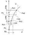
- FIG. 4 is an explanatory diagram for calculating a correction value.
- FIG. 5 is an enlarged view of a part of FIG.
- the thermal displacement correction in the present embodiment is targeted for correction of the thermal displacement of the saddle 20 accompanying the thermal deformation of the column 10 due to thermal influence.
- the thermal displacement correction a correction value of the drive axis (Z axis) perpendicular to the moving direction (Y axis direction) of the saddle 20 as a moving body is calculated.
- the column 10 is deformed by thermal expansion due to thermal effects such as machining of the machine tool 1 and changes in environmental temperature.
- heat generated by the movement of the supporting saddle 20 greatly affects the deformation of the column 10. Therefore, the heat effect of the machine tool 1 is assumed to be the heat effect on the sliding surface 10a of the column 10 on which the saddle 20 moves. Therefore, each inspection point is set on the surface of the sliding surface 10a, and an approximate curve C, which will be described later, is an approximation of the deformation shape of the sliding surface 10a by a curve.
- first inspection point Pa1 a first inspection point
- second inspection point Pb1 a second inspection point
- reference inspection point Po the inspection points are set at equal intervals, and the distance from the uppermost first inspection point Pa1 to the upper end of the column 10 is about half of the distance between the inspection points. It is set. That is, in this embodiment, since there are three inspection points, the first inspection point Pa1 and the second inspection point Pb1 are about 80% to 40% higher than the total height of the column 10 from the bed 2, respectively. Is set. Further, the reference inspection point Po is set to a support point at which the column 10 is supported by the bed 2 as described above.
- each inspection point is displaced along with the thermal deformation as shown in FIG.
- the thermal displacement positions of the first inspection point Pa1 and the second inspection point Pb1 are the first displacement point Pa2 and the second displacement point Pb2, respectively.
- the displacement point Po is at the same position.
- a temperature sensor 12 is installed at each inspection point, and an inclinometer 11 is installed at the first inspection point Pa1 and the second inspection point Pb1. Thereby, the inclination and temperature at each inspection point before and after thermal deformation of the column 10 are measured.
- the thermal displacement position of each inspection point is acquired. Therefore, the gradient change amount of each inspection point is acquired in the gradient change amount acquisition step. That is, the inclination change amount acquisition unit 61 of the inspection point position information acquisition unit 60 inputs the inclination angle of the column 10 at the displacement points Pa2 and Pb2 from the inclinometer 11 as the inclination after thermal displacement. Then, the amount of change in the inclination of each inspection point is calculated from the difference from the reference inclination acquired before the thermal deformation of the column 10.
- the inclination measured at the first inspection point Pa1 is acquired from the memory of the thermal displacement correction device 50.
- the inclination ⁇ measured at the displacement point Pa ⁇ b> 2 is input from the inclinometer 11.
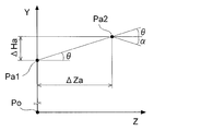
- the gradient change amount ⁇ is calculated as an angle formed with the horizontal line as shown in FIG.
- the gradient change amount acquisition unit 61 always acquires the gradient change amount at the reference inspection point Po as zero.
- the thermal expansion amount acquisition step the thermal expansion amount of the column 10 due to thermal deformation is detected. Therefore, the thermal elongation amount acquisition unit 62 of the inspection point position information acquisition unit 60 inputs the temperatures measured at the displacement points Pa2, Pb2, Po by the temperature sensor 12. Furthermore, the thermal expansion amount acquisition unit 62 acquires the expansion characteristics at each inspection point of the column 10 stored in advance in the memory of the thermal displacement correction device 50. Then, as shown in FIG. 4, the thermal expansion amount acquisition unit 62 detects thermal expansion amounts ⁇ Ha and ⁇ Hb before and after thermal deformation of the column 10 based on the temperature and expansion characteristics at each displacement point.
- the thermal displacement position calculation unit 63 of the inspection point position information acquisition unit 60 calculates the displacement points Pa2, Pb2, Po that are the thermal displacement positions of the respective inspection points based on the change in the slope and the thermal expansion amount.
- the thermal displacement position calculation unit 63 approximates the gradient change amount ⁇ at the first inspection point described above to the displacement angle ⁇ indicating in which direction the first inspection point Pa1 is displaced.
- the displacement angle ⁇ is an angle formed by a straight line passing through the first inspection point Pa1 and the displacement point Pa2 and a horizontal line. Then, based on the displacement angle ⁇ approximated by the inclination change amount ⁇ and the thermal extension amount ⁇ Ha of the first inspection point Pa1, the displacement amount Pa2 in the Z direction of the first inspection point Pa1 is obtained, thereby obtaining the displacement point Pa2. Is calculated. Similarly, the position of the displacement point Pb2, which is the thermal displacement position of the second inspection point Pb1, is calculated.
- the approximate curve calculation unit 52 calculates a quadratic curve that passes through any of the displacement points Pa2, Pb2, and Po, which are the thermal displacement positions of the respective inspection points.
- the approximate curve calculation unit 52 uses the calculated quadratic curve as the approximate curve C in the column 10.
- the correction value calculation unit 53 In the wrinkle correction value calculation step, a correction value for the command value of the saddle 20 is calculated. Therefore, the correction value calculation unit 53 first acquires the command position Py of the saddle 20 based on the command value in the control device 50. Next, the correction value calculation unit 53 associates the command position Py of the saddle 20 with the approximate curve C corresponding to the deformed shape of the column 10 and calculates the correction value Rz. In the correction step, the command position is corrected with this correction value. That is, the correction unit 54 corrects the command position output by the control unit 51 with the calculated correction value Rz.
- the command position for the table 40 is corrected, and the workpiece W is further moved by the correction amount Rz in the Z-axis direction and processed at an appropriate processing position.
- the thermal displacement correction device 50 sequentially corrects the thermal displacement of the saddle 20 accompanying the thermal deformation of the column 10 during machining of the machine tool 1, so that the thermal fluctuation of the column 10 during the machining and the saddle 20 are corrected.
- the processing accuracy is improved.
- the correction value calculated by the correction value calculation unit 53 approximates the deformation shape when the column 10 is thermally deformed by a thermal effect by a curve, and the approximate curve It was calculated from the command position of the saddle 20 corresponding to C. That is, the three inspection points Pa1, Pb1, Po set in the column 10 are displaced with the thermal deformation of the column 10 due to thermal influence. Then, the deformed shape of the column 10 is obtained in a curved line on the basis of the amount of change in inclination and the amount of thermal expansion at each inspection point.
- the correction value corresponding to the command position of the saddle 20 supported by the column 10 can be calculated more accurately than when the deformed shape of the column 10 is obtained linearly. Therefore, various displacement states due to the thermal influence of the machine tool 1 can be dealt with, and thermal displacement correction can be performed with higher accuracy.
- the thermal displacement position calculation unit 63 of the inspection point position information acquisition unit 60 calculates the displacement points Pa2 and Pb2 that are the thermal displacement positions of the respective inspection points based on the inclination change amount and the thermal extension amount. That is, at the first inspection point Pa1, the slope change amount ⁇ is calculated from the difference between the reference slope measured before and after the column 10 is thermally deformed and the slope after thermal displacement. The thermal displacement position calculation unit 63 approximates the change amount ⁇ of the inclination to a displacement angle ⁇ indicating in which direction the inspection point is displaced.
- one of the inspection points set in the column 10 is a support point where the column 10 is supported by the bed 2 of the machine tool 1.
- the column 10 is supported so as not to move relative to the bed 2 of the machine tool 1. That is, when the column 10 is deformed due to the thermal effect of the machine tool 1, the column 10 is thermally deformed based on the support point supported by the bed 2. Therefore, this support point is set as a reference inspection point Po that is not displaced by the influence of heat. Thereby, the measurement of the inclination of the reference inspection point Po, which is the support point, and the detection of the thermal extension amount can be simplified.
- the gradient change amount acquisition unit 61 acquires the gradient after thermal displacement at the reference inspection point Po with the support point as the inspection point as a constant value.
- the column 10 is thermally deformed based on the support point supported by the bed 2 when thermally deforming.
- the post-heat displacement gradient at the reference inspection point Po which is the support point, can be regarded as a constant value (zero) before and after the column 10 is thermally deformed. Therefore, the gradient change amount acquisition unit 61 can omit the measurement of the gradient after thermal displacement at the inspection point.
- the ignition elongation acquisition unit 62 detects the amount of thermal extension based on the temperature of the column 10 measured by the temperature sensor 12 arranged at each inspection point. Further, the thermal deformation of the column 10 results from the thermal expansion of the column 10 due to the thermal effect of the machine tool 1. And the thermal expansion amount of the column 10 accompanying this thermal deformation is a value according to temperature and the linear expansion coefficient of a material. Therefore, the thermal expansion amount acquisition unit 62 acquires a linear expansion coefficient that is an expansion characteristic with respect to the temperature of the column 10 stored in advance in the memory of the thermal displacement correction device 50. Thereby, the thermal expansion amount of the column 10 can be calculated based on the temperature measured by the temperature sensor 12 arranged at the inspection point and the linear expansion coefficient of the column 10.
- the eyelid correction value calculation unit 53 calculates the correction value Rz of the drive axis (Z axis) perpendicular to the moving direction of the saddle 20.
- the column 10 that supports the saddle 20 may be thermally deformed so that the moving direction of the saddle 20 is curved in the Z-axis direction when deformed due to thermal influence. is there.
- the correction unit 54 sets the Z-axis orthogonal to the drive axis (Y-axis) for driving the saddle 20 as a correction target, and the Z-axis The command position can be corrected.
- appropriate thermal displacement correction can be performed by reflecting the correction value Rz.
- the heat effect of the machine tool 1 is assumed to be the heat effect on the sliding surface 10a of the column 10 generated by the movement of the saddle 20.
- the column 10 is deformed by thermal expansion due to thermal effects such as machining of the machine tool 1 and changes in environmental temperature.
- heat generated by the movement of the supporting saddle 20 greatly affects the thermal deformation of the column 10. Therefore, the heat effect of the machine tool 1 is assumed to be the heat effect on the sliding surface 10a of the column 10 on which the saddle 20 moves.
- the deformed shape of the column 10 can be approximated by a curve as the sliding surface 10a. Therefore, the correction value Rz for the sliding surface 10a can be calculated, and more appropriate thermal displacement correction can be performed.
- FIG. 6 is a block diagram showing the thermal displacement correction device 150.
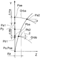
- FIG. 7 is an explanatory diagram for calculating a correction value.
- FIG. 8 is an enlarged view of a part of FIG.
- the second embodiment is different from the first embodiment in the method for calculating the thermal displacement position of each inspection point in the inspection point position information acquisition step of thermal displacement correction. Since other configurations are substantially the same as those of the first embodiment, detailed description thereof is omitted.
- the inspection point position information acquisition unit 160 of the thermal displacement correction device 150 of the present embodiment includes a post-heat-displacement gradient acquisition unit 164, a thermal expansion amount acquisition unit 62, and a thermal displacement position calculation unit 163. And have.
- the post-thermal displacement gradient acquisition unit 164 is a post-thermal displacement gradient acquisition unit that acquires the post-thermal displacement gradient of each inspection point after the column 10 serving as a support is thermally deformed.
- the thermal displacement position calculation unit 163 is a thermal displacement position calculation unit that calculates the thermal displacement position of each inspection point based on the displacement trajectory of each inspection point and the gradient after thermal displacement described later.
- the thermal displacement correction by the scorching thermal displacement correction device 150 first acquires the thermal displacement position of each inspection point in the inspection point position information acquisition step as in the first embodiment. For this reason, in the post-thermal displacement gradient acquisition step, the post-thermal displacement gradient of each inspection point is acquired. That is, the post-heat-displacement inclination acquisition unit 164 of the inspection point position information acquisition unit 160 inputs the inclination angle of the column 10 at the displacement points Pa ⁇ b> 2 and Pb ⁇ b> 2 from the inclinometer 11. In addition, the post-heat-displacement slope acquisition unit 164 always acquires the slope at the reference inspection point Po as zero.
- the thermal expansion amount acquisition unit 62 of the inspection point position information acquisition unit 160 inputs the temperatures measured at the displacement points Pa2, Pb2, Po by the temperature sensor 12. Furthermore, the thermal expansion amount acquisition unit 62 acquires the expansion characteristics at each inspection point of the column 10 stored in advance in the memory of the thermal displacement correction device 50. And the thermal expansion amount acquisition part 62 detects thermal expansion amount (DELTA) Ha and (DELTA) Hb before and behind the thermal deformation of the column 10 based on the temperature and expansion characteristic in each displacement point, as shown in FIG.
- the thermal displacement position calculation unit 163 of the inspection point position information acquisition unit 160 acquires the displacement trajectories of the first inspection point Pa1 and the second inspection point Pb1. Then, the thermal displacement position calculation unit 163 calculates the displacement points Pa2, Pb2, Po, which are the thermal displacement positions of the respective inspection points, based on the post-thermal displacement gradient of each inspection point and the acquired displacement trajectory.
- the inspection point displacement trajectory is a trajectory of each inspection point that accompanies thermal deformation of the column 10 from a state in which the column 10 is not thermally deformed, and is set in advance according to the temperature or the amount of thermal expansion. Is.
- the column 10 has a thermal expansion amount that changes depending on the linear expansion coefficient of the material. Therefore, the deformation shape in the peripheral part where each inspection point is set in the column 10 can be estimated by the amount of thermal expansion that changes with the temperature of the part. Therefore, the memory of the thermal displacement correction device 50 stores in advance the displacement trajectory of the inspection point associated with the thermal deformation of the peripheral portion according to the thermal expansion amount. Then, the thermal displacement position calculation unit 163 acquires displacement trajectories Orba and Orbb corresponding to the thermal expansion amounts ⁇ Ha and ⁇ Hb detected by the thermal expansion amount acquisition unit 62.
- the thermal displacement position calculation unit 163 sets the point Pae where the first inspection point Pa1 has moved by the thermal expansion amount ⁇ Ha as the starting point of the acquired displacement trajectory Orba. And the thermal displacement position calculation part 163 calculates
- the scorching displacement position calculation unit 163 calculates the contact point thus obtained as a displacement point Pa2 that is a heat displacement position of the first inspection point Pa1. Similarly, the position where the second inspection point Pb1 is moved by the thermal expansion amount ⁇ Hb is used as the starting point of the acquired displacement trajectory Orbb, and the position where the inclination of the displacement point Pb2 is tangent is obtained. Thereby, the position of the displacement point Pb2, which is the thermal displacement position of the second inspection point Pb1, is calculated.
- the approximate curve calculation unit 52 calculates a quadratic curve that passes through any of the displacement points Pa2, Pb2, and Po, which are the thermal displacement positions of the respective inspection points.
- the approximate curve calculation unit 52 uses the calculated quadratic curve as the approximate curve C in the column 10. Since the subsequent steps in the thermal displacement correction are substantially the same as those in the first embodiment, description thereof is omitted.
- the thermal displacement position calculation unit 163 calculates the displacement points Pa2 and Pb2 that are the thermal displacement positions of the respective inspection points based on the inclination and the displacement trajectory. Thereby, the thermal displacement position of the inspection point can be calculated with higher accuracy.
- the thermal displacement correction devices 50 and 150 of the machine tool 1 are based on the temperature measured by the temperature sensor 12 arranged at each inspection point in the thermal elongation amount acquisition step. Was to be detected.
- This strain sensor may be, for example, a strain gauge that changes the internal resistance value due to the expansion and contraction of the column 10 and measures the strain amount by the change in the resistance value.
- the amount of strain accompanying thermal deformation of the column 10 can be measured, and the amount of thermal expansion of the column 10 can be detected from the amount of strain.
- a distance sensor may be disposed on the scissors or the bed 2 of the machine tool 1, and the amount of thermal expansion may be detected based on the distance to the inspection point measured by the distance sensor.
- the thermal expansion amount acquisition step may detect the thermal expansion amount by various means instead of the temperature sensor 12. In this case, the same effect as that of the first embodiment can be obtained.
- the inspection points are set at three places in the column 10.
- the approximate curve calculation step required at least three inspection points in order to approximate the deformed shape with a curve because the column 10 is thermally deformed in a curve.
- this approximate curve calculation step for example, when the approximate curve C is calculated by a least square method or the like, an approximate curve of a quadratic curve can be calculated based on four or more thermal displacement positions. . Thereby, the approximate curve C approximated by the deformed shape of the column 10 can be calculated. Therefore, since an appropriate correction value Rz can be calculated, the thermal displacement correction can be performed with higher accuracy.
- the correction value calculation step may be configured to further calculate a correction value of the drive axis (Y axis) parallel to the moving direction of the saddle 20.
- Y axis the drive axis
- the Y-axis correction value Ry is further calculated based on the thermal expansion amounts ⁇ Ha and ⁇ Hb of each inspection point, thereby correcting the Y-axis command position, which is the moving direction of the saddle 20. Can do.
- more appropriate thermal displacement correction can be performed by appropriately reflecting the correction value Ry with respect to the movement direction of the saddle 20.
- the thermal effect of the machine tool 1 is the thermal effect on the sliding surface 10a of the column 10 generated by the movement of the saddle 20.
- the thermal influence of the machine tool 1 may be caused by rotation of each axis motor or spindle motor due to processing of the machine tool 1, change in environmental temperature, heat generation at each sliding surface, and the like. Therefore, when the column 10 is thermally deformed due to these thermal effects, a reference position approximated by a curve in the column 10 may be set as appropriate. Therefore, more appropriate thermal displacement correction can be performed in response to various thermal effects.
- the thermal displacement correction has been described as being due to thermal deformation of the column 10 as a support.
- the thermal displacement correction method of the present invention can be applied to any member that supports the tool 33 or the workpiece W and causes thermal displacement due to the thermal effect of the machine tool 1.
- the machine tool 1 has been described by taking a three-axis machining center as an example.
- the machine tool 1 may be, for example, a 5-axis machining center having a rotation axis (A, B axis). Even in such a configuration, the same effect can be obtained.
Abstract
Description
上記の課題を解決するため、請求項1に記載の工作機械の熱変位補正方法に係る発明の構成上の特徴は、
支持体と、当該支持体に移動可能に支持され指令位置に基づいて前記支持体に対して移動する移動体と、を備える工作機械の熱変位補正方法において、
前記支持体が熱変形した後において、前記支持体に設定された少なくとも3箇所の各検査点の熱変位位置を取得する検査点位置情報取得工程と、
各前記検査点における前記熱変位位置に基づいて、前記支持体が熱変形した後における前記支持体の変形形状の近似曲線を算出する近似曲線算出工程と、
前記移動体の前記指令位置と前記近似曲線とに基づいて前記指令位置に対する補正値を算出する補正値算出工程と、
前記補正値により前記移動体の前記指令位置を補正する補正工程と、
を備えることである。 (Machine tool thermal displacement compensation method)
In order to solve the above problems, the structural features of the invention relating to the thermal displacement correction method for a machine tool according to
In a thermal displacement correction method for a machine tool comprising: a support body; and a movable body that is movably supported by the support body and moves relative to the support body based on a command position.
After the support is thermally deformed, an inspection point position information acquisition step of acquiring thermal displacement positions of at least three inspection points set on the support;
An approximate curve calculating step for calculating an approximate curve of the deformed shape of the support after the support is thermally deformed based on the thermal displacement position at each inspection point;
A correction value calculating step of calculating a correction value for the command position based on the command position of the moving body and the approximate curve;
A correction step of correcting the command position of the moving body by the correction value;
It is to provide.
前記検査点位置情報取得工程は、
前記支持体が熱変形する前における各前記検査点の基準斜度に対して、前記支持体が熱変形した後における各前記検査点の熱変位後斜度の斜度変化量を取得する斜度変化量取得工程と、
前記支持体の基準位置から前記支持体が熱変形する前における各前記検査点までの前記支持体の基準長さに対して、前記支持体が熱変位した後における前記基準位置から各前記検査点までの前記支持体の熱変位後長さの熱伸長量を取得する熱伸長量取得工程と、
各前記検査点における前記斜度変化量および前記熱伸長量に基づいて、各前記検査点の前記熱変位位置を算出する熱変位位置算出工程と、
を有することである。 The structural feature of the invention described in
The inspection point position information acquisition step includes
An inclination for obtaining an inclination change amount of an inclination after thermal displacement of each inspection point after the support is thermally deformed with respect to a reference inclination of each inspection point before the support is thermally deformed. Change amount acquisition process;
Each inspection point from the reference position after the support is thermally displaced with respect to a reference length of the support from the reference position of the support to each of the inspection points before the support is thermally deformed. A thermal extension amount acquisition step of acquiring a thermal extension amount of a length after thermal displacement of the support until
A thermal displacement position calculating step of calculating the thermal displacement position of each inspection point based on the slope change amount and the thermal extension amount at each inspection point;
It is to have.
前記検査点位置情報取得工程は、
前記支持体が熱変形した後における各前記検査点の熱変位後斜度を取得する熱変位後斜度取得工程と、
前記支持体の基準位置から前記支持体が熱変形する前における各前記検査点までの前記支持体の基準長さに対して、前記支持体が熱変位した後における前記基準位置から各前記検査点までの前記支持体の熱変位後長さの熱伸長量を取得する熱伸長量取得工程と、
前記支持体が熱変形していない状態から前記支持体が熱変形することに伴う各前記検査点の変位軌道を予め設定し、当該変位軌道と取得した前記斜度変化量とに基づいて、各前記検査点の前記熱変位位置を算出する熱変位位置算出工程と、
を有することである The structural feature of the invention described in claim 3 is that in
The inspection point position information acquisition step includes
A post-heat-displacement inclination acquisition step of acquiring the post-heat-displacement inclination of each inspection point after the support is thermally deformed;
Each inspection point from the reference position after the support is thermally displaced with respect to a reference length of the support from the reference position of the support to each of the inspection points before the support is thermally deformed. A thermal extension amount acquisition step of acquiring a thermal extension amount of a length after thermal displacement of the support until
Preset a displacement trajectory of each inspection point associated with thermal deformation of the support from a state in which the support is not thermally deformed, and based on the displacement trajectory and the acquired amount of change in inclination, A thermal displacement position calculating step of calculating the thermal displacement position of the inspection point;
Is to have
前記支持体に設定された前記検査点のうち1箇所は、前記支持体が前記工作機械のベッドに支持された支持点であり、
前記斜度変化量取得工程は、前記支持点における前記斜度変化量を一定値として取得することである。 The structural feature of the invention according to claim 5 is that in
One of the inspection points set on the support is a support point where the support is supported by the bed of the machine tool,
The gradient change amount acquisition step is to acquire the gradient change amount at the support point as a constant value.
請求項10に記載の発明の構成上の特徴は、請求項1~9の何れか一項において、前記補正値算出工程は、前記移動体の移動方向に垂直な駆動軸の前記指令位置に対する補正値を算出することである。
請求項11に記載の発明の構成上の特徴は、請求項10において、前記補正値算出工程は、前記移動体の移動方向に平行な駆動軸の前記指令位置に対する補正値をさらに算出することである。 The structural feature of the invention described in claim 9 is that, in any one of
According to a tenth aspect of the present invention, in any one of the first to ninth aspects, the correction value calculating step includes correcting the command position of the drive shaft perpendicular to the moving direction of the moving body. The value is to be calculated.
The constitutional feature of the invention according to
上記の課題を解決するため、請求項13に記載の工作機械の熱変位補正装置に係る発明の構成上の特徴は、
支持体と、当該支持体に移動可能に支持され指令位置に基づいて前記支持体に対して移動する移動体と、を備える工作機械の熱変位補正装置において、
前記支持体が熱変形した後において、前記支持体に設定された少なくとも3箇所の各検査点の熱変位位置を取得する検査点位置情報取得手段と、
各前記検査点における前記熱変位位置に基づいて、前記支持体が熱変位した後における前記支持体の変形形状の近似曲線を算出する近似曲線算出手段と、
前記移動体の前記指令位置と前記近似曲線とに基づいて前記指令位置に対する補正値を算出する補正値算出手段と、
前記補正値により前記移動体の前記指令位置を補正する補正手段と、
を備えることである。 (Machine tool thermal displacement compensation device)
In order to solve the above-described problem, the structural features of the invention relating to the thermal displacement correction device for a machine tool according to
In a thermal displacement correction device for a machine tool, comprising: a support body; and a moving body that is movably supported by the support body and moves relative to the support body based on a command position.
After the support is thermally deformed, inspection point position information acquisition means for acquiring thermal displacement positions of at least three inspection points set on the support;
Based on the thermal displacement position at each of the inspection points, approximate curve calculating means for calculating an approximate curve of the deformed shape of the support after the support is thermally displaced;
Correction value calculation means for calculating a correction value for the command position based on the command position of the moving body and the approximate curve;
Correction means for correcting the command position of the moving body by the correction value;
It is to provide.
第一実施形態の工作機械1の熱変位補正装置について図1~図3を参照して説明する。図1は、工作機械1の全体図である。図2は、熱変位補正装置を示すブロック図である。図3は、コラムの変形状態を示す側面図である。 <First embodiment>
A thermal displacement correction device for a
工作機械1は、図1に示すように、ベッド2と、コラム10(本発明の「支持体」に相当する)と、サドル20(本発明の「移動体」に相当する)と、主軸基体30と、テーブル40と、数値制御装置50(本発明の「熱変位補正装置」に相当する)とを備える。ベッド2は、上面にZ軸方向(床面に平行な方向)のレールが形成され、床面に設置されている。工作物Wは、工作機械1によって加工される被加工部材である。 (Configuration of machine tool 1)
As shown in FIG. 1, the
以下、工作機械1の熱変位補正について、図3~図5を参照して説明する。図4は、補正値の算出の説明図である。図5は、図4の一部の拡大図である。また、本実施形態における熱変位補正は、熱影響によるコラム10の熱変形に伴うサドル20の熱変位を補正の対象としている。そして、説明を簡易化するために、コラム10は、図3に示すように、熱影響によりZ軸方向に反り返るように熱変形するものとする。換言すると、熱影響によるコラム10の変形のうち、Y-Z平面に投影される変形形状に係る熱変位を補正対象としている。よって、熱変位補正は、移動体であるサドル20の移動方向(Y軸方向)に垂直な駆動軸(Z軸)の補正値を算出するものとする。 (Thermal displacement correction)
Hereinafter, the thermal displacement correction of the
上述した工作機械1の熱変位補正装置50によれば、補正値算出部53において算出される補正値は、熱影響によりコラム10が熱変形した際の変形形状を曲線で近似し、その近似曲線Cに対応するサドル20の指令位置から算出するものとした。つまり、コラム10に設定されている3箇所の検査点Pa1,Pb1,Poは、熱影響によるコラム10の熱変形に伴い変位することになる。そして、各検査点の斜度変化量および熱伸長量に基づいてコラム10の変形形状を曲線的に求めている。これにより、コラム10の変形形状を直線的に求めた場合と比較して、コラム10に支持されるサドル20の指令位置に対応した補正値をより正確に算出することができる。よって、工作機械1の熱影響による多様な変位状態に対応し、より高精度に熱変位補正が可能となる。 (Effect of thermal displacement compensation device)
According to the thermal
第二実施形態の工作機械1の熱変位補正装置について図6~図8を参照して説明する。図6は、熱変位補正装置150を示すブロック図である。図7は、補正値の算出の説明図である。図8は、図7の一部の拡大図である。ここで、第二実施形態は、熱変位補正の検査点位置情報取得工程において、各検査点の熱変位位置の算出方法が第一実施形態と相違する。その他の構成については、第一実施形態と実質的に同一であるため、詳細な説明を省略する。 <Second embodiment>
A thermal displacement correction apparatus for the
第一、第二実施形態において、工作機械1の熱変位補正装置50,150は、熱伸長量取得工程において、各検査点に配置された温度センサ12により測定される温度に基づいて熱伸長量を検出するものとした。これに対して、検査点に歪みセンサを配置し、この歪みセンサにより測定される歪み量に基づいて熱伸長量を検出する構成としてもよい。この歪みセンサは、例えば、コラム10の伸縮により内部の抵抗値が変化し、この抵抗値の変化により歪み量を測定する歪みゲージとしてもよい。そして、熱伸長量取得工程は、コラム10の熱変形に伴う歪み量を測定し、この歪み量からコラム10の熱伸長量を検出することができる。 <Modification of the first and second embodiments>
In the first and second embodiments, the thermal
Claims (13)
- 支持体と、当該支持体に移動可能に支持され指令位置に基づいて前記支持体に対して移動する移動体と、を備える工作機械の熱変位補正方法において、
前記支持体が熱変形した後において、前記支持体に設定された少なくとも3箇所の各検査点の熱変位位置を取得する検査点位置情報取得工程と、
各前記検査点における前記熱変位位置に基づいて、前記支持体が熱変形した後における前記支持体の変形形状の近似曲線を算出する近似曲線算出工程と、
前記移動体の前記指令位置と前記近似曲線とに基づいて前記指令位置に対する補正値を算出する補正値算出工程と、
前記補正値により前記移動体の前記指令位置を補正する補正工程と、
を備えることを特徴とする工作機械の熱変位補正方法。 In a thermal displacement correction method for a machine tool comprising: a support body; and a movable body that is movably supported by the support body and moves relative to the support body based on a command position.
After the support is thermally deformed, an inspection point position information acquisition step of acquiring thermal displacement positions of at least three inspection points set on the support;
An approximate curve calculating step for calculating an approximate curve of the deformed shape of the support after the support is thermally deformed based on the thermal displacement position at each inspection point;
A correction value calculating step of calculating a correction value for the command position based on the command position of the moving body and the approximate curve;
A correction step of correcting the command position of the moving body by the correction value;
A method for correcting thermal displacement of a machine tool, comprising: - 請求項1において、
前記検査点位置情報取得工程は、
前記支持体が熱変形する前における各前記検査点の基準斜度に対して、前記支持体が熱変形した後における各前記検査点の熱変位後斜度の斜度変化量を取得する斜度変化量取得工程と、
前記支持体の基準位置から前記支持体が熱変形する前における各前記検査点までの前記支持体の基準長さに対して、前記支持体が熱変位した後における前記基準位置から各前記検査点までの前記支持体の熱変位後長さの熱伸長量を取得する熱伸長量取得工程と、
各前記検査点における前記斜度変化量および前記熱伸長量に基づいて、各前記検査点の前記熱変位位置を算出する熱変位位置算出工程と、
を有することを特徴とする工作機械の熱変位補正方法。 In claim 1,
The inspection point position information acquisition step includes
An inclination for obtaining an inclination change amount of an inclination after thermal displacement of each inspection point after the support is thermally deformed with respect to a reference inclination of each inspection point before the support is thermally deformed. Change amount acquisition process;
Each inspection point from the reference position after the support is thermally displaced with respect to a reference length of the support from the reference position of the support to each of the inspection points before the support is thermally deformed. A thermal extension amount acquisition step of acquiring a thermal extension amount of a length after thermal displacement of the support until
A thermal displacement position calculating step of calculating the thermal displacement position of each inspection point based on the slope change amount and the thermal extension amount at each inspection point;
A method for correcting thermal displacement of a machine tool, comprising: - 請求項1において、
前記検査点位置情報取得工程は、
前記支持体が熱変形した後における各前記検査点の熱変位後斜度を取得する熱変位後斜度取得工程と、
前記支持体の基準位置から前記支持体が熱変形する前における各前記検査点までの前記支持体の基準長さに対して、前記支持体が熱変位した後における前記基準位置から各前記検査点までの前記支持体の熱変位後長さの熱伸長量を取得する熱伸長量取得工程と、
前記支持体が熱変形していない状態から前記支持体が熱変形することに伴う各前記検査点の変位軌道を予め設定し、当該変位軌道と取得した前記熱変位後斜度とに基づいて、各前記検査点の前記熱変位位置を算出する熱変位位置算出工程と、
を有することを特徴とする工作機械の熱変位補正方法。 In claim 1,
The inspection point position information acquisition step includes
A post-heat-displacement inclination acquisition step of acquiring the post-heat-displacement inclination of each inspection point after the support is thermally deformed;
Each inspection point from the reference position after the support is thermally displaced with respect to a reference length of the support from the reference position of the support to each of the inspection points before the support is thermally deformed. A thermal extension amount acquisition step of acquiring a thermal extension amount of a length after thermal displacement of the support until
Preset the displacement trajectory of each of the inspection points accompanying the thermal deformation of the support from a state in which the support is not thermally deformed, based on the displacement trajectory and the acquired post-thermal displacement gradient, A thermal displacement position calculating step of calculating the thermal displacement position of each inspection point;
A method for correcting thermal displacement of a machine tool, comprising: - 請求項1において、
前記支持体に設定された前記検査点のうち1箇所は、前記支持体が前記工作機械のベッドに支持された支持点であることを特徴とする工作機械の熱変位補正方法。 In claim 1,
One of the inspection points set on the support is a support point where the support is supported by a bed of the machine tool. - 請求項2または3において、
前記支持体に設定された前記検査点のうち1箇所は、前記支持体が前記工作機械のベッドに支持された支持点であり、
前記支持点における前記熱変位後斜度は、一定値として取得されることを特徴とする工作機械の熱変位補正方法。 In claim 2 or 3,
One of the inspection points set on the support is a support point where the support is supported by the bed of the machine tool,
A thermal displacement correction method for a machine tool, wherein the post-heat displacement gradient at the support point is acquired as a constant value. - 請求項2,3,5の何れか一項において、
前記熱伸長量取得工程は、各前記検査点に配置された温度センサにより測定される前記支持体の温度に基づいて前記熱伸長量を取得することを特徴とする工作機械の熱変位補正方法。 In any one of Claims 2, 3, and 5,
The thermal expansion correction method for a machine tool, wherein the thermal expansion amount acquisition step acquires the thermal expansion amount based on a temperature of the support measured by a temperature sensor arranged at each inspection point. - 請求項2,3,5の何れか一項において、
前記熱伸長量取得工程は、各前記検査点に配置された歪みセンサにより測定される前記支持体の歪み量に基づいて前記熱伸長量を取得することを特徴とする工作機械の熱変位補正方法。 In any one of Claims 2, 3, and 5,
The thermal expansion correction method for a machine tool, wherein the thermal expansion amount acquisition step acquires the thermal expansion amount based on a strain amount of the support measured by a strain sensor arranged at each inspection point. . - 請求項2,3,5の何れか一項において、
前記熱伸長量取得工程は、前記工作機械のベッドに配置された距離センサにより測定される前記検査点までの距離に基づいて前記熱伸長量を取得することを特徴とする工作機械の熱変位補正方法。 In any one of Claims 2, 3, and 5,
The thermal extension correction step of the machine tool, wherein the thermal extension amount acquisition step acquires the thermal extension amount based on a distance to the inspection point measured by a distance sensor arranged on the bed of the machine tool. Method. - 請求項1~8の何れか一項において、
前記検査点は、前記支持体に少なくとも4箇所以上に設定されていることを特徴とする工作機械の熱変位補正方法。 In any one of claims 1 to 8,
The method for correcting a thermal displacement of a machine tool, wherein the inspection points are set in at least four or more locations on the support. - 請求項1~9の何れか一項において、
前記補正値算出工程は、前記移動体の移動方向に垂直な駆動軸の前記指令位置に対する補正値を算出することを特徴とする工作機械の熱変位補正方法。 In any one of claims 1 to 9,
The method of correcting a thermal displacement of a machine tool, wherein the correction value calculating step calculates a correction value for the command position of the drive shaft perpendicular to the moving direction of the moving body. - 請求項10において、
前記補正値算出工程は、前記移動体の移動方向に平行な駆動軸の前記指令位置に対する補正値をさらに算出することを特徴とする工作機械の熱変位補正方法。 In claim 10,
The method of correcting a thermal displacement of a machine tool, wherein the correction value calculating step further calculates a correction value for the command position of the drive shaft parallel to the moving direction of the movable body. - 請求項1~11の何れか一項において、
前記工作機械の熱影響は、前記移動体が移動することにより発生する前記支持体の摺動面における熱影響であることを特徴とする工作機械の熱変位補正方法。 In any one of claims 1 to 11,
A thermal displacement correction method for a machine tool, wherein the thermal effect of the machine tool is a thermal effect on a sliding surface of the support that is generated when the movable body moves. - 支持体と、当該支持体に移動可能に支持され指令位置に基づいて前記支持体に対して移動する移動体と、を備える工作機械の熱変位補正装置において、
前記支持体が熱変形した後において、前記支持体に設定された少なくとも3箇所の各検査点の熱変位位置を取得する検査点位置情報取得手段と、
各前記検査点における前記熱変位位置に基づいて、前記支持体が熱変位した後における前記支持体の変形形状の近似曲線を算出する近似曲線算出手段と、
前記移動体の前記指令位置と前記近似曲線とに基づいて前記指令位置に対する補正値を算出する補正値算出手段と、
前記補正値により前記移動体の前記指令位置を補正する補正手段と、
を備えることを特徴とする工作機械の熱変位補正装置。 In a thermal displacement correction device for a machine tool, comprising: a support body; and a moving body that is movably supported by the support body and moves relative to the support body based on a command position.
After the support is thermally deformed, inspection point position information acquisition means for acquiring thermal displacement positions of at least three inspection points set on the support;
Based on the thermal displacement position at each of the inspection points, approximate curve calculating means for calculating an approximate curve of the deformed shape of the support after the support is thermally displaced;
Correction value calculation means for calculating a correction value for the command position based on the command position of the moving body and the approximate curve;
Correction means for correcting the command position of the moving body by the correction value;
A thermal displacement correction apparatus for machine tools, comprising:
Priority Applications (3)
| Application Number | Priority Date | Filing Date | Title |
|---|---|---|---|
| EP11742342A EP2537631A1 (en) | 2010-02-15 | 2011-02-14 | Machine tool thermal displacement correction method and thermal displacement correction device |
| CN201180009396.0A CN102753302B (en) | 2010-02-15 | 2011-02-14 | The thermal displacement correction method of lathe and thermal displacement correction device |
| US13/579,142 US20130028673A1 (en) | 2010-02-15 | 2011-02-14 | Thermal displacement correction method and thermal displacement correction device for machine tool |
Applications Claiming Priority (2)
| Application Number | Priority Date | Filing Date | Title |
|---|---|---|---|
| JP2010-030037 | 2010-02-15 | ||
| JP2010030037A JP5418272B2 (en) | 2010-02-15 | 2010-02-15 | Thermal displacement correction method and thermal displacement correction apparatus for machine tool |
Publications (1)
| Publication Number | Publication Date |
|---|---|
| WO2011099599A1 true WO2011099599A1 (en) | 2011-08-18 |
Family
ID=44367866
Family Applications (1)
| Application Number | Title | Priority Date | Filing Date |
|---|---|---|---|
| PCT/JP2011/053019 WO2011099599A1 (en) | 2010-02-15 | 2011-02-14 | Machine tool thermal displacement correction method and thermal displacement correction device |
Country Status (5)
| Country | Link |
|---|---|
| US (1) | US20130028673A1 (en) |
| EP (1) | EP2537631A1 (en) |
| JP (1) | JP5418272B2 (en) |
| CN (1) | CN102753302B (en) |
| WO (1) | WO2011099599A1 (en) |
Cited By (2)
| Publication number | Priority date | Publication date | Assignee | Title |
|---|---|---|---|---|
| US9671500B1 (en) * | 2015-12-22 | 2017-06-06 | GM Global Technology Operations LLC | Systems and methods for locating a vehicle |
| IT202100018767A1 (en) * | 2021-07-15 | 2023-01-15 | Scm Group Spa | Workpiece processing machine incorporating a detection system and corresponding method of operation. |
Families Citing this family (14)
| Publication number | Priority date | Publication date | Assignee | Title |
|---|---|---|---|---|
| JP5811102B2 (en) * | 2011-05-17 | 2015-11-11 | 株式会社ジェイテクト | Thermal displacement correction apparatus and thermal displacement correction method |
| JP5956497B2 (en) * | 2014-04-08 | 2016-07-27 | ファナック株式会社 | Machine thermal displacement compensation device |
| USD788196S1 (en) * | 2014-09-12 | 2017-05-30 | Pocket NC Company | Multi-axis machine |
| KR20170058334A (en) * | 2015-03-17 | 2017-05-26 | 도시바 기카이 가부시키가이샤 | Machine tool |
| CN105415092A (en) * | 2016-01-07 | 2016-03-23 | 宁波天瑞精工机械有限公司 | Temperature compensation method for motorized spindle of numerical control machine tool |
| CN105759719B (en) * | 2016-04-20 | 2018-08-24 | 合肥工业大学 | A kind of numerical control machining tool heat error prediction technique and system splitting model based on unbiased esti-mator |
| KR101801897B1 (en) * | 2016-06-23 | 2017-12-20 | 한국항공우주산업 주식회사 | Process management system and method for quality control of aviation parts industry |
| JP6802208B2 (en) * | 2018-03-23 | 2020-12-16 | ファナック株式会社 | Thermal displacement correction system and calculator |
| USD861750S1 (en) * | 2018-05-02 | 2019-10-01 | Pocket NC Company | Multi-axis machine |
| IT201800007230A1 (en) * | 2018-07-16 | 2020-01-16 | NUMERICAL CONTROL MACHINE TOOL | |
| EP3839414A1 (en) * | 2019-12-20 | 2021-06-23 | Hexagon Technology Center GmbH | Advanced thermal compensation of mechanical processes |
| CN112631202A (en) * | 2020-12-25 | 2021-04-09 | 津上精密机床(浙江)有限公司 | Machining temperature correction method, system, device and computer storage medium |
| TWI752782B (en) * | 2020-12-31 | 2022-01-11 | 和昕精密科技有限公司 | System and method for assembly and shaft position correction of general-purpose transmission core of processing machine |
| CN114594726A (en) * | 2022-02-17 | 2022-06-07 | 成都飞机工业(集团)有限责任公司 | Method for detecting thermal elongation of spindle of numerical control machine tool and electronic equipment |
Citations (12)
| Publication number | Priority date | Publication date | Assignee | Title |
|---|---|---|---|---|
| JPS61226246A (en) * | 1985-03-28 | 1986-10-08 | Toshiba Mach Co Ltd | Machine tool with heat displacement preventer |
| JPS62213945A (en) * | 1986-03-12 | 1987-09-19 | Toshiba Mach Co Ltd | Thermal displacement correcting device for machine tool |
| JPH01166052U (en) * | 1988-05-16 | 1989-11-21 | ||
| JPH048452A (en) * | 1990-04-24 | 1992-01-13 | Okuma Mach Works Ltd | Smoothing method of thermal displacement compensation value |
| JPH04135141A (en) * | 1990-09-26 | 1992-05-08 | Yotaro Hatamura | Work machine |
| JPH068107A (en) * | 1992-06-29 | 1994-01-18 | Hitachi Seiko Ltd | Thermal displacement compensation method for machine tool |
| JPH06170694A (en) * | 1991-05-27 | 1994-06-21 | Yotaro Hatamura | Work machine |
| JPH06190687A (en) * | 1992-12-24 | 1994-07-12 | Mitsubishi Heavy Ind Ltd | Thermal displacement correcting device for machine tool |
| JP2001054839A (en) * | 1999-08-20 | 2001-02-27 | Okuma Corp | Thermal displacement reducing device for machine |
| JP2006272539A (en) * | 2005-03-30 | 2006-10-12 | Brother Ind Ltd | Machine tool and displacement correction method of machine tool |
| JP2006281420A (en) * | 2005-04-05 | 2006-10-19 | Okuma Corp | Heat displacement compensating method of nc machine tool |
| JP2009184077A (en) * | 2008-02-07 | 2009-08-20 | Mitsubishi Heavy Ind Ltd | Machine tool |
Family Cites Families (2)
| Publication number | Priority date | Publication date | Assignee | Title |
|---|---|---|---|---|
| DE60136555D1 (en) * | 2000-10-16 | 2008-12-24 | Makino Milling Machine | MEASURING METHOD AND DEVICE, WITH SUCH A PROCESSING METHOD |
| CN101412080B (en) * | 2008-08-10 | 2010-12-15 | 燕山大学 | Novel sheet bar funnel-type crystallizer and method for producing the same |
-
2010
- 2010-02-15 JP JP2010030037A patent/JP5418272B2/en not_active Expired - Fee Related
-
2011
- 2011-02-14 WO PCT/JP2011/053019 patent/WO2011099599A1/en active Application Filing
- 2011-02-14 EP EP11742342A patent/EP2537631A1/en not_active Withdrawn
- 2011-02-14 CN CN201180009396.0A patent/CN102753302B/en not_active Expired - Fee Related
- 2011-02-14 US US13/579,142 patent/US20130028673A1/en not_active Abandoned
Patent Citations (12)
| Publication number | Priority date | Publication date | Assignee | Title |
|---|---|---|---|---|
| JPS61226246A (en) * | 1985-03-28 | 1986-10-08 | Toshiba Mach Co Ltd | Machine tool with heat displacement preventer |
| JPS62213945A (en) * | 1986-03-12 | 1987-09-19 | Toshiba Mach Co Ltd | Thermal displacement correcting device for machine tool |
| JPH01166052U (en) * | 1988-05-16 | 1989-11-21 | ||
| JPH048452A (en) * | 1990-04-24 | 1992-01-13 | Okuma Mach Works Ltd | Smoothing method of thermal displacement compensation value |
| JPH04135141A (en) * | 1990-09-26 | 1992-05-08 | Yotaro Hatamura | Work machine |
| JPH06170694A (en) * | 1991-05-27 | 1994-06-21 | Yotaro Hatamura | Work machine |
| JPH068107A (en) * | 1992-06-29 | 1994-01-18 | Hitachi Seiko Ltd | Thermal displacement compensation method for machine tool |
| JPH06190687A (en) * | 1992-12-24 | 1994-07-12 | Mitsubishi Heavy Ind Ltd | Thermal displacement correcting device for machine tool |
| JP2001054839A (en) * | 1999-08-20 | 2001-02-27 | Okuma Corp | Thermal displacement reducing device for machine |
| JP2006272539A (en) * | 2005-03-30 | 2006-10-12 | Brother Ind Ltd | Machine tool and displacement correction method of machine tool |
| JP2006281420A (en) * | 2005-04-05 | 2006-10-19 | Okuma Corp | Heat displacement compensating method of nc machine tool |
| JP2009184077A (en) * | 2008-02-07 | 2009-08-20 | Mitsubishi Heavy Ind Ltd | Machine tool |
Cited By (4)
| Publication number | Priority date | Publication date | Assignee | Title |
|---|---|---|---|---|
| US9671500B1 (en) * | 2015-12-22 | 2017-06-06 | GM Global Technology Operations LLC | Systems and methods for locating a vehicle |
| US20170176599A1 (en) * | 2015-12-22 | 2017-06-22 | General Motors Llc | Systems and methods for locating a vehicle |
| IT202100018767A1 (en) * | 2021-07-15 | 2023-01-15 | Scm Group Spa | Workpiece processing machine incorporating a detection system and corresponding method of operation. |
| EP4119291A1 (en) * | 2021-07-15 | 2023-01-18 | SCM Group S.p.A. | Machine for processing workpieces comprising a detection system and corresponding operation method |
Also Published As
| Publication number | Publication date |
|---|---|
| JP2011161614A (en) | 2011-08-25 |
| US20130028673A1 (en) | 2013-01-31 |
| CN102753302B (en) | 2015-08-19 |
| EP2537631A1 (en) | 2012-12-26 |
| JP5418272B2 (en) | 2014-02-19 |
| CN102753302A (en) | 2012-10-24 |
Similar Documents
| Publication | Publication Date | Title |
|---|---|---|
| JP5418272B2 (en) | Thermal displacement correction method and thermal displacement correction apparatus for machine tool | |
| JP5632036B2 (en) | Device for correcting errors in CNC machine tools | |
| JP5113086B2 (en) | Method and apparatus for correcting displacement of machine tool | |
| JP5816475B2 (en) | Industrial machinery | |
| JP2014191607A (en) | Numerical control machine tool, and correction method of main shaft error in numerical control machine tool | |
| WO2012053353A1 (en) | System for correcting thermal displacement of machine tool | |
| JP7390117B2 (en) | Position measurement method and position measurement system for machine tool objects | |
| JP2005061834A (en) | Error calculation method for working machine having rotary shaft | |
| JP5355037B2 (en) | Accuracy measuring method, error control method for numerically controlled machine tool, and numerically controlled machine tool having error correcting function | |
| TW201124230A (en) | Mechanical displacement compensation system of machine tool. | |
| JP6542629B2 (en) | Positioning device and method for machining tool | |
| US11298781B2 (en) | Workpiece rotating appartus and robot system | |
| US8924176B2 (en) | Industrial machine | |
| US7847502B2 (en) | Device and method for controlling machine tool | |
| JP4172614B2 (en) | Ball screw feed drive correction method | |
| JP2010284737A (en) | Positioning device | |
| KR102060288B1 (en) | Machine tool | |
| JP4626499B2 (en) | Parallel mechanism and calibration method thereof | |
| JP2008246620A (en) | Machine tool, control program for correcting thermal expansion, and storage medium | |
| JP2012011509A (en) | Thermal displacement correcting method and thermal displacement correcting device of machine tool | |
| JP2015009352A (en) | Thermal displacement correction method and thermal displacement correction device | |
| JP2006116654A (en) | Thermal deformation correction method and thermal deformation correcting device of nc machine tool | |
| JP5945995B2 (en) | Positioning device | |
| JP4877012B2 (en) | Machine tool, thermal expansion correction control program, and storage medium | |
| JP2013255978A (en) | Thermal displacement compensation device |
Legal Events
| Date | Code | Title | Description |
|---|---|---|---|
| WWE | Wipo information: entry into national phase |
Ref document number: 201180009396.0 Country of ref document: CN |
|
| 121 | Ep: the epo has been informed by wipo that ep was designated in this application |
Ref document number: 11742342 Country of ref document: EP Kind code of ref document: A1 |
|
| REEP | Request for entry into the european phase |
Ref document number: 2011742342 Country of ref document: EP |
|
| WWE | Wipo information: entry into national phase |
Ref document number: 2011742342 Country of ref document: EP |
|
| WWE | Wipo information: entry into national phase |
Ref document number: 13579142 Country of ref document: US |
|
| NENP | Non-entry into the national phase |
Ref country code: DE |