WO2007114716A1 - Methods for determining proximity between radio frequency devices and controlling switches - Google Patents

Methods for determining proximity between radio frequency devices and controlling switches Download PDF

Info

Publication number
WO2007114716A1
WO2007114716A1 PCT/NZ2007/000069 NZ2007000069W WO2007114716A1 WO 2007114716 A1 WO2007114716 A1 WO 2007114716A1 NZ 2007000069 W NZ2007000069 W NZ 2007000069W WO 2007114716 A1 WO2007114716 A1 WO 2007114716A1
Authority
WO
WIPO (PCT)
Prior art keywords
radio frequency
bluetooth
devices
frequency device
proximity
Prior art date
Application number
PCT/NZ2007/000069
Other languages
French (fr)
Inventor
Nicholas Hedley Willis
Original Assignee
Resonance Holdings Limited
Priority date (The priority date is an assumption and is not a legal conclusion. Google has not performed a legal analysis and makes no representation as to the accuracy of the date listed.)
Filing date
Publication date
Application filed by Resonance Holdings Limited filed Critical Resonance Holdings Limited
Priority to US12/295,670 priority Critical patent/US8792826B2/en
Priority to AU2007232562A priority patent/AU2007232562B2/en
Priority to NZ571374A priority patent/NZ571374A/en
Priority to EP07747697.6A priority patent/EP2002671A4/en
Publication of WO2007114716A1 publication Critical patent/WO2007114716A1/en

Links

Classifications

    • GPHYSICS
    • G01MEASURING; TESTING
    • G01SRADIO DIRECTION-FINDING; RADIO NAVIGATION; DETERMINING DISTANCE OR VELOCITY BY USE OF RADIO WAVES; LOCATING OR PRESENCE-DETECTING BY USE OF THE REFLECTION OR RERADIATION OF RADIO WAVES; ANALOGOUS ARRANGEMENTS USING OTHER WAVES
    • G01S5/00Position-fixing by co-ordinating two or more direction or position line determinations; Position-fixing by co-ordinating two or more distance determinations
    • G01S5/02Position-fixing by co-ordinating two or more direction or position line determinations; Position-fixing by co-ordinating two or more distance determinations using radio waves
    • G01S5/0205Details
    • G01S5/0226Transmitters
    • GPHYSICS
    • G01MEASURING; TESTING
    • G01SRADIO DIRECTION-FINDING; RADIO NAVIGATION; DETERMINING DISTANCE OR VELOCITY BY USE OF RADIO WAVES; LOCATING OR PRESENCE-DETECTING BY USE OF THE REFLECTION OR RERADIATION OF RADIO WAVES; ANALOGOUS ARRANGEMENTS USING OTHER WAVES
    • G01S11/00Systems for determining distance or velocity not using reflection or reradiation
    • G01S11/02Systems for determining distance or velocity not using reflection or reradiation using radio waves
    • G01S11/06Systems for determining distance or velocity not using reflection or reradiation using radio waves using intensity measurements
    • HELECTRICITY
    • H04ELECTRIC COMMUNICATION TECHNIQUE
    • H04WWIRELESS COMMUNICATION NETWORKS
    • H04W12/00Security arrangements; Authentication; Protecting privacy or anonymity
    • H04W12/08Access security

Definitions

  • the invention relates to a method of determining the proximity of a first radio frequency device to a second radio frequency device.
  • the invention further relates to a method for the control of a switch based on the proximity to each other of a first radio frequency device and a second radio frequency device.
  • RSSI is a measure of the signal strength between transmitting and receiving devices.
  • RSSI is a measure of the strength (not necessarily the quality) of the received signal in a radio frequency environment.
  • RSSI is measured in arbitrary units. RSSI can be used internally in a radio frequency networking card to determine when the signal is below a certain threshold. This allows determination of the type of messages to send as well as the timing for those messages.
  • a radio frequency network monitoring tool can be used to measure the signal strength of a wireless network. From this a RSSI value can be determined. An end-user can determine an RSSI value when measuring the signal strength of a wireless network on a radio frequency network monitoring tool.
  • RSSI values are used in a range of situations including the transmission of signals over wires and in various radio frequency technologies including the General Packet Radio Service (GPRS), Global System for Mobile Communications (GSM), Code division multiple access (CDMA), BluetoothTM, ZigBeeTM, Wifi 802. Hx, and other Radio Frequency Identification (RFID) methods.
  • GPRS General Packet Radio Service
  • GSM Global System for Mobile Communications
  • CDMA Code division multiple access
  • BluetoothTM BluetoothTM
  • ZigBeeTM ZigBeeTM
  • Wifi 802. Hx Wireless Fidelity
  • RFID Radio Frequency Identification
  • RSSI is intended to be used in a relative manner. Absolute accuracy of the RSSI reading is not specified.
  • the RSSI is a useful guide to the strength of the signal whether measured in Watts (W) or Decibels (dB).
  • Signal strength (ss) and RSSI can be used as a guide to the distance between transmitting and receiving radio frequency devices.
  • RSSI is used in different ways depending on what the primary objective is.
  • the relative distance of the transmitting and receiving devices is not important. Only the strength and quality of the signal is important in this case.
  • the strength of the signal is not important. However, the relative physical locations of the objects will be important.
  • switches In order to more fully exploit the use of radio frequency devices in the provision of location based services or security applications a need exists to determine the distance between such devices or relative change of distance between such devices, given the presence of these fluctuations.
  • the provision of location based services or security applications requires the operation of switches.
  • Various means and mechanisms for remotely controlling switches are known.
  • the remote control of switches can be used to allow or restrict access to buildings or premises.
  • remote control devices are well known for locking and unlocking cars, garages and the like.
  • remote control devices can be used in combination with electronic devices such as alarm systems, lights, televisions, stereos and DVD players.
  • Remote controls typically require some kind of action on the part of a user to operate them.
  • the user may be required to put a key within a lock.
  • BluetoothTM in the system described in WO 01/63425 has limitations as many Bluetooth devices are not permanently discoverable. Action is required on the part of the user to change the status of the device to make it discoverable.
  • the invention provides a method for determining the proximity to each other of radio frequency devices including the steps of:
  • the analysing the series of results includes determining the change in proximity to each other of the radio frequency devices.
  • the at least one technical indicator is selected from the group consisting of: an exponential moving average; a moving average convergence/divergence.
  • the at least one technical indicator is a combination of an exponential moving average and a moving average convergence/divergence.
  • the two or more radio frequency devices operate in the 2.4 GHz radio bands
  • the radio frequency devices support a radio frequency communication method selected from the group consisting of: General Packet Radio Service; GSM; CMDA; BluetoothTM; ZigBeeTM; Wifi; 802. Hx.
  • GSM General Packet Radio Service
  • CMDA complementary metal-oxide-semiconductor
  • BluetoothTM Wireless Fidelity
  • ZigBeeTM Wireless Fidelity
  • Wifi 802. Hx.
  • the radio frequency devices support the BluetoothTM radio frequency communication method.
  • the transmitting and receiving radio frequency devices communicate in accordance with the BluetoothTM specification.
  • the periodically measuring the RSSI value of a transmitting radio frequency device occurs in the absence of a profile dependent connection being formed between the radio frequency devices.
  • the transmitting radio frequency device is authenticated by BluetoothTM pairing with the receiving radio frequency device but is undiscoverable during the periodically measuring the RSSI value.
  • the invention provides a configuration of radio frequency devices including:
  • a receiving radio frequency device capable of functioning to periodically measure the RSSI value of the transmitting radio frequency device to provide a series of results.
  • the receiving radio frequency device is programmed to analyse the results using at least one technical indicator to determine the proximity of the transmitting and receiving devices.
  • the analysing the results includes determining the change in proximity to each other of the radio frequency devices.
  • the at least one technical indicator is selected from the group consisting of: an exponential moving average; a moving average convergence/divergence.
  • the at least one technical indicator is a combination of an exponential moving average and a moving average convergence/divergence.
  • the radio frequency devices are capable of operating in the 2.4 GHz radio bands
  • the transmitting and receiving radio frequency devices are capable of communicating in accordance with the BluetoothTM specification.
  • the periodically measuring the RSSI value of a transmitting radio frequency device is capable of occurring in the absence of a profile dependent connection being formed between the two or more radio frequency devices.
  • the transmitting radio frequency device is capable of being authenticated by BluetoothTM pairing with the receiving radio frequency device but is undiscoverable during the periodically measuring the RSSI value.
  • the receiving device is capable of providing personal area networking connection to serve HTML pages to administer the configuration.
  • the invention provides a receiving radio frequency device capable of functioning to periodically measure the RSSI value of a transmitting radio frequency device to provide a series of results and programmed to analyse the results using at least one technical indicator to determine the proximity of the transmitting and receiving radio frequency devices.
  • the at least one technical indicator is selected from the group consisting of: an exponential moving average; a moving average convergence/divergence.
  • the at least one technical indicator is a combination of an exponential moving average and a moving average convergence/divergence.
  • the receiving device operates in the 2.4 GHz radio bands.
  • the receiving radio frequency device supports a radio frequency communication method selected from the group consisting of: General Packet Radio Service; GSM; CMDA; BluetoothTM; ZigBeeTM; Wifi; 802.1 Ix.
  • GSM General Packet Radio Service
  • CMDA complementary metal-oxide-semiconductor
  • BluetoothTM Wireless Fidelity
  • ZigBeeTM Wireless Fidelity
  • Wifi 802.1 Ix.
  • the receiving radio frequency device supports the BluetoothTM radio frequency communication method.
  • the receiving radio frequency device communicates in accordance with the BluetoothTM specification.
  • the receiving radio frequency device provides personal area networking connection to serve HTML pages.
  • the invention provides a chip set solution for use in the manufacture of a radio frequency device providing functionality to periodically measure the RSSI value of a transmitting radio frequency device to provide a series of results and analyse the results using at least one technical indicator to determine the proximity of the transmitting radio frequency device.
  • the analysing the results includes determining the change in proximity of the transmitting radio frequency devices.
  • the at least one technical indicator is selected from the group consisting of: an exponential moving average; a moving average convergence/divergence.
  • the at least one technical indicator is a combination of an exponential moving average and a moving average convergence/divergence.
  • the chip set solution is for use in the manufacture of a radio frequency device operating in the 2.4 GHz radio bands.
  • the chip set solution is for use in the manufacture of a radio frequency device supporting a radio frequency communication method selected from the group consisting of: General Packet Radio Service; GSM; CMDA; BluetoothTM; ZigBee M ; Wifi; 802.1 Ix.
  • a radio frequency communication method selected from the group consisting of: General Packet Radio Service; GSM; CMDA; BluetoothTM; ZigBee M ; Wifi; 802.1 Ix.
  • the chip set solution is for use in the manufacture of a radio frequency device supporting the BluetoothTM radio frequency communication method.
  • the invention provides a method of operating a switch including the step of determining the proximity to each other of radio frequency devices.
  • the determining the proximity includes the steps of:
  • a receiving radio frequency device periodically measuring the RSSI value of a transmitting radio frequency device to provide a series of results
  • the analysing the series of results includes determining the change in proximity to each other of the radio frequency devices.
  • the at least one technical indicator is selected from the group consisting of: an exponential moving average; a moving average convergence/divergence.
  • the at least one technical indicator is a combination of an exponential moving average and a moving average convergence/divergence.
  • the periodically measuring the RSSI value of a transmitting radio frequency device occurs in the absence of a profile dependent connection being formed between the radio frequency devices.
  • the transmitting radio frequency device is authenticated (by BluetoothTM pairing) with the receiving radio frequency device but is undiscoverable during the periodically measuring the RSSI value.
  • the receiving radio frequency device is administered by use of the exchange of Business Cards (OBEX profile).
  • OEBX profile the exchange of Business Cards
  • the receiving radio frequency device provides a personal area networking connection to serve HTML pages to administer the system.
  • a signal from at least one of the radio frequency devices is generated in response to the change in proximity of the two or more radio frequency devices.
  • authenticating identification information is obtained in response to a signal from at least one of the radio frequency devices.
  • the authenticated identification information is shared with another system, application or process.
  • the switch is actuated in response to a signal from at least one of the radio frequency devices.
  • the signal from at least one of the radio frequency devices is generated when a predetermined proximity-threshold is reached.
  • the proximity-threshold can be determined by the user of the method depending on the specific requirements.
  • the proximity-thresholds are dynamically tuned based on the occurrence of false positive incidents.
  • the radio frequency devices are paired BluetoothTM devices.
  • the two or more radio frequency devices operate in the 2.4 GHz radio bands
  • the radio frequency devices support a radio frequency communication method selected from the group consisting of: General Packet Radio Service; GSM; CMDA; BluetoothTM; ZigBeeTM; Wifi; 802.1 Ix.
  • the radio frequency devices support the BluetoothTM radio frequency communication method.
  • the transmitting and receiving radio frequency devices communicate in accordance with the BluetoothTM specification.
  • devices include mobile telephones, laptops or other devices including a transmitting and receiving processor.
  • the switch governs the opening or closing of a door selected from the group consisting of: a garage door; a car door; or a security door.
  • the switch may be operable to perform, directly or indirectly, various operations, including without limitation, an electrical or software switch turning a device or product on or off, opening or closing a door, releasing a catch, locking or unlocking a door or window or the like.
  • the switch may be used in association with existing automatic door openers such as those which are commonly used in, for example, cars, garages, cat and dog doors and at entrances to commercial or domestic premises.
  • the switch may be used to trigger another software application for application to other location based services such as mapping a device location, asset tracking, routing, proximity based messaging, including guides, advertising, ticketing, security and safety.
  • location based services such as mapping a device location, asset tracking, routing, proximity based messaging, including guides, advertising, ticketing, security and safety.
  • Authentication means the initiation by the switch controller of the remote device and involves the BluetoothTM paging process.
  • BluetoothTM means the industrial specification for wireless personal area networks that provides a mechanism for exchanging information between cell phones, pocket PCs, PDAs and the like. The protocol centres around short range radio frequency.
  • Discoverable device means a device that responds to inquiry requests. Many devices are only temporarily discoverable and so can not be passively identified through inquiry. "Pairing” means when two BluetoothTM capable devices establish a trusted relationship through the standard Bluetooth mechanism.
  • Periodically measuring means repeatedly measuring a parameter at a predetermined interval of time.
  • Profile dependent connection means a connection that . is formed between two Bluetooth devices using one of the profiles (such as Serial Port or Headset) defined in the Bluetooth specification which occurs above the RFCOMM layer in the Bluetooth communication stack in Figure 6.
  • Radio frequency device means a device capable of transmitting or receiving electro- magnetic waves at specified radio frequencies. Suitable devices may include mobile telephones/cellphones, cell towers, car and portable radios, GPS receivers, RFID readers and transmitters, laptops or other devices including a transmitting and/or receiving processor.
  • Switch means a device which directly or indirectly changes a device from one state to another.
  • a switch may change the state of a lock from locked to unlocked, or of an electronic device from on to off, or trigger an action in a program.
  • “Technical indicator” means the mathematical measures that are traditionally used in financial market analysis to study the historical prices over time of any type of traded security (stocks, commodities, etc.) to attempt to predict future prices. Here we show how these same indicators can be used with RSSI values to predict proximity in wireless systems.
  • Undiscoverable device means a device that is not discoverable as defined by the BluetoothTM specifications (but may still communicate with devices with which it has previously communicated.)
  • Figure 1 Graph presenting signal strength (raw data) versus time.
  • Figure 3 Graph presenting resetting exponential average of signal strength versus time.
  • Figure 4 Graph presenting MACD (26, 12, 9) of signal strength versus time.
  • Figure 5 Graph presenting EMA (12) and MACD (26, 12, 9) of signal strength versus time.
  • FIG. 6 Schematic representation of the architecture of the existing radio frequency technology BluetoothTM.
  • FIG. 7 Schematic representation of switch control utilising the radio frequency technology BluetoothTM proximity reader of the invention.
  • FIG. 8 Schematic representation of access control system utilising the radio frequency technology BluetoothTM proximity reader of the invention.
  • Figure 9 Representation of the process flow for an implementation of the method in a BluetoothTM environment.
  • Figure 10 Representation of the process of getting the next device for measurement.
  • RSSI values to determine the proximity and movement of radio frequency devices relative to one another. Analysis of the RSSI values over time can be used to determine whether the distance between the devices in increasing or decreasing, i.e. whether one of the devices is moving toward or away from the other device.
  • proximity is not only related to signal strength, but also the changes in signal strength over time or the signal strength velocity and acceleration. The variations over time can be used to determine direction of movement which when combined with distance provides a more accurate indicator of proximity.
  • One advantage of the invention is that it allows the relative proximity and movement of two or more radio frequency devices to be determined.
  • the use of the technical indicators, and particularly the exponential moving average and the moving average convergence divergence, allows the underlying trends in movement to be accurately and rapidly determined with a high degree of sensitivity without being affected by false indications caused by environmental fluctuations.
  • the signal strength can be influenced by the physical surrounding.
  • An object moving through the line of sight between the transmitting and receiving devices can have an impact on signal strength. Even a change in the signal reflection from surrounding objects can affect it.
  • the challenge is to identify the underlying trends that relate to distance rather than these environmental fluctuations. This can be achieved through the use of technical indicators.
  • radio frequency devices specifically to use the invention.
  • manufacture of radio frequency devices consisting or either (as opposed to both) a transmitting or receiving device is contemplated.
  • the challenge is to analyse the fluctuating data and thereby to identify trends and make predictions.
  • By applying the analysis tools of financial technical analysis it is possible to identify the trends of signal strength and in doing so measure proximity of the devices.
  • Leading indicators are designed to lead fluctuations. Most represent a form of momentum (or sustained velocity) over a fixed look-back period. The fixed look- back period is the number of periods used to calculate the indicator. Some of the more popular leading indicators include Commodity Channel Index (CCI), Momentum, Relative Strength Index (RSI), Stochastic Oscillator and Williams %R.
  • CCI Commodity Channel Index
  • RSI Relative Strength Index
  • Stochastic Oscillator and Williams %R.
  • momentum oscillators Many leading indicators come in the form of momentum oscillators.
  • Momentum measures the rate-of-change of the fluctuating value. As the value rises, the momentum increases. The faster the values rise (the greater the period-over-period change), the larger the increase in momentum. Once this rise begins to slow, momentum will also slow. As the growth in value reduces, momentum starts to actually decline from previous high levels.
  • trend-following indicators As their name implies, lagging indicators follow the fluctuations and are commonly referred to as trend-following indicators. Rarely, if ever, will these indicators lead the fluctuation. Trend-following indicators work best when values develop strong trends. They are designed to identify a trend and maintain it as long as the trend is intact. Some popular trend-following indicators include moving averages (exponential, simple, weighted, variable) and moving average convergence/divergence [MACD).
  • the aim is to provide a proximity detection of the phone coming within 2 meters of the vehicle in any manner and from any direction.
  • the signal is affected by the different objects in the line of sight between the transmitter and receiver and financial technical analysis techniques where used to identify the underlying trends to remove these fluctuations.
  • the relative signal strength has a maximum of 1000 and a minimum detectable strength of approximately 740. This range has been used to achieve three significant figures of accuracy while using integers.
  • the solid line represents the indicator under consideration
  • dash-dot represents the upper trigger point
  • dash-dot-dot represents the lower trigger point
  • dashed line represents the proximity detection.
  • the scale for proximity detection is positive is within proximity, negative is out of proximity and zero is within the hystersis of the Schmitt Trigger.
  • Moving Average (n) Sum(Previous n values)/n
  • EMA Exponential Moving Average
  • exponential moving averages also called exponentially weighted moving averages or EMAs.
  • EMAs reduce the lag by applying more weight to recent values relative to older values.
  • the weighting applied to the most recent value depends on the specified period of the EMA. The shorter the EMA period, the more weight that will be applied to the most recent value. As such, EMAs will react quicker to recent changes than a simple moving average.
  • the calculation formula is as follows.
  • EMA(current) ( (Price(current) - EMA(prev) ) x Multiplier(N) ) + EMA(prev)
  • EMAs also have the advantage that they can be calculated from one current and one history value reading. Unlike the simple moving average there is no need to store N previous values.
  • EMAs are cumulative and include a contribution (at ever decreasing weighting) of all the historical values. A discontinuity in the values disrupts averaging. For this reason, we have a used a resetting EMA where the average is returned to the raw value if the signal strength reading is lost, hi location based terms, this equates to losing the position of the transmitting device, and making no assumptions on its current movement from it's last known position.
  • the most popular formula for the "standard" MACD is the difference between a 26- period and 12 period exponential moving averages. These values can be altered to come up with a MACD that is better suited for faster or slower signal strengths. Using shorter moving averages will produce a quicker, more responsive indicator, while using longer moving averages will produce a slower indicator, less prone to whipsaws. For our purposes in this discussion 12/26 MACD will be used for explanations.
  • the 12-day EMA is the faster and the 26-day EMA is the slower.
  • MACD(ij) EMA(J) - EMA(i)
  • a 9-day EMA of MACD is plotted along side to act as a trigger line. This creates an acceleration rather than velocity measure (see below).
  • the goal is to identify the . changes of increasing and decreasing signals.
  • proximity measure the goal is to include the velocity of transmitting device. If the transmitting device has a velocity towards the receiving device, the signal strength will be increasing, the fast 12 period EMA will respond quicker than the slower 26 period EMA and MACD will be positive. Conversely a negative MACD indicates the transmitting device is moving away.
  • the relative movement of the objects can be used to create a proximity trigger. If the transmitting device is near (but not in range) and it is moving towards the receiver then it can be considered to have already moved into the required proximity. In mathematical terms this becomes: if the MACD is positive and fast resetting EMA is close to the upper Schmitt Trigger then the device is within range. In this case we used a MACD trigger value of +1 (moving slightly towards) and just out of range EMA(12) signal of 840. The out of proximity range used the smoothed EMA(9) of MACD value of -30 (definitely moving away) and just in range EMA(12) value of 880. There are two key points on this graph ( Figure 4) that demonstrate the early detection of a object moving into range.
  • the first is at 118 seconds and the second at 233 seconds. This corresponds to the values of 119 and 251 from using EMA indicator alone. However the situation of moving slowly into range at 293 seconds was not detected.
  • MACD is a measure of velocity and in this case the velocity was not high enough to create a positive MACD.
  • This particular embodiment relates to the signal strength of Bluetooth receiver inside a car and external Bluetooth transmitting device.
  • the parameters used in this example equate to a proximity range of 2 meters range outside the car.
  • a reduced signal quality can be an indicator of an obstruction which can reduce the measured signal strength while the distance is unchanged.
  • RSSI and Signal Quality By measuring both RSSI and Signal Quality, a more accurate representation of proximity can be achieved by increasing the measured signal strength in proportion to the reduced signal quality.
  • the period at which the EMA are calculated can be adjusted to the volatility of the signal strength received. The lower the number of periods and the more sensitive the detection will be. The challenge is to avoid the false positives.
  • Level of trigger thresholds are dependent on the proximity required and the relative values of RSSI obtained.
  • the size of the buffer zone will also affect the sensitivity of detection. These all have to be tuned for the specific implementation.
  • This indicator is similar to MACD but requires a history of values to be maintained and can not handle discontinuities of lost signals and is therefore not as useful as MACD.
  • the Stochastic Oscillator is a momentum indicator that shows the location of the current close relative to the high/low range over a set number of periods. Closing levels that are consistently near the top of the range indicate accumulation (buying pressure) and those near the bottom of the range indicate distribution (selling pressure).
  • %K 100* (Recent Close - Lowest Close over n periods) / (Highest High over n periods - Lowest Low over n periods)
  • %K is greater than a threshold such 80% the latest value of the signal strength is close to the maximum including the signal strength is close to its maximum over recent times and if nearby this can indicate proximity.
  • This indicator is similar to ROC and MACD but requires a history of values to be maintained and is therefore not as useful as MACD.
  • Williams %R is a momentum indicator that works much like the Stochastic Oscillator.
  • %R 100*(Highest over n periods - Recent close)/ (Highest High over n periods - Lowest Low over n periods)
  • CCI Commodity Channel Index
  • CCI Commodity Channel Index
  • Calculate the Mean Deviation First, calculate the absolute value of the difference between the last period's SMATS and the typical strength price for each of the past n periods. Add all of these absolute values together and divide by n to find the Mean Deviation.
  • the final step is to apply the Typical Strength (TS), the Simple Moving
  • Acceleration measure or a change in velocity can be calculated by the difference between the current velocity and the (exponential) moving average of the velocity. This can be applied to MACD, Stochastic Oscillators and Williams %R. Using acceleration indicators introduces leading characteristics into these lagging momentum indicators. This can be used to further improve the sensitivity of the indicators described above and therefore increasing accuracy.
  • the increased sensitivity can be managed by requiring multiple confirmations from multiple indicators.
  • Figure 6 displays standard BluetoothTM architecture. This can be divided into two main levels as shown in Figure 6 by the dotted lines.
  • the present invention utilises the core BluetoothTM functionality. In this way compatibility issues can be avoided.
  • the BluetoothTM remote device is paired with the BluetoothTM processor in the switch controller. In this way, a trusted relationship is formed with the devices.
  • the BluetoothTM switch controller will initiate an authentication with the remote BluetoothTM device. In the traditional BluetoothTM context this authentication request represents a prelude to establishing a full connection between two or more BluetoothTM devices.
  • BluetoothTM range indicators such as RSSI values and Link Quality can be obtained during the pairing process and can be used to refine the range.
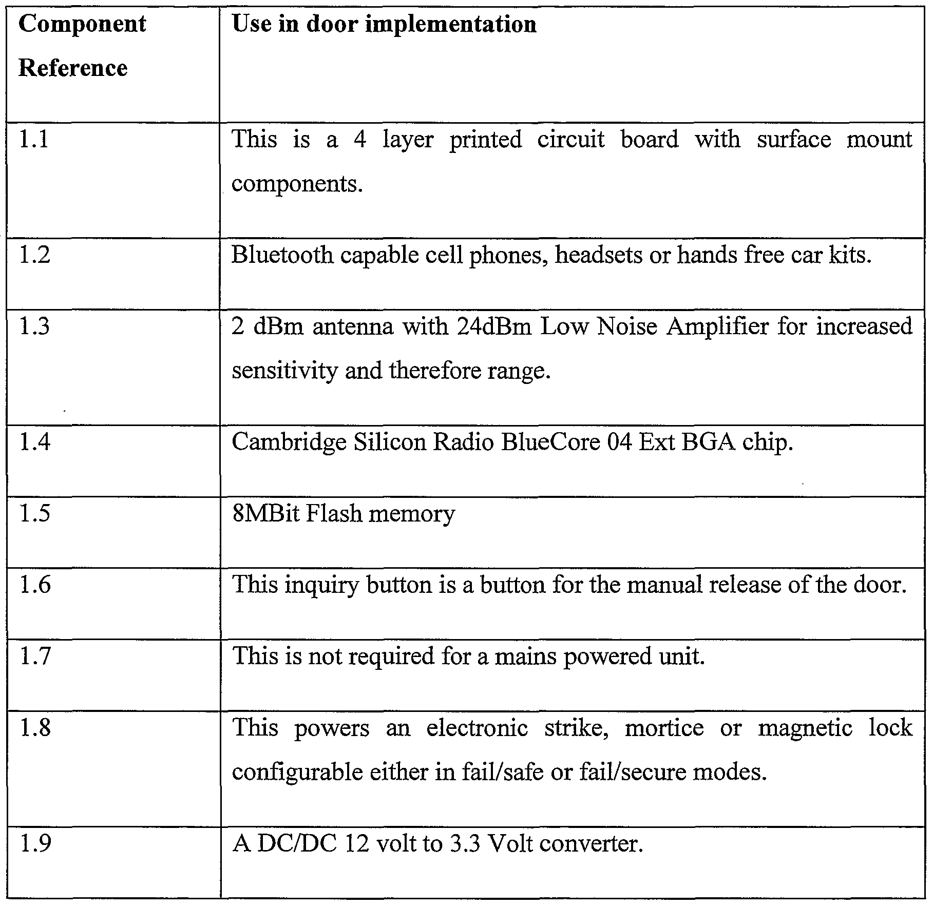
  • FIG 7 describes the switch controller set up in the a preferred embodiment of a single lock configuration.
  • the switch controller (1.1) includes an antenna (1.3) together with a BluetoothTM processor (1.4).
  • the antenna may require an external low noise amplifier for increased sensitivity.
  • the controller additionally includes some persistent memory (1.5).
  • the controller (1.1) is connected to a switch mechanism (1.8) and a power supply (1.9).
  • the switch controller (1.1) sends regular authentication requests to its known trusted devices stored in persistent memory (1.5).
  • a BluetoothTM remote device (1.2) comes into range of the antenna (1.3) it responds to the authentication request and validates its location and authenticity. This occurs whether the remote device is discoverable or not.
  • the receipt of this request is processed by the processor (1.4) and the switch mechanism is triggered.
  • the switch controller may also include an inquiry button (1.6) and an awake sensor (1.7).
  • the inquiry button is used to initiate the pairing process between the BluetoothTM processor (1.4) in the controller (1.1) and BluetoothTM remote device (1.2).
  • the BluetoothTM processor within the controller (1.1) will send an inquiry to any discoverable BluetoothTM remote device (1.2) that is in range.
  • the BluetoothTM remote device (1.2) responds and the pairing process is initiated.
  • the pairing process will be well known to those familiar with BluetoothTM technology. Once pairing is complete the processor (1.4) and the BluetoothTM device (1.2) will enjoy a trusted relationship. After that, the sending of an authentication response by the BluetoothTM remote device to an authentication request from the BluetoothTM processor with an appropriate RSSI value indicating proximity will be sufficient to trigger the switch unlock response. Continuous or extended readings of RSSI values can be obtained by maintain the Access Control List open and repeating the authentication.
  • the inquiry button is preferably located within a secured location. There must be some mechanism for allowing the initial inquiry between the BluetoothTM processor in the switch controller and the BluetoothTM remote device. If there is no such mechanism, there will be no pairing and hence no authentication request can be generated.
  • the switch controller may feature an awake sensor.
  • the awake sensor is a mechanism to conserve battery-life within the switch controller or minimise power usage. It is envisaged that the awake sensor will change the switch controller from a sleep mode to an awake mode.
  • the non-authenticating awake sensor can comprise any mechanism which is triggered by the proximity of a vehicle or person to the device. In addition it may be linked to a clock on a timer mechanism. Examples of possible awake sensors include motion detectors and vibration detectors.
  • More than one BluetoothTM remote device may be paired with the BluetoothTM processor. Subsequent pairings can be mediated by use of the inquiry button. The pairing details are stored in the persistent memory in the controller and are accessible on demand.
  • the inquiry button can also be used as the basis of administration for the BluetoothTM processor for altering pairing information and configuration values.
  • Additional external wired (Ethernet, RS232) and wireless connection (NFC, ZigBee, GSM, GPRS, Radio Frequency, WiFi) can also be used to administer the system remotely.
  • At least one of the BluetoothTM remote devices will be an administrator device or have administrator privileges.
  • the administrator device it will be necessary to support one of the standard Bluetooth TM profiles on the device.
  • the administrator device will need to form an authenticated and encrypted profile connection to exchange information with the BluetoothTM processor to change the details in the persistent memory. For example, the addition or deletion of BluetoothTM devices from the approved pairing list or change the PIN.
  • the PIN may be changed using any device that supports the business card exchange profile or Object Push Profile (OOP).
  • OOP Object Push Profile
  • the switch controller will be moved into inquiry mode which will also enable the OPP and PAN profiles with Bluetooth encryption.
  • the remote device can send a business card via the OPP profile to the switch controller where is the old PIN as the first name and new PIN as the second name.
  • the switch controller On receiving this business card the switch controller will stop inquiring, check the old PIN and if it matches, all authenticated devices will be removed from the stored memory and PIN changed. Once this is complete the switch controller will inquiry for devices in range and request authentication to store them in the persistent store again.
  • PIN personal area networking
  • PAN personal area networking
  • an encrypted PAN connection can be established with the switch controller.
  • the remote device can then access dynamic WML/HTML pages served by the switch controller to administer the functions of the switch controller.
  • These dynamic WML/HTML pages can be used to display values from the persistent store as well as post values to the switch controller for updating them.
  • FIG 8 displays an alternative to the system envisaged in Figure 7.
  • the access control is centralised. This is very similar to the centralised security systems we see today in various buildings.
  • the actual controller includes an antenna (2.4), a BluetoothTM processor (2.5) and persistent memory (2.6). It is similar to the unit described in Figure 7. However, a centralised access controller holds the information as to who is able to access the specific premises or areas.
  • a BluetoothTM switch controller is connected in between a traditional passive proximity reader and the access controller.
  • the authorisation request is intercepted by the BluetoothTM switch controller when it is sent from the proximity reader to the access controller.
  • the BluetoothTM switch controller inquires for any discoverable Bluetooth remote devices that are in range. If they are the switch controller authenticates with the remote device and stores the remote device BluetoothTM address, link key and proximity authorisation request.
  • switch controller When switch controller returns the repeated authorisation mode, and whenever an authenticated remote device is in range, the associated authorisation request is sent to the access controller as if the proximity reader had done it itself.
  • a remote device Once a remote device has been authenticated by the switch controller, it requests a connection of a specific profile such as serial port profile, headset profile etc. Most (but not all) BluetoothTM devices support one of these profiles and can alert if another device tries to connect. This is request to connect is accepted by the remote device, the switch controller is notified and able to undertake a manually initiated process, such as open a gate.
  • a specific profile such as serial port profile, headset profile etc.
  • Most (but not all) BluetoothTM devices support one of these profiles and can alert if another device tries to connect. This is request to connect is accepted by the remote device, the switch controller is notified and able to undertake a manually initiated process, such as open a gate.
  • the pairing could be removed requiring the user to undergo the PIN entry and authentication process with the card again.
  • the PIN could be associated with the card number to avoid having to distribute the PIN.
  • the BluetoothTM switch controllers of the present invention could replace the existing card readers used in many buildings at present.
  • the two systems will work in an integrated way.
  • the card reader is used for the first time after installation of the BluetoothTM switch controller, it will trigger an inquiry from the switch controller. This will lead to a pairing between the controller and the remote device carried by the user.
  • the management of the access rights is the unchanged and registration of the remote device is undertaken by the user without the need for central building management to be involved which is important for shared offices. This provides dual support for both technologies.
  • the distribution of the PIN is not an issue as the user requires the security card as well.
  • the access control credential information linked to the card that triggered the inquiry can thus be linked to the concomitant pair formation.
  • an authenticated BluetoothTM remote device is in range the associated access control credential information is sent to the security system for authorisation.
  • the access control credential information may also be the link key of the BluetoothTM pairing.
  • the invention is advantageous as it allows a single BluetoothTM remote device to be used to operate a plurality of switches in a secure way.
  • each controller can recognise a number of remote devices.
  • core BluetoothTM functionality enables the invention to be used with a broad range of BluetoothTM capable devices and avoids the incompatibility issues suffered by predecessor devices.
  • the process is automatic, in that, the switch will be triggered when the remote device comes within a certain distance of the controller. This allows for hands free operation.
  • RSSI values can be combined with the use of BluetoothTM devices as described above to determine their proximity to each other.
  • BluetoothTM pairing protocol can advantageously be used to increase security.
  • the indicators allow determination of whether the devices are coming closer together or moving further apart.
  • the inclusion of a rate of change or acceleration analysis allows account to be taken of how quickly the proximity of the devices is changing.
  • the receiving devices trasnmits virtual Wiegand message to access controller.
  • the receiving device When the receiving device detects a transmitting device, it requests requests the private link key from the Access control system to authenticate the transmitting device.

Abstract

The invention relates to a method of determining the proximity of radio frequency devices using the analysis of a series of receive signal strength indicator (RSSI) values. In particular the invention further relates to a method for the control of a switch based on the proximity of the radio frequency devices.

Description

METHODS FOR DETERMINING PROXIMITY BETWEEN RADIO FREQUENCY DEVICES AND CONTROLLING SWITCHES
FIELD OF THEINVENTION
The invention relates to a method of determining the proximity of a first radio frequency device to a second radio frequency device.
The invention further relates to a method for the control of a switch based on the proximity to each other of a first radio frequency device and a second radio frequency device.
BACKGROUND
RSSI is a measure of the signal strength between transmitting and receiving devices. RSSI is a measure of the strength (not necessarily the quality) of the received signal in a radio frequency environment.
RSSI is measured in arbitrary units. RSSI can be used internally in a radio frequency networking card to determine when the signal is below a certain threshold. This allows determination of the type of messages to send as well as the timing for those messages.
A radio frequency network monitoring tool can be used to measure the signal strength of a wireless network. From this a RSSI value can be determined. An end-user can determine an RSSI value when measuring the signal strength of a wireless network on a radio frequency network monitoring tool.
RSSI values are used in a range of situations including the transmission of signals over wires and in various radio frequency technologies including the General Packet Radio Service (GPRS), Global System for Mobile Communications (GSM), Code division multiple access (CDMA), Bluetooth™, ZigBee™, Wifi 802. Hx, and other Radio Frequency Identification (RFID) methods. The value of RSSI measurements will vary depending on the implementation and the chosen scale, but is usually an integer value where a low value indicates a low signal strength. According to the IEEE802.11 standard:
RSSI is intended to be used in a relative manner. Absolute accuracy of the RSSI reading is not specified.
When transmitting messages between devices the RSSI is a useful guide to the strength of the signal whether measured in Watts (W) or Decibels (dB).
While other factors come into play, distance has the greatest impact on signal strength in a radio frequency environment. In general, the strength of the signal (ss) is understood to be proportional to the inverse square of the distance (d):
ss α 1/d2
Signal strength (ss) and RSSI can be used as a guide to the distance between transmitting and receiving radio frequency devices.
RSSI is used in different ways depending on what the primary objective is.
When the transmission of messages is the aim, the relative distance of the transmitting and receiving devices is not important. Only the strength and quality of the signal is important in this case.
Where the proximity of two objects is the key criterion, for example with location based services or security applications, the strength of the signal is not important. However, the relative physical locations of the objects will be important.
In each case, fluctuations in the RSSI are prevalent. These are due to various reasons including changes in distance, interference from external material such as wood or metal between the radio frequency devices, and environmental conditions.
In order to more fully exploit the use of radio frequency devices in the provision of location based services or security applications a need exists to determine the distance between such devices or relative change of distance between such devices, given the presence of these fluctuations. The provision of location based services or security applications requires the operation of switches. Various means and mechanisms for remotely controlling switches are known. The remote control of switches can be used to allow or restrict access to buildings or premises. In addition, remote control devices are well known for locking and unlocking cars, garages and the like. Further, remote control devices can be used in combination with electronic devices such as alarm systems, lights, televisions, stereos and DVD players.
Remote controls typically require some kind of action on the part of a user to operate them. There may be a button which a user has to depress in order to obtain operation of the device, for example, the unlocking of a door. Alternately, the user may be required to put a key within a lock. These requirements can be inconvenient if the user has already got their hands full, for example, if they are carrying bags or other items or if a user is already operating another device, for example, driving a car.
Systems have been proposed which utilise the radio frequency technology Bluetooth™ to allow operation of a switch. However, typically these systems require the device to be discoverable (visible to inquiry) and/or to connect to a specific application on a specific profile. An example of such a system is described in the specification accompanying international application no. PCT/SEOl/00285 (publication no. WO 01/63425).
Wide scale utilisation of the radio frequency technology Bluetooth™ in the system described in WO 01/63425 has limitations as many Bluetooth devices are not permanently discoverable. Action is required on the part of the user to change the status of the device to make it discoverable.
It is an object of the invention to provide an improved method for determining the proximity or relative changes in proximity between radio frequency devices.
It is an object of the invention to provide a method for controlling a switch based on the proximity or relative changes in proximity between radio frequency devices.
These objects are to be read disjunctively with the object to at least provide the public with a useful choice. STATEMENTS OF INVENTION
In a first aspect the invention provides a method for determining the proximity to each other of radio frequency devices including the steps of:
• a receiving radio frequency device periodically measuring the RSSI value of a transmitting radio frequency device to provide a series of results; and
• analysing the series of results using at least one technical indicator.
Preferably, the analysing the series of results includes determining the change in proximity to each other of the radio frequency devices.
Preferably, the at least one technical indicator is selected from the group consisting of: an exponential moving average; a moving average convergence/divergence.
Preferably, the at least one technical indicator is a combination of an exponential moving average and a moving average convergence/divergence.
Preferably, the two or more radio frequency devices operate in the 2.4 GHz radio bands
Preferably, the radio frequency devices support a radio frequency communication method selected from the group consisting of: General Packet Radio Service; GSM; CMDA; Bluetooth™; ZigBee™; Wifi; 802. Hx.
Preferably, the radio frequency devices support the Bluetooth™ radio frequency communication method.
Preferably, the transmitting and receiving radio frequency devices communicate in accordance with the Bluetooth™ specification.
Preferably, the periodically measuring the RSSI value of a transmitting radio frequency device occurs in the absence of a profile dependent connection being formed between the radio frequency devices.
Preferably, the transmitting radio frequency device is authenticated by Bluetooth™ pairing with the receiving radio frequency device but is undiscoverable during the periodically measuring the RSSI value. In a second aspect the invention provides a configuration of radio frequency devices including:
• a transmitting radio frequency device; and
• a receiving radio frequency device capable of functioning to periodically measure the RSSI value of the transmitting radio frequency device to provide a series of results.
Preferably, the receiving radio frequency device is programmed to analyse the results using at least one technical indicator to determine the proximity of the transmitting and receiving devices.
Preferably, the analysing the results includes determining the change in proximity to each other of the radio frequency devices.
Preferably, the at least one technical indicator is selected from the group consisting of: an exponential moving average; a moving average convergence/divergence.
Preferably, the at least one technical indicator is a combination of an exponential moving average and a moving average convergence/divergence.
Preferably, the radio frequency devices are capable of operating in the 2.4 GHz radio bands
Preferably, the transmitting and receiving radio frequency devices are capable of communicating in accordance with the Bluetooth™ specification.
Preferably, the periodically measuring the RSSI value of a transmitting radio frequency device is capable of occurring in the absence of a profile dependent connection being formed between the two or more radio frequency devices.
Preferably, the transmitting radio frequency device is capable of being authenticated by Bluetooth™ pairing with the receiving radio frequency device but is undiscoverable during the periodically measuring the RSSI value.
Preferably, the receiving device is capable of providing personal area networking connection to serve HTML pages to administer the configuration. In a third aspect the invention provides a receiving radio frequency device capable of functioning to periodically measure the RSSI value of a transmitting radio frequency device to provide a series of results and programmed to analyse the results using at least one technical indicator to determine the proximity of the transmitting and receiving radio frequency devices.
Preferably, the at least one technical indicator is selected from the group consisting of: an exponential moving average; a moving average convergence/divergence.
Preferably, the at least one technical indicator is a combination of an exponential moving average and a moving average convergence/divergence.
Preferably, the receiving device operates in the 2.4 GHz radio bands.
Preferably, the receiving radio frequency device supports a radio frequency communication method selected from the group consisting of: General Packet Radio Service; GSM; CMDA; Bluetooth™; ZigBee™; Wifi; 802.1 Ix.
Preferably, the receiving radio frequency device supports the Bluetooth™ radio frequency communication method.
Preferably, the receiving radio frequency device communicates in accordance with the Bluetooth™ specification.
Preferably, the receiving radio frequency device provides personal area networking connection to serve HTML pages.
In a fourth aspect the invention provides a chip set solution for use in the manufacture of a radio frequency device providing functionality to periodically measure the RSSI value of a transmitting radio frequency device to provide a series of results and analyse the results using at least one technical indicator to determine the proximity of the transmitting radio frequency device.
Preferably, the analysing the results includes determining the change in proximity of the transmitting radio frequency devices.
Preferably, the at least one technical indicator is selected from the group consisting of: an exponential moving average; a moving average convergence/divergence. Preferably, the at least one technical indicator is a combination of an exponential moving average and a moving average convergence/divergence.
Preferably, the chip set solution is for use in the manufacture of a radio frequency device operating in the 2.4 GHz radio bands.
Preferably, the chip set solution is for use in the manufacture of a radio frequency device supporting a radio frequency communication method selected from the group consisting of: General Packet Radio Service; GSM; CMDA; Bluetooth™; ZigBee M; Wifi; 802.1 Ix.
Preferably, the chip set solution is for use in the manufacture of a radio frequency device supporting the Bluetooth™ radio frequency communication method.
In a fifth aspect the invention provides a method of operating a switch including the step of determining the proximity to each other of radio frequency devices.
Preferably, the determining the proximity includes the steps of:
a receiving radio frequency device periodically measuring the RSSI value of a transmitting radio frequency device to provide a series of results; and
analysing the results using at least one technical indicator.
Preferably, the analysing the series of results includes determining the change in proximity to each other of the radio frequency devices.
Preferably, the at least one technical indicator is selected from the group consisting of: an exponential moving average; a moving average convergence/divergence.
Preferably, the at least one technical indicator is a combination of an exponential moving average and a moving average convergence/divergence.
Preferably, the periodically measuring the RSSI value of a transmitting radio frequency device occurs in the absence of a profile dependent connection being formed between the radio frequency devices. Preferably, the transmitting radio frequency device is authenticated (by Bluetooth™ pairing) with the receiving radio frequency device but is undiscoverable during the periodically measuring the RSSI value.
Preferably, the receiving radio frequency device is administered by use of the exchange of Business Cards (OBEX profile).
Preferably, the receiving radio frequency device provides a personal area networking connection to serve HTML pages to administer the system.
Preferably, a signal from at least one of the radio frequency devices is generated in response to the change in proximity of the two or more radio frequency devices.
Preferably, authenticating identification information is obtained in response to a signal from at least one of the radio frequency devices.
Preferably, the authenticated identification information is shared with another system, application or process.
Preferably, the switch is actuated in response to a signal from at least one of the radio frequency devices.
Preferably, the signal from at least one of the radio frequency devices is generated when a predetermined proximity-threshold is reached.
The proximity-threshold can be determined by the user of the method depending on the specific requirements.
Preferably, the proximity-thresholds are dynamically tuned based on the occurrence of false positive incidents.
Preferably, the radio frequency devices are paired Bluetooth™ devices.
Preferably, the two or more radio frequency devices operate in the 2.4 GHz radio bands
Preferably, the radio frequency devices support a radio frequency communication method selected from the group consisting of: General Packet Radio Service; GSM; CMDA; Bluetooth™; ZigBee™; Wifi; 802.1 Ix. Preferably, the radio frequency devices support the Bluetooth™ radio frequency communication method.
Preferably, the transmitting and receiving radio frequency devices communicate in accordance with the Bluetooth™ specification.
Preferably, devices include mobile telephones, laptops or other devices including a transmitting and receiving processor.
Preferably, the switch governs the opening or closing of a door selected from the group consisting of: a garage door; a car door; or a security door.
The switch may be operable to perform, directly or indirectly, various operations, including without limitation, an electrical or software switch turning a device or product on or off, opening or closing a door, releasing a catch, locking or unlocking a door or window or the like.
Similarly the switch may be used in association with existing automatic door openers such as those which are commonly used in, for example, cars, garages, cat and dog doors and at entrances to commercial or domestic premises.
Similarly the switch may be used to trigger another software application for application to other location based services such as mapping a device location, asset tracking, routing, proximity based messaging, including guides, advertising, ticketing, security and safety.
"Authentication" means the initiation by the switch controller of the remote device and involves the Bluetooth™ paging process.
"Bluetooth™" means the industrial specification for wireless personal area networks that provides a mechanism for exchanging information between cell phones, pocket PCs, PDAs and the like. The protocol centres around short range radio frequency.
"Discoverable device" means a device that responds to inquiry requests. Many devices are only temporarily discoverable and so can not be passively identified through inquiry. "Pairing" means when two Bluetooth™ capable devices establish a trusted relationship through the standard Bluetooth mechanism.
"Periodically measuring" means repeatedly measuring a parameter at a predetermined interval of time.
"Profile dependent connection" means a connection that . is formed between two Bluetooth devices using one of the profiles (such as Serial Port or Headset) defined in the Bluetooth specification which occurs above the RFCOMM layer in the Bluetooth communication stack in Figure 6.
"Radio frequency device" means a device capable of transmitting or receiving electro- magnetic waves at specified radio frequencies. Suitable devices may include mobile telephones/cellphones, cell towers, car and portable radios, GPS receivers, RFID readers and transmitters, laptops or other devices including a transmitting and/or receiving processor.
"Switch" means a device which directly or indirectly changes a device from one state to another. By way of example, a switch may change the state of a lock from locked to unlocked, or of an electronic device from on to off, or trigger an action in a program.
"Technical indicator" means the mathematical measures that are traditionally used in financial market analysis to study the historical prices over time of any type of traded security (stocks, commodities, etc.) to attempt to predict future prices. Here we show how these same indicators can be used with RSSI values to predict proximity in wireless systems.
"Undiscoverable device" means a device that is not discoverable as defined by the Bluetooth™ specifications (but may still communicate with devices with which it has previously communicated.)
Both "pairing" and "authentication" are core Bluetooth™ operations. These are universal in all Bluetooth™ capable devices.
An exemplary embodiment of the invention will now be described in detail with reference to the Figures of the accompanying drawings pages. BRIEFDESCRIPTION OF FIGURES
Figure 1 - Graph presenting signal strength (raw data) versus time.
Figure 2 - Graph presenting moving average of signal strength versus time.
Figure 3 — Graph presenting resetting exponential average of signal strength versus time.
Figure 4 - Graph presenting MACD (26, 12, 9) of signal strength versus time.
Figure 5 - Graph presenting EMA (12) and MACD (26, 12, 9) of signal strength versus time.
Figure 6 - Schematic representation of the architecture of the existing radio frequency technology Bluetooth™.
Figure 7 — Schematic representation of switch control utilising the radio frequency technology Bluetooth™ proximity reader of the invention.
Figure 8 — Schematic representation of access control system utilising the radio frequency technology Bluetooth™ proximity reader of the invention.
Figure 9 - Representation of the process flow for an implementation of the method in a Bluetooth™ environment.
Figure 10 - Representation of the process of getting the next device for measurement.
DETAILED DESCRIPTION
Technical indicators used in the financial markets are applied to RSSI values to determine the proximity and movement of radio frequency devices relative to one another. Analysis of the RSSI values over time can be used to determine whether the distance between the devices in increasing or decreasing, i.e. whether one of the devices is moving toward or away from the other device.
When dealing with moving objects and changing environments, proximity is not only related to signal strength, but also the changes in signal strength over time or the signal strength velocity and acceleration. The variations over time can be used to determine direction of movement which when combined with distance provides a more accurate indicator of proximity.
One advantage of the invention is that it allows the relative proximity and movement of two or more radio frequency devices to be determined. The use of the technical indicators, and particularly the exponential moving average and the moving average convergence divergence, allows the underlying trends in movement to be accurately and rapidly determined with a high degree of sensitivity without being affected by false indications caused by environmental fluctuations.
In radio frequency environments the signal strength can be influenced by the physical surrounding. An object moving through the line of sight between the transmitting and receiving devices can have an impact on signal strength. Even a change in the signal reflection from surrounding objects can affect it. The challenge is to identify the underlying trends that relate to distance rather than these environmental fluctuations. This can be achieved through the use of technical indicators.
Although one of the advantages of the invention is that it may be employed in conjunction with known radio frequency devices, the manufacture of radio frequency devices specifically to use the invention is contemplated. In particular, the manufacture of radio frequency devices consisting or either (as opposed to both) a transmitting or receiving device is contemplated.
Technical Indicators
Schmitt Trigger
By creating a buffer zone between the "in" and "out" of proximity boundaries the fluctuations of signal strength can be ignored. This is the basis of a Schmitt Trigger. Signal strength below a minimum are considered out of proximity, signal strength above a maximum are consider within proximity and signal strength between the minimum and maximum are left unchanged in their previous state. In order to be effective the size of the buffer zone must be larger than the size of the environmental fluctuations that are to be ignored.
This is a simple approach. However if the fluctuations are of a significant size, the size of the required buffer will create a delay in detecting objects. If the objects are moving, this delay will create significant variations in distance.
Moving Averages
By averaging over a history of readings the size of the fluctuations can be reduced and therefore the size of the buffer zone required in the Schmitt Trigger becomes smaller.
The fluctuations can be reduced by increasing the number of periods that signal strength is averaged over, however this also increases dependence on historical values and increases the delay when responding to trends. This approach however requires a history of readings to be maintained and for mobile devices the ability to store this information is often limited.
It would be advantageous if there was an accurate means for determining the proximity of moving transmitting and receiving devices on the basis of signal strength independent of random environmental induced fluctuations of signal strength with a minimum of processing and storage requirements. The system must also be able to handle discontinuities of lost signals.
Financial Technical Analysis
A large amount of mathematical research has gone into identifying underlining trends in fluctuating values in stock markets and is covered by the broad area of financial technical analysis. By applying the principals of financial technical analysis to fluctuating signal strength values we can improve the identification of underlying trends and therefore improve the interpretation of signal strength as a measure of distance.
The challenge is to analyse the fluctuating data and thereby to identify trends and make predictions. By applying the analysis tools of financial technical analysis it is possible to identify the trends of signal strength and in doing so measure proximity of the devices.
Leading Indicators
Leading indicators are designed to lead fluctuations. Most represent a form of momentum (or sustained velocity) over a fixed look-back period. The fixed look- back period is the number of periods used to calculate the indicator. Some of the more popular leading indicators include Commodity Channel Index (CCI), Momentum, Relative Strength Index (RSI), Stochastic Oscillator and Williams %R.
Even though many principles of technical analysis are universal, each signal set up has its own idiosyncrasies.
Momentum Oscillators
Many leading indicators come in the form of momentum oscillators. Momentum measures the rate-of-change of the fluctuating value. As the value rises, the momentum increases. The faster the values rise (the greater the period-over-period change), the larger the increase in momentum. Once this rise begins to slow, momentum will also slow. As the growth in value reduces, momentum starts to actually decline from previous high levels.
Lagging Indicators
As their name implies, lagging indicators follow the fluctuations and are commonly referred to as trend-following indicators. Rarely, if ever, will these indicators lead the fluctuation. Trend-following indicators work best when values develop strong trends. They are designed to identify a trend and maintain it as long as the trend is intact. Some popular trend-following indicators include moving averages (exponential, simple, weighted, variable) and moving average convergence/divergence [MACD).
The invention will now be illustrated with reference to the following example in which financial technical momentum indicators are applied to measurement of Bluetooth signal strength from a mobile phone from inside a stationery vehicle. In this embodiment of the invention the aim is to provide a proximity detection of the phone coming within 2 meters of the vehicle in any manner and from any direction. The signal is affected by the different objects in the line of sight between the transmitter and receiver and financial technical analysis techniques where used to identify the underlying trends to remove these fluctuations.
EXAMPLE
Application of technical indicators to RSSI values
For illustration of this approach the movement of the transmitting device is represented in the graphs of Figures 1 to 5 (with the raw data appended to the description)
Figure imgf000016_0001
With this one set of data five different formulae will be used to determine proximity, each one with an appropriately tuned Schmitt trigger to produce the same general level of detection. It will become clear that while they will all detect the same general behaviour of moving in and out of proximity, the use of financial technical indicators will improve the responsiveness of detection without increasing the false positives.
In this case the relative signal strength has a maximum of 1000 and a minimum detectable strength of approximately 740. This range has been used to achieve three significant figures of accuracy while using integers. In each case, the solid line represents the indicator under consideration, dash-dot represents the upper trigger point, dash-dot-dot represents the lower trigger point, and dashed line represents the proximity detection. The scale for proximity detection is positive is within proximity, negative is out of proximity and zero is within the hystersis of the Schmitt Trigger.
The five indicators considered are
1. Raw Values (refer Figure 1)
2. Moving Average(6) Indicator (refer Figure 2)
3. Resetting Exponential Moving Average (12) Indicator (refer Figure 3)
4. Moving Average Convergence Divergence (26, 12, 9) Indicator (refer Figure 4)
5. Combined Indicator (refer Figure 5)
Raw Values
Raw values of signal strength were used with a Schmitt trigger of (880, 820) to create an indicator. Any reduction in the size of the buffer zone would produce a significant number of false positives.
Moving Average
In this case a moving average of 6 previous values with a Schmitt trigger of (860,840) was used. The moving average is calculated as follows.
Moving Average (n) = Sum(Previous n values)/n
The same general behaviour produced for the Raw Indicator can be reproduced with a smaller trigger range. However, the cost of this is an increased time lag. With the moving average proximity is detected at 177 seconds, rather than the 175 seconds detected by the raw indicator.
Exponential Moving Average (EMA)
In order to reduce the time lag in simple moving averages, we can use exponential moving averages (also called exponentially weighted moving averages or EMAs).
EMAs reduce the lag by applying more weight to recent values relative to older values. The weighting applied to the most recent value depends on the specified period of the EMA. The shorter the EMA period, the more weight that will be applied to the most recent value. As such, EMAs will react quicker to recent changes than a simple moving average. The calculation formula is as follows.
EMA(current) = ( (Price(current) - EMA(prev) ) x Multiplier(N) ) + EMA(prev)
Where
Multiplier (N periods) = 2 / (1 + N periods)
EMAs also have the advantage that they can be calculated from one current and one history value reading. Unlike the simple moving average there is no need to store N previous values.
In signal strength, a value reading is not always available. Unlike stock prices, when the signal strength is so low to be beyond detection there will be no values available. EMAs are cumulative and include a contribution (at ever decreasing weighting) of all the historical values. A discontinuity in the values disrupts averaging. For this reason, we have a used a resetting EMA where the average is returned to the raw value if the signal strength reading is lost, hi location based terms, this equates to losing the position of the transmitting device, and making no assumptions on its current movement from it's last known position.
In this case, a resetting EMA of over a range of 12 was used with a Schmitt trigger of (860,840).
Again the general detection of proximity was the same as before however there is a the significant improvement in sensitivity triggering at 172 seconds rather than 175 and 177 for the raw and moving average indicators, respectively, without any false positives.
Moving Average Convergence Divergence (MACD)
There are a number of leading momentum formulae that could have been used such as Commodity Channel Index (CCI), Rate of Change, Relative Strength Index (RSI), Stochastic Oscillator and Williams %R. We selected MACD due to its ability to be calculated without the need to maintain a history of values and ability to handle discontinuities of lost signals.
The most popular formula for the "standard" MACD is the difference between a 26- period and 12 period exponential moving averages. These values can be altered to come up with a MACD that is better suited for faster or slower signal strengths. Using shorter moving averages will produce a quicker, more responsive indicator, while using longer moving averages will produce a slower indicator, less prone to whipsaws. For our purposes in this discussion 12/26 MACD will be used for explanations.
Of the two moving averages that make up MACD, the 12-day EMA is the faster and the 26-day EMA is the slower.
MACD(ij) = EMA(J) - EMA(i)
In stock analysis, closing prices are used to form the moving averages. For signal strength, each value is equally important so every value is used right back to the previous discontinuity of a lost signal. A 9-day EMA of MACD is plotted along side to act as a trigger line. This creates an acceleration rather than velocity measure (see below). For stock analysis the goal is to identify the . changes of increasing and decreasing signals. In proximity measure the goal is to include the velocity of transmitting device. If the transmitting device has a velocity towards the receiving device, the signal strength will be increasing, the fast 12 period EMA will respond quicker than the slower 26 period EMA and MACD will be positive. Conversely a negative MACD indicates the transmitting device is moving away.
The relative movement of the objects can be used to create a proximity trigger. If the transmitting device is near (but not in range) and it is moving towards the receiver then it can be considered to have already moved into the required proximity. In mathematical terms this becomes: if the MACD is positive and fast resetting EMA is close to the upper Schmitt Trigger then the device is within range. In this case we used a MACD trigger value of +1 (moving slightly towards) and just out of range EMA(12) signal of 840. The out of proximity range used the smoothed EMA(9) of MACD value of -30 (definitely moving away) and just in range EMA(12) value of 880. There are two key points on this graph (Figure 4) that demonstrate the early detection of a object moving into range. The first is at 118 seconds and the second at 233 seconds. This corresponds to the values of 119 and 251 from using EMA indicator alone. However the situation of moving slowly into range at 293 seconds was not detected. MACD is a measure of velocity and in this case the velocity was not high enough to create a positive MACD.
Combined Indicator
By combining the velocity sensitive MACD indicator and the distance sensitive EMA indicator we get the benefits of both approaches resulting in the optimal indicator.
These have been combined by using the proximity triggers from MACD(26,12,9) and if there are no triggers then use the triggers from EMA(12). This particular embodiment relates to the signal strength of Bluetooth receiver inside a car and external Bluetooth transmitting device. The parameters used in this example equate to a proximity range of 2 meters range outside the car.
When these indicators are combined there are 6 trigger points as defined below.
Figure imgf000020_0001
Figure imgf000021_0001
Trigger Rules
When these triggers are combined they can be used in the following rules to measure proximity.
Figure imgf000021_0002
Figure imgf000022_0001
Trigger Conditions
In order to prevent whipsaws the triggers must obey the following conditions.
Figure imgf000022_0002
Other Indicators
There are a number of other formula, thresholds and techniques that can also be used to further improve the sensitivity of proximity detection from signal strength.
Quality of Signal
A reduced signal quality can be an indicator of an obstruction which can reduce the measured signal strength while the distance is unchanged. By measuring both RSSI and Signal Quality, a more accurate representation of proximity can be achieved by increasing the measured signal strength in proportion to the reduced signal quality.
Period of averaging
The period at which the EMA are calculated can be adjusted to the volatility of the signal strength received. The lower the number of periods and the more sensitive the detection will be. The challenge is to avoid the false positives.
Trigger values
Level of trigger thresholds are dependent on the proximity required and the relative values of RSSI obtained. The size of the buffer zone will also affect the sensitivity of detection. These all have to be tuned for the specific implementation.
In addition to MACD there are number of other velocity measures that are also situation for this type of proximity measurement.
Rate of change (ROC)
ROC = (Current RSSI - RSSI n periods ago)/( RSSI n periods ago)
This indicator is similar to MACD but requires a history of values to be maintained and can not handle discontinuities of lost signals and is therefore not as useful as MACD.
Relative Strength Index (n periods)
Average Gain = Sum(gains over n periods)/n Average Loss = Sum(losses over n ρeriods)/n
RS = (Previous Average Gain*(n-1) + Current Average Gain)) / (Previous Average Loss*(n-1) + Current Average Loss))
RSI = 100 - 100 / (1+RS)
(Developed by J. Welles Wilder in 1978) this is useful for detecting over bought and over sold signals however these do not translate to proximity measures.
Stochastic Oscillator
Developed by George C. Lane in the late 1950s, the Stochastic Oscillator is a momentum indicator that shows the location of the current close relative to the high/low range over a set number of periods. Closing levels that are consistently near the top of the range indicate accumulation (buying pressure) and those near the bottom of the range indicate distribution (selling pressure).
%K = 100* (Recent Close - Lowest Close over n periods) / (Highest High over n periods - Lowest Low over n periods)
When %K is greater than a threshold such 80% the latest value of the signal strength is close to the maximum including the signal strength is close to its maximum over recent times and if nearby this can indicate proximity.
This indicator is similar to ROC and MACD but requires a history of values to be maintained and is therefore not as useful as MACD.
Williams %R
Developed by Larry Williams, Williams %R is a momentum indicator that works much like the Stochastic Oscillator.
%R = 100*(Highest over n periods - Recent close)/ (Highest High over n periods - Lowest Low over n periods)
This indicator is similar to ROC and MACD but requires a history of values to be maintained and is therefore not as useful as MACD. Commodity Channel Index (CCI)
Developed by Donald Lambert, the Commodity Channel Index (CCI) was designed to identify cyclical turns in commodities. The assumption behind the indicator is that commodities (or stocks or bonds) move in cycles, with highs and lows coming at periodic intervals.
There are 4 steps involved in the calculation of the CCI:
Calculate the last period's Typical Strength (TS) = (H+L+M)/3 where H = high, L = low, and M = median.
Calculate the n-period Simple Moving Average of the Typical Strength (SMATS).
Calculate the Mean Deviation. First, calculate the absolute value of the difference between the last period's SMATS and the typical strength price for each of the past n periods. Add all of these absolute values together and divide by n to find the Mean Deviation.
The final step is to apply the Typical Strength (TS), the Simple Moving
Average of the Typical Strength (SMATS), the Mean Deviation and a Constant (.015) to the following formula:
CCI = (Typical Strength - SMATS)/(0.015* (Mean Deviation)
This may be applicable if the transmitter and receiver have a cyclically proximity, but in a random situation this will not help.
Acceleration measures
Acceleration measure or a change in velocity can be calculated by the difference between the current velocity and the (exponential) moving average of the velocity. This can be applied to MACD, Stochastic Oscillators and Williams %R. Using acceleration indicators introduces leading characteristics into these lagging momentum indicators. This can be used to further improve the sensitivity of the indicators described above and therefore increasing accuracy.
Figure imgf000026_0001
Combination of Indicators
With increasing sensitivity there is a risk of increasing false positives for proximity. By using a combination of individual indicators described above, the increased sensitivity can be managed by requiring multiple confirmations from multiple indicators.
Application to Control of Switches
Figure 6 displays standard Bluetooth™ architecture. This can be divided into two main levels as shown in Figure 6 by the dotted lines.
The information contained below the dotted line represents generic Bluetooth™ architecture which is core to Bluetooth™ functionality. These events will occur regardless of the particular Bluetooth™ device being used.
This action above the line represent specific profiles and implementations. These are device specific. That is, two devices must be compatible or have compatible software or profiles loaded on each of them to allow communication between two devices. In general, profiles are specific to a manufacture or device provider.
The present invention utilises the core Bluetooth™ functionality. In this way compatibility issues can be avoided. The Bluetooth™ remote device is paired with the Bluetooth™ processor in the switch controller. In this way, a trusted relationship is formed with the devices. In subsequent contacts, the Bluetooth™ switch controller will initiate an authentication with the remote Bluetooth™ device. In the traditional Bluetooth™ context this authentication request represents a prelude to establishing a full connection between two or more Bluetooth™ devices.
In the present invention a full connection does not need to be formed. Instead, the receipt of an authentication request by the switch controller triggers operation of the switch.
By utilising the authentication request in this manner the requirements for establishing a connection and complication arising from the need to have equivalent or compatible Bluetooth™ versions and profiles on each of the device and the processor are avoided.
The clock offset and page scan mode are maintained for each Bluetooth™ remote device to improve the speed of the pairing requests. Bluetooth™ range indicators such as RSSI values and Link Quality can be obtained during the pairing process and can be used to refine the range.
By keeping the Access Control Lists open after successful Authentication RSSI values can continue to be read until they are timed out. Once the Access Control Lists are closed these indicators are lost unless a profile specific connection is established.
Repeating the Authentication process enables RSSI values to re-read and used to determine proximity of the devices. Once pairing is completed (successfully or otherwise) these indicators are lost unless a profile specific connection is established.
Figure 7 describes the switch controller set up in the a preferred embodiment of a single lock configuration. The switch controller (1.1) includes an antenna (1.3) together with a Bluetooth™ processor (1.4). The antenna may require an external low noise amplifier for increased sensitivity. The controller additionally includes some persistent memory (1.5).
The controller (1.1) is connected to a switch mechanism (1.8) and a power supply (1.9). The switch controller (1.1) sends regular authentication requests to its known trusted devices stored in persistent memory (1.5). When a Bluetooth™ remote device (1.2) comes into range of the antenna (1.3) it responds to the authentication request and validates its location and authenticity. This occurs whether the remote device is discoverable or not. The receipt of this request is processed by the processor (1.4) and the switch mechanism is triggered.
In the preferred embodiment the switch controller may also include an inquiry button (1.6) and an awake sensor (1.7). The inquiry button is used to initiate the pairing process between the Bluetooth™ processor (1.4) in the controller (1.1) and Bluetooth™ remote device (1.2).
On pressing the button the Bluetooth™ processor within the controller (1.1) will send an inquiry to any discoverable Bluetooth™ remote device (1.2) that is in range. The Bluetooth™ remote device (1.2) responds and the pairing process is initiated.
The pairing process will be well known to those familiar with Bluetooth™ technology. Once pairing is complete the processor (1.4) and the Bluetooth™ device (1.2) will enjoy a trusted relationship. After that, the sending of an authentication response by the Bluetooth™ remote device to an authentication request from the Bluetooth™ processor with an appropriate RSSI value indicating proximity will be sufficient to trigger the switch unlock response. Continuous or extended readings of RSSI values can be obtained by maintain the Access Control List open and repeating the authentication.
The inquiry button is preferably located within a secured location. There must be some mechanism for allowing the initial inquiry between the Bluetooth™ processor in the switch controller and the Bluetooth™ remote device. If there is no such mechanism, there will be no pairing and hence no authentication request can be generated.
In addition, the switch controller may feature an awake sensor. The awake sensor is a mechanism to conserve battery-life within the switch controller or minimise power usage. It is envisaged that the awake sensor will change the switch controller from a sleep mode to an awake mode. The non-authenticating awake sensor can comprise any mechanism which is triggered by the proximity of a vehicle or person to the device. In addition it may be linked to a clock on a timer mechanism. Examples of possible awake sensors include motion detectors and vibration detectors. More than one Bluetooth™ remote device may be paired with the Bluetooth™ processor. Subsequent pairings can be mediated by use of the inquiry button. The pairing details are stored in the persistent memory in the controller and are accessible on demand.
The inquiry button can also be used as the basis of administration for the Bluetooth™ processor for altering pairing information and configuration values. Additional external wired (Ethernet, RS232) and wireless connection (NFC, ZigBee, GSM, GPRS, Radio Frequency, WiFi) can also be used to administer the system remotely.
In a preferred embodiment at least one of the Bluetooth™ remote devices will be an administrator device or have administrator privileges. For the administrator device it will be necessary to support one of the standard Bluetooth ™ profiles on the device.
The administrator device will need to form an authenticated and encrypted profile connection to exchange information with the Bluetooth™ processor to change the details in the persistent memory. For example, the addition or deletion of Bluetooth™ devices from the approved pairing list or change the PIN.
In particular, the PIN may be changed using any device that supports the business card exchange profile or Object Push Profile (OOP). The switch controller will be moved into inquiry mode which will also enable the OPP and PAN profiles with Bluetooth encryption.
The remote device can send a business card via the OPP profile to the switch controller where is the old PIN as the first name and new PIN as the second name. On receiving this business card the switch controller will stop inquiring, check the old PIN and if it matches, all authenticated devices will be removed from the stored memory and PIN changed. Once this is complete the switch controller will inquiry for devices in range and request authentication to store them in the persistent store again.
The full range of administration functions including creating temporary PIN, changing
PIN, manual intervention (see below) deleting individual remote devices, changing transmission power, returning to factory settings, as well parameters changing the interface to the locking and unlocking mechanism can be administrated from a remote device that supports the personal area networking (PAN) profile. This is typically a computer or personal digital assistant.
In the same way as for the basic administration with the OPP profile an encrypted PAN connection can be established with the switch controller. The remote device can then access dynamic WML/HTML pages served by the switch controller to administer the functions of the switch controller. These dynamic WML/HTML pages can be used to display values from the persistent store as well as post values to the switch controller for updating them.
Figure 8 displays an alternative to the system envisaged in Figure 7. The access control is centralised. This is very similar to the centralised security systems we see today in various buildings. The actual controller includes an antenna (2.4), a Bluetooth™ processor (2.5) and persistent memory (2.6). It is similar to the unit described in Figure 7. However, a centralised access controller holds the information as to who is able to access the specific premises or areas.
Specifically, a Bluetooth™ switch controller is connected in between a traditional passive proximity reader and the access controller. The authorisation request is intercepted by the Bluetooth™ switch controller when it is sent from the proximity reader to the access controller.
At that point the Bluetooth™ switch controller inquires for any discoverable Bluetooth remote devices that are in range. If they are the switch controller authenticates with the remote device and stores the remote device Bluetooth™ address, link key and proximity authorisation request.
When switch controller returns the repeated authorisation mode, and whenever an authenticated remote device is in range, the associated authorisation request is sent to the access controller as if the proximity reader had done it itself.
Once a remote device has been authenticated by the switch controller, it requests a connection of a specific profile such as serial port profile, headset profile etc. Most (but not all) Bluetooth™ devices support one of these profiles and can alert if another device tries to connect. This is request to connect is accepted by the remote device, the switch controller is notified and able to undertake a manually initiated process, such as open a gate.
After a defined number of authentications the pairing could be removed requiring the user to undergo the PIN entry and authentication process with the card again. The PIN could be associated with the card number to avoid having to distribute the PIN.
It is envisaged that the Bluetooth™ switch controllers of the present invention could replace the existing card readers used in many buildings at present. As a transition strategy, it is envisaged the two systems will work in an integrated way. When the card reader is used for the first time after installation of the Bluetooth™ switch controller, it will trigger an inquiry from the switch controller. This will lead to a pairing between the controller and the remote device carried by the user.
By adding a Bluetooth™ switch controller in between the proximity reader and the access control system an association between a Bluetooth™ remote device and authorisation request can be stored. There are no changes required to central access control system, either in terms of software or hardware and only the installation of a Bluetooth™ switch controller with each proximity reader.
The management of the access rights is the unchanged and registration of the remote device is undertaken by the user without the need for central building management to be involved which is important for shared offices. This provides dual support for both technologies. The distribution of the PIN is not an issue as the user requires the security card as well.
The access control credential information linked to the card that triggered the inquiry can thus be linked to the concomitant pair formation. When an authenticated Bluetooth™ remote device is in range the associated access control credential information is sent to the security system for authorisation. The access control credential information may also be the link key of the Bluetooth™ pairing.
Those skilled in the art will appreciate that the invention is useable in a wide range of applications. Without wishing to limit the possible uses of the invention, examples of where the core invention may be used include home automation systems, access control systems, gates, garages, vehicles, electronic consumer devices, security and alarm systems.
The invention is advantageous as it allows a single Bluetooth™ remote device to be used to operate a plurality of switches in a secure way. In addition, each controller can recognise a number of remote devices.
The use of core Bluetooth™ functionality enables the invention to be used with a broad range of Bluetooth™ capable devices and avoids the incompatibility issues suffered by predecessor devices.
In addition, the process is automatic, in that, the switch will be triggered when the remote device comes within a certain distance of the controller. This allows for hands free operation.
The analysis of RSSI values can be combined with the use of Bluetooth™ devices as described above to determine their proximity to each other. In addition the Bluetooth™ pairing protocol can advantageously be used to increase security.
The use of raw RSSI values and moving averages within Schmitt riggers to detect proximity based on RSSI values leads either to false positives or slower response time. The use of the EMA and MACD of RSSI values within Schmitt triggers enables more accurate determination of the proximity of the transmitting device relative to the receiving device.
The indicators allow determination of whether the devices are coming closer together or moving further apart. The inclusion of a rate of change or acceleration analysis allows account to be taken of how quickly the proximity of the devices is changing.
Further reduction in failed triggers can be achieved by the inclusion of feedback mechanisms. For example negative feedback associated with unlocking a door would be a door not being opened. This can be used to dynamically tune the trigger values to minimise the occurrence of false triggers.
This combination leads to significantly quicker response times in terms of operating the switch. In addition, the incidence of false positives, or the triggering of the switch due to the change of signal propagation rather than proximity, can be decreased. General Process Implementation
Referring to Figure 9 the process flow for an implementation of the method in a Bluetooth™ environment is provided. The following table indicates the statuses of transmitting devices. Referring to Figure 10 the process of getting the next device for measurement is described.
Figure imgf000033_0001
Example of Implementation for a Garage
Referring to Figure 7 the following table highlights the implementation for a garage unit followed by a summary of the steps of operation.
Figure imgf000033_0002
Figure imgf000034_0001
1) Register transmitting device with receiving device.
2) Press the wall unit button to open garage door to leave.
3) Record that the in range device is leaving.
4) Close the garage door when the in range device is out of range.
5) Open the garage door when the in range device is within range.
6) Press the wall unit button to close the garage once arrived.
7) Record that the in range device is at home and no longer requires monitoring.
Example of Implementation for a Car
Referring to Figure 7 the following table highlights the implementation for a car unit followed by a summary of the steps of operation.
Figure imgf000034_0002
Figure imgf000035_0001
1) Register transmitting device with receiving device.
2) Unlock the car doors and disarm when a registered device is within range.
3) Avoid any locking once a door is opened.
4) Stop monitoring once the ignition is on.
5) Start monitoring devices once the ignition is off.
6) Avoid any locking until all doors are closed or an .
7) Lock doors and arm once the registered device that was in range moves out of range. Example of Implementation for a Door
Referring to Figure 7 the following table highlights the implementation for a door unit followed by a summary of the steps of operation.
Figure imgf000036_0001
1) Register transmitting device with receiving device.
2) Unlock the door when a registered device is within range.
3) Lock the door when no registered devices are within range. Example of Implementation for Access Control
Referring to Figure 8 the following table highlights the implementation for a access control unit followed by a summary of the steps of two alternative operations.
Figure imgf000037_0001
1) Register transmitting device with Access control system as virtual proximity card.
2) When the receiving detects a Bluetooth device create a Wiegand message for a virtual proximity card.
3) The receiving devices trasnmits virtual Wiegand message to access controller.
Or
1) Register transmitting device with Access control system as virtual proximity card. 2) Deploy receiving device with same address as central access control system.
3) When the receiving device detects a transmitting device, it requests requests the private link key from the Access control system to authenticate the transmitting device.
4) Once the transmitting device is authenticated send authorisation request to building access controller.
Although the invention has been described by way of exemplary embodiments it should be appreciated that variations and modifications may be made with out departing from the scope of the invention. Furthermore where known equivalents exist to specific features, such equivalents are incorporated as if specifically referred to in this specification.
Raw Data
Figure imgf000039_0001
Figure imgf000039_0002
Figure imgf000039_0003
Figure imgf000040_0001
Figure imgf000040_0002
Figure imgf000040_0003
Figure imgf000041_0001
Figure imgf000041_0002
Figure imgf000041_0003
Figure imgf000042_0001
Figure imgf000042_0002
Figure imgf000042_0003
Figure imgf000043_0001
Figure imgf000043_0002
Figure imgf000043_0003
Figure imgf000044_0002
Figure imgf000044_0001

Claims

1 ) A method for determining the proximity to each other of radio frequency devices including the steps of:
• a receiving radio frequency device periodically measuring the RSSI value of a transmitting radio frequency device to provide a series of results; and
• analysing the series of results using at least one technical indicator.
2 ) The method of claim 1 where the analysing the series of results includes determining the change in proximity to each other of the radio frequency devices.
3 ) The method of claim 1 where the at least one technical indicator is selected from the group consisting of: an exponential moving average; a moving average convergence/divergence.
4 ) The method of claim 1 where the at least one technical indicator is a combination of an exponential moving average and a moving average convergence/divergence.
5 ) The method of claim 1 where the two or more radio frequency devices operate in the 2.4 GHz radio bands
6 ) The method of claim 1 where the radio frequency devices support a radio frequency communication method selected from the group consisting of:
General Packet Radio Service; GSM; CMDA; Bluetooth™; ZigBee™; Wifi; 802.1 Ix.
7 ) The method of claim 6 where the radio frequency devices support the Bluetooth™ radio frequency communication method.
8 ) The method of claim 7 where the transmitting and receiving radio frequency devices communicate in accordance with the Bluetooth™ specification. 9 ) The method of claim 1 where the periodically measuring the RSSI value of a transmitting radio frequency device occurs in the absence of a profile dependent connection being formed between the radio frequency devices.
10 ) The method of claim 1 where the transmitting radio frequency device is authenticated by Bluetooth™ pairing with the receiving radio frequency device but is undiscoverable during the periodically measuring the RSSI value.
11 ) A configuration of radio frequency devices including:
• a transmitting radio frequency device; and
• a receiving radio frequency device capable of functioning to periodically measure the RSSI value of the transmitting radio frequency device to provide a series of results.
12 ) The configuration of claim 11 where the receiving radio frequency device is programmed to analyse the results using at least one technical indicator to determine the proximity of the transmitting and receiving devices.
13 ) The configuration of claim 12 where the analysing the results includes determining the change in proximity to each other of the radio frequency devices.
14 ) The configuration of claim 12 where the at least one technical indicator is selected from the group consisting of: an exponential moving average; a moving average convergence/divergence.
15 ) The configuration of claim 12 where the at least one technical indicator is a combination of an exponential moving average and a moving average convergence/divergence .
16) The configuration of claim 11 where the radio frequency devices are capable of operating in the 2.4 GHz radio bands 17 ) The configuration of claim 11 where the transmitting and receiving radio frequency devices are capable of communicating in accordance with the Bluetooth™ specification.
18 ) The configuration of claim 11 where the periodically measuring the RSSI value of a transmitting radio frequency device is capable of occurring in the absence of a profile dependent connection being formed between the two or more radio frequency devices.
19 ) The configuration of claim 11 where the transmitting radio frequency device is capable of being authenticated by Bluetooth™ pairing with the receiving radio frequency device but is undiscoverable during the periodically measuring the RSSI value.
20 ) The configuration of claim 11 where the receiving device is capable of providing personal area networking connection to serve HTML pages to administer the configuration.
21 ) A receiving radio frequency device capable of functioning to periodically measure the RSSI value of a transmitting radio frequency device to provide a series of results and programmed to analyse the results using at least one technical indicator to determine the proximity of the transmitting and receiving radio frequency devices.
22 ) The receiving radio frequency device of claim 21 where the at least one technical indicator is selected from the group consisting of: an exponential moving average; a moving average convergence/divergence.
23 ) The receiving radio frequency device of claim 21 where the at least one technical indicator is a combination of an exponential moving average and a moving average convergence/divergence.
24 ) The receiving radio frequency device of claim 21 where the receiving device operates in the 2.4 GHz radio bands.
25 ) The receiving radio frequency device of claim 21 where the receiving radio frequency device supports a radio frequency communication method selected from the group consisting of: General Packet Radio Service; GSM; CMDA; Bluetooth™; ZigBee™; Wifi; 802.1 Ix.
26 ) The receiving radio frequency device of claim 25 where the receiving radio frequency device supports the Bluetooth™ radio frequency communication method.
27 ) The receiving radio frequency device of claim 26 where the receiving radio frequency device communicates in accordance with the Bluetooth™ specification.
28 ) The receiving radio frequency device of claim 21 where the receiving radio frequency device provides personal area networking connection to serve HTML pages.
29 ) A chip set solution for use in the manufacture of a radio frequency device providing functionality to periodically measure the RSSI value of a transmitting radio frequency device to provide a series of results and analyse the results using at least one technical indicator to determine the proximity of the transmitting radio frequency device.
30 ) The chip set solution of claim 29 where the analysing the results includes determining the change in proximity of the transmitting radio frequency devices. ^
31 ) The chip set solution of claim 29 where the at least one technical indicator is selected from the group consisting of: an exponential moving average; a moving average convergence/divergence.
32 ) The chip set solution of claim 29 where the at least one technical indicator is a combination of an exponential moving average and a moving average convergence/divergence.
33 ) The chip set solution of claim 29 where the chip set solution is for use in the manufacture of a radio frequency device operating in the 2.4 GHz radio bands. 34 ) The chip set solution of claim 29 where the chip set solution is for use in the manufacture of a radio frequency device supporting a radio frequency communication method selected from the group consisting of: General
Packet Radio Service; GSM; CMDA; Bluetooth™; ZigBee™; Wifi; 802.1 Ix.
35 ) The chip set solution of claim 34 where the chip set solution is for use in the manufacture of a radio frequency device supporting the Bluetooth™ radio frequency communication method.
36 ) A method of operating a switch including the step of determining the proximity to each other of radio frequency devices.
37 ) The method of claim 36 where the determining the proximity includes the steps of:
• a receiving radio frequency device periodically measuring the RSSI value of a transmitting radio frequency device to provide a series of results; and
• analysing the results using at least one technical indicator.
38 ) The method of claim 36 where the analysing the series of results includes determining the change in proximity to each other of the radio frequency devices.
39 ) The method of claim 36 where the at least one technical indicator is selected from the group consisting of: an exponential moving average; a moving average convergence/divergence.
40 ) The method of claim 36 where the at least one technical indicator is a combination of an exponential moving average and a moving average convergence/divergence.
41 ) The method of claim 36 where the periodically measuring the RSSI value of a transmitting radio frequency device occurs in the absence of a profile dependent connection being formed between the radio frequency devices. 42 ) The method of claim 36 where the transmitting radio frequency device is authenticated (by Bluetooth™ pairing) with the receiving radio frequency device but is undiscoverable during the periodically measuring the RSSI value.
43 ) The method of claim 36 where the receiving radio frequency device is administered by use of the exchange of Business Cards (OBEX profile).
44 ) The method of claim 36 where the receiving radio frequency device provides a personal area networking connection to serve HTML pages to administer the system.
45 ) The method of claim 36 where a signal from at least one of the radio frequency devices is generated in response to the change in proximity of the two or more radio frequency devices.
46 ) The method of claim 36 where authenticating identification information is obtained in response to a signal from at least one of the radio frequency devices.
47 ) The method of claim 46 where the authenticated identification information is shared with another system, application or process.
48 ) The method of claim 36 where the switch is actuated in response to a signal from at least one of the radio frequency devices.
49 ) The method of claim 48 where the signal from at least one of the radio frequency devices is generated when a predetermined proximity-threshold is reached.
50 ) The method of claim 49 where the proximity-thresholds are dynamically tuned based on the occurrence of false positive incidents.
51 ) The method of claim 36 where the radio frequency devices are paired
Bluetooth™ devices.
52 ) The method of claim 36 where the two or more radio frequency devices operate in the 2.4 GHz radio bands 53 ) The method of claim 36 where the radio frequency devices support a radio frequency communication method selected from the group consisting of: General Packet Radio Service; GSM; CMDA; Bluetooth™; ZigBee™; Wifi; 802.1 Ix.
54 ) The method of claim 53 where the radio frequency devices support the
Bluetooth™ radio frequency communication method.
55 ) The method of claim 54 where the transmitting and receiving radio frequency devices communicate in accordance with the Bluetooth™ specification.
56 ) The method of claim 36 where devices include mobile telephones, laptops or other devices including a transmitting and receiving processor.
57 ) The method of claim 36 where the switch governs the opening or closing of a door selected from the group consisting of: a garage door; a car door; or a security door.
58 ) A method of operating a switch substantially as described in the
Examples provided in the specification with reference to the Figures of the accompanying drawings pages.
PCT/NZ2007/000069 2006-04-03 2007-04-02 Methods for determining proximity between radio frequency devices and controlling switches WO2007114716A1 (en)

Priority Applications (4)

Application Number Priority Date Filing Date Title
US12/295,670 US8792826B2 (en) 2006-04-03 2007-04-02 Methods for determining proximity between radio frequency devices and controlling switches
AU2007232562A AU2007232562B2 (en) 2006-04-03 2007-04-02 Methods for determining proximity between radio frequency devices and controlling switches
NZ571374A NZ571374A (en) 2006-04-03 2007-04-02 Methods for determining proximity between radio frequency devices and controlling switches
EP07747697.6A EP2002671A4 (en) 2006-04-03 2007-04-02 Methods for determining proximity between radio frequency devices and controlling switches

Applications Claiming Priority (4)

Application Number Priority Date Filing Date Title
NZ54631406 2006-04-03
NZ546314 2006-04-03
NZ54808506 2006-06-22
NZ548085 2006-06-22

Publications (1)

Publication Number Publication Date
WO2007114716A1 true WO2007114716A1 (en) 2007-10-11

Family

ID=38563908

Family Applications (1)

Application Number Title Priority Date Filing Date
PCT/NZ2007/000069 WO2007114716A1 (en) 2006-04-03 2007-04-02 Methods for determining proximity between radio frequency devices and controlling switches

Country Status (5)

Country Link
US (1) US8792826B2 (en)
EP (1) EP2002671A4 (en)
AU (1) AU2007232562B2 (en)
NZ (1) NZ571374A (en)
WO (1) WO2007114716A1 (en)

Cited By (5)

* Cited by examiner, † Cited by third party
Publication number Priority date Publication date Assignee Title
NL2002629C2 (en) * 2009-03-16 2010-09-20 Anthony B V LOCALIZATION SYSTEM FOR PERSONS.
WO2011080596A3 (en) * 2009-12-30 2011-08-25 France Telecom A system and method for providing indications of participating advertisers to a portable user device
FR2995105A1 (en) * 2012-09-06 2014-03-07 Somfy Sas NOMADE UNIT FOR CONTROLLING CONDITIONS OF COMFORT AND / OR SECURITY IN A BUILDING
US8706083B2 (en) 2009-01-07 2014-04-22 Eckey Corporation Bluetooth authentication system and method
KR101450536B1 (en) * 2007-11-07 2014-10-16 삼성전자주식회사 Portable terminal having bluetooth module and method for bluetooth communication thereof

Families Citing this family (48)

* Cited by examiner, † Cited by third party
Publication number Priority date Publication date Assignee Title
US8694787B2 (en) * 2007-08-07 2014-04-08 Christophe Niglio Apparatus and method for securing digital data with a security token
WO2009073962A1 (en) * 2007-12-10 2009-06-18 E-Lane Systems Inc. Vehicle communication system with destination selection for navigation
US11258652B2 (en) 2008-06-08 2022-02-22 Apple Inc. System and method for placeshifting media playback
US9626363B2 (en) 2008-06-08 2017-04-18 Apple Inc. System and method for placeshifting media playback
US8401681B2 (en) * 2008-06-08 2013-03-19 Apple Inc. System and method for placeshifting media playback
US9807849B2 (en) * 2008-09-10 2017-10-31 Enlighted, Inc. Automatically commissioning lighting controls using sensing parameters of the lighting controls
JP5429187B2 (en) * 2008-11-25 2014-02-26 日本電気株式会社 Wireless communication apparatus, wireless communication system, wireless communication apparatus control method, and program
GB0908406D0 (en) * 2009-05-15 2009-06-24 Cambridge Silicon Radio Ltd Proximity pairing
US20110227747A1 (en) * 2010-03-19 2011-09-22 Wirefree Corporation Collision avoidance
CA2823909A1 (en) 2011-01-07 2012-07-12 Delphian Systems, LLC System and method for access control via mobile device
TW201242281A (en) 2011-04-08 2012-10-16 Acer Inc Electronic apparatus, proximity network system and connecting method thereof
US8526930B2 (en) * 2011-07-07 2013-09-03 GM Global Technology Operations LLC Enhanced smartphone in-vehicle accommodation
US9666006B2 (en) 2011-09-10 2017-05-30 Mark Kramer Wireless radio frequency switch controller
US20130063259A1 (en) * 2011-09-10 2013-03-14 Mark Kramer Wireless Radio Frequency Switch Controller
WO2013095585A1 (en) * 2011-12-22 2013-06-27 Intel Corporation Always-available embedded theft reaction subsystem
US8995908B2 (en) * 2012-01-25 2015-03-31 Blackberry Limited Mobile communications system providing enhanced out of band (OOB) bluetooth pairing and related methods
US9014644B2 (en) * 2012-06-21 2015-04-21 Plantronics, Inc. Proximity detection using diversity path loss sampling
EP2677335B1 (en) * 2012-06-21 2022-10-05 9Solutions Oy Improving positioning accuracy of location tracking system
US20140162687A1 (en) * 2012-12-10 2014-06-12 Qualcomm Incorporated Techniques for determining a state of proximity between mobile devices
US9536364B2 (en) * 2013-02-25 2017-01-03 GM Global Technology Operations LLC Vehicle integration of BLE nodes to enable passive entry and passive start features
EP3050037B1 (en) 2013-09-29 2018-11-14 InVue Security Products, Inc. Systems and methods for protecting retail display merchandise from theft
US9666005B2 (en) * 2014-02-14 2017-05-30 Infinitekey, Inc. System and method for communicating with a vehicle
US9693234B2 (en) * 2014-04-22 2017-06-27 Centurylink Intellectual Property Llc Proximity security tokens
US9672368B2 (en) * 2014-04-30 2017-06-06 Visteon Global Technologies, Inc. Providing selective control of information shared from a first device to a second device
US20160055742A1 (en) * 2014-08-19 2016-02-25 Ruizu (Ray) Wang Switch Control System and Method Thereof
US9799213B1 (en) * 2014-08-19 2017-10-24 Ruizu (Ray) Wang Garage door switch control system and method thereof
US10119320B2 (en) 2014-11-26 2018-11-06 Menklab, LLC Control system for providing cloud based commands for controlling operation of a moveable barrier
US9672670B2 (en) 2014-11-26 2017-06-06 Menklab, LLC Control system for providing cloud based commands for controlling operation of a moveable barrier
CA2980476C (en) * 2015-02-02 2023-06-13 Tma Capital Australia Pty Ltd System, method and computer program for an access control system
US10223881B2 (en) 2015-02-18 2019-03-05 Invue Security Products Inc. System and method for calibrating a wireless security range
US10482739B2 (en) 2015-06-25 2019-11-19 Invue Security Products Inc. Wireless merchandise security system
US10021551B2 (en) 2016-03-17 2018-07-10 VIZpin, Inc. Centralized management of distributed systems with off line components
JP6908970B2 (en) * 2016-03-24 2021-07-28 キヤノン株式会社 Communication equipment and its control method and program
EP3734317B1 (en) 2016-04-15 2022-08-03 Denso Corporation System and method for establishing real-time location
KR102437111B1 (en) 2016-07-29 2022-08-26 티엠에이 캐피탈 오스트레일리아 피티와이 엘티디 Systems, methods and computer programs for monitoring systems
CN113490147A (en) 2016-12-14 2021-10-08 株式会社电装 System and method for establishing location information about portable device and vehicle
US10172145B2 (en) 2017-01-31 2019-01-01 Ford Global Technologies, Llc Phone-as-a-key localization based on object detection
US10412581B2 (en) 2017-02-14 2019-09-10 Ford Global Technologies, Llc Secure session communication between a mobile device and a base station
US10657735B2 (en) * 2017-10-09 2020-05-19 Textron Innovations Inc. System and method for adaptable trend detection for component condition indicator data
EP3477600B1 (en) 2017-10-27 2020-02-26 Axis AB A method for controlling access in a system comprising a portable device associated with a user and an access control device
CN108549957B (en) * 2018-04-11 2021-10-29 中译语通科技股份有限公司 Internet topic trend auxiliary prediction method and system and information data processing terminal
KR102466837B1 (en) * 2018-08-03 2022-11-16 삼성전자주식회사 An electronic device and Method for controlling the electronic device thereof
US11297429B2 (en) * 2018-12-03 2022-04-05 Synaptics Incorporated Proximity detection for wireless in-ear listening devices
US20210396521A1 (en) * 2020-06-17 2021-12-23 Novatel Inc. System and method for dead reckoning for marine positioning applications
CN113823378A (en) * 2020-06-19 2021-12-21 华为技术有限公司 Method and terminal for determining movement times
CN112436862B (en) * 2020-11-24 2022-08-02 维沃移动通信有限公司 Radio frequency circuit and electronic device
US11418878B1 (en) 2021-04-02 2022-08-16 Synaptics Incorporated Secondary path identification for active noise cancelling systems and methods
CN113316222B (en) * 2021-05-26 2023-05-30 Oppo广东移动通信有限公司 Data processing method, device, electronic equipment and storage medium

Citations (3)

* Cited by examiner, † Cited by third party
Publication number Priority date Publication date Assignee Title
WO2001058098A2 (en) * 2000-02-07 2001-08-09 Qualcomm Incorporated Position determination using bluetooth devices
WO2005107094A1 (en) * 2004-04-30 2005-11-10 Hong Kong Applied Science And Technology Research Institute Co., Ltd. Location determination and location tracking in wireless networks
EP1612999A1 (en) * 2004-06-29 2006-01-04 Microsoft Corporation Proximity detection using wireless signal strenghts

Family Cites Families (43)

* Cited by examiner, † Cited by third party
Publication number Priority date Publication date Assignee Title
DE2849282A1 (en) * 1978-11-14 1980-05-29 Licentia Gmbh Measuring distance between mobile radio receiver and transmitter - using relation between received signal intensity and separation distance
US4534194A (en) 1981-03-16 1985-08-13 Kadex, Incorporated Electronic lock system
DE4316867A1 (en) * 1993-05-19 1994-11-24 Boll Elektronik Gmbh Door-actuating device
US6741991B2 (en) 1994-09-30 2004-05-25 Mitsubishi Corporation Data management system
US5692019A (en) * 1996-06-17 1997-11-25 Motorola, Inc. Communication device having antenna switch diversity, and method therefor
EP0852441B1 (en) 1996-06-20 2010-08-25 International Business Machines Corporation Data hiding method
US6091808A (en) * 1996-10-17 2000-07-18 Nortel Networks Corporation Methods of and apparatus for providing telephone call control and information
US6052598A (en) * 1997-09-30 2000-04-18 At&T Corp Method for predicting the location of a mobile station in a mobile communications network
JP2000295128A (en) 1999-02-03 2000-10-20 Sharp Corp Satellite receiver
US6785272B1 (en) * 1999-06-24 2004-08-31 Allied Telesyn, Inc. Intelligent stacked switching system
US6564056B1 (en) 1999-08-03 2003-05-13 Avaya Technology Corp. Intelligent device controller
US7360248B1 (en) 1999-11-09 2008-04-15 International Business Machines Corporation Methods and apparatus for verifying the identity of a user requesting access using location information
NO314530B1 (en) 2000-02-25 2003-03-31 Ericsson Telefon Ab L M Wireless reservation, check-in, access control, check-out and payment
SE519446C2 (en) 2001-04-04 2003-02-25 Connectblue Ab Method of establishing a Bluetooth link
US7114178B2 (en) 2001-05-22 2006-09-26 Ericsson Inc. Security system
CA2462659A1 (en) * 2001-06-19 2002-12-27 Paxflow Holdings Pte Limited Location, communication and tracking systems
ES2183739B1 (en) 2001-08-03 2004-01-01 Talleres Escoriaza Sa ELECTRONIC LOCK SYSTEM FOR ACCESS CONTROL.
US6724322B2 (en) * 2001-12-21 2004-04-20 Lear Corporation Remote system for providing vehicle information to a user
US7127257B2 (en) * 2001-12-27 2006-10-24 Qualcomm Incorporated Use of mobile stations for determination of base station location parameters in a wireless mobile communication system
AU2003242968A1 (en) 2002-07-16 2004-02-02 Haim Engler Automated network security system and method
US7076083B2 (en) 2002-12-12 2006-07-11 Eastman Kodak Company Personnel access control system
SE0300252D0 (en) 2003-02-03 2003-02-03 Hamid Delalat Blue Guards
US8331907B2 (en) 2003-02-18 2012-12-11 Roamware, Inc. Integrating GSM and WiFi service in mobile communication devices
US6838992B2 (en) * 2003-03-21 2005-01-04 Versus Technology, Inc. Methods and systems for locating subjects and providing event notification within a tracking environment and badge for use therein
US7158756B2 (en) 2003-06-25 2007-01-02 Nokia Corporation Method and system for establishing short-range service sessions
US20050044906A1 (en) 2003-07-25 2005-03-03 Spielman Timothy G. Method and system for setting entry codes via a communications network for access to moveable enclosures
US7366901B2 (en) 2003-08-01 2008-04-29 Ixi Mobile (R&D), Ltd. Device, system, method and computer readable medium for identifying and authenticating a cellular device using a short-range radio address
GB0319518D0 (en) * 2003-08-19 2003-09-17 Plextek Ltd Location monitoring apparatus
US6985697B2 (en) 2003-09-22 2006-01-10 Nokia, Inc. Method and system for wirelessly managing the operation of a network appliance over a limited distance
KR20050040644A (en) 2003-10-29 2005-05-03 삼성전자주식회사 Bcmcs user authentication method
US7856209B1 (en) * 2003-12-08 2010-12-21 Airtight Networks, Inc. Method and system for location estimation in wireless networks
US20070200665A1 (en) 2004-01-06 2007-08-30 Kaba Ag Access control system and method for operating said system
US7471199B2 (en) 2004-01-09 2008-12-30 Intermec Ip Corp. Mobile key using read/write RFID tag
US20060068760A1 (en) 2004-08-31 2006-03-30 Hameed Muhammad F System and method for pairing dual mode wired/wireless devices
KR100745999B1 (en) 2004-12-17 2007-08-06 삼성전자주식회사 Bluetooth device and method for offering service determined by Bluetooth PIN
SE530279C8 (en) 2005-03-18 2008-06-03 Phoniro Ab Method of unlocking a lock with a locking device capable of wireless short distance data communication in accordance with a communication standard, and an associated locking device
US7890957B2 (en) 2006-09-08 2011-02-15 Easyonme, Inc. Remote management of an electronic presence
AT504633B1 (en) 2006-12-13 2009-05-15 Christian Csank METHOD FOR AUTHENTICATING A MOBILE OPERATING DEVICE
US8204230B2 (en) 2007-05-08 2012-06-19 Infineon Technologies Ag Communication device, method for establishing a communication connection and method for using a communication connection
US8386614B2 (en) 2007-05-25 2013-02-26 Microsoft Corporation Network connection manager
US8887307B2 (en) 2007-10-12 2014-11-11 Broadcom Corporation Method and system for using location information acquired from GPS for secure authentication
NZ564196A (en) 2007-12-10 2010-08-27 Resonance Holdings Ltd Electronic lock for security system and key on a wireless device including methods of encoding data
US8706083B2 (en) 2009-01-07 2014-04-22 Eckey Corporation Bluetooth authentication system and method

Patent Citations (3)

* Cited by examiner, † Cited by third party
Publication number Priority date Publication date Assignee Title
WO2001058098A2 (en) * 2000-02-07 2001-08-09 Qualcomm Incorporated Position determination using bluetooth devices
WO2005107094A1 (en) * 2004-04-30 2005-11-10 Hong Kong Applied Science And Technology Research Institute Co., Ltd. Location determination and location tracking in wireless networks
EP1612999A1 (en) * 2004-06-29 2006-01-04 Microsoft Corporation Proximity detection using wireless signal strenghts

Non-Patent Citations (1)

* Cited by examiner, † Cited by third party
Title
See also references of EP2002671A4 *

Cited By (8)

* Cited by examiner, † Cited by third party
Publication number Priority date Publication date Assignee Title
KR101450536B1 (en) * 2007-11-07 2014-10-16 삼성전자주식회사 Portable terminal having bluetooth module and method for bluetooth communication thereof
US8706083B2 (en) 2009-01-07 2014-04-22 Eckey Corporation Bluetooth authentication system and method
NL2002629C2 (en) * 2009-03-16 2010-09-20 Anthony B V LOCALIZATION SYSTEM FOR PERSONS.
EP2230532A3 (en) * 2009-03-16 2010-11-17 Anthony B.V. Person location system
WO2011080596A3 (en) * 2009-12-30 2011-08-25 France Telecom A system and method for providing indications of participating advertisers to a portable user device
FR2995105A1 (en) * 2012-09-06 2014-03-07 Somfy Sas NOMADE UNIT FOR CONTROLLING CONDITIONS OF COMFORT AND / OR SECURITY IN A BUILDING
WO2014037499A1 (en) * 2012-09-06 2014-03-13 Somfy Sas Mobile unit for controlling the comfort and/or security conditions in a building
US9462409B2 (en) 2012-09-06 2016-10-04 Somfy Sas Mobile unit for controlling the comfort and/or security conditions in a building

Also Published As

Publication number Publication date
NZ571374A (en) 2012-03-30
EP2002671A1 (en) 2008-12-17
US8792826B2 (en) 2014-07-29
EP2002671A4 (en) 2015-07-15
AU2007232562B2 (en) 2012-02-02
US20090156126A1 (en) 2009-06-18
AU2007232562A1 (en) 2007-10-11

Similar Documents

Publication Publication Date Title
US8792826B2 (en) Methods for determining proximity between radio frequency devices and controlling switches
JP7389816B2 (en) Physical access control system with intent detection based on location estimation
US10169942B2 (en) Door lock sensor and alarm
US10309125B2 (en) Electronic lock with door orientation sensing
KR102368733B1 (en) Method and system for managing a door entry using beacon signal
US9336637B2 (en) Wireless access control system and related methods
CN109312576B (en) Wireless lockset with integrated angle of arrival (AOA) detection
US11603699B2 (en) Automatic control of a movable barrier
AU2021253293B2 (en) Ultra-wide band radar for tailgating detection in access control systems
JP5994236B2 (en) Entrance / exit management device
US9799213B1 (en) Garage door switch control system and method thereof
JP2006219925A (en) Lock control device, lock control system, and program
EP4021018B1 (en) Method and system for access control using short-range wireless communications
JP2020079486A (en) Door lock control system

Legal Events

Date Code Title Description
121 Ep: the epo has been informed by wipo that ep was designated in this application

Ref document number: 07747697

Country of ref document: EP

Kind code of ref document: A1

DPE1 Request for preliminary examination filed after expiration of 19th month from priority date (pct application filed from 20040101)
WWE Wipo information: entry into national phase

Ref document number: 2007232562

Country of ref document: AU

Ref document number: 571374

Country of ref document: NZ

Ref document number: 2007747697

Country of ref document: EP

WWE Wipo information: entry into national phase

Ref document number: 12295670

Country of ref document: US

NENP Non-entry into the national phase

Ref country code: DE

ENP Entry into the national phase

Ref document number: 2007232562

Country of ref document: AU

Date of ref document: 20070402

Kind code of ref document: A