WO2003021995A1 - Integration of wireless lan and cellular distributed antenna - Google Patents
Integration of wireless lan and cellular distributed antenna Download PDFInfo
- Publication number
- WO2003021995A1 WO2003021995A1 PCT/SE2002/001584 SE0201584W WO03021995A1 WO 2003021995 A1 WO2003021995 A1 WO 2003021995A1 SE 0201584 W SE0201584 W SE 0201584W WO 03021995 A1 WO03021995 A1 WO 03021995A1
- Authority
- WO
- WIPO (PCT)
- Prior art keywords
- cellular
- distributed antenna
- antenna system
- local area
- area network
- Prior art date
Links
Classifications
-
- H—ELECTRICITY
- H04—ELECTRIC COMMUNICATION TECHNIQUE
- H04W—WIRELESS COMMUNICATION NETWORKS
- H04W88/00—Devices specially adapted for wireless communication networks, e.g. terminals, base stations or access point devices
- H04W88/08—Access point devices
- H04W88/085—Access point devices with remote components
Definitions
- the present invention relates in general to the implementation of wireless local area networks, and in particular to integrating a wireless local area network and a cellular distributed antenna system.
- WLAN local area networks
- a wireless in-building communication system includes a wireless local area network access point, a cellular distributed antenna system, and a cellular radio base station coupled to the cellular distributed antenna system.
- the cellular radio base station provides cellular communication service via the cellular distributed antenna system.
- the system also includes a coupler for coupling the wireless local area network access point to the cellular distributed antenna system in reverse mode. As a result, the wireless local area network access point is able to provide wireless local area network service via the cellular distributed antenna system.
- a method for integrating a wireless local area network with a cellular distributed antenna system involves providing a wireless local area network access point, providing a cellular distributed antenna system, and coupling the wireless local area network access point to the cellular distributed antenna system using a coupler in reverse mode.
- FIGURE 1 is a schematic illustration of a building floor configuration having an integrated WLAN access point and cellular distributed antenna system in accordance with one embodiment of the present invention
- FIGURE 2 is a block diagram illustrating a more detailed configuration for the integrated system of the present invention depicted in Figure 1;
- FIGURE 3 is a block diagram illustrating a configuration for performing a spectrum analysis test relating to the present invention.
- FIGURE 4 illustrates the concept of taking into consideration the location of different groups of users when designing the distributed antenna system.
- Embodiments of the present invention relate to integrating WLAN into a cellular in-building infrastructure, i.e., cellular distributed antenna system (DAS), on a floor-by-floor basis.
- DAS distributed antenna system
- Most existing buildings typically require two or more stand-alone systems: at least one for providing the cellular coverage and at least one for providing the WLAN coverage.
- at least two or more stand-alone access points are typically installed on each floor.
- RF radio frequency
- Other shortcomings include additional cabling and fixtures in the office, higher RF radiation exposure for the personnel, and interference to adjacent access points, floors, and buildings.
- maintenance and reliability issues may arise due to the number of access points.
- the in-building DAS enables and provides reliable and enhanced voice and data quality that meet the increasing demands and requirements by the end-users.
- the DAS includes a plurality of antennas Rx/Tx25, Rx/Tx26, and Rx/Tx27 connected to a radio base station (RBS), not expressly shown.
- RBS radio base station
- the antennas Rx/Tx25, Rx/Tx26, and Rx/Tx27 of the DAS are connected to the RBS via a plurality of power splitters PS23, PS24, PS25, and PS26.
- an access point AP 12 is connected to the DAS using a coupler (e.g., 6dB) in reverse mode, which directs maximum power towards the antenna and provides the required isolation for the cellular base station.
- a coupler e.g., 6dB
- transmission of a WLAN-RF signal can be through new media such as, for example, a passive coaxial feeder cable; a radiating cable (also referred to as “leaky feeder”); and/or an active fibre DAS using fibre optic cable.
- new media such as, for example, a passive coaxial feeder cable; a radiating cable (also referred to as "leaky feeder”); and/or an active fibre DAS using fibre optic cable.
- the WLAN access point AP 12 is connected to the building level-5 DAS using a the coupler 14 in reverse mode to provide maximum isolation to the RBS by using a l/2@ coax cable (8.5m) 16.
- a data cable 18 is tapped from the nearby LAN data port and connected to the access point AP 12, which is powered by a standard AC-DC power adapter that is supplied together with the access point AP 12.
- the coupler 14 is coupled to the RBS via a through port 20 and at least one power splitter PS24.
- the coupler 14 is coupled to the antennas in the DAS via an input port 22 and at least one power splitter PS25.
- FIG. 3 there is shown a block diagram illustrating a configuration 26 for performing a spectrum analysis test relating to the present invention.
- the test configuration 26 is essentially the same as the configuration shown in Figure 2, except that the test configuration 26 further includes a monitoring coupler (e.g., 20dB) 28 between the WLAN access point AP 12 and the coaxial cable 16.
- the monitoring coupler 28 is further coupled to a spectrum analyzer 30.
- Table 2 summarizes the test results for the spectrum of only the DAS, such that the input of the monitoring coupler 28 is terminated as shown in Figure 3.
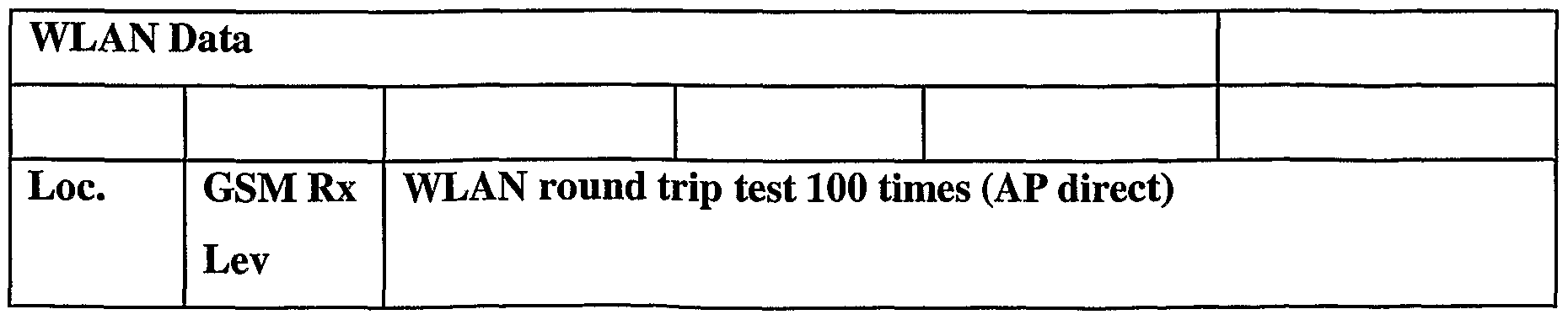
- Table 4 includes a summary of performance data for the system with the coupler 14 interfacing the WLAN with the DAS.
- test results show that a cellular DAS and WLAN integration can be successful when using a coupler in reverse mode as the interfacing element.
- APs 12 would be needed to cover the same office floor. It will be appreciated that the number of APs 12 needed in an integrated solution depends largely on the floor layout and/or the capacity requirements of the WLAN, although it will be recognized that the number of APs 12 can generally be reduced by using an integrated solution. In addition, with the integrated solution, there is no need for any WLAN boosters for single floor coverage. It is also possible to interface multiple APs 12 to the horizontal distribution of the DAS on the same floor if different channels (0-13) are set for each AP 12.
- the number of access points may be reduced to a minimum per floor, thereby allowing for a reduced investment.
- the integration also "enhances the value" of the DAS, because the in-building infrastructure can be reused for providing and extending the WLAN coverage.
- Another benefit is that, by integrating DAS with WLAN, one can minimize the time needed for RF design and survey work for WLAN. There is also low RF radiation from the DAS for WLAN as there are a larger number of distributed antennas. Moreover, unnecessary wiring and fixing of additional WLAN antennas in the ceiling and/or walls is eliminated. Finally, interference levels to adjacent floors and adjacent buildings are kept to a minimum.
- the present invention can be used for WLAN subsystem integration to cellular DAS at any location throughout the world and is applicable for any cellular DAS that is integrated with any WLAN access points using a coupler or tapper in reverse mode.
- the DAS encompasses a distribution' of passive antennas or radiating cable inside any category of building (private, public, or other) such as hotels, restaurants, offices, hospitals, shopping centers, warehouses, underground railway stations and tunnels, offshore platforms, and others using for example: a.
- the invention can be used in connection with any WLAN system subsystem, or similar system, available at present or to be available in the future, working on 2.4-2.5 GHz radio frequency bands adhering to any standard, regardless of manufacturer, vendor, and/or supplier.
- the invention can use a coupler or tapper in reverse mode.
- Standard couplers/tappers are usually marked with arrow markings to indicate the proper direction for the inputs and outputs in order to direct the signal as required by the in- building DAS design.
- these couplers are used in "reverse mode" for at least the following reasons: i. maximize the WLAN signal directed towards the distributed antenna on the floor; ii. maximize the isolation between the WLAN AP and the cellular RBS; and/or iii. minimize insertion loss to the existing or new cellular in-building DAS design.
- reverse mode is generally used herein to indicate that the signal from the WLAN access point AP 12 is connected to the standard coupled port and the output through port (standard through port) is connected to the RBS side and where the input (standard input port) is connected to the distributed antenna side.
- the "reverse mode” functionality can be achieved by re-labeling the ports to make the coupler different from the one used in "reverse mode” in the above-referenced configurations by changing the labeling on the coupler, or by giving a new name to this particular product to achieve the same functionality.
Abstract
Description


Claims
Priority Applications (1)
| Application Number | Priority Date | Filing Date | Title |
|---|---|---|---|
| EP02797714A EP1428398A1 (en) | 2001-09-04 | 2002-09-04 | Integration of wireless lan and cellular distributed antenna |
Applications Claiming Priority (4)
| Application Number | Priority Date | Filing Date | Title |
|---|---|---|---|
| US31729101P | 2001-09-04 | 2001-09-04 | |
| US60/317,291 | 2001-09-04 | ||
| US10/234,082 US7082320B2 (en) | 2001-09-04 | 2002-08-30 | Integration of wireless LAN and cellular distributed antenna |
| US10/234,082 | 2002-08-30 |
Publications (1)
| Publication Number | Publication Date |
|---|---|
| WO2003021995A1 true WO2003021995A1 (en) | 2003-03-13 |
Family
ID=26927539
Family Applications (1)
| Application Number | Title | Priority Date | Filing Date |
|---|---|---|---|
| PCT/SE2002/001584 WO2003021995A1 (en) | 2001-09-04 | 2002-09-04 | Integration of wireless lan and cellular distributed antenna |
Country Status (3)
| Country | Link |
|---|---|
| US (1) | US7082320B2 (en) |
| EP (1) | EP1428398A1 (en) |
| WO (1) | WO2003021995A1 (en) |
Cited By (1)
| Publication number | Priority date | Publication date | Assignee | Title |
|---|---|---|---|---|
| CN1298144C (en) * | 2003-06-17 | 2007-01-31 | 联想(北京)有限公司 | A method for implementing WLAN piconet networking |
Families Citing this family (89)
| Publication number | Priority date | Publication date | Assignee | Title |
|---|---|---|---|---|
| US6842459B1 (en) | 2000-04-19 | 2005-01-11 | Serconet Ltd. | Network combining wired and non-wired segments |
| JP4022121B2 (en) * | 2002-10-07 | 2007-12-12 | 松下電器産業株式会社 | Integrated radio communication system, mobile communication system, switching apparatus, radio terminal, and communication method |
| US20040100930A1 (en) * | 2002-11-25 | 2004-05-27 | Foxcom Wireless | WLAN distributed antenna system |
| SE525090C2 (en) * | 2002-12-02 | 2004-11-30 | Telia Ab | Adaptively passive distributed antenna system |
| US20050170779A1 (en) * | 2003-10-14 | 2005-08-04 | Greg Tangonan | Power monitoring circuitry for wireless fidelity (WiFi) |
| IL159838A0 (en) | 2004-01-13 | 2004-06-20 | Yehuda Binder | Information device |
| US20070110074A1 (en) * | 2004-06-04 | 2007-05-17 | Bob Bradley | System and Method for Synchronizing Media Presentation at Multiple Recipients |
| US20080229335A1 (en) * | 2004-06-04 | 2008-09-18 | Apple Computer, Inc. | Network media device |
| US8797926B2 (en) | 2004-06-04 | 2014-08-05 | Apple Inc. | Networked media station |
| US8443038B2 (en) | 2004-06-04 | 2013-05-14 | Apple Inc. | Network media device |
| US10972536B2 (en) | 2004-06-04 | 2021-04-06 | Apple Inc. | System and method for synchronizing media presentation at multiple recipients |
| US7286848B2 (en) * | 2004-06-30 | 2007-10-23 | Richard P Vireday | Method and apparatus to provide tiered wireless network access |
| CN100421400C (en) * | 2005-04-07 | 2008-09-24 | 华为技术有限公司 | Integrative access system of wireless and wired network |
| US20070099667A1 (en) * | 2005-10-28 | 2007-05-03 | P.G. Electronics Ltd. | In-building wireless enhancement system for high-rise with emergency backup mode of operation |
| US20070143825A1 (en) * | 2005-12-21 | 2007-06-21 | Goffin Glen P | Apparatus and method of tiered authentication |
| US7831222B1 (en) * | 2006-02-24 | 2010-11-09 | Clear Channel Management Services, Inc. | Method and apparatus for improving the isolation characteristics of HD radio combiners |
| US8493590B2 (en) * | 2006-03-24 | 2013-07-23 | Broadcom Corporation | System and method for transmitting high throughput data between multiple devices |
| US7787823B2 (en) | 2006-09-15 | 2010-08-31 | Corning Cable Systems Llc | Radio-over-fiber (RoF) optical fiber cable system with transponder diversity and RoF wireless picocellular system using same |
| US7848654B2 (en) | 2006-09-28 | 2010-12-07 | Corning Cable Systems Llc | Radio-over-fiber (RoF) wireless picocellular system with combined picocells |
| US8873585B2 (en) | 2006-12-19 | 2014-10-28 | Corning Optical Communications Wireless Ltd | Distributed antenna system for MIMO technologies |
| US8111998B2 (en) | 2007-02-06 | 2012-02-07 | Corning Cable Systems Llc | Transponder systems and methods for radio-over-fiber (RoF) wireless picocellular systems |
| US20100054746A1 (en) | 2007-07-24 | 2010-03-04 | Eric Raymond Logan | Multi-port accumulator for radio-over-fiber (RoF) wireless picocellular systems |
| CN101868923B (en) | 2007-09-24 | 2015-04-01 | 松下航空电子公司 | System and method for receiving broadcast content on a mobile platform during travel |
| US8175459B2 (en) | 2007-10-12 | 2012-05-08 | Corning Cable Systems Llc | Hybrid wireless/wired RoF transponder and hybrid RoF communication system using same |
| WO2009081376A2 (en) | 2007-12-20 | 2009-07-02 | Mobileaccess Networks Ltd. | Extending outdoor location based services and applications into enclosed areas |
| US8509990B2 (en) | 2008-12-15 | 2013-08-13 | Panasonic Avionics Corporation | System and method for performing real-time data analysis |
| US9673904B2 (en) | 2009-02-03 | 2017-06-06 | Corning Optical Communications LLC | Optical fiber-based distributed antenna systems, components, and related methods for calibration thereof |
| JP5480916B2 (en) | 2009-02-03 | 2014-04-23 | コーニング ケーブル システムズ リミテッド ライアビリティ カンパニー | Fiber optic based distributed antenna system, components, and related methods for calibration thereof |
| JP2012517190A (en) | 2009-02-03 | 2012-07-26 | コーニング ケーブル システムズ リミテッド ライアビリティ カンパニー | Fiber optic based distributed antenna system, components and related methods for monitoring and configuration thereof |
| EP2441229B1 (en) | 2009-06-11 | 2020-05-06 | Panasonic Avionics Corporation | System and method for providing security aboard a moving platform |
| US8548330B2 (en) | 2009-07-31 | 2013-10-01 | Corning Cable Systems Llc | Sectorization in distributed antenna systems, and related components and methods |
| US9016627B2 (en) | 2009-10-02 | 2015-04-28 | Panasonic Avionics Corporation | System and method for providing an integrated user interface system at a seat |
| US8280259B2 (en) | 2009-11-13 | 2012-10-02 | Corning Cable Systems Llc | Radio-over-fiber (RoF) system for protocol-independent wired and/or wireless communication |
| EP2514062B1 (en) | 2009-12-14 | 2017-11-01 | Panasonic Avionics Corporation | System and method for providing dynamic power management |
| US8275265B2 (en) | 2010-02-15 | 2012-09-25 | Corning Cable Systems Llc | Dynamic cell bonding (DCB) for radio-over-fiber (RoF)-based networks and communication systems and related methods |
| CN102971214B (en) | 2010-04-27 | 2016-01-13 | 松下航空电子公司 | For connection support system and the method for user interface facilities |
| US20110268446A1 (en) | 2010-05-02 | 2011-11-03 | Cune William P | Providing digital data services in optical fiber-based distributed radio frequency (rf) communications systems, and related components and methods |
| US9525488B2 (en) | 2010-05-02 | 2016-12-20 | Corning Optical Communications LLC | Digital data services and/or power distribution in optical fiber-based distributed communications systems providing digital data and radio frequency (RF) communications services, and related components and methods |
| WO2012024247A1 (en) | 2010-08-16 | 2012-02-23 | Corning Cable Systems Llc | Remote antenna clusters and related systems, components, and methods supporting digital data signal propagation between remote antenna units |
| CA2807848C (en) | 2010-09-10 | 2019-10-01 | Panasonic Avionics Corporation | Integrated user interface system and method |
| US9252874B2 (en) | 2010-10-13 | 2016-02-02 | Ccs Technology, Inc | Power management for remote antenna units in distributed antenna systems |
| CN203504582U (en) | 2011-02-21 | 2014-03-26 | 康宁光缆系统有限责任公司 | Distributed antenna system and power supply apparatus for distributing electric power thereof |
| EP2702710A4 (en) | 2011-04-29 | 2014-10-29 | Corning Cable Sys Llc | Determining propagation delay of communications in distributed antenna systems, and related components, systems and methods |
| CN103609146B (en) | 2011-04-29 | 2017-05-31 | 康宁光缆系统有限责任公司 | For increasing the radio frequency in distributing antenna system(RF)The system of power, method and apparatus |
| CN103733664B (en) | 2011-07-11 | 2017-10-24 | 康普技术有限责任公司 | Method and apparatus for managing distributing antenna system |
| BR112014006129A2 (en) | 2011-09-15 | 2017-04-11 | Andrew Wireless Systems Gmbh | configuration subsystem for telecommunication systems |
| EP2661828B1 (en) | 2011-09-16 | 2016-03-23 | Andrew Wireless Systems GmbH | Integrated intermodulation detection sub-system for telecommunications systems |
| EP2832012A1 (en) | 2012-03-30 | 2015-02-04 | Corning Optical Communications LLC | Reducing location-dependent interference in distributed antenna systems operating in multiple-input, multiple-output (mimo) configuration, and related components, systems, and methods |
| WO2013162988A1 (en) | 2012-04-25 | 2013-10-31 | Corning Cable Systems Llc | Distributed antenna system architectures |
| US8923755B2 (en) | 2012-04-29 | 2014-12-30 | Techmer Ltd. | Radio repeater system |
| EP2883416A1 (en) | 2012-08-07 | 2015-06-17 | Corning Optical Communications Wireless Ltd. | Distribution of time-division multiplexed (tdm) management services in a distributed antenna system, and related components, systems, and methods |
| EP3614561A1 (en) | 2012-09-14 | 2020-02-26 | Andrew Wireless Systems GmbH | Uplink path integrity detection in distributed antenna systems |
| US9913147B2 (en) | 2012-10-05 | 2018-03-06 | Andrew Wireless Systems Gmbh | Capacity optimization sub-system for distributed antenna system |
| US9455784B2 (en) | 2012-10-31 | 2016-09-27 | Corning Optical Communications Wireless Ltd | Deployable wireless infrastructures and methods of deploying wireless infrastructures |
| WO2014085115A1 (en) | 2012-11-29 | 2014-06-05 | Corning Cable Systems Llc | HYBRID INTRA-CELL / INTER-CELL REMOTE UNIT ANTENNA BONDING IN MULTIPLE-INPUT, MULTIPLE-OUTPUT (MIMO) DISTRIBUTED ANTENNA SYSTEMS (DASs) |
| US9647758B2 (en) | 2012-11-30 | 2017-05-09 | Corning Optical Communications Wireless Ltd | Cabling connectivity monitoring and verification |
| EP2944131A1 (en) | 2013-01-08 | 2015-11-18 | Whoop Wireless LLC | A system, a device and a method for adjusting signal strength in a distributed amplifier system |
| CA2841685C (en) | 2013-03-15 | 2021-05-18 | Panasonic Avionics Corporation | System and method for providing multi-mode wireless data distribution |
| EP3008828B1 (en) | 2013-06-12 | 2017-08-09 | Corning Optical Communications Wireless Ltd. | Time-division duplexing (tdd) in distributed communications systems, including distributed antenna systems (dass) |
| EP3008515A1 (en) | 2013-06-12 | 2016-04-20 | Corning Optical Communications Wireless, Ltd | Voltage controlled optical directional coupler |
| US9247543B2 (en) | 2013-07-23 | 2016-01-26 | Corning Optical Communications Wireless Ltd | Monitoring non-supported wireless spectrum within coverage areas of distributed antenna systems (DASs) |
| US9661781B2 (en) | 2013-07-31 | 2017-05-23 | Corning Optical Communications Wireless Ltd | Remote units for distributed communication systems and related installation methods and apparatuses |
| US9385810B2 (en) | 2013-09-30 | 2016-07-05 | Corning Optical Communications Wireless Ltd | Connection mapping in distributed communication systems |
| US9178635B2 (en) | 2014-01-03 | 2015-11-03 | Corning Optical Communications Wireless Ltd | Separation of communication signal sub-bands in distributed antenna systems (DASs) to reduce interference |
| US9775123B2 (en) | 2014-03-28 | 2017-09-26 | Corning Optical Communications Wireless Ltd. | Individualized gain control of uplink paths in remote units in a distributed antenna system (DAS) based on individual remote unit contribution to combined uplink power |
| US9357551B2 (en) | 2014-05-30 | 2016-05-31 | Corning Optical Communications Wireless Ltd | Systems and methods for simultaneous sampling of serial digital data streams from multiple analog-to-digital converters (ADCS), including in distributed antenna systems |
| US9525472B2 (en) | 2014-07-30 | 2016-12-20 | Corning Incorporated | Reducing location-dependent destructive interference in distributed antenna systems (DASS) operating in multiple-input, multiple-output (MIMO) configuration, and related components, systems, and methods |
| US9730228B2 (en) | 2014-08-29 | 2017-08-08 | Corning Optical Communications Wireless Ltd | Individualized gain control of remote uplink band paths in a remote unit in a distributed antenna system (DAS), based on combined uplink power level in the remote unit |
| US9602210B2 (en) | 2014-09-24 | 2017-03-21 | Corning Optical Communications Wireless Ltd | Flexible head-end chassis supporting automatic identification and interconnection of radio interface modules and optical interface modules in an optical fiber-based distributed antenna system (DAS) |
| US9420542B2 (en) | 2014-09-25 | 2016-08-16 | Corning Optical Communications Wireless Ltd | System-wide uplink band gain control in a distributed antenna system (DAS), based on per band gain control of remote uplink paths in remote units |
| US10659163B2 (en) | 2014-09-25 | 2020-05-19 | Corning Optical Communications LLC | Supporting analog remote antenna units (RAUs) in digital distributed antenna systems (DASs) using analog RAU digital adaptors |
| WO2016071902A1 (en) | 2014-11-03 | 2016-05-12 | Corning Optical Communications Wireless Ltd. | Multi-band monopole planar antennas configured to facilitate improved radio frequency (rf) isolation in multiple-input multiple-output (mimo) antenna arrangement |
| WO2016075696A1 (en) | 2014-11-13 | 2016-05-19 | Corning Optical Communications Wireless Ltd. | Analog distributed antenna systems (dass) supporting distribution of digital communications signals interfaced from a digital signal source and analog radio frequency (rf) communications signals |
| US9729267B2 (en) | 2014-12-11 | 2017-08-08 | Corning Optical Communications Wireless Ltd | Multiplexing two separate optical links with the same wavelength using asymmetric combining and splitting |
| WO2016098109A1 (en) | 2014-12-18 | 2016-06-23 | Corning Optical Communications Wireless Ltd. | Digital interface modules (dims) for flexibly distributing digital and/or analog communications signals in wide-area analog distributed antenna systems (dass) |
| WO2016098111A1 (en) | 2014-12-18 | 2016-06-23 | Corning Optical Communications Wireless Ltd. | Digital- analog interface modules (da!ms) for flexibly.distributing digital and/or analog communications signals in wide-area analog distributed antenna systems (dass) |
| US20160249365A1 (en) | 2015-02-19 | 2016-08-25 | Corning Optical Communications Wireless Ltd. | Offsetting unwanted downlink interference signals in an uplink path in a distributed antenna system (das) |
| US10305198B2 (en) | 2015-02-25 | 2019-05-28 | At&T Intellectual Property I, L.P. | Facilitating wireless communications via wireless communication assembly apparatuses |
| US9681313B2 (en) | 2015-04-15 | 2017-06-13 | Corning Optical Communications Wireless Ltd | Optimizing remote antenna unit performance using an alternative data channel |
| US9948349B2 (en) | 2015-07-17 | 2018-04-17 | Corning Optical Communications Wireless Ltd | IOT automation and data collection system |
| US10560214B2 (en) | 2015-09-28 | 2020-02-11 | Corning Optical Communications LLC | Downlink and uplink communication path switching in a time-division duplex (TDD) distributed antenna system (DAS) |
| US10141996B2 (en) | 2015-12-13 | 2018-11-27 | Drone Racing League, Inc. | Communication system with distributed receiver architecture |
| US10236924B2 (en) | 2016-03-31 | 2019-03-19 | Corning Optical Communications Wireless Ltd | Reducing out-of-channel noise in a wireless distribution system (WDS) |
| EP3752925A4 (en) * | 2018-02-16 | 2021-12-01 | CommScope Technologies LLC | Variable upgradable multi-user port of a remote antenna unit |
| US10783929B2 (en) | 2018-03-30 | 2020-09-22 | Apple Inc. | Managing playback groups |
| US11297369B2 (en) | 2018-03-30 | 2022-04-05 | Apple Inc. | Remotely controlling playback devices |
| US10993274B2 (en) | 2018-03-30 | 2021-04-27 | Apple Inc. | Pairing devices by proxy |
| US10614857B2 (en) | 2018-07-02 | 2020-04-07 | Apple Inc. | Calibrating media playback channels for synchronized presentation |
| US11323187B2 (en) * | 2019-10-15 | 2022-05-03 | Fiplex Communications, Inc. | Smart nodes for monitoring a passive distributed antenna system |
Citations (3)
| Publication number | Priority date | Publication date | Assignee | Title |
|---|---|---|---|---|
| US5321736A (en) * | 1992-01-03 | 1994-06-14 | Pcs Microcell International Inc. | Distributed RF repeater arrangement for cordless telephones |
| US5564121A (en) * | 1994-08-18 | 1996-10-08 | Northern Telecom Limited | Microcell layout having directional and omnidirectional antennas defining a rectilinear layout in a building |
| WO2001059874A1 (en) * | 2000-02-12 | 2001-08-16 | Motorola Inc. | Distributed cellular telephone antenna system with adaptive cell configuration |
Family Cites Families (16)
| Publication number | Priority date | Publication date | Assignee | Title |
|---|---|---|---|---|
| US5283789A (en) * | 1992-05-15 | 1994-02-01 | Private Satellite Network, Inc. | Communication system providing data and television signals to PC work stations |
| US5923702A (en) * | 1996-06-10 | 1999-07-13 | Breeze Wireless Communications Ltd. | Frequency hopping cellular LAN system |
| US6223055B1 (en) * | 1997-10-24 | 2001-04-24 | Lucent Technologies, Inc. | Wireless office architecture and method of operation thereof |
| FI105978B (en) * | 1998-05-12 | 2000-10-31 | Nokia Mobile Phones Ltd | Method of connecting a wireless data terminal in a data transmission network and a wireless data terminal |
| US6243581B1 (en) * | 1998-12-11 | 2001-06-05 | Nortel Networks Limited | Method and system for seamless roaming between wireless communication networks with a mobile terminal |
| US6405018B1 (en) * | 1999-01-11 | 2002-06-11 | Metawave Communications Corporation | Indoor distributed microcell |
| US6587479B1 (en) * | 1999-04-21 | 2003-07-01 | Opencell Corp. | Architecture for signal distribution in wireless data network |
| DE19952980A1 (en) * | 1999-11-03 | 2001-05-10 | Schleifring Und App Bau Gmbh | Arrangement for multi-channel signal transmission between moving units |
| US6497656B1 (en) * | 2000-02-08 | 2002-12-24 | General Electric Company | Integrated wireless broadband communications network |
| US7187907B2 (en) * | 2000-05-09 | 2007-03-06 | Bernard Widrow | Simultaneous two-way transmission of information signals in the same frequency band |
| US6659947B1 (en) * | 2000-07-13 | 2003-12-09 | Ge Medical Systems Information Technologies, Inc. | Wireless LAN architecture for integrated time-critical and non-time-critical services within medical facilities |
| US6801767B1 (en) * | 2001-01-26 | 2004-10-05 | Lgc Wireless, Inc. | Method and system for distributing multiband wireless communications signals |
| US6778844B2 (en) * | 2001-01-26 | 2004-08-17 | Dell Products L.P. | System for reducing multipath fade of RF signals in a wireless data application |
| US6771933B1 (en) * | 2001-03-26 | 2004-08-03 | Lgc Wireless, Inc. | Wireless deployment of bluetooth access points using a distributed antenna architecture |
| EP1380184B1 (en) * | 2001-04-06 | 2007-01-24 | Nokia Corporation | Location method and system |
| US6990338B2 (en) * | 2001-06-11 | 2006-01-24 | The Boeing Company | Mobile wireless local area network and related methods |
-
2002
- 2002-08-30 US US10/234,082 patent/US7082320B2/en not_active Expired - Lifetime
- 2002-09-04 EP EP02797714A patent/EP1428398A1/en not_active Withdrawn
- 2002-09-04 WO PCT/SE2002/001584 patent/WO2003021995A1/en not_active Application Discontinuation
Patent Citations (3)
| Publication number | Priority date | Publication date | Assignee | Title |
|---|---|---|---|---|
| US5321736A (en) * | 1992-01-03 | 1994-06-14 | Pcs Microcell International Inc. | Distributed RF repeater arrangement for cordless telephones |
| US5564121A (en) * | 1994-08-18 | 1996-10-08 | Northern Telecom Limited | Microcell layout having directional and omnidirectional antennas defining a rectilinear layout in a building |
| WO2001059874A1 (en) * | 2000-02-12 | 2001-08-16 | Motorola Inc. | Distributed cellular telephone antenna system with adaptive cell configuration |
Cited By (1)
| Publication number | Priority date | Publication date | Assignee | Title |
|---|---|---|---|---|
| CN1298144C (en) * | 2003-06-17 | 2007-01-31 | 联想(北京)有限公司 | A method for implementing WLAN piconet networking |
Also Published As
| Publication number | Publication date |
|---|---|
| US20030087672A1 (en) | 2003-05-08 |
| US7082320B2 (en) | 2006-07-25 |
| EP1428398A1 (en) | 2004-06-16 |
Similar Documents
| Publication | Publication Date | Title |
|---|---|---|
| US7082320B2 (en) | Integration of wireless LAN and cellular distributed antenna | |
| US7937110B2 (en) | Distributed base station system and method for networking thereof and base band unit | |
| EP2544505B1 (en) | Dual WiFi apparatus for wireless Internet and wireless Internet system using the same | |
| US11088544B2 (en) | Intermediate power supply unit for distributing lower voltage power to remote power distribution systems | |
| US20040203704A1 (en) | Indoor wireless voice and data distribution system | |
| US8676261B2 (en) | Base station for mobile communication system | |
| CN103314556A (en) | Power distribution module(s) capable of hot connection and/or disconnection for distributed antenna systems, and related power units, components, and methods | |
| US6310705B1 (en) | Duplex outdoor base station transceiver subsystem utilizing a hybrid system of a high power amplifier and an optic antenna | |
| CN103650385A (en) | Optical fiber-based distributed radio frequency (RF) antenna systems supporting multiple-input, multiple-output (MIMO) configurations, and related components and methods | |
| US9712212B2 (en) | Multiple service distributed-antenna system | |
| AU6543799A (en) | Modular and distributed architecture for a base station transceiver subsystem | |
| KR20120118877A (en) | Wireless transmission system using air-conditioning duct | |
| EP1239600B1 (en) | Wireless communication system using a waveguide | |
| KR19990029554A (en) | Modular, distributed radio architecture and dual carrier access using the same antenna | |
| EP2590472B1 (en) | WiFi apparatus for wireless internet and wireless internet system using the same | |
| Cisco | Overview | |
| US11621776B2 (en) | Systems for low power distribution in a power distribution network | |
| US6889035B2 (en) | Cable-less interconnect architecture for effecting blind coupling of diplexer to radio transceiver | |
| KR102120673B1 (en) | Distributed antenna system and improving signal quality method thereof | |
| Salo | Radio Frequency Design and Performance Optimization of an In-Building Private LTE Network | |
| US7190973B1 (en) | Method for reconfiguring base station equipment to relieve blocking in a heavily utilized cell sector | |
| Lamborn et al. | Using fiber optic-to-radio frequency (RF) conversion for communication-based train control | |
| Chung | A radio communications network for voice and data in underground mines | |
| KR20030033824A (en) | System for monitoring and controlling of Mobile Communication Base Station | |
| CN115995692A (en) | Antenna subsystem and networking system |
Legal Events
| Date | Code | Title | Description |
|---|---|---|---|
| AK | Designated states |
Kind code of ref document: A1 Designated state(s): AE AG AL AM AT AU AZ BA BB BG BR BY BZ CA CH CN CO CR CU CZ DE DK DM DZ EC EE ES FI GB GD GE GH GM HR HU ID IL IN IS JP KE KG KP KR KZ LC LK LR LS LT LU LV MA MD MG MK MN MW MX MZ NO NZ OM PH PL PT RO RU SD SE SG SI SK SL TJ TM TN TR TT TZ UA UG UZ VC VN YU ZA ZM ZW Kind code of ref document: A1 Designated state(s): AE AG AL AM AT AU AZ BA BB BG BY BZ CA CH CN CO CR CU CZ DE DM DZ EC EE ES FI GB GD GE GH HR HU ID IL IN IS JP KE KG KP KR LC LK LR LS LT LU LV MA MD MG MN MW MX MZ NO NZ OM PH PL PT RU SD SE SG SI SK SL TJ TM TN TR TZ UA UG UZ VC VN YU ZA ZM |
|
| AL | Designated countries for regional patents |
Kind code of ref document: A1 Designated state(s): GH GM KE LS MW MZ SD SL SZ UG ZM ZW AM AZ BY KG KZ RU TJ TM AT BE BG CH CY CZ DK EE ES FI FR GB GR IE IT LU MC PT SE SK TR BF BJ CF CG CI GA GN GQ GW ML MR NE SN TD TG Kind code of ref document: A1 Designated state(s): GH GM KE LS MW MZ SD SL SZ TZ UG ZM ZW AM AZ BY KG KZ MD RU TJ TM AT BE BG CH CY CZ DE DK EE ES FI FR GB GR IE IT LU MC NL PT SE SK TR BF BJ CF CG CI CM GA GN GQ GW ML MR NE SN TD TG |
|
| 121 | Ep: the epo has been informed by wipo that ep was designated in this application | ||
| DFPE | Request for preliminary examination filed prior to expiration of 19th month from priority date (pct application filed before 20040101) | ||
| WWE | Wipo information: entry into national phase |
Ref document number: 2002797714 Country of ref document: EP |
|
| WWP | Wipo information: published in national office |
Ref document number: 2002797714 Country of ref document: EP |
|
| NENP | Non-entry into the national phase |
Ref country code: JP |
|
| WWW | Wipo information: withdrawn in national office |
Country of ref document: JP |