US9730200B2 - System and method for transmission and reception of control channels - Google Patents
System and method for transmission and reception of control channels Download PDFInfo
- Publication number
- US9730200B2 US9730200B2 US13/436,657 US201213436657A US9730200B2 US 9730200 B2 US9730200 B2 US 9730200B2 US 201213436657 A US201213436657 A US 201213436657A US 9730200 B2 US9730200 B2 US 9730200B2
- Authority
- US
- United States
- Prior art keywords
- wireless node
- pdcch
- subframe
- resource
- communications controller
- Prior art date
- Legal status (The legal status is an assumption and is not a legal conclusion. Google has not performed a legal analysis and makes no representation as to the accuracy of the status listed.)
- Active, expires
Links
Images


Classifications
-
- H04W72/042—
-
- H—ELECTRICITY
- H04—ELECTRIC COMMUNICATION TECHNIQUE
- H04W—WIRELESS COMMUNICATION NETWORKS
- H04W72/00—Local resource management
- H04W72/20—Control channels or signalling for resource management
- H04W72/23—Control channels or signalling for resource management in the downlink direction of a wireless link, i.e. towards a terminal
-
- H—ELECTRICITY
- H04—ELECTRIC COMMUNICATION TECHNIQUE
- H04W—WIRELESS COMMUNICATION NETWORKS
- H04W24/00—Supervisory, monitoring or testing arrangements
- H04W24/10—Scheduling measurement reports ; Arrangements for measurement reports
-
- H—ELECTRICITY
- H04—ELECTRIC COMMUNICATION TECHNIQUE
- H04W—WIRELESS COMMUNICATION NETWORKS
- H04W48/00—Access restriction; Network selection; Access point selection
- H04W48/08—Access restriction or access information delivery, e.g. discovery data delivery
- H04W48/12—Access restriction or access information delivery, e.g. discovery data delivery using downlink control channel
-
- H04W72/0406—
-
- H—ELECTRICITY
- H04—ELECTRIC COMMUNICATION TECHNIQUE
- H04W—WIRELESS COMMUNICATION NETWORKS
- H04W72/00—Local resource management
- H04W72/20—Control channels or signalling for resource management
Definitions
- the present disclosure relates generally to digital communications, and more particularly to a system and method for transmission and reception of control channels.
- BS base station
- BTS base transceiver station
- NB Node B
- eNB evolved NB
- Access Point communications controller
- HomoNet homogenous network
- LPNs Low Power Nodes
- lower power base stations can be deployed to, e.g., cover lobbies of hotels, portions of shopping malls, and the like.
- the coverage of such a base station is referred to as a pico cell.
- the base station transmit power is even lower, e.g., to cover a single residential unit, the coverage of such a base station is referred to as a femto cell.
- a network comprising regular base stations and pico cells and/or femto cells is referred to as a heterogeneous network (HetNet).
- HetNet heterogeneous network
- HetNets present new challenges to the deployment of a cellular system.
- the cellular layout may not be as regular as for a HomoNet since it is dependent on the hot spot locations.
- a LPN is located close to another base station. The close proximity can create a high level of interference for both user equipment (UE) (also known as mobile station (MS), terminal, user, subscriber, wireless node, and the like) and BSs.
- UE user equipment
- MS mobile station
- BSs base station
- transmissions from the BS comprise both data channels and control channels.
- the interference can affect both the data channels and control channels. While solutions exist to mitigate interference on the data channels, no such solution has been defined yet for the control channels.
- Example embodiments of the present disclosure which provide a system and method for transmission and reception of control channels.
- a method for transmitting control information to a wireless node includes determining, by a communications controller, a first resource assignment parameter according to a pseudo-random sequence derived from an identifier, and mapping, by the communications controller, using the first resource assignment parameter, a demodulation reference signal associated with the wireless node onto a first resource located in a data region of a subframe.
- the method also includes mapping, by the communications controller, modulated control information associated with the wireless node onto a second resource located in the data region of the subframe, and transmitting, by the communications controller, the subframe to the wireless node.
- a method for receiving control information includes receiving, by a wireless node, a subframe, and determining, by the wireless node, a first resource assignment parameter according to a pseudo-random sequence derived from an identifier.
- the method also includes determining, by the wireless node, using the first resource assignment parameter, a demodulation reference signal associated with the wireless node, the demodulation reference signal located in a first resource located in a data region of the subframe, and demodulating, by the wireless node, modulated control information using the demodulation reference signal to produce the control information, the modulated control information located in a second resource located in the data region.
- a communications controller includes a processor, and a transmitter operatively coupled to the processor.
- the processor determines a first resource assignment parameter according to a pseudo-random sequence derived from an identifier, maps using the first resource assignment parameter, a demodulation reference signal associated with a wireless node onto a first resource located in a data region of a subframe, and maps modulated control information associated with the wireless node onto a second resource located in the data region of the subframe.
- the transmitter transmits the subframe to the wireless node.
- a wireless node in accordance with another example embodiment of the present disclosure, includes a receiver, and a processor operatively coupled to the receiver.
- the receiver receives a subframe.
- the processor determines a first resource assignment parameter according to a pseudo-random sequence derived from an identifier, determines using the first resource assignment parameter, a demodulation reference signal associated with the wireless node, the demodulation reference signal located in a first resource located in a data region of the subframe, and demodulates modulated control information using the demodulation reference signal to produce control information, the modulated control information located in a second resource located in the data region.
- One advantage of an embodiment is that the use of resource assignment parameters provides orthogonality to control channels, permitting a larger number of control channels to be transmitted.
- the use of resource assignment parameters also enables the use of advanced transmission techniques.
- a further advantage of an embodiment is that the resource assignment parameters are selected according to a pseudo-random sequence, which provides an additional degree of randomness, as well as not requiring a significant amount of coordination between communicating devices. Hence, communications overhead is reduced.
- FIG. 1 illustrates an example communications system according to example embodiments described herein;
- FIGS. 2 a through 2 d illustrate example subframes according to example embodiments described herein;
- FIG. 3 illustrates an example a RB pair used to carry a U-PDCCH and a PDSCH according to example embodiments described herein;
- FIG. 4 illustrates an example flow diagram of UE operations in processing an RB comprising a U-PDCCH and a PDSCH according to example embodiments described herein;
- FIG. 5 a illustrates a first example DMRS of a RB pair with 12 subcarriers in a subframe according to example embodiments described herein;
- FIG. 5 b illustrates a second example DMRS of a RB pair with 12 subcarriers in a subframe according to example embodiments described herein;
- FIG. 6 illustrates an example flow diagram of eNB operations in DMRS pattern selection for U-PDCCH and PDSCH multiplexing according to example embodiments described herein;
- FIGS. 7 a and 7 b illustrate example communications systems according to example embodiments described herein;
- FIG. 8 a illustrates an example flow diagram of eNB operations in transmitting a first control channel (e.g., a U-PDCCH) and a second channel (e.g., a PDSCH) according to example embodiments described herein;
- a first control channel e.g., a U-PDCCH
- a second channel e.g., a PDSCH
- FIG. 8 b illustrates a flow diagram of UE operations in receiving a first control channel (e.g., a U-PDCCH) and an example second channel (e.g., a PDSCH) according to example embodiments described herein;
- a first control channel e.g., a U-PDCCH
- an example second channel e.g., a PDSCH
- FIG. 8 c illustrates an example flow diagram of UE operations in receiving a first control channel multiplexed with a second control channel according to example embodiments described herein;
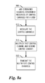
- FIG. 9 a illustrates an example flow diagram of eNB operations in transmitting a control channel with an associated reference signal according to example embodiments described herein;
- FIG. 9 b illustrates an example flow diagram of UE operations in receiving a control channel with an associated reference signal according to example embodiments described herein;
- FIG. 10 illustrates an example first communications device according to example embodiments described herein.
- FIG. 11 illustrates an example second communications device according to example embodiments described herein.
- One embodiment of the disclosure relates to transmission and reception of control channels. For example, at an eNB, the eNB determines a resource assignment parameter according to a pseudo-random sequence that is derived from an identifier and then map a demodulation reference associated with the wireless node onto a first resource located in the data region of a subframe using the resource assignment parameter. The eNB also maps modulated control information associated with the wireless node onto a second resource in the data region of the subframe and transmits the subframe.
- HetNet deployment including a 3GPP LTE compliant communications system.
- the disclosure may also be applied, however, to other HetNet deployments, such as those including 3GPP LTE-Advanced, WiMAX, and the like, compliant communications systems, as well as HetNet deployments with non-standards compliant communications systems.
- the PDSCH may be used to carry data information.
- the PDCCH may convey control information about a particular PDSCH, such as resource allocation information, modulation and coding information, and information about a Physical Uplink Shared Channel (PUSCH).
- the PDCCH may be considered to be a first type of control channel.
- the control information for PDSCH and PUSCH can be referred as resource allocation information.
- the PDCCH may be located in the first several symbols (e.g., one to four symbols) of a subframe. These PDCCH-bearing symbols may be referred to as a control domain or a control region. Other symbols in the subframe may be used for data transmission, and may be referred to herein as a data domain or a data region. Hence the PDCCH is located in control region while the PDSCH is located in data region.
- control channels there may be other control channels, such as a Physical Hybrid Indicator Channel (PHICH), which is used to transmit ACK/NACK in response to uplink data transmission, and the Physical Control Format Indicator Channel (PCFICH), which is used to indicate the number of symbols of a control region in a subframe.
- PHICH Physical Hybrid Indicator Channel
- PCFICH Physical Control Format Indicator Channel
- an eNB locates a new type of control channel(s), which may be located in the data region, control region, or both of a subframe may be considered. More specifically, when the control channel is located in the data region, a second control region may be defined and uses a portion of the data region.
- the second control region comprising some combination of time and frequency resources, e.g., resource elements, with a group of resource elements forming a resource block (RB). For example, in one 3GPP LTE configuration, 84 resource elements make up a RB. Similarly, a group of resource elements forms a control channel element (CCE).
- CCE control channel element
- 36 resource elements make up a control channel element.
- At least part of the time and frequency resources (or simply, resources) of the second control region may be used for transmitting control information in the new type of control channel, e.g., a second type of control channel.
- the resources of the second control region that are not used for transmitting control information may be used for other purposes, such as transmitting data, e.g., on the PDSCH.
- One or more resource elements or parts of resource blocks (RBs) from the data region may be allocated for the second control region.
- a new second type control channel a UE Physical Downlink Control Channel (U-PDCCH)
- U-PDCCH UE Physical Downlink Control Channel
- the second channel may carry resource assignments for UEs or other network nodes such as relay nodes.
- the second control region may carry channels analogous to those carried in the first control region, such as the physical hybrid automatic repeat requested indicator channel (PHICH), and the like.
- PHICH physical hybrid automatic repeat requested indicator channel
- a prefix of “U-” may be added to indicate the analogous channel in the second control region, such as the “U-PHICH”.
- control information such as resource assignments (also commonly referred to as resource allocation assignments), configuration information, power control, codebook information, HARQ information, and the like, may be referred to as control information.
- the format and content of these analogous channels may be different from the first control region.
- control channel types including a third type of control channel, which may be transmitted in both the first control region and in the second control region.
- the information in the two control regions may be the same or it may be different.
- FIG. 1 illustrates a communications system 100 .
- Communications system 100 includes an evolved NodeB (eNB) 105 , which may also be commonly referred to as a controller, a communications controller, a base station, a NodeB, and the like.
- eNB evolved NodeB
- Communications system 100 also includes a plurality of User Equipment (UE), such as UE 110 , 112 , and 120 .
- UE User Equipment
- a UE may also be commonly referred to as a mobile, mobile station, subscriber, user, terminal, wireless node, and the like.
- the communication system may include other entities such as Relay Node (RN) 115 .
- the RN may serve one or more UEs, such as UE 120 .
- Communications between eNB 105 and a given UE may occur over a link that comprises a Un downlink (DL) channel and an Un uplink (UL) channel.
- UEs not directly served by the RN and RNs may be multiplexed together using and may be allocated different RBs.
- the UE resource assignments are transmitted on the PDCCH.
- communications systems may employ multiple eNBs capable of communicating with a number of UEs, only one eNB, a plurality of UEs, and one RN are illustrated for simplicity.
- FIG. 2 a illustrates a first subframe 200 .
- Subframe 200 comprises a first control region 205 and a data region 210 .
- Subframe 200 shows an example for a multicarrier modulation system.
- first control region 205 may include control signaling, such as a PDCCH
- data region 210 may include data as well as control signaling, which may include a PDSCH, as well as new control channels, such as a U-PHICH or a U-PDCCH.
- First control region 205 may also be called a PDCCH control region and may contain the first type of control channels.
- the new control channels (e.g., the second type of control channels) are located in a new control region 215 (also commonly referred to as a second control region 215 ), which may be inside data region 210 .
- New control region 215 can also be called the U-PDCCH control region.
- data region 210 may be used to transmit data, no data is shown in FIG. 2 a .
- second control region 215 is located in data region 210
- PDCCH is located in first control region 205 .
- the representation of the various channels and regions in FIG. 2 a is logical in nature with no direct relationship to an actual mapping of specific physical resources.
- the resources comprising second control region 215 may be distributed in frequency and are not restricted to be contiguous in frequency.
- Second control region 215 may also be time multiplexed with data, and for instance, may occupy only the first or the second slot of a subframe.
- second control region 215 may not necessarily start immediately after first control region 205 , but may be offset by one or more symbols.
- Second control region 215 may consist of Physical RBs (PRBs) or Virtual RBs (VRBs), either localized or distributed.
- PRBs and the VRBs comprise a plurality of resource elements.
- FIG. 2 b illustrates a second subframe 230 .
- Subframe 230 comprises a first control region 235 and a data region 240 .
- first control region 235 may include control signaling, such as a PDCCH
- data region 240 may include data without control signaling.
- First control region 235 may also be called a PDCCH control region.
- FIG. 2 c illustrates a third subframe 260 .
- Subframe 260 comprises a data region 265 .
- data region 265 may include data as well as control signaling, which may include a PDSCH, as well as new control channels, such as a U-PDCCH or a U-PHICH.
- the new control channels are located in a new control region 270 , which may be inside data region 265 .
- New control region 270 may be used to transmit data, but no data is shown in FIG. 2 c .
- new control region 270 is located in data region 265 . It is noted that subframe 260 has no PDCCH since a first control region is absent.
- FIG. 2 d illustrates a fourth subframe 280 .
- Subframe 280 comprises a control region 285 and a data region 290 .
- control region 285 may include control signaling
- data region 290 may include data as well as control signaling.
- the new control channel may be located in a first new control region 292 , which may be inside control region 285 , as well as in a second new control region 294 , which may be inside data region 290 .
- a relay PDCCH may be used to transmit control information to notify RNs of the DL and/or UL grants on the link between the eNB 105 and the RN 115 .
- R-PDCCH a relay PDCCH
- the design of the R-PDCCH does not account for some unique properties of the access link between the eNB and the UE such as:
- each U-PDCCH can have its own reference signal for channel estimation during demodulation, thereby allowing more advanced transmission schemes, such as beam forming or precoding, to be used.
- DMRS demodulation reference signal
- the use of the DMRS may also create a more efficient control channel that can take advantage of technologies such as dynamic link adaptation, frequency selective resource allocation, and Multiple Input, Multiple Output (MIMO) transmission.
- MIMO Multiple Input, Multiple Output
- Some of these improvements may also be used with the PDCCH (e.g., link adaptation), but some, e.g., Multi-User MIMO (MU-MIMO), is better suited for U-PDCCH.
- MU-MIMO Multi-User MIMO
- the design of the U-PDCCH should consider the details of multiplexing. In order to facilitate multiplexing, the U-PDCCH should be considered using RBs within the data region since the PDSCH is assigned in units of RBs, or more specifically in RB pairs where one element (RB) of the RB pair is mapped to the first slot of a subframe while another element is mapped to the second slot of a subframe.
- the number and location of available REs in each RB are determined after considering the size of the PDCCH control region and the control signaling overhead, e.g., reference symbols, primary synchronization signal (PSS), secondary synchronization signal (SSS), physical broadcast channel (PBCH), and the like.
- PSS primary synchronization signal
- SSS secondary synchronization signal
- PBCH physical broadcast channel
- FIG. 3 illustrates a RB pair 300 used to carry a U-PDCCH and a PDSCH.
- RB pair 300 shows an example embodiment wherein a U-PDCCH may occupy a first slot 305 in a subframe and a PDSCH may occupy a second slot 310 in the subframe.
- the two RBs in a subframe may be referred to as a RB pair.
- the U-PDCCH may be multiplexed with other channels.
- the U-PDCCH may be multiplexed with U-PDCCH of other UEs. It may be possible to multiplex multiple U-PDCCHs through spatial multiplexing, with each U-PDCCH using different antenna port(s) for DMRS.
- the U-PDCCH may also be multiplexed with the R-PDCCH of a relay node.
- the U-PDCCH may also be multiplexed with the PDSCH of the same or other UEs since the U-PDCCH can have the same structure as the PDSCH. However, alignment of the U-PDCCH and the PDSCH being multiplexed may be needed.
- the U-PDCCH may be multiplexed with the PDSCH.
- high order modulation such as 16-QAM (quadrature amplitude modulation)
- a low aggregation level i.e., a high code rate
- a UE receiving the RB or the RB pair may need to process the information contained therein.
- a RB or a RB pair can contain both the U-PDCCH and PDSCH.
- the U-PDCCH and PDSCH should belong to the same UE.
- FIG. 4 illustrates a flow diagram of UE operations in processing a resource, e.g., a RB) comprising a U-PDCCH and a PDSCH.
- UE operations may be indicative of operations occurring in a UE, such as UE 110 and UE 120 , as the UE processes a RB that includes a U-PDCCH and a PDSCH multiplexed together.
- the UE operations may begin with the UE determining an aggregation level (denoted “L”) of the resource, e.g., the RB (block 405 ).
- the UE may determine the aggregation level by selecting an aggregation level from several different aggregation levels.
- the UE may select 1, 2, 4, or 8 as the aggregation level.
- the UE may determine the resources, e.g., the RBs, to examine according to the aggregation level (block 410 ).
- the UE may be informed by the eNB a set of resources, e.g., a set of RBs, where control information may be sent.
- the eNB may inform the UE which resources, e.g., RBs, belong to a UE-specific search space and a common search space. It is noted for the U-PDCCH that some resources, e.g., RBs, in the UE-specific search space may also be in the common search space. There may be rules that state aggregation levels are used per search space.
- a similar set of rules may be defined for the U-PDCCH.
- the UE may examine a subset of resources, e.g., REs, of the resources, e.g., RBs, from block 410 (block 415 ).
- the subset of REs of the RBs may correspond to the U-PDCCH, in other words, the subset of REs may contain the U-PDCCH.
- the subset of REs of the RBs may or may not be a contiguous block of REs.
- the REs corresponding to the U-PDCCH may be distributed (or interleaved) throughout the RBs according to a distribution rule or an interleaving rule.
- the UE may select another resource, such as a RB or RB pair, and then return to block 405 to select an aggregation level.
- the UE may process the contents of the decoded U-PDCCH (block 425 ). As an example, the UE may process the contents of the decoded U-PDCCH to determine if the U-PDCCH was assigned to the UE. If the U-PDCCH was assigned to the UE, the UE may consider that some of the remaining resources (e.g., REs of the RB or RB pair not used to convey the U-PDCCH) may be used for a PDSCH (block 430 ). The UE may perform additional processing on the remaining resources, e.g., REs.
- REs e.g., REs.
- U-PDCCH may be multiplexed with PDSCH of the same or different UE in the spatial domain.
- the U-PDCCH and the PDSCH transmissions may use different DMRS if U-PDCCH and PDSCH belong to different UEs.
- the U-PDCCH may be multiplexed with a R-PDCCH. Since the U-PDCCH and R-PDCCH have basically the same structure, they can be multiplexed together. However, if the R-PDCCH and U-PDCCH have different search spaces, there may be collisions between search spaces of the two channels. These collisions may be similar to collisions occurring between various PDCCHs in the PDCCH control region. If there is a collision, the collision may block an entire resource, e.g., a RB, over the subframe. Fortunately, in some cases, the collision problem may not be significant, e.g., when both the U-PDCCH and the R-PDCCH use DMRS, the search space basically consists of adjacent resources, such as adjacent RBs.
- a channel such as a R-PDCCH uses DMRS and no interleaving
- multiplexing can be achieved by fitting the R-PDCCH in between resources, such as RBs, used for U-PDCCH.
- resources such as RBs
- the probability of collisions can be fairly high. However, the probability can be lowered by ensuring that UE-specific and RN-specific search spaces are sufficiently large.
- a U-PDCCH may be multiplexed with R-PDCCH in the spatial domain. The U-PDCCH and the R-PDCCH transmissions may then use different DMRS ports.
- UE 1 and UE 2 may be allocated in the same resource for the U-PDCCH, but with different precoding vectors for multiple antennas.
- the U-PDCCH may be scrambled by a cell-specific scrambling code, and the DMRS may be generated also by a cell-specific scrambling code.
- Multiple DMRS may be orthogonal in time, frequency, and/or code domain, for example, orthogonal codes can be applied (modulated) to the DMRS symbols.
- Multiple DMRS patterns/ports may correspond to multiple antenna ports. In other words, the data transmitted on an antenna port has the same precoding vector as that of the reference signal of the same antenna port.
- DMRS multiplexing of multiple control channels
- multiple U-PDCCHs multiple U-PDCCHs
- multiple PDSCHs multiple PDSCHs
- multiple R-PDCCHs multiple R-PDCCHs
- resource assignment parameters such as other reference signals, precoding vectors, antenna ports, antenna port number, orthogonal patterns, scrambling codes, and the like, may be used to support the multiplexing of multiple control channels. Therefore the discussion of DMRS as a resource assignment parameter should not be construed as being limiting to either the spirit or the scope of the examples discussed herein.
- FIG. 5 a illustrates a first example DMRS of a resource pair, such as a RB pair, with 12 subcarriers in a subframe.
- Cross-hatched boxes such as boxes 505 and 510 , illustrate REs used for a DMRS.
- FIG. 5 b illustrates a second example DMRS of resource pair, such as a RB pair, with 12 subcarriers in a subframe.
- the two example DMRS are orthogonal in the time-frequency domain. In addition to being orthogonal in the time-frequency domain, code-division orthogonality can also be used to create additional DMRS patterns.
- DMRS patterns of antenna ports 7 and 8 occupy the resources shown in FIG. 5 a in case of a normal subframe for a normal cyclic prefix.
- DMRS patterns of antenna ports 9 and 10 occupy the resources shown in FIG.
- DMRS patterns of antenna ports 7 and 8 are code-division orthogonal.
- DMRS patterns of antenna ports 7 , 8 , 11 , and 12 are code-division orthogonal while DMRS of antenna ports 9 , 10 , 13 , and 14 are code-division orthogonal.
- the DMRS antenna ports for the two U-PDCCHs should be different.
- the scrambling codes for the two U-PDCCHs should also be different to randomize the interference.
- a scrambling code can be applied on the encoded bits by modulo-2 addition (in binary field GF(2)) as in shown TS 36.211 Release-8 of 3GPP LTE specification, or a scrambling code can be applied onto the modulated symbols in a manner similar to that in code division multiple access (CDMA) systems.
- CDMA code division multiple access
- Signaling by the eNB may be used to indicate which scrambling code and/or which antenna port for DMRS is used for the U-PDCCH of a UE.
- UE 1 has a scrambling code and/or an antenna port of DMRS
- UE 2 has another scrambling code and/or another antenna port for DMRS.
- UE 1 and UE 2 may be spatially multiplexed at the same resource depending on channel conditions.
- UEs with the same scrambling code and/or antenna port of DMRS should not be spatially multiplexed.
- one UE may be paired with another UE for spatial multiplexing of U-PDCCH if the two UEs have different scrambling codes and/or antenna ports of DMRS configurations. This may be a constraint on spatial multiplexing of U-PDCCH of multiple UEs.
- the capacity of U-PDCCH may be increased.
- the remaining REs (the unoccupied REs) may be allocated to one of UEs which has a U-PDCCH allocated in the first slot of the RB pair, or the remaining REs may be allocated to a UE without a U-PDCCH in the RB pair if the UE knows which REs have been allocated to U-PDCCH.
- R-PDCCH It may be possible to provide a performance improvement over an R-PDCCH as well, where the R-PDCCH and a PDSCH can share DMRS of antenna port 7 .
- the techniques presented herein show how to use and assign DMRS for the U-PDCCH and PDSCH. To ensure remaining REs may be allocated to PDSCH of a UE, a set of DMRS patterns different from the set of DMRS patterns for U-PDCCH should be allocated to the UE depending on the layers in the spatial domain for data channel.
- the UE may be unaware if another UE's (e.g., UE 2 ) U-PDCCH is multiplexed in the same resource as its own U-PDCCH. Therefore, the UE 1 may be unaware which DMRS patterns were allocated to the UE 2 's U-PDCCH.
- FIG. 6 illustrates a flow diagram of eNB operations in DMRS pattern selection for U-PDCCH and PDSCH multiplexing.
- eNB operations may be indicative of operations occurring in an eNB, such as eNB 105 , as the eNB selects DMRS patterns for a U-PDCCH and a PDSCH that are to be multiplexed.
- eNB operations may begin with the eNB determining (or scheduling) by computing, decoding, receiving, retrieving, and the like, information about antenna ports for a U-PDCCH (block 605 ) and a PDSCH (block 610 ) to ensure that the DMRS patterns for the U-PDCCH and the PDSCH of a UE will not collide another UE's DMRS patterns for its U-PDCCH (block 615 ). It is noted that when two UEs have different antenna port allocations for their respective U-PDCCH, the antenna port allocations may also be used for the UEs PDSCHs.
- the DMRS of antenna ports 9 and 10 may be allocated for the U-PDCCHs of two UEs (such as UE 1 and UE 2 ). Additionally, antenna port(s) 7 and/or 8 of DMRS may be allocated for a PDSCH of a UE (such as UE 1 ).
- antenna port 9 of DMRS may also be reused for PDSCH.
- antenna ports 7 and/or 8 and 9 may be used for PDSCH to support more spatial multiplexing layers for UE 1 .
- the control signaling of U-PDCCH indicates that the antenna port of DMRS is to be used for U-PDCCH is also used for PDSCH demodulation, then the PDSCH can share the DMRS of U-PDCCH.
- the PDSCH may share the DMRS of U-PDCCH if U-PDCCH and PDSCH are in a same RB pair as indicated by block 615 .
- antenna ports 7 and 8 of DMRS are signaled for PDSCH in the U-PDCCH and antenna port 10 of DMRS is used for U-PDCCH
- a technique may be defined so that antenna port 7 (or 8 ) is replaced by antenna 10 in the RB pair with U-PDCCH and PDSCH.
- antenna ports 10 and 8 (or 7 ) are used for PDSCH.
- a U-PDCCH may be multiplexed with another U-PDCCH
- a U-PDCCH may be multiplexed with a R-PDCCH
- a PDSCH may be multiplexed with a R-PDCCH
- two R-PDCCHs may be multiplexed, and the like. Therefore, the discussion of multiplexing a U-PDCCH and a PDSCH should not be construed as being limiting to either the scope or the spirit of the examples disclosed herein.
- the U-PDCCH may not always use antenna port 7 of DMRS for channel estimation.
- Another antenna port of DMRS may be allocated for channel estimation.
- the antenna port information can be provided using signaling or some predefined rule, for example, determined using a function of a UE identifier, such as, a UE-ID.
- a procedure may be defined to share an antenna port of DMRS for PDSCH and U-PDCCH.
- a signaled antenna port of DMRS for PDSCH may be replaced by an antenna port of DMRS for U-PDCCH.
- signaled antenna ports of DMRS for PDSCH may include an antenna port of DMRS for U-PDCCH.
- the signaling may indicate contiguously indexed antenna ports of DMRS for PDSCH for a UE, but the starting index may be the same as the antenna port of DMRS for U-PDCCH of this UE.
- signaling may indicate four antenna ports of DMRS are provided for PDSCH, and the index of antenna port of DMRS of U-PDCCH is 8 , therefore, ports 8 , 9 , 10 , and 11 are the antenna ports provided for PDSCH transmission.
- UEs with different antenna ports of DMRS for U-PDCCH and PDSCH may be spatially multiplexed.
- UE 1 has antenna port 7 of DMRS for U-PDCCH while UE 2 has antenna port 9 of DMRS for U-PDDCH. If signaling indicates there are two antenna ports of DMRS for PDSCH of UE 1 , then antenna ports 7 and 8 of DMRS are allocated to PDSCH of UE 1 . Similarly, if signaling indicates that UE 2 has two antenna ports of DMRS for PDSCH, then antenna ports 9 and 10 of DMRS are allocated to UE 2 for PDSCH.
- Another method that may be used to multiplex U-PDCCH for two UEs is to signal a set of scrambling codes and/or antenna ports of DMRS.
- the flexibility of pairing for U-PDCCHs of different UEs may be increased at the cost of increasing number of blind decoding since the UE may need to blindly detect which scrambling code and/or antenna port of DMRS is used for its U-PDCCH. If the number of U-PDCCH candidates with different resource allocations is kept the same, the total number of blind decoding would be doubled with dual scrambling codes and/or dual antenna ports of DMRS.
- the resource allocation for U-PDCCH candidates of a UE may be reduced by one half. Resulting in a reduction in the number of candidates in time-frequency domain, which may result in more allocation collisions for U-PDCCH. In other words, blocking probability may increase.
- One solution to reduce blind decoding by the UE is to pseudo-randomly assign scrambling code and/or antenna port(s) of DMRS.
- a UE-specific pseudo random sequence such as a Gold sequence may be used to select scrambling code and/or antenna ports of DMRS.
- the total number of scrambling codes and/or antenna ports of DMRS that can be used for this UE may be predetermined and signaled to UE, or predefined in a technical or industrial standard.
- randomly selecting a scrambling code and/or antenna port of DMRS for a UE can be based on a specific time interval, such as a subframe, a specified number of subframes, a frame, a specified number of frames, and the like.
- the eNB may transmit the U-PDCCH with UE-specific scrambling code and/or antenna port of DMRS. If the UE detects (e.g., through blind detection) one scrambling code and/or one antenna port of DMRS, the total number of blind detection attempts is not increased.
- a UE may be paired with different UEs to increase the flexibility of spatial multiplexing.
- a portion, such as a bit, of the pseudo random sequence may indicate one of two candidates, for example, a “0” may indicate the first UE, and a “1” may indicate the second UE.
- n bits from the pseudo random sequence may select one of m options.
- a formula such as b mod m, where b is a non-negative integer less than 2 n may be used to determine what to blind decode.
- the value b which may be UE dependent, the value n (a number of bits from a pseudo random sequence) and the number of options m, which can indicate the total number of scrambling codes and/or antenna ports allocated for a UE, may be signaled to a UE by UE-dedicated signaling or broadcast signaling.
- While signaling may indicate a set of scrambling codes and/or a set of DMRS patterns, a subset of DMRS patterns may be allocated. As an example, if antenna ports 7 and 8 are signaled to be used for DMRS of a UE, then the REs for pattern 9 and 10 may be reserved for data transmission, or the patterns 9 and 10 can be for DMRS of data channel.
- FIGS. 7 a and 7 b illustrate example communications systems.
- the communications systems may use the same cell-id for multiple remote radio heads (RRHs) or may use different cell-id for multiple RRHs.
- the scrambling code used for U-PDCCH may correspond to an identifier, such as a cell-identifier (cell-id), a cell group identifier, a site group identifier, a site identifier, and the like.
- the scrambling code for an antenna port may be determined by the cell-id and the antenna port index together.
- the signaling may convey a set of scrambling codes used for U-PDCCH modulation.
- the signaling may convey a set of DMRS patterns.
- the set of DMRS patterns may be orthogonal, or the set of DMRS patterns may be divided into multiple subsets and within each subset, the DMRS patterns may be orthogonal.
- the signaling may be provided using broadcast signaling or dedicated signaling.
- each UE may have a unique scrambling code(s) and/or DMRS pattern(s).
- the scrambling codes may be cell-specific, for example, there can be a set of scrambling codes in a cell where each UE in the cell may be assigned unique scrambling code(s) selected from the set of scrambling codes.
- the scrambling codes may be the same. Different scrambling codes may be used for generating more DMRS patterns in addition to orthogonal codes. For example, with two different scrambling codes, there may be 16 DMRS patterns. Signaling may be used to inform UEs about a scrambling code used for DMRS.
- a transmission method for U-PDCCH which has a characteristic that a reference signal that corresponds to the U-PDCCH is transmitted, is used.
- the reference signal may be used for demodulation of the U-PDCCH by the UE.
- the reference signal may be determined by a reference signal pattern.
- the pattern that is transmitted for the U-PDCCH may be determined by a pseudo-random sequence.
- the generation of the pseudo-random sequence can be initialized using a seed.
- the seed may be based on a UE-specific parameter, such as a UE identifier (UE-ID).
- UE-ID UE identifier
- the seed may be a cell-specific parameter.
- the seed may be based on a combination of the UE-ID and cell-ID. For each subframe, slot, RB, and/or U-PDCCH candidate, a corresponding element in the pseudo-random sequence may be used for determining the DMRS pattern for subframe, slot, RB, and/or U-PDCCH candidate.
- the pseudo-random sequence may vary depending on the subframe, slot, RB, and/or U-PDCCH candidates. Due to UE complexity reasons, the same element in the pseudo-random sequence may be used for different U-PDCCH candidates for a given subframe and/or slot. As an example, the candidates of U-PDCCH for a UE in a subframe may all have the same reference signal pattern.
- a signaling technique having a characteristic that the signaling may inform a UE about a set of reference signal patterns for each subframe and/or slot, and/or for each U-PDCCH, according to a pseudo-random sequence.
- a reference sequence pattern corresponding to an element of the pseudo-random sequence may be used for the U-PDCCH, or a set of reference sequence patterns may be predefined in a technical specification.
- a reception technique of U-PDCCH where the UE detects all the candidates of U-PDCCH for this UE.
- the UE may detect a plurality of candidates corresponding to a plurality of different aggregation levels (which corresponds to the numbers of REs for U-PDCCH), a plurality of candidates corresponding to different DCI formats, a plurality of candidates corresponding to different resource allocations for U-PDCCH, and the like.
- the reception technique may be characterized by a reference signal from a set of reference patterns that is used for demodulation of a U-PDCCH candidate according to a pseudo-random sequence.
- FIG. 8 a illustrates a flow diagram of eNB operations in transmitting a first control channel (e.g., a U-PDCCH) and a second channel (e.g., a PDSCH).
- eNB operations may be indicative of operations occurring in an eNB, such as eNB 105 , as the eNB transmits a first control channel and a second channel.
- a transmission technique used for transmitting a U-PDCCH which has the characteristic that a scrambling code sequence corresponding to a U-PDCCH is used for U-PDCCH transmission.
- the scrambling code sequence may be from the set of scrambling code sequences associated with a UE.
- Which scrambling code sequence is used out of the set of scrambling code sequences may be determined by a pseudo-random sequence.
- the pseudo-random sequence may be controlled (seeded) by UE-ID and/or cell-ID, and the like.
- the UE-ID and/or the cell ID, and the like may be shared with the UE.
- the scrambling code sequence applied for U-PDCCH can correspond to a reference signal pattern for the U-PDCCH.
- eNB operations may begin with the eNB determining resource assignment parameters, e.g., DMRS, reference signals, antenna ports, antenna port numbers, precoding vectors, orthogonal patterns, scrambling codes, and the like, for the first control channel (e.g., the U-PDCCH) and as well as the resource assignment parameters for the second channel (e.g., the PDSCH) to be transmitted to a UE(s) (block 805 ).
- the eNB may determine the resource assignment parameters of the first control channel and the second channel using a pseudo-random sequence, such as a scrambling code, associated with the UE(s).
- the pseudo-random sequence may be generated using a sequence generator.
- the sequence generator may be initialized according to an identifier associated with the UE.
- a cell specific identifier may be used to initialize the sequence generator.
- UEs in a cell may utilize the same resource assignment parameter(s).
- a UE specific identifier may be used to initialize the sequence generator.
- different UEs within a cell may utilize different resource assignment parameter(s).
- a combination of a UE specific identifier and a cell specific identifier may be used to initialize the sequence generator.
- the UE specific identifier and/or the cell specific identifier may be shared with the UE.
- a different sequence generator may be used for different UEs, a group of UEs may use the same sequence generator, UEs operating in a single cell may use the same sequence generator, and the like. If there are multiple UEs, the eNB may repeat block 805 for each of the multiple UEs.
- the eNB may modulate control information for the first control channel and the second channel for the UE(s) (block 810 ). If there are multiple UEs, the eNB may multiplex the modulated control information for the first control channel and the modulated control information for the second channel for several UEs into a resource, such as a RB or a RB pair, of a subframe according to the resource assignment parameters (block 815 ). The eNB may transmit the subframe including the multiplexed first control channel and the multiplexed second channel for the UE(s) (block 820 ).
- the multiplexing of the first control channel and the second channel according to the resource assignment parameter may be as described below. If the resource assignment parameter comprises a DMRS or some other reference signal, the eNB may multiplex the modulated control information for the first control channel, the modulated control information for the second channel, a first DMRS determined for the first control channel, and a second DMRS determined for the second channel onto a RB or a RB pair.
- the resource assignment parameter comprises a DMRS or some other reference signal
- the eNB may precode the modulated control information for the first control channel with a first precoding vector, precode the modulated control information for the second channel with a second precoding vector, and then multiplex the precoded, modulated control information for the first control channel and the precoded, modulated control information for the second channel.
- the resource assignment parameter comprises an orthogonal pattern
- the eNB may operate in a manner similar to the above described process for the precoding vector, but instead of precoding the modulated control information, the eNB may multiply or add the orthogonal pattern with the modulated control information. It is noted that multiple resource assignment parameters may be combined together.
- a first example resource assignment parameter may comprise a precoding vector and a DMRS
- a second example resource assignment parameter may comprise an orthogonal vector and antenna ports.
- UE operations may also be applied to a situation involving the multiplexing of a first control channel of a first UE and a second control channel (or a second channel) of a second UE.
- UE operations for multiplexing control channels for multiple UEs may begin with the eNB determining resource assignment parameters, e.g., DMRS, reference signals, antenna ports, precoding vectors, orthogonal patterns, and the like, for the first control channel of the first UE and for the second control channel of the second UE (block 805 ).
- the eNB may use a pseudo-random sequence, such as a scrambling code, associated with the first UE and the second UE to determine the respective resource assignment parameters.
- the eNB may modulate the control information for the first control channel and the second control channel for the UEs (block 810 ).
- the eNB may multiplex the modulated control information for the first control channel and the modulated control information for the second control channel into a RB or a RB pair of a subframe according to the resource assignment parameters (block 815 ). It is noted that the multiplexing of the modulated control information according to the resource assignment parameter may proceed as discussed above.
- the eNB may transmit the subframe including the multiplexed first control channel and the multiplexed second control channel to the UEs (block 820 ).
- FIG. 8 b illustrates a flow diagram of UE operations in receiving a first control channel (e.g., a U-PDCCH) and a second channel (e.g., a PDSCH).
- UE operations may be indicative of operations occurring in a UE, such as UE 110 and UE 120 , as the UE receives a first control channel and a second channel.
- a reception method of the first control channel may be characterized by a scrambling code sequence applied to a candidate of the first control channel, e.g., the U-PDCCH, where the scrambling code is selected from a set of scrambling code sequences.
- the scrambling code sequence used may be determined by a pseudo-random sequence.
- the pseudo-random sequence may be controlled (seeded) by parameters such as UE-ID and/or cell-ID, and the like.
- a shared antenna port of DMRS which may be shared by a U-PDCCH and PDSCH in a RB or RB pair, may be signaled to the UE (or determined by the UE according to a predefined technique using a parameter, such as UE-ID).
- the UE operations may begin with the UE receiving a subframe (block 850 ).
- the subframe may include a control channel for the UE.
- the UE may determine resource assignment parameters, e.g., DMRS, reference signals, antenna ports, precoding vectors, orthogonal patterns, and the like, for the first control channel (block 855 ).
- the UE may determine the resource assignment parameters for the first control channel through signaling provided by the eNB or through the use of a pseudo-random sequence generated by a sequence generator that may be initialized (seeded) by an identifier such as UE-ID and/or cell-ID, and the like.
- the UE may use the resource assignment parameters of the first control channel to assist in detecting the first control channel (block 860 ).
- the UE may determine the resource assignment parameters for the second control channel (block 865 ). As discussed previously, the UE may determine the resource assignment parameters of the second channel through signaling provided by the eNB or through the use of a pseudo-random sequence generated by a sequence generator that may be initialized (seeded) by parameters such as UE-ID and/or cell-ID, and the like. In some instances, the resource assignment parameters for the second channel may be the same or a subset of the resource assignment parameters for the first control channel.
- the resource assignment parameters, such as DMRS (e.g., the antenna ports of the DMRS) of the second channel may be determined from the resource assignment parameters, such as DMRS (e.g., an index of antenna ports of the DMRS) of the first control channel or signaling in the first control channel.
- DMRS e.g., an index of antenna ports of the DMRS
- an antenna port(s) shared by the first control channel and the second channel may be signaled to the UE, for example, using higher layer signaling or Layer One and/or Layer Two signaling.
- the UE may use the resource assignment parameters of the second channel to detect the PDSCH (block 870 ).
- the detecting of the first control channel using resource assignment parameters and the detecting of the second channel using resource assignment parameters may be as described below.
- the resource assignment parameter comprises a DMRS or some other reference signal
- the UE may utilize its knowledge of the DMRS or some other reference signal to assist in detecting the multiplexed first control channel and/or the multiplexed second channel.
- the resource assignment parameter comprises a precoding vector
- the UE may apply a precoding vector for the first control channel to its receive antenna array prior to receiving the first control channel.
- the UE may also apply a precoding vector for the second channel to its receive antenna array prior to receiving the second control channel. It is noted that multiple resource assignment parameters may be combined together.
- FIG. 8 c illustrates a flow diagram of UE operations in receiving a first control channel multiplexed with a second control channel.
- UE operations may be indicative of operations occurring in a UE, such as UE 110 and UE 120 , as the UE receives a first control channel that has been multiplexed with a second control channel.
- the UE operations may begin with the UE receiving a subframe (block 880 ).
- the subframe may include a control channel for the UE.
- the UE may determine resource assignment parameters, e.g., DMRS, reference signals, antenna ports, precoding vectors, orthogonal patterns, and the like, for the first control channel (block 885 ).
- the UE may determine the resource assignment parameters for the first control channel through signaling provided by the eNB or through the use of a pseudo-random sequence controlled (seeded) by parameters such as UE-ID and/or cell-ID, and the like.
- the UE may use the resource assignment parameters of the U-PDCCH to assist in demodulating the control information from the U-PDCCH (block 890 ).
- a reception method of U-PDCCH and PDSCH which has the characteristic that determining an antenna port of DMRS for U-PDCCH, and determining an antenna port of DMRS for PDSCH in the same RB pair as for U-PDCCH, and the antenna port of DMRS for U-PDCCH is shared with PDSCH, uses the DMRS for channel estimation of U-PDCCH and PDSCH, as well as demodulation and decoding of U-PDCCH and PDSCH.
- the antenna port of DMRS for U-PDCCH may be determined through decoding signaling transmitted by eNB or through a randomization scheme utilizing a pseudo-random sequence.
- the antenna ports of DMRS for PDSCH may be determined by contiguous indices with the index of the antenna port of DMRS for U-PDCCH being a starting antenna port.
- FIG. 9 a illustrates a flow diagram of eNB operations in transmitting a control channel with an associated reference signal.
- eNB operations may be indicative of operations occurring in an eNB, such as eNB 105 , as the eNB transmits a control channel with an associated reference signal, e.g., a DMRS.
- eNB operations may begin with the eNB determining a resource assignment parameter, such as a DMRS, a reference signal, and the like, for the control channel (block 905 ).
- a resource assignment parameter such as a DMRS, a reference signal, and the like
- the eNB may determine some or all of the resource assignment parameters of the control channel using a pseudo-random sequence, such as a scrambling code, associated with the UE(s).
- the pseudo-random sequence may be generated using a sequence generator.
- the eNB may map a DMRS, to be used to assist the UE in demodulating the control channel, onto a first resource or first resources of a subframe, e.g., a data region of the subframe (block 910 ).
- the DMRS used may be selected according to the resource assignment parameter or may be based on the resource assignment parameter.
- the resource assignment parameter may be an index of a DMRS selected out of a set of DRMSs.
- the resource assignment parameter may be a reference sequence that may be used as the DMRS.
- the eNB may map modulated control information onto a second resource or second resources of the subframe, e.g., the data region of the subframe (block 915 ). It is noted that the modulated control information and the DMRS may be associated with an antenna port.
- the eNB may transmit the subframe to the UE (block 920 ).
- a general structure for a DL channel has steps of precoding complex-valued modulation symbols on each layer for transmission on the antenna ports to resources, e.g., REs.
- resources e.g., REs.
- UE specific reference signals such as DMRS, may be transmitted only on resources, e.g., RBs, upon which corresponding PDSCH are mapped.
- DMRS may be transmitted on resources, e.g., RBs, upon which the U-PDCCH are mapped.
- a precoding vector that is used for the U-PDCCH may also be used for the DMRS.
- the precoding vector may be said to be associated with the DMRS and the U-PDCCH.
- the UE may use the DMRS for wireless channel estimation, which may then be used to demodulate the received U-PDCCH.
- FIG. 9 b illustrates a flow diagram of UE operations in receiving a control channel with an associated reference signal.
- UE operations may be indicative of operations occurring in a UE, such as UE 110 and UE 120 , as the UE receives a control channel with an associated reference signal.
- the UE operations may begin with the UE receiving a subframe (block 955 ).
- the UE may determine a resource assignment parameter, such as a DMRS, a reference signal, and the like, for the control channel (block 960 ).
- the UE may determine some or all of the resource assignment parameters of the control channel using a pseudo-random sequence, such as a scrambling code, associated with the UE.
- the pseudo-random sequence may be generated using a sequence generator.
- the UE may determine a DMRS according to the resource assignment parameter (block 965 ).
- the resource assignment parameter may be an index of a DMRS selected out of a set of DRMSs.
- the resource assignment parameter may be a reference sequence that may be used as the DMRS.
- the UE may demodulate the modulated control information in the control channel using the DMRS to produce the control information (block 970 ).
- FIG. 10 illustrates a first communications device 1000 .
- Communications device 1000 may be used to implement various ones of the embodiments discussed herein.
- a transmitter 1005 is configured to transmit information and a receiver 1010 is configured to receive information.
- a UE controller 1020 is configured to determine which control channel(s) a UE is to monitor. The determination may be based on a number of factors, such as UE capability, communications system capability, and so on.
- An assignment unit 1025 is configured to assign a UE to monitor a control channel(s). For example, assignment unit 1025 may assign a UE to monitor a PDCCH, a U-PDCCH, or both PDCCH and U-PDCCH.
- a search space controller 1030 is configured to specify a search space or a set of search spaces (possibly out of a number of possible search spaces) where a UE may search to find a U-PDCCH.
- a parameter unit 1035 is configured to select and/or assign communications parameters, such as rank, coding rate, modulation scheme, antenna port, and so forth, to a UE.
- a signaling unit 1040 is configured to generate messages and/or indications to be transmitted to a UE, where the messages and/or indications convey channel assignments, parameters, and so on.
- a resource grant unit 1045 is configured to grant resources to UEs.
- a random sequence unit 1050 is configured to generate a pseudo-random number according to a pseudo-random number sequence and an initialization value (e.g., a seed). Random sequence unit 1050 may be implemented as a sequence generator.
- a multiplexing unit 1055 is configured to select a resource assignment parameter, e.g., DMRS, reference signals, antenna ports, precoding vectors, orthogonal patterns, and the like, according to the pseudo-random number sequence. Multiplexing unit 1055 is also configured to multiplex information onto resource elements according to the resource assignment parameter.
- a memory 1060 is configured to store information, such as channel assignment, parameters, pseudo-random sequences, seeds, resource assignment parameters, etc.
- the elements of communications device 1000 may be implemented as specific hardware logic blocks.
- the elements of communications device 1000 may be implemented as software executing in a processing unit such as processor (e.g., microprocessor or digital signal processor), controller, application specific integrated circuit, or so on.
- the elements of communications device 1000 may be implemented as a combination of software and/or hardware.
- transmitter 1005 and receiver 1010 may be implemented as a specific hardware block, while UE controller 1020 , assignment unit 1025 , search space controller 1030 , parameter unit 1035 , signaling unit 1040 , resource grant unit 1045 , random sequence unit 1050 , and multiplexing unit 1055 may be software modules executing in a microprocessor, such as processor 1015 , or a custom circuit or a custom compiled logic array of a field programmable logic array.
- FIG. 11 illustrates a second communications device 1100 .
- Communications device 1100 may be used to implement various ones of the embodiments discussed herein.
- a transmitter 1105 is configured to transmit information and a receiver 1110 is configured to receive information.
- a detector 1120 is configured to detect transmissions by searching (e.g., by blind detection) a search space for the transmissions.
- a search space controller 1125 is configured to control the searches made by communications device 1100 based on search space(s) specified by an eNB controlling the communications device 1100 .
- a channel select unit 1130 is configured to select a control channel to monitor based on instructions from the eNB, power measurements, performance metrics, and so on.
- a parameter unit 1135 is configured to process communications parameters provided by the eNB.
- a random sequence unit 1140 is configured to generate a pseudo-random number according to a pseudo-random number sequence and an initialization value (e.g., a seed).
- a multiplexing unit 1145 is configured to demultiplex information from resource elements according to a resource assignment parameter, e.g., DMRS, reference signals, antenna ports, precoding vectors, orthogonal patterns, and the like, according to the pseudo-random number.
- a memory 1150 is configured to store information, such as channel assignment, parameters, pseudo-random sequences, seeds, resource assignment parameters, etc.
- the elements of communications device 1100 may be implemented as specific hardware logic blocks. In an alternative, the elements of communications device 1100 may be implemented as software executing in a processing unit such as processor (e.g., microprocessor or digital signal processor), controller, application specific integrated circuit, or so on. In yet another alternative, the elements of communications device 1100 may be implemented as a combination of software and/or hardware.
- processor e.g., microprocessor or digital signal processor
- controller e.g., application specific integrated circuit, or so on.
- the elements of communications device 1100 may be implemented as a combination of software and/or hardware.
- transmitter 1105 and receiver 1120 may be implemented as a specific hardware block, while detector 1120 , search space controller 1125 , channel select unit 1130 , parameter unit 1135 , random sequence unit 1140 , and multiplexing unit 1145 may be software modules executing in a microprocessor or a custom circuit or a custom compiled logic array of a field programmable logic array.
Abstract
A method for transmitting control information to a wireless node includes determining, by a communications controller, a first resource assignment parameter according to a pseudo-random sequence derived from an identifier, and mapping, by the communications controller, using the first resource assignment parameter, a demodulation reference signal associated with the wireless node onto a first resource located in a data region of a subframe. The method also includes mapping, by the communications controller, modulated control information associated with the wireless node onto a second resource located in the data region of the subframe, and transmitting, by the communications controller, the subframe to the wireless node.
Description
This application claims the benefit of U.S. Provisional Applications: No. 61/471,049, filed on Apr. 1, 2011, entitled “System and Method for Signaling a Location of a Control Channel,” No. 61/470,940, filed on Apr. 1, 2011, entitled “System and Method for Transmission and Reception of Control Channels in a Communications System,” No. 61/471,055, filed on Apr. 1, 2011, entitled “System and Method for Transmission and Reception of Control Channels,” and No. 61/471,061, filed on Apr. 1, 2011, entitled “System and Method for Transmission and Reception of Control Channels,” which applications are hereby incorporated herein by reference.
This application is related to the following co-assigned patent applications: Ser. No. 13/434,449, filed Mar. 29, 2012, entitled “System and Method for Transmission and Reception of Control Channels in a Communications System”; Ser. No. 13/436,375, filed Mar. 30, 2012, entitled “System and Method for Signaling a Location of a Control Channel”; and Ser. No. 13/436,590, filed Mar. 30, 2012, entitled “System and Method for Transmitting and Receiving Control Channels” which applications are hereby incorporated herein by reference.
The present disclosure relates generally to digital communications, and more particularly to a system and method for transmission and reception of control channels.
Wireless telephony systems have traditionally been deployed using the concept of a cell, with one base station (BS) (also known as base transceiver station (BTS), Node B (NB), evolved NB (eNB), Access Point, communications controller, and the like) covering a given geographic area. BSs having the same or similar transmit power are typically used. In addition, in order to maximize coverage and to maintain interference at a reasonable level, careful site planning is used. A network deployed in such a manner is usually referred to as a homogenous network (HomoNet).
While such a deployment is optimal when the user density is uniform, in practice, it has serious shortcomings because the user density and traffic demand are rarely uniform. For example, in rural areas, roads are typically the only area where users are present. In urban or suburban areas, there are locations (hot spots) where the traffic demand is higher: such locations may comprise shopping malls, hotels, conference centers, and the like.
In order to improve coverage and user satisfaction, it may be advantageous to cover these hot spots of traffic demands with Low Power Nodes (LPNs). For instance, lower power base stations can be deployed to, e.g., cover lobbies of hotels, portions of shopping malls, and the like. The coverage of such a base station is referred to as a pico cell. When the base station transmit power is even lower, e.g., to cover a single residential unit, the coverage of such a base station is referred to as a femto cell. A network comprising regular base stations and pico cells and/or femto cells is referred to as a heterogeneous network (HetNet).
HetNets present new challenges to the deployment of a cellular system. In particular, the cellular layout may not be as regular as for a HomoNet since it is dependent on the hot spot locations. In particular, it may well happen that a LPN is located close to another base station. The close proximity can create a high level of interference for both user equipment (UE) (also known as mobile station (MS), terminal, user, subscriber, wireless node, and the like) and BSs.
In the Third Generation Partnership Project (3GPP) Long Term Evolution (LTE) Release-10 technical standards, transmissions from the BS comprise both data channels and control channels. The interference can affect both the data channels and control channels. While solutions exist to mitigate interference on the data channels, no such solution has been defined yet for the control channels.
Example embodiments of the present disclosure which provide a system and method for transmission and reception of control channels.
In accordance with an example embodiment of the present disclosure, a method for transmitting control information to a wireless node is provided. The method includes determining, by a communications controller, a first resource assignment parameter according to a pseudo-random sequence derived from an identifier, and mapping, by the communications controller, using the first resource assignment parameter, a demodulation reference signal associated with the wireless node onto a first resource located in a data region of a subframe. The method also includes mapping, by the communications controller, modulated control information associated with the wireless node onto a second resource located in the data region of the subframe, and transmitting, by the communications controller, the subframe to the wireless node.
In accordance with another example embodiment of the present disclosure, a method for receiving control information is provided. The method includes receiving, by a wireless node, a subframe, and determining, by the wireless node, a first resource assignment parameter according to a pseudo-random sequence derived from an identifier. The method also includes determining, by the wireless node, using the first resource assignment parameter, a demodulation reference signal associated with the wireless node, the demodulation reference signal located in a first resource located in a data region of the subframe, and demodulating, by the wireless node, modulated control information using the demodulation reference signal to produce the control information, the modulated control information located in a second resource located in the data region.
In accordance with another example embodiment of the present disclosure, a communications controller is provided. The communications controller includes a processor, and a transmitter operatively coupled to the processor. The processor determines a first resource assignment parameter according to a pseudo-random sequence derived from an identifier, maps using the first resource assignment parameter, a demodulation reference signal associated with a wireless node onto a first resource located in a data region of a subframe, and maps modulated control information associated with the wireless node onto a second resource located in the data region of the subframe. The transmitter transmits the subframe to the wireless node.
In accordance with another example embodiment of the present disclosure, a wireless node is provided. The wireless node includes a receiver, and a processor operatively coupled to the receiver. The receiver receives a subframe. The processor determines a first resource assignment parameter according to a pseudo-random sequence derived from an identifier, determines using the first resource assignment parameter, a demodulation reference signal associated with the wireless node, the demodulation reference signal located in a first resource located in a data region of the subframe, and demodulates modulated control information using the demodulation reference signal to produce control information, the modulated control information located in a second resource located in the data region.
One advantage of an embodiment is that the use of resource assignment parameters provides orthogonality to control channels, permitting a larger number of control channels to be transmitted. The use of resource assignment parameters also enables the use of advanced transmission techniques.
A further advantage of an embodiment is that the resource assignment parameters are selected according to a pseudo-random sequence, which provides an additional degree of randomness, as well as not requiring a significant amount of coordination between communicating devices. Hence, communications overhead is reduced.
For a more complete understanding of the present disclosure, and the advantages thereof, reference is now made to the following descriptions taken in conjunction with the accompanying drawing, in which:
The operating of the current example embodiments and the structure thereof are discussed in detail below. It should be appreciated, however, that the present disclosure provides many applicable inventive concepts that can be embodied in a wide variety of specific contexts. The specific embodiments discussed are merely illustrative of specific structures of the disclosure and ways to operate the disclosure, and do not limit the scope of the disclosure.
One embodiment of the disclosure relates to transmission and reception of control channels. For example, at an eNB, the eNB determines a resource assignment parameter according to a pseudo-random sequence that is derived from an identifier and then map a demodulation reference associated with the wireless node onto a first resource located in the data region of a subframe using the resource assignment parameter. The eNB also maps modulated control information associated with the wireless node onto a second resource in the data region of the subframe and transmits the subframe.
The present disclosure will be described with respect to example embodiments in a specific context, namely a HetNet deployment including a 3GPP LTE compliant communications system. The disclosure may also be applied, however, to other HetNet deployments, such as those including 3GPP LTE-Advanced, WiMAX, and the like, compliant communications systems, as well as HetNet deployments with non-standards compliant communications systems.
For 3GPP LTE Release 10 (Release-10) and earlier technical standards, both a Physical Downlink Control Channel (PDCCH) and a Physical Downlink Shared Channel (PDSCH) are defined. The PDSCH may be used to carry data information. The PDCCH may convey control information about a particular PDSCH, such as resource allocation information, modulation and coding information, and information about a Physical Uplink Shared Channel (PUSCH). The PDCCH may be considered to be a first type of control channel. For brevity, the control information for PDSCH and PUSCH can be referred as resource allocation information.
The PDCCH may be located in the first several symbols (e.g., one to four symbols) of a subframe. These PDCCH-bearing symbols may be referred to as a control domain or a control region. Other symbols in the subframe may be used for data transmission, and may be referred to herein as a data domain or a data region. Hence the PDCCH is located in control region while the PDSCH is located in data region.
In the control region, there may be other control channels, such as a Physical Hybrid Indicator Channel (PHICH), which is used to transmit ACK/NACK in response to uplink data transmission, and the Physical Control Format Indicator Channel (PCFICH), which is used to indicate the number of symbols of a control region in a subframe.
In 3GPP LTE Release-11 (LTE-A) or beyond technical standards, an eNB locates a new type of control channel(s), which may be located in the data region, control region, or both of a subframe may be considered. More specifically, when the control channel is located in the data region, a second control region may be defined and uses a portion of the data region. The second control region comprising some combination of time and frequency resources, e.g., resource elements, with a group of resource elements forming a resource block (RB). For example, in one 3GPP LTE configuration, 84 resource elements make up a RB. Similarly, a group of resource elements forms a control channel element (CCE). For example, in one 3GPP LTE configuration, 36 resource elements make up a control channel element. At least part of the time and frequency resources (or simply, resources) of the second control region may be used for transmitting control information in the new type of control channel, e.g., a second type of control channel. The resources of the second control region that are not used for transmitting control information may be used for other purposes, such as transmitting data, e.g., on the PDSCH.
One or more resource elements or parts of resource blocks (RBs) from the data region may be allocated for the second control region. As an example, a new second type control channel, a UE Physical Downlink Control Channel (U-PDCCH), may be located in the second control region of the data region (or the control region or both the data region and the control region), and may carry control information for a PDSCH channel or control information for a PUSCH channel. The second channel may carry resource assignments for UEs or other network nodes such as relay nodes. Additionally, the second control region may carry channels analogous to those carried in the first control region, such as the physical hybrid automatic repeat requested indicator channel (PHICH), and the like. A prefix of “U-” may be added to indicate the analogous channel in the second control region, such as the “U-PHICH”. Collectively, information carried in these control channels, such as resource assignments (also commonly referred to as resource allocation assignments), configuration information, power control, codebook information, HARQ information, and the like, may be referred to as control information. The format and content of these analogous channels may be different from the first control region.
In addition to the first type of control channel and the second type of control channel, there may be other control channel types, including a third type of control channel, which may be transmitted in both the first control region and in the second control region. The information in the two control regions may be the same or it may be different.
Communications between eNB 105 and a given UE may occur over a link that comprises a Un downlink (DL) channel and an Un uplink (UL) channel. UEs not directly served by the RN and RNs may be multiplexed together using and may be allocated different RBs. For 3GPP LTE Release-10, the UE resource assignments are transmitted on the PDCCH.
While it is understood that communications systems may employ multiple eNBs capable of communicating with a number of UEs, only one eNB, a plurality of UEs, and one RN are illustrated for simplicity.
The representation of the various channels and regions in FIG. 2a is logical in nature with no direct relationship to an actual mapping of specific physical resources. In particular, the resources comprising second control region 215 may be distributed in frequency and are not restricted to be contiguous in frequency. Second control region 215 may also be time multiplexed with data, and for instance, may occupy only the first or the second slot of a subframe. In addition, second control region 215 may not necessarily start immediately after first control region 205, but may be offset by one or more symbols. Second control region 215 may consist of Physical RBs (PRBs) or Virtual RBs (VRBs), either localized or distributed. The PRBs and the VRBs comprise a plurality of resource elements.
As discussed previously, a relay PDCCH (R-PDCCH) may be used to transmit control information to notify RNs of the DL and/or UL grants on the link between the eNB 105 and the RN 115. However, the design of the R-PDCCH does not account for some unique properties of the access link between the eNB and the UE such as:
-
- a) The mobility of a UE, as compared to a typically fixed RN.
- b) The number of UEs associated with a cell can typically be much larger that the number of RNs in a cell.
There may be some benefits of having a U-PDCCH. As an example, different cells may allocate orthogonal resources for the U-PDCCH, thus the interference between U-PDCCHs of different cells can be significantly lowered. Another benefit may be that a dedicated reference signal, such as a demodulation reference signal (DMRS), can be used with the U-PDCCH, in other words, each U-PDCCH can have its own reference signal for channel estimation during demodulation, thereby allowing more advanced transmission schemes, such as beam forming or precoding, to be used.
The use of the DMRS may also create a more efficient control channel that can take advantage of technologies such as dynamic link adaptation, frequency selective resource allocation, and Multiple Input, Multiple Output (MIMO) transmission. Some of these improvements may also be used with the PDCCH (e.g., link adaptation), but some, e.g., Multi-User MIMO (MU-MIMO), is better suited for U-PDCCH.
Hence a more efficient design of the control channel may be needed required to reduce overhead and ensure performance. The design of the U-PDCCH should consider the details of multiplexing. In order to facilitate multiplexing, the U-PDCCH should be considered using RBs within the data region since the PDSCH is assigned in units of RBs, or more specifically in RB pairs where one element (RB) of the RB pair is mapped to the first slot of a subframe while another element is mapped to the second slot of a subframe. The number and location of available REs in each RB are determined after considering the size of the PDCCH control region and the control signaling overhead, e.g., reference symbols, primary synchronization signal (PSS), secondary synchronization signal (SSS), physical broadcast channel (PBCH), and the like.
The U-PDCCH may be multiplexed with other channels. As an example, the U-PDCCH may be multiplexed with U-PDCCH of other UEs. It may be possible to multiplex multiple U-PDCCHs through spatial multiplexing, with each U-PDCCH using different antenna port(s) for DMRS. As another example, the U-PDCCH may also be multiplexed with the R-PDCCH of a relay node. As yet another example, the U-PDCCH may also be multiplexed with the PDSCH of the same or other UEs since the U-PDCCH can have the same structure as the PDSCH. However, alignment of the U-PDCCH and the PDSCH being multiplexed may be needed.
The U-PDCCH may be multiplexed with the PDSCH. When, e.g., high order modulation (such as 16-QAM (quadrature amplitude modulation)) is used on the U-PDCCH or when a low aggregation level (i.e., a high code rate) is used, there may be a situation where the U-PDCCH occupies less than one RB, which may lead to inefficient utilization of the RB. Several solutions to rectify this situation are possible:
-
- Several U-PDCCHs may be multiplexed together (in time and frequency domain) within the same RB and apply rate matching to fully occupy all assigned RBs.
- The U-PDCCH may be multiplexed with a PDSCH as described below.
With a U-PDCCH and a PDSCH multiplexed together in a RB or a RB pair, a UE receiving the RB or the RB pair may need to process the information contained therein. As an example, when multiplexing a U-PDCCH and a PDSCH together, a RB or a RB pair can contain both the U-PDCCH and PDSCH. To enable the reuse of the DMRS of U-PDCCH for PDSCH, the U-PDCCH and PDSCH should belong to the same UE.
UE operations may begin with the UE determining an aggregation level (denoted “L”) of the resource, e.g., the RB (block 405). The UE may determine the aggregation level by selecting an aggregation level from several different aggregation levels. As an example, the U-PDCCH may use one of the aggregation levels defined for a PDCCH, such as L=1, 2, 4, or 8. The UE may select 1, 2, 4, or 8 as the aggregation level.
The UE may determine the resources, e.g., the RBs, to examine according to the aggregation level (block 410). In general, the UE may be informed by the eNB a set of resources, e.g., a set of RBs, where control information may be sent. In addition, the eNB may inform the UE which resources, e.g., RBs, belong to a UE-specific search space and a common search space. It is noted for the U-PDCCH that some resources, e.g., RBs, in the UE-specific search space may also be in the common search space. There may be rules that state aggregation levels are used per search space. For example, with the PDCCH, the aggregation level for the common search space (in the control region) is restricted to L=4 and 8 while aggregation levels 1, 2, 4, and 8 are allowed in the UE-specific search space. A similar set of rules may be defined for the U-PDCCH.
The UE may examine a subset of resources, e.g., REs, of the resources, e.g., RBs, from block 410 (block 415). As an example, the subset of REs of the RBs may correspond to the U-PDCCH, in other words, the subset of REs may contain the U-PDCCH. The subset of REs of the RBs may or may not be a contiguous block of REs. However, in order to ensure good channel estimation performance, the REs corresponding to the U-PDCCH may be distributed (or interleaved) throughout the RBs according to a distribution rule or an interleaving rule.
The UE may perform a check to determine if it was successful in decoding the U-PDCCH (block 420). If the UE was not able to decode the U-PDCCH (as indicated by “N”), the UE may return to block 405 to select a different aggregation level (as an example, the U-PDCCH may use one of the aggregation levels defined for a PDCCH, such as L=1, 2, 4, or 8). As an alternative example, the UE may select another resource, such as a RB or RB pair, and then return to block 405 to select an aggregation level.
If the UE was able to decode the U-PDCCH on a partially occupied resource, such as a partially occupied RB or RB pair, (as indicated by “Y”), the UE may process the contents of the decoded U-PDCCH (block 425). As an example, the UE may process the contents of the decoded U-PDCCH to determine if the U-PDCCH was assigned to the UE. If the U-PDCCH was assigned to the UE, the UE may consider that some of the remaining resources (e.g., REs of the RB or RB pair not used to convey the U-PDCCH) may be used for a PDSCH (block 430). The UE may perform additional processing on the remaining resources, e.g., REs.
As another example, U-PDCCH may be multiplexed with PDSCH of the same or different UE in the spatial domain. The U-PDCCH and the PDSCH transmissions may use different DMRS if U-PDCCH and PDSCH belong to different UEs.
The U-PDCCH may be multiplexed with a R-PDCCH. Since the U-PDCCH and R-PDCCH have basically the same structure, they can be multiplexed together. However, if the R-PDCCH and U-PDCCH have different search spaces, there may be collisions between search spaces of the two channels. These collisions may be similar to collisions occurring between various PDCCHs in the PDCCH control region. If there is a collision, the collision may block an entire resource, e.g., a RB, over the subframe. Fortunately, in some cases, the collision problem may not be significant, e.g., when both the U-PDCCH and the R-PDCCH use DMRS, the search space basically consists of adjacent resources, such as adjacent RBs.
As an example, if a channel, such as a R-PDCCH uses DMRS and no interleaving, and then multiplexing can be achieved by fitting the R-PDCCH in between resources, such as RBs, used for U-PDCCH. As another example, if both channels (a U-PDCCH and a R-PDCCH) use interleaving, then the probability of collisions can be fairly high. However, the probability can be lowered by ensuring that UE-specific and RN-specific search spaces are sufficiently large. As yet another example, a U-PDCCH may be multiplexed with R-PDCCH in the spatial domain. The U-PDCCH and the R-PDCCH transmissions may then use different DMRS ports.
To increase the capacity of U-PDCCH, spatial multiplexing may be used for multiple U-PDCCHs. As an example, UE1 and UE2 may be allocated in the same resource for the U-PDCCH, but with different precoding vectors for multiple antennas. In addition, the U-PDCCH may be scrambled by a cell-specific scrambling code, and the DMRS may be generated also by a cell-specific scrambling code. Multiple DMRS may be orthogonal in time, frequency, and/or code domain, for example, orthogonal codes can be applied (modulated) to the DMRS symbols. Multiple DMRS patterns/ports may correspond to multiple antenna ports. In other words, the data transmitted on an antenna port has the same precoding vector as that of the reference signal of the same antenna port.
Although the discussion focuses on the use of DMRS to support the multiplexing of multiple control channels, such as multiple U-PDCCHs, multiple PDSCHs, multiple R-PDCCHs, and a combination thereof, by providing orthogonality, other resource assignment parameters, such as other reference signals, precoding vectors, antenna ports, antenna port number, orthogonal patterns, scrambling codes, and the like, may be used to support the multiplexing of multiple control channels. Therefore the discussion of DMRS as a resource assignment parameter should not be construed as being limiting to either the spirit or the scope of the examples discussed herein.
As an example, using two-length Walsh codes (1, 1), and (1, −1) modulated on the two REs in symbols 5 and 6 (utilizing zero-based numbering) of a slot of a subframe, results in two orthogonal DMRS patterns occupying the same resource as the pattern shown in FIG. 5a . Generally, if a four-length Walsh code modulated in time domain is used, there will be four orthogonal DMRS patterns with the same resource allocation. As specified in TS 36.211 of the 3GPP LTE standards, DMRS patterns of antenna ports 7 and 8 occupy the resources shown in FIG. 5a in case of a normal subframe for a normal cyclic prefix. DMRS patterns of antenna ports 9 and 10 occupy the resources shown in FIG. 5b . DMRS patterns of antenna ports 7 and 8 are code-division orthogonal. Similarly DMRS patterns of antenna ports 7, 8, 11, and 12 are code-division orthogonal while DMRS of antenna ports 9, 10, 13, and 14 are code-division orthogonal.
If two U-PDCCHs are spatially multiplexed, the DMRS antenna ports for the two U-PDCCHs should be different. In addition, the scrambling codes for the two U-PDCCHs should also be different to randomize the interference.
Usually a scrambling code can be applied on the encoded bits by modulo-2 addition (in binary field GF(2)) as in shown TS 36.211 Release-8 of 3GPP LTE specification, or a scrambling code can be applied onto the modulated symbols in a manner similar to that in code division multiple access (CDMA) systems.
Signaling by the eNB may be used to indicate which scrambling code and/or which antenna port for DMRS is used for the U-PDCCH of a UE. As an example, UE1 has a scrambling code and/or an antenna port of DMRS, but UE2 has another scrambling code and/or another antenna port for DMRS. Then UE1 and UE2 may be spatially multiplexed at the same resource depending on channel conditions. In general, UEs with the same scrambling code and/or antenna port of DMRS should not be spatially multiplexed. In other words, one UE may be paired with another UE for spatial multiplexing of U-PDCCH if the two UEs have different scrambling codes and/or antenna ports of DMRS configurations. This may be a constraint on spatial multiplexing of U-PDCCH of multiple UEs.
With U-PDCCH spatial multiplexing, the capacity of U-PDCCH may be increased. However, it is possible that the U-PDCCH may not fully occupy the available REs in a RB if a low aggregation level (e.g., L=1) is applied, or fully occupy the second slot of a RB pair if there is no U-PDCCH in the second slot of the RB pair. The remaining REs (the unoccupied REs) may be allocated to one of UEs which has a U-PDCCH allocated in the first slot of the RB pair, or the remaining REs may be allocated to a UE without a U-PDCCH in the RB pair if the UE knows which REs have been allocated to U-PDCCH.
It may be possible to provide a performance improvement over an R-PDCCH as well, where the R-PDCCH and a PDSCH can share DMRS of antenna port 7. The techniques presented herein show how to use and assign DMRS for the U-PDCCH and PDSCH. To ensure remaining REs may be allocated to PDSCH of a UE, a set of DMRS patterns different from the set of DMRS patterns for U-PDCCH should be allocated to the UE depending on the layers in the spatial domain for data channel.
From the UE perspective, the UE (e.g., UE1) may be unaware if another UE's (e.g., UE2) U-PDCCH is multiplexed in the same resource as its own U-PDCCH. Therefore, the UE1 may be unaware which DMRS patterns were allocated to the UE2's U-PDCCH.
eNB operations may begin with the eNB determining (or scheduling) by computing, decoding, receiving, retrieving, and the like, information about antenna ports for a U-PDCCH (block 605) and a PDSCH (block 610) to ensure that the DMRS patterns for the U-PDCCH and the PDSCH of a UE will not collide another UE's DMRS patterns for its U-PDCCH (block 615). It is noted that when two UEs have different antenna port allocations for their respective U-PDCCH, the antenna port allocations may also be used for the UEs PDSCHs. As an example, considering a situation where there are a total of 4 transmission antenna ports (e.g., 7, 8, 9, and 10), then the DMRS of antenna ports 9 and 10 may be allocated for the U-PDCCHs of two UEs (such as UE1 and UE2). Additionally, antenna port(s) 7 and/or 8 of DMRS may be allocated for a PDSCH of a UE (such as UE1).
As an example, if UE1 has the antenna port 9 of DMRS for U-PDCCH and antenna port(s) 7 and/or 8 for PDSCH, antenna port 9 of DMRS may also be reused for PDSCH. Hence antenna ports 7 and/or 8 and 9 may be used for PDSCH to support more spatial multiplexing layers for UE1. Generally, if the control signaling of U-PDCCH indicates that the antenna port of DMRS is to be used for U-PDCCH is also used for PDSCH demodulation, then the PDSCH can share the DMRS of U-PDCCH. As another example, the PDSCH may share the DMRS of U-PDCCH if U-PDCCH and PDSCH are in a same RB pair as indicated by block 615. For example, if antenna ports 7 and 8 of DMRS are signaled for PDSCH in the U-PDCCH and antenna port 10 of DMRS is used for U-PDCCH, a technique may be defined so that antenna port 7 (or 8) is replaced by antenna 10 in the RB pair with U-PDCCH and PDSCH. Hence in this RB pair antenna ports 10 and 8 (or 7) are used for PDSCH.
Although the discussion of FIG. 6 focuses on the selection of DMRS patterns for multiplexing a U-PDCCH and a PDSCH, other control channels may also be multiplexed together. As an example, a U-PDCCH may be multiplexed with another U-PDCCH, a U-PDCCH may be multiplexed with a R-PDCCH, a PDSCH may be multiplexed with a R-PDCCH, two R-PDCCHs may be multiplexed, and the like. Therefore, the discussion of multiplexing a U-PDCCH and a PDSCH should not be construed as being limiting to either the scope or the spirit of the examples disclosed herein.
In general, the U-PDCCH may not always use antenna port 7 of DMRS for channel estimation. Another antenna port of DMRS may be allocated for channel estimation. The antenna port information can be provided using signaling or some predefined rule, for example, determined using a function of a UE identifier, such as, a UE-ID.
A procedure may be defined to share an antenna port of DMRS for PDSCH and U-PDCCH. As an example, a signaled antenna port of DMRS for PDSCH may be replaced by an antenna port of DMRS for U-PDCCH. As another example, signaled antenna ports of DMRS for PDSCH may include an antenna port of DMRS for U-PDCCH. For example, the signaling may indicate contiguously indexed antenna ports of DMRS for PDSCH for a UE, but the starting index may be the same as the antenna port of DMRS for U-PDCCH of this UE.
As an illustrative example, signaling may indicate four antenna ports of DMRS are provided for PDSCH, and the index of antenna port of DMRS of U-PDCCH is 8, therefore, ports 8, 9, 10, and 11 are the antenna ports provided for PDSCH transmission. With this procedure, UEs with different antenna ports of DMRS for U-PDCCH and PDSCH may be spatially multiplexed. As an example, UE1 has antenna port 7 of DMRS for U-PDCCH while UE2 has antenna port 9 of DMRS for U-PDDCH. If signaling indicates there are two antenna ports of DMRS for PDSCH of UE1, then antenna ports 7 and 8 of DMRS are allocated to PDSCH of UE1. Similarly, if signaling indicates that UE2 has two antenna ports of DMRS for PDSCH, then antenna ports 9 and 10 of DMRS are allocated to UE2 for PDSCH.
Another method that may be used to multiplex U-PDCCH for two UEs is to signal a set of scrambling codes and/or antenna ports of DMRS. With this method, the flexibility of pairing for U-PDCCHs of different UEs may be increased at the cost of increasing number of blind decoding since the UE may need to blindly detect which scrambling code and/or antenna port of DMRS is used for its U-PDCCH. If the number of U-PDCCH candidates with different resource allocations is kept the same, the total number of blind decoding would be doubled with dual scrambling codes and/or dual antenna ports of DMRS. In order to maintain the same number of blind decodings performed by the UE, the resource allocation for U-PDCCH candidates of a UE may be reduced by one half. Resulting in a reduction in the number of candidates in time-frequency domain, which may result in more allocation collisions for U-PDCCH. In other words, blocking probability may increase.
One solution to reduce blind decoding by the UE is to pseudo-randomly assign scrambling code and/or antenna port(s) of DMRS. For U-PDCCH, a UE-specific pseudo random sequence such as a Gold sequence may be used to select scrambling code and/or antenna ports of DMRS. The total number of scrambling codes and/or antenna ports of DMRS that can be used for this UE may be predetermined and signaled to UE, or predefined in a technical or industrial standard.
From the set of scrambling code and/or antenna ports of DMRS, randomly selecting a scrambling code and/or antenna port of DMRS (e.g., using a pseudo random sequence) for a UE can be based on a specific time interval, such as a subframe, a specified number of subframes, a frame, a specified number of frames, and the like. The eNB may transmit the U-PDCCH with UE-specific scrambling code and/or antenna port of DMRS. If the UE detects (e.g., through blind detection) one scrambling code and/or one antenna port of DMRS, the total number of blind detection attempts is not increased.
At another time interval, such as a different subframe, a UE may be paired with different UEs to increase the flexibility of spatial multiplexing. For discussion purposes, assuming that there are two scrambling codes and/or antenna ports of DMRS for selection, a portion, such as a bit, of the pseudo random sequence may indicate one of two candidates, for example, a “0” may indicate the first UE, and a “1” may indicate the second UE. Generally, one may use n bits from the pseudo random sequence to select one of m options. A formula such as
b mod m,
where b is a non-negative integer less than 2n, may be used to determine what to blind decode. The value b, which may be UE dependent, the value n (a number of bits from a pseudo random sequence) and the number of options m, which can indicate the total number of scrambling codes and/or antenna ports allocated for a UE, may be signaled to a UE by UE-dedicated signaling or broadcast signaling.
While signaling may indicate a set of scrambling codes and/or a set of DMRS patterns, a subset of DMRS patterns may be allocated. As an example, if antenna ports 7 and 8 are signaled to be used for DMRS of a UE, then the REs for pattern 9 and 10 may be reserved for data transmission, or the patterns 9 and 10 can be for DMRS of data channel.
As an example, the signaling may convey a set of scrambling codes used for U-PDCCH modulation. As another example, the signaling may convey a set of DMRS patterns. Typically, the set of DMRS patterns may be orthogonal, or the set of DMRS patterns may be divided into multiple subsets and within each subset, the DMRS patterns may be orthogonal.
As an example, the signaling may be provided using broadcast signaling or dedicated signaling. With dedicated signaling, each UE may have a unique scrambling code(s) and/or DMRS pattern(s). Even though the scrambling codes may be cell-specific, for example, there can be a set of scrambling codes in a cell where each UE in the cell may be assigned unique scrambling code(s) selected from the set of scrambling codes.
With DMRS, if two DMRS patterns are code-division orthogonal, for example, by using different time domain Walsh covering codes, the scrambling codes may be the same. Different scrambling codes may be used for generating more DMRS patterns in addition to orthogonal codes. For example, with two different scrambling codes, there may be 16 DMRS patterns. Signaling may be used to inform UEs about a scrambling code used for DMRS.
Typically, a transmission method for U-PDCCH, which has a characteristic that a reference signal that corresponds to the U-PDCCH is transmitted, is used. The reference signal may be used for demodulation of the U-PDCCH by the UE. The reference signal may be determined by a reference signal pattern. As an example, considering a situation where there are 8 DMRS patterns as described above, and one pattern out of the 8 patterns may be transmitted for the U-PDCCH. The pattern that is transmitted for the U-PDCCH may be determined by a pseudo-random sequence. The generation of the pseudo-random sequence can be initialized using a seed. As an example, the seed may be based on a UE-specific parameter, such as a UE identifier (UE-ID). As another example, the seed may be a cell-specific parameter. As another example, the seed may be based on a combination of the UE-ID and cell-ID. For each subframe, slot, RB, and/or U-PDCCH candidate, a corresponding element in the pseudo-random sequence may be used for determining the DMRS pattern for subframe, slot, RB, and/or U-PDCCH candidate.
The pseudo-random sequence may vary depending on the subframe, slot, RB, and/or U-PDCCH candidates. Due to UE complexity reasons, the same element in the pseudo-random sequence may be used for different U-PDCCH candidates for a given subframe and/or slot. As an example, the candidates of U-PDCCH for a UE in a subframe may all have the same reference signal pattern.
As an example, a signaling technique having a characteristic that the signaling may inform a UE about a set of reference signal patterns for each subframe and/or slot, and/or for each U-PDCCH, according to a pseudo-random sequence. A reference sequence pattern corresponding to an element of the pseudo-random sequence may be used for the U-PDCCH, or a set of reference sequence patterns may be predefined in a technical specification.
At a UE, a reception technique of U-PDCCH, where the UE detects all the candidates of U-PDCCH for this UE. As an example, the UE may detect a plurality of candidates corresponding to a plurality of different aggregation levels (which corresponds to the numbers of REs for U-PDCCH), a plurality of candidates corresponding to different DCI formats, a plurality of candidates corresponding to different resource allocations for U-PDCCH, and the like. The reception technique may be characterized by a reference signal from a set of reference patterns that is used for demodulation of a U-PDCCH candidate according to a pseudo-random sequence.
Generally, a transmission technique used for transmitting a U-PDCCH, which has the characteristic that a scrambling code sequence corresponding to a U-PDCCH is used for U-PDCCH transmission. There may be a plurality of scrambling code sequences, and the scrambling code sequence may be from the set of scrambling code sequences associated with a UE. Which scrambling code sequence is used out of the set of scrambling code sequences may be determined by a pseudo-random sequence. The pseudo-random sequence may be controlled (seeded) by UE-ID and/or cell-ID, and the like. The UE-ID and/or the cell ID, and the like, may be shared with the UE. In general, the scrambling code sequence applied for U-PDCCH can correspond to a reference signal pattern for the U-PDCCH. In other words, there may be a one-one corresponding relationship between scrambling code sequences and reference signal patterns for U-PDCCH.
eNB operations may begin with the eNB determining resource assignment parameters, e.g., DMRS, reference signals, antenna ports, antenna port numbers, precoding vectors, orthogonal patterns, scrambling codes, and the like, for the first control channel (e.g., the U-PDCCH) and as well as the resource assignment parameters for the second channel (e.g., the PDSCH) to be transmitted to a UE(s) (block 805). The eNB may determine the resource assignment parameters of the first control channel and the second channel using a pseudo-random sequence, such as a scrambling code, associated with the UE(s). The pseudo-random sequence may be generated using a sequence generator.
The sequence generator may be initialized according to an identifier associated with the UE. As an example, a cell specific identifier may be used to initialize the sequence generator. In such a scenario, UEs in a cell may utilize the same resource assignment parameter(s). As another example, a UE specific identifier may be used to initialize the sequence generator. In such a scenario, different UEs within a cell may utilize different resource assignment parameter(s). As another example, a combination of a UE specific identifier and a cell specific identifier may be used to initialize the sequence generator. The UE specific identifier and/or the cell specific identifier may be shared with the UE. Additionally, a different sequence generator may be used for different UEs, a group of UEs may use the same sequence generator, UEs operating in a single cell may use the same sequence generator, and the like. If there are multiple UEs, the eNB may repeat block 805 for each of the multiple UEs.
The eNB may modulate control information for the first control channel and the second channel for the UE(s) (block 810). If there are multiple UEs, the eNB may multiplex the modulated control information for the first control channel and the modulated control information for the second channel for several UEs into a resource, such as a RB or a RB pair, of a subframe according to the resource assignment parameters (block 815). The eNB may transmit the subframe including the multiplexed first control channel and the multiplexed second channel for the UE(s) (block 820).
As illustrative examples, the multiplexing of the first control channel and the second channel according to the resource assignment parameter may be as described below. If the resource assignment parameter comprises a DMRS or some other reference signal, the eNB may multiplex the modulated control information for the first control channel, the modulated control information for the second channel, a first DMRS determined for the first control channel, and a second DMRS determined for the second channel onto a RB or a RB pair. Similarly, if the resource assignment parameter comprises a precoding vector, the eNB may precode the modulated control information for the first control channel with a first precoding vector, precode the modulated control information for the second channel with a second precoding vector, and then multiplex the precoded, modulated control information for the first control channel and the precoded, modulated control information for the second channel. If the resource assignment parameter comprises an orthogonal pattern, then the eNB may operate in a manner similar to the above described process for the precoding vector, but instead of precoding the modulated control information, the eNB may multiply or add the orthogonal pattern with the modulated control information. It is noted that multiple resource assignment parameters may be combined together. As an example, a first example resource assignment parameter may comprise a precoding vector and a DMRS, while a second example resource assignment parameter may comprise an orthogonal vector and antenna ports.
Although the discussion of FIG. 8a focuses multiplexing the first control channel and the second channel of a single UE, UE operations may also be applied to a situation involving the multiplexing of a first control channel of a first UE and a second control channel (or a second channel) of a second UE. UE operations for multiplexing control channels for multiple UEs may begin with the eNB determining resource assignment parameters, e.g., DMRS, reference signals, antenna ports, precoding vectors, orthogonal patterns, and the like, for the first control channel of the first UE and for the second control channel of the second UE (block 805). As an example, the eNB may use a pseudo-random sequence, such as a scrambling code, associated with the first UE and the second UE to determine the respective resource assignment parameters.
The eNB may modulate the control information for the first control channel and the second control channel for the UEs (block 810). The eNB may multiplex the modulated control information for the first control channel and the modulated control information for the second control channel into a RB or a RB pair of a subframe according to the resource assignment parameters (block 815). It is noted that the multiplexing of the modulated control information according to the resource assignment parameter may proceed as discussed above. The eNB may transmit the subframe including the multiplexed first control channel and the multiplexed second control channel to the UEs (block 820).
Typically, a reception method of the first control channel, e.g., the U-PDCCH, may be characterized by a scrambling code sequence applied to a candidate of the first control channel, e.g., the U-PDCCH, where the scrambling code is selected from a set of scrambling code sequences. The scrambling code sequence used may be determined by a pseudo-random sequence. The pseudo-random sequence may be controlled (seeded) by parameters such as UE-ID and/or cell-ID, and the like. A shared antenna port of DMRS, which may be shared by a U-PDCCH and PDSCH in a RB or RB pair, may be signaled to the UE (or determined by the UE according to a predefined technique using a parameter, such as UE-ID).
UE operations may begin with the UE receiving a subframe (block 850). As an example, the subframe may include a control channel for the UE. The UE may determine resource assignment parameters, e.g., DMRS, reference signals, antenna ports, precoding vectors, orthogonal patterns, and the like, for the first control channel (block 855). As discussed previously, the UE may determine the resource assignment parameters for the first control channel through signaling provided by the eNB or through the use of a pseudo-random sequence generated by a sequence generator that may be initialized (seeded) by an identifier such as UE-ID and/or cell-ID, and the like. The UE may use the resource assignment parameters of the first control channel to assist in detecting the first control channel (block 860).
The UE may determine the resource assignment parameters for the second control channel (block 865). As discussed previously, the UE may determine the resource assignment parameters of the second channel through signaling provided by the eNB or through the use of a pseudo-random sequence generated by a sequence generator that may be initialized (seeded) by parameters such as UE-ID and/or cell-ID, and the like. In some instances, the resource assignment parameters for the second channel may be the same or a subset of the resource assignment parameters for the first control channel. As an example, the resource assignment parameters, such as DMRS (e.g., the antenna ports of the DMRS) of the second channel may be determined from the resource assignment parameters, such as DMRS (e.g., an index of antenna ports of the DMRS) of the first control channel or signaling in the first control channel. In some other instances, an antenna port(s) shared by the first control channel and the second channel may be signaled to the UE, for example, using higher layer signaling or Layer One and/or Layer Two signaling. The UE may use the resource assignment parameters of the second channel to detect the PDSCH (block 870).
As illustrative examples, the detecting of the first control channel using resource assignment parameters and the detecting of the second channel using resource assignment parameters may be as described below. If the resource assignment parameter comprises a DMRS or some other reference signal, the UE may utilize its knowledge of the DMRS or some other reference signal to assist in detecting the multiplexed first control channel and/or the multiplexed second channel. If the resource assignment parameter comprises a precoding vector, the UE may apply a precoding vector for the first control channel to its receive antenna array prior to receiving the first control channel. The UE may also apply a precoding vector for the second channel to its receive antenna array prior to receiving the second control channel. It is noted that multiple resource assignment parameters may be combined together.
UE operations may begin with the UE receiving a subframe (block 880). As an example, the subframe may include a control channel for the UE. The UE may determine resource assignment parameters, e.g., DMRS, reference signals, antenna ports, precoding vectors, orthogonal patterns, and the like, for the first control channel (block 885). As discussed previously, the UE may determine the resource assignment parameters for the first control channel through signaling provided by the eNB or through the use of a pseudo-random sequence controlled (seeded) by parameters such as UE-ID and/or cell-ID, and the like. The UE may use the resource assignment parameters of the U-PDCCH to assist in demodulating the control information from the U-PDCCH (block 890).
As an alternative example, a reception method of U-PDCCH and PDSCH, which has the characteristic that determining an antenna port of DMRS for U-PDCCH, and determining an antenna port of DMRS for PDSCH in the same RB pair as for U-PDCCH, and the antenna port of DMRS for U-PDCCH is shared with PDSCH, uses the DMRS for channel estimation of U-PDCCH and PDSCH, as well as demodulation and decoding of U-PDCCH and PDSCH. The antenna port of DMRS for U-PDCCH may be determined through decoding signaling transmitted by eNB or through a randomization scheme utilizing a pseudo-random sequence. The antenna ports of DMRS for PDSCH may be determined by contiguous indices with the index of the antenna port of DMRS for U-PDCCH being a starting antenna port.
eNB operations may begin with the eNB determining a resource assignment parameter, such as a DMRS, a reference signal, and the like, for the control channel (block 905). In general, the eNB may determine some or all of the resource assignment parameters of the control channel using a pseudo-random sequence, such as a scrambling code, associated with the UE(s). The pseudo-random sequence may be generated using a sequence generator.
The eNB may map a DMRS, to be used to assist the UE in demodulating the control channel, onto a first resource or first resources of a subframe, e.g., a data region of the subframe (block 910). The DMRS used may be selected according to the resource assignment parameter or may be based on the resource assignment parameter. As an example, the resource assignment parameter may be an index of a DMRS selected out of a set of DRMSs. As an example, the resource assignment parameter may be a reference sequence that may be used as the DMRS.
The eNB may map modulated control information onto a second resource or second resources of the subframe, e.g., the data region of the subframe (block 915). It is noted that the modulated control information and the DMRS may be associated with an antenna port. The eNB may transmit the subframe to the UE (block 920).
As an example, in the 3GPP LTE Release-10 technical standards, a general structure for a DL channel has steps of precoding complex-valued modulation symbols on each layer for transmission on the antenna ports to resources, e.g., REs. Additionally, UE specific reference signals, such as DMRS, may be transmitted only on resources, e.g., RBs, upon which corresponding PDSCH are mapped.
However, in the examples discussed herein, DMRS may be transmitted on resources, e.g., RBs, upon which the U-PDCCH are mapped. A precoding vector that is used for the U-PDCCH may also be used for the DMRS. The precoding vector may be said to be associated with the DMRS and the U-PDCCH. During demodulation, the UE may use the DMRS for wireless channel estimation, which may then be used to demodulate the received U-PDCCH.
UE operations may begin with the UE receiving a subframe (block 955). The UE may determine a resource assignment parameter, such as a DMRS, a reference signal, and the like, for the control channel (block 960). In general, the UE may determine some or all of the resource assignment parameters of the control channel using a pseudo-random sequence, such as a scrambling code, associated with the UE. The pseudo-random sequence may be generated using a sequence generator.
The UE may determine a DMRS according to the resource assignment parameter (block 965). As an example, the resource assignment parameter may be an index of a DMRS selected out of a set of DRMSs. As an example, the resource assignment parameter may be a reference sequence that may be used as the DMRS. The UE may demodulate the modulated control information in the control channel using the DMRS to produce the control information (block 970).
A UE controller 1020 is configured to determine which control channel(s) a UE is to monitor. The determination may be based on a number of factors, such as UE capability, communications system capability, and so on. An assignment unit 1025 is configured to assign a UE to monitor a control channel(s). For example, assignment unit 1025 may assign a UE to monitor a PDCCH, a U-PDCCH, or both PDCCH and U-PDCCH. A search space controller 1030 is configured to specify a search space or a set of search spaces (possibly out of a number of possible search spaces) where a UE may search to find a U-PDCCH. A parameter unit 1035 is configured to select and/or assign communications parameters, such as rank, coding rate, modulation scheme, antenna port, and so forth, to a UE. A signaling unit 1040 is configured to generate messages and/or indications to be transmitted to a UE, where the messages and/or indications convey channel assignments, parameters, and so on. A resource grant unit 1045 is configured to grant resources to UEs. A random sequence unit 1050 is configured to generate a pseudo-random number according to a pseudo-random number sequence and an initialization value (e.g., a seed). Random sequence unit 1050 may be implemented as a sequence generator. A multiplexing unit 1055 is configured to select a resource assignment parameter, e.g., DMRS, reference signals, antenna ports, precoding vectors, orthogonal patterns, and the like, according to the pseudo-random number sequence. Multiplexing unit 1055 is also configured to multiplex information onto resource elements according to the resource assignment parameter. A memory 1060 is configured to store information, such as channel assignment, parameters, pseudo-random sequences, seeds, resource assignment parameters, etc.
The elements of communications device 1000 may be implemented as specific hardware logic blocks. In an alternative, the elements of communications device 1000 may be implemented as software executing in a processing unit such as processor (e.g., microprocessor or digital signal processor), controller, application specific integrated circuit, or so on. In yet another alternative, the elements of communications device 1000 may be implemented as a combination of software and/or hardware.
As an example, transmitter 1005 and receiver 1010 may be implemented as a specific hardware block, while UE controller 1020, assignment unit 1025, search space controller 1030, parameter unit 1035, signaling unit 1040, resource grant unit 1045, random sequence unit 1050, and multiplexing unit 1055 may be software modules executing in a microprocessor, such as processor 1015, or a custom circuit or a custom compiled logic array of a field programmable logic array.
A detector 1120 is configured to detect transmissions by searching (e.g., by blind detection) a search space for the transmissions. A search space controller 1125 is configured to control the searches made by communications device 1100 based on search space(s) specified by an eNB controlling the communications device 1100. A channel select unit 1130 is configured to select a control channel to monitor based on instructions from the eNB, power measurements, performance metrics, and so on. A parameter unit 1135 is configured to process communications parameters provided by the eNB. A random sequence unit 1140 is configured to generate a pseudo-random number according to a pseudo-random number sequence and an initialization value (e.g., a seed). A multiplexing unit 1145 is configured to demultiplex information from resource elements according to a resource assignment parameter, e.g., DMRS, reference signals, antenna ports, precoding vectors, orthogonal patterns, and the like, according to the pseudo-random number. A memory 1150 is configured to store information, such as channel assignment, parameters, pseudo-random sequences, seeds, resource assignment parameters, etc.
The elements of communications device 1100 may be implemented as specific hardware logic blocks. In an alternative, the elements of communications device 1100 may be implemented as software executing in a processing unit such as processor (e.g., microprocessor or digital signal processor), controller, application specific integrated circuit, or so on. In yet another alternative, the elements of communications device 1100 may be implemented as a combination of software and/or hardware.
As an example, transmitter 1105 and receiver 1120 may be implemented as a specific hardware block, while detector 1120, search space controller 1125, channel select unit 1130, parameter unit 1135, random sequence unit 1140, and multiplexing unit 1145 may be software modules executing in a microprocessor or a custom circuit or a custom compiled logic array of a field programmable logic array.
Although the present disclosure and its advantages have been described in detail, it should be understood that various changes, substitutions and alterations can be made herein without departing from the spirit and scope of the disclosure as defined by the appended claims.
Claims (27)
1. A method for communicating with a non-relay wireless node, the method comprising:
selecting, by a communications controller, between a control region and a data region of a subframe for mapping of modulated control information for the non-relay wireless node;
determining, by the communications controller in response to the data region being selected, a first resource assignment parameter derived from an identifier;
transmitting, by the communications controller to the non-relay wireless node, configuration information including first information indicating the data region of the subframe is used for the modulated control information for the non-relay wireless node, wherein the modulated control information is scrambled in accordance with second information of the configuration information;
generating, by the communications controller in accordance with the configuration information, a first wireless node-specific demodulation reference signal sequence for demodulating the modulated control information for the non-relay wireless node;
mapping, by the communications controller in response to the data region being selected, using the first resource assignment parameter, the first wireless node-specific demodulation reference signal sequence for demodulating the modulated control information for the non-relay wireless node, onto a first resource located in the data region of the subframe;
mapping, by the communications controller in response to the data region being selected, the modulated control information onto a second resource located in the data region of the subframe;
mapping, by the communications controller, a second wireless node-specific demodulation reference signal sequence for demodulating data, onto a third resource located in the data region of the subframe, wherein the first wireless node-specific demodulation reference signal sequence is different from the second wireless node-specific demodulation reference signal sequence;
mapping, by the communications controller, the data onto a fourth resource located in the data region of the subframe; and
transmitting, by the communications controller, the subframe to the non-relay wireless node.
2. The method of claim 1 , further comprising associating the first wireless node-specific demodulation reference signal sequence and the modulated control information with an antenna port.
3. The method of claim 1 , wherein the identifier comprises a communications controller specific parameter.
4. The method of claim 1 , wherein the identifier comprises a wireless node specific parameter.
5. The method of claim 4 , further comprising transmitting the wireless node specific parameter to the non-relay wireless node.
6. The method of claim 5 , further comprising transmitting the wireless node specific parameter to the non-relay wireless node using higher layer signaling.
7. The method of claim 1 , further comprising determining a second resource assignment parameter.
8. The method of claim 1 , wherein the first resource assignment parameter determines the first wireless node-specific demodulation reference signal sequence.
9. The method of claim 1 , wherein the first resource of the subframe comprises resource elements.
10. The method of claim 1 , wherein the first resource of the subframe comprises resource blocks.
11. The method of claim 1 , wherein the first resource of the subframe comprises a resource block pair.
12. A communications controller comprising:
a processor configured to:
select between a control region and a data region of a subframe for mapping of modulated control information for a non-relay wireless node;
determine, in response to the data region being selected, a first resource assignment parameter derived from an identifier,
transmit, to the non-relay wireless node, configuration information including first information indicating the data region of the subframe is used for the modulated control information for the non-relay wireless node, wherein the modulated control information is scrambled in accordance with second information of the configuration information;
generate, in accordance with the configuration information, a first wireless node-specific demodulation reference signal sequence for demodulating the modulated control information for the non-relay wireless node;
map, in response to the data region being selected, using the first resource assignment parameter, the first wireless node-specific demodulation reference signal sequence for demodulating the modulated control information for the non-relay wireless node, onto a first resource located in the data region of the subframe;
map, in response to the data region being selected, the modulated control information onto a second resource located in the data region of the subframe;
map a second wireless node-specific demodulation reference signal sequence for demodulating data, onto a third resource located in the data region of the subframe, wherein the first wireless node-specific demodulation reference signal sequence is different from the second wireless node-specific demodulation reference signal sequence;
map the data onto a fourth resource located in the data region of the subframe; and
a transmitter operatively coupled to the processor, the transmitter configured to transmit the subframe to the non-relay wireless node.
13. The communications controller of claim 12 , wherein the processor is configured to associate the first wireless node-specific demodulation reference signal sequence and the modulated control information with an antenna port.
14. The communications controller of claim 12 , wherein the identifier comprises a wireless node specific parameter, and wherein the transmitter is configured to transmit the wireless node specific parameter to the non-relay wireless node.
15. The communications controller of claim 14 , wherein the transmitter is configured to transmit the wireless node specific parameter to the non-relay wireless node using higher layer signaling.
16. The communications controller of claim 13 , wherein the antenna port is associated with the first resource assignment parameter.
17. The communications controller of claim 12 , further comprising the processor configured to determine the first resource assignment parameter according to a pseudo-random sequence derived from the identifier.
18. The method of claim 2 , wherein the antenna port is associated with the first resource assignment parameter.
19. The method of claim 1 , further comprising determining the first resource assignment parameter according to a pseudo-random sequence derived from the identifier.
20. The method of claim 19 , further comprising generating the pseudo-random sequence using a sequence generator.
21. The method of claim 20 , further comprising initializing the sequence generator using the identifier.
22. The method of claim 19 , further comprising determining a second resource assignment parameter according to the pseudo-random sequence.
23. The method of claim 22 , further comprising mapping the modulated control information using the second resource assignment parameter.
24. The communications controller of claim 16 , wherein the processor is configured to generate the pseudo-random sequence using a sequence generator.
25. The communications controller of claim 24 , wherein the processor is configured to initialize the sequence generator using the identifier.
26. The communications controller of claim 17 , wherein the processor is configured to determine a second resource assignment parameter according to the pseudo-random sequence.
27. The communications controller of claim 26 , wherein the processor is configured to map the modulated control information using the second resource assignment parameter.
Priority Applications (5)
| Application Number | Priority Date | Filing Date | Title |
|---|---|---|---|
| US13/436,375 US9055515B2 (en) | 2011-04-01 | 2012-03-30 | System and method for signaling a location of a control channel |
| US13/436,657 US9730200B2 (en) | 2011-04-01 | 2012-03-30 | System and method for transmission and reception of control channels |
| US13/436,590 US9338730B2 (en) | 2011-04-01 | 2012-03-30 | System and method for transmitting and receiving control channels |
| PCT/CN2012/073461 WO2012130180A1 (en) | 2011-04-01 | 2012-04-01 | System and method for transmission and reception of control channels |
| US15/149,689 US10764876B2 (en) | 2011-04-01 | 2016-05-09 | System and method for transmitting and receiving control channels |
Applications Claiming Priority (8)
| Application Number | Priority Date | Filing Date | Title |
|---|---|---|---|
| US201161470940P | 2011-04-01 | 2011-04-01 | |
| US201161471055P | 2011-04-01 | 2011-04-01 | |
| US201161471049P | 2011-04-01 | 2011-04-01 | |
| US201161471061P | 2011-04-01 | 2011-04-01 | |
| US13/434,449 US10638464B2 (en) | 2011-04-01 | 2012-03-29 | System and method for transmission and reception of control channels in a communications system |
| US13/436,375 US9055515B2 (en) | 2011-04-01 | 2012-03-30 | System and method for signaling a location of a control channel |
| US13/436,657 US9730200B2 (en) | 2011-04-01 | 2012-03-30 | System and method for transmission and reception of control channels |
| US13/436,590 US9338730B2 (en) | 2011-04-01 | 2012-03-30 | System and method for transmitting and receiving control channels |
Publications (2)
| Publication Number | Publication Date |
|---|---|
| US20120250642A1 US20120250642A1 (en) | 2012-10-04 |
| US9730200B2 true US9730200B2 (en) | 2017-08-08 |
Family
ID=46927171
Family Applications (6)
| Application Number | Title | Priority Date | Filing Date |
|---|---|---|---|
| US13/434,449 Active 2034-03-09 US10638464B2 (en) | 2011-04-01 | 2012-03-29 | System and method for transmission and reception of control channels in a communications system |
| US13/436,590 Active 2033-09-18 US9338730B2 (en) | 2011-04-01 | 2012-03-30 | System and method for transmitting and receiving control channels |
| US13/436,375 Active 2032-04-09 US9055515B2 (en) | 2011-04-01 | 2012-03-30 | System and method for signaling a location of a control channel |
| US13/436,657 Active 2032-07-02 US9730200B2 (en) | 2011-04-01 | 2012-03-30 | System and method for transmission and reception of control channels |
| US15/149,689 Active 2032-06-02 US10764876B2 (en) | 2011-04-01 | 2016-05-09 | System and method for transmitting and receiving control channels |
| US17/006,123 Abandoned US20200396726A1 (en) | 2011-04-01 | 2020-08-28 | System and Method for Transmitting and Receiving Control Channels |
Family Applications Before (3)
| Application Number | Title | Priority Date | Filing Date |
|---|---|---|---|
| US13/434,449 Active 2034-03-09 US10638464B2 (en) | 2011-04-01 | 2012-03-29 | System and method for transmission and reception of control channels in a communications system |
| US13/436,590 Active 2033-09-18 US9338730B2 (en) | 2011-04-01 | 2012-03-30 | System and method for transmitting and receiving control channels |
| US13/436,375 Active 2032-04-09 US9055515B2 (en) | 2011-04-01 | 2012-03-30 | System and method for signaling a location of a control channel |
Family Applications After (2)
| Application Number | Title | Priority Date | Filing Date |
|---|---|---|---|
| US15/149,689 Active 2032-06-02 US10764876B2 (en) | 2011-04-01 | 2016-05-09 | System and method for transmitting and receiving control channels |
| US17/006,123 Abandoned US20200396726A1 (en) | 2011-04-01 | 2020-08-28 | System and Method for Transmitting and Receiving Control Channels |
Country Status (6)
| Country | Link |
|---|---|
| US (6) | US10638464B2 (en) |
| EP (1) | EP2671422B1 (en) |
| CN (1) | CN103430617B (en) |
| BR (1) | BR112013025199B1 (en) |
| RU (1) | RU2573249C2 (en) |
| WO (4) | WO2012130184A1 (en) |
Cited By (3)
| Publication number | Priority date | Publication date | Assignee | Title |
|---|---|---|---|---|
| US10673588B2 (en) | 2018-05-14 | 2020-06-02 | At&T Intellectual Property I, L.P. | Shared demodulation reference signal design for control channels in 5G or other next generation networks |
| US11147068B2 (en) | 2017-04-28 | 2021-10-12 | Guangdong Oppo Mobile Telecommunications Corp., Ltd. | Channel location indication method and related product |
| US11917581B2 (en) | 2017-04-19 | 2024-02-27 | Apex Beam Technologies Llc | Method and device in UE and base station used for paging |
Families Citing this family (140)
| Publication number | Priority date | Publication date | Assignee | Title |
|---|---|---|---|---|
| WO2010112085A1 (en) * | 2009-04-03 | 2010-10-07 | Nokia Siemens Networks Oy | Dynamic load control for downlink signaling channels |
| CN102763473B (en) * | 2010-03-19 | 2015-07-08 | 松下电器(美国)知识产权公司 | Base station and transmission method |
| KR101703864B1 (en) * | 2010-04-29 | 2017-02-22 | 엘지전자 주식회사 | A method and a base station for transmitting control information, and a method and a user equipment for receiving control information |
| CN102300270B (en) * | 2010-06-25 | 2015-01-14 | 电信科学技术研究院 | Resource configuration method and device of return link control channel information |
| JP2012080416A (en) * | 2010-10-04 | 2012-04-19 | Sony Corp | Base station, wireless communication method, program, wireless communication system and wireless terminal |
| US10638464B2 (en) * | 2011-04-01 | 2020-04-28 | Futurewei Technologies, Inc. | System and method for transmission and reception of control channels in a communications system |
| EP2704497B1 (en) * | 2011-04-27 | 2018-12-19 | Panasonic Intellectual Property Corporation of America | Transmission device, receiving device, transmission method, and receiving method |
| WO2012148244A2 (en) | 2011-04-29 | 2012-11-01 | Samsung Electronics Co., Ltd. | Apparatus and method of resource allocation for data and control channels in a wireless communication system |
| ES2899206T3 (en) | 2011-05-03 | 2022-03-10 | Ericsson Telefon Ab L M | Transmission and reception of control data in a communication system |
| US9467272B2 (en) * | 2011-05-03 | 2016-10-11 | Lg Electronics Inc. | Method for transmitting/receiving downlink control information in wireless communication system and device therefor |
| EP3972182A1 (en) * | 2011-05-03 | 2022-03-23 | Telefonaktiebolaget LM Ericsson (publ) | Search area based control channel monitoring |
| WO2012150748A1 (en) * | 2011-05-04 | 2012-11-08 | Lg Electronics Inc. | Method for transmitting channel status information and user equipment, and method for receiving channel status information and base station |
| US8792924B2 (en) * | 2011-05-06 | 2014-07-29 | Futurewei Technologies, Inc. | System and method for multi-cell access |
| WO2012153994A2 (en) * | 2011-05-10 | 2012-11-15 | 엘지전자 주식회사 | Method for transmitting signal using plurality of antenna ports and transmission end apparatus for same |
| CN102202324B (en) * | 2011-05-19 | 2013-07-10 | 电信科学技术研究院 | Method and system of resource position indication and channel blind detection, and apparatus thereof |
| WO2012177047A2 (en) * | 2011-06-22 | 2012-12-27 | 엘지전자 주식회사 | Method and apparatus for allocating reference signal port in wireless communication system |
| WO2013005960A2 (en) * | 2011-07-03 | 2013-01-10 | 엘지전자 주식회사 | Control channel monitoring method and device |
| US9307422B2 (en) * | 2011-07-07 | 2016-04-05 | Lg Electronics Inc. | Method and apparatus for performing a channel measurement through a receiving end in a wireless communication system |
| WO2013010301A1 (en) * | 2011-07-15 | 2013-01-24 | 富士通株式会社 | Transmission method, search method and apparatus for downlink control signaling |
| KR101511896B1 (en) * | 2011-07-18 | 2015-04-17 | 엘지전자 주식회사 | Method and wireless device for monitoring control channel |
| WO2013012284A2 (en) * | 2011-07-21 | 2013-01-24 | 엘지전자 주식회사 | Method and apparatus for signal transceiving in wireless communication system |
| CN102904669B (en) * | 2011-07-29 | 2016-05-18 | 上海贝尔股份有限公司 | Precoding Physical Downlink Control Channel reference signal and blind interpretation method and device |
| JP5842453B2 (en) * | 2011-08-10 | 2016-01-13 | ソニー株式会社 | Wireless communication apparatus, wireless communication method, and wireless communication system |
| US9197387B2 (en) * | 2011-08-15 | 2015-11-24 | Google Technology Holdings LLC | Method and apparatus for control channel transmission and reception |
| US9603137B2 (en) * | 2011-10-10 | 2017-03-21 | Lg Electronics Inc. | Method and apparatus for transceiving control information in a wireless communication system |
| WO2013055143A2 (en) * | 2011-10-12 | 2013-04-18 | 엘지전자 주식회사 | Method and device for allocating search space of control channel in subframe |
| US20140226616A1 (en) * | 2011-10-14 | 2014-08-14 | Lg Electronics Inc. | Method and device for detecting control channel in multi-node system |
| US20140293944A1 (en) * | 2011-10-24 | 2014-10-02 | Lg Electronics Inc. | Method and apparatus for allocating resources in wireless communication system |
| US9723496B2 (en) * | 2011-11-04 | 2017-08-01 | Qualcomm Incorporated | Method and apparatus for interference cancellation by a user equipment using blind detection |
| CN104040919B (en) * | 2011-11-13 | 2017-04-19 | Lg电子株式会社 | Method and apparatus for transmitting control information in wireless communication system |
| US9167572B2 (en) * | 2011-11-14 | 2015-10-20 | Samsung Electronics Co., Ltd. | Method of reference signaling resource allocation for control channel transmission in wireless communication system |
| US9544810B2 (en) * | 2011-11-14 | 2017-01-10 | T-Mobile Usa, Inc. | Device-based architecture for self organizing networks |
| EP2635087A1 (en) * | 2012-02-28 | 2013-09-04 | Alcatel Lucent | Apparatus, method and computer program for controlling transmission points in a mobile communication system |
| US9113462B2 (en) | 2012-05-03 | 2015-08-18 | Qualcomm Incorporated | Resource mapping for ePDCCH in LTE |
| WO2013172756A1 (en) * | 2012-05-14 | 2013-11-21 | Telefonaktiebolaget L M Ericsson (Publ) | Apparatuses and methods for managing pending harq retransmissions |
| US8923207B2 (en) * | 2012-05-17 | 2014-12-30 | Industrial Technology Research Institute | Method for initializing sequence of reference signal and base station using the same |
| ES2628491T7 (en) * | 2012-06-25 | 2019-05-30 | Lg Electronics Inc | Method for assigning resources for the downlink control channel in a wireless communication system, and apparatus for them |
| US9807740B2 (en) | 2012-08-02 | 2017-10-31 | Sun Patent Trust | Terminal device, base station device, and uplink response signal transmission method |
| US20140064147A1 (en) * | 2012-08-29 | 2014-03-06 | Qualcomm Incorporated | Methods and apparatus for wan enabled peer discovery |
| EP2893661B1 (en) * | 2012-09-07 | 2022-05-11 | Samsung Electronics Co., Ltd. | Multiplexing resource element groups for control channel elements of control channels |
| US9154945B2 (en) * | 2012-09-12 | 2015-10-06 | Nokia Technologies Oy | Methods and apparatus for privacy protection in ad hoc networks |
| KR20150073993A (en) * | 2012-09-18 | 2015-07-01 | 엘지전자 주식회사 | Method and apparatus for receiving system information in wireless communication system |
| WO2014051322A1 (en) * | 2012-09-25 | 2014-04-03 | 엘지전자 주식회사 | Method for receiving downlink signal, and user device; and method for transmitting downlink signal, and base station |
| CN103716132B (en) * | 2012-09-28 | 2018-08-17 | 中兴通讯股份有限公司 | A kind of processing unit and method of Downlink Control Information |
| CN104854934A (en) * | 2012-10-10 | 2015-08-19 | 美国博通公司 | Control channel configuration for stand-alone new carrier type |
| US20150351063A1 (en) * | 2012-10-12 | 2015-12-03 | Broadcom Corporation | Sch-linked rs configurations for new carrier type |
| EP2918097B1 (en) | 2012-11-14 | 2018-03-14 | Huawei Technologies Co., Ltd. | Systems and methods for adaptation and reconfiguration in a wireless network |
| KR102024059B1 (en) | 2012-11-14 | 2019-09-24 | 삼성전자주식회사 | Method and apparatus for transmitting/receiving a scheduling channel in a wireless communication system using beam forming |
| US9178755B2 (en) * | 2012-11-14 | 2015-11-03 | Telefonaktiebolaget L M Ericsson (Publ) | Time-based link fault localization |
| US10206078B2 (en) * | 2012-12-03 | 2019-02-12 | Sony Corporation | Group based PDCCH capability for LTE |
| US8693971B1 (en) * | 2012-12-07 | 2014-04-08 | Intel Mobile Communications GmbH | Receiver, receiver circuits, and methods for providing an interference-reduced signal |
| CN103873218B (en) * | 2012-12-10 | 2017-08-25 | 华为技术有限公司 | Public search space CSS disturbance coordination method and device |
| JP2016509765A (en) * | 2012-12-13 | 2016-03-31 | ゼットティーイー ウィストロン テレコム エービー | Method and apparatus for anti-blocking HETNET deployment |
| EP2936702B1 (en) * | 2012-12-21 | 2021-08-25 | Samsung Electronics Co., Ltd. | Method and apparatus for transmitting and receiving control channel by beamforming in a wireless communication system |
| US9750003B2 (en) | 2012-12-21 | 2017-08-29 | Samsung Electronics Co., Ltd. | Method and apparatus for transmitting and receiving control channel by beamforming in a wireless communication system |
| EP2939485B1 (en) * | 2012-12-27 | 2018-08-15 | Telefonaktiebolaget LM Ericsson (publ) | Method and apparatus for measurement procedures with composite dynamic subframes in dynamic tdd |
| EP2943027B1 (en) * | 2013-01-18 | 2019-09-18 | Huawei Technologies Co., Ltd. | Detection method, transmission method and apparatus for common control channel |
| WO2014110793A1 (en) * | 2013-01-18 | 2014-07-24 | 华为技术有限公司 | Method for sending control information, base station, and user equipment |
| GB2510140A (en) | 2013-01-24 | 2014-07-30 | Sony Corp | Virtual carrier for reduced capability wireless devices |
| CN103974279B (en) * | 2013-02-01 | 2018-01-30 | 中国移动通信集团公司 | A kind of small cell Node obtains the mthods, systems and devices of neighboring BS information |
| US9763241B2 (en) * | 2013-03-03 | 2017-09-12 | Lg Electronics Inc. | Method for receiving control information on EPDCCH |
| US9094814B1 (en) * | 2013-03-14 | 2015-07-28 | Sprint Communications Company L.P. | Provision of relay operation information to a wireless communication network |
| US10171225B2 (en) | 2013-04-01 | 2019-01-01 | Panasonic Intellectual Property Corporation Of America | Communication apparatus and control signal mapping method |
| EP2982051B1 (en) | 2013-04-01 | 2017-05-31 | Panasonic Intellectual Property Corporation of America | Transmission apparatus for control signal mapping |
| US9692495B2 (en) | 2013-04-05 | 2017-06-27 | Qualcomm Incorporated | Control channel overhead assumptions for deriving CSI feedback |
| CN109547081B (en) * | 2013-04-19 | 2022-04-19 | 中兴通讯股份有限公司 | Method and device for sending and receiving synchronous signal and processing system of synchronous signal |
| US9420576B2 (en) * | 2013-04-23 | 2016-08-16 | Qualcomm Incorporated | PDSCH transmission schemes with compact downlink control information (DCI) format in new carrier type (NCT) in LTE |
| SG11201510180XA (en) * | 2013-06-19 | 2016-01-28 | Nokia Solutions & Networks Oy | Methods, apparatuses, and computer program products for providing dynamic uplink-downlink reconfiguration information to user equipments |
| US9839018B2 (en) * | 2013-07-03 | 2017-12-05 | Futurewei Technologies, Inc. | Systems and methods for transmitting data information messages on a downlink of a wireless communication system |
| EP3021498B1 (en) * | 2013-07-12 | 2019-09-04 | LG Electronics Inc. | Method and apparatus for transreceiving signal in wireless communication system |
| US10779265B2 (en) * | 2013-08-09 | 2020-09-15 | Sharp Kabushiki Kaisha | Terminal, base station, integrated circuit, and communication method |
| JP5739027B1 (en) * | 2014-01-22 | 2015-06-24 | 株式会社Nttドコモ | User terminal, radio base station, and radio communication method |
| US9848454B2 (en) * | 2014-01-28 | 2017-12-19 | Qualcomm Incorporated | Switching mode of operation in D2D communications |
| US11432305B2 (en) | 2014-05-19 | 2022-08-30 | Qualcomm Incorporated | Apparatus and method for synchronous multiplexing and multiple access for different latency targets utilizing thin control |
| US11019620B2 (en) | 2014-05-19 | 2021-05-25 | Qualcomm Incorporated | Apparatus and method for inter-band pairing of carriers for time division duplex transmit- and receive-switching and its application to multiplexing of different transmission time intervals |
| CN112491733A (en) * | 2014-05-30 | 2021-03-12 | 索尼公司 | Electronic equipment and method for user equipment side and network side |
| US9876539B2 (en) * | 2014-06-16 | 2018-01-23 | Ntt Docomo, Inc. | Method and apparatus for scalable load balancing across wireless heterogeneous MIMO networks |
| US9918288B2 (en) * | 2014-07-01 | 2018-03-13 | Telefonaktiebolaget Lm Ericsson (Publ) | Methods, nodes and user equipments for finding neighboring user equipments with which a first user equipment may be able to communicate directly |
| US20160013976A1 (en) * | 2014-07-14 | 2016-01-14 | Futurewei Technologies, Inc. | Wireless Through Link Traffic Reduction |
| US9615283B1 (en) | 2014-07-30 | 2017-04-04 | Sprint Spectrum L.P. | Dynamic management of control channel capacity |
| US9681451B1 (en) * | 2014-10-08 | 2017-06-13 | Sprint Spectrum L.P. | Reducing PDCCH interference |
| WO2016068769A1 (en) * | 2014-10-31 | 2016-05-06 | Telefonaktiebolaget L M Ericsson (Publ) | Transmission data signaling in a wireless communication network |
| KR20170067837A (en) * | 2014-11-07 | 2017-06-16 | 후지쯔 가부시끼가이샤 | Method and apparatus for allocating resource for dm-rs, and communication system |
| US10243713B2 (en) | 2015-03-13 | 2019-03-26 | Qualcomm Incorporated | DMRS based DL for low latency |
| US9992067B1 (en) * | 2015-05-13 | 2018-06-05 | Level 3 Communications, Llc | Communication network multiplexer grooming optimization |
| US10419249B2 (en) * | 2015-05-22 | 2019-09-17 | Telefonaktiebolaget Lm Ericsson (Publ) | Scrambling for downlink signaling in wireless communication network |
| US10498487B2 (en) * | 2015-07-10 | 2019-12-03 | Lg Electronics Inc. | Method and device for transmitting control information in wireless communication system |
| WO2017012090A1 (en) * | 2015-07-22 | 2017-01-26 | 华为技术有限公司 | Method and device for configuring downlink demodulation reference signal (dmrs) port |
| TWI763633B (en) | 2015-08-25 | 2022-05-11 | 美商Idac控股公司 | Wireless transmit/receive unit and method implemented therein |
| US10057895B2 (en) | 2015-10-13 | 2018-08-21 | Telefonaktiebolaget Lm Ericsson (Publ) | Method and devices for mitigating error propagation in transmission assignments |
| CN108141330B (en) * | 2015-10-13 | 2020-12-29 | 瑞典爱立信有限公司 | Method and apparatus for mitigating error propagation in transmission allocation |
| US11051259B2 (en) * | 2015-11-02 | 2021-06-29 | Qualcomm Incorporated | Methods and apparatuses for an access procedure |
| CA2997527A1 (en) * | 2015-11-13 | 2017-05-18 | Guangdong Oppo Mobile Telecommunications Corp., Ltd. | Method of allocating radio resource and device utilizing the same |
| US10187880B2 (en) * | 2015-12-18 | 2019-01-22 | Futurewei Technologies, Inc. | System and method for transmission and reception of control and data channels with group reference signal |
| US10541848B2 (en) * | 2015-12-21 | 2020-01-21 | Lg Electronics Inc. | Method and apparatus for generating and transmitting reference signal and data in wireless communication system |
| US10498503B2 (en) | 2016-02-10 | 2019-12-03 | Qualcomm Incorporated | Multi-cast resource allocation by aggregation level |
| CN109964436B (en) | 2016-04-20 | 2022-01-14 | 康维达无线有限责任公司 | Configurable reference signal |
| EP3455985B1 (en) * | 2016-05-11 | 2022-03-09 | Convida Wireless, LLC | New radio downlink control channel |
| BR112018073177B1 (en) * | 2016-05-12 | 2024-01-09 | Guangdong Oppo Mobile Telecommunications Corp., Ltd | SIGNAL TRANSMISSION METHOD |
| US11134484B2 (en) * | 2016-05-23 | 2021-09-28 | Intel Corporation | Physical downlink control channel, PDCCH, search space design for fifth generation, 5G, and latency reduction |
| CN114727424A (en) | 2016-06-15 | 2022-07-08 | 康维达无线有限责任公司 | Unlicensed uplink transmission for new radio |
| CN109314951B (en) | 2016-06-23 | 2023-03-24 | 瑞典爱立信有限公司 | Network node, wireless device and method performed therein |
| US10609692B2 (en) | 2016-08-31 | 2020-03-31 | Apple Inc. | Communication device and method for wireless communications |
| CN107863995B (en) * | 2016-09-21 | 2020-09-11 | 华为技术有限公司 | Data sending method, data receiving method, equipment and system |
| WO2018097947A2 (en) | 2016-11-03 | 2018-05-31 | Convida Wireless, Llc | Reference signals and control channels in nr |
| US10631280B2 (en) * | 2016-11-03 | 2020-04-21 | Telefonaktiebolaget Lm Ericsson (Publ) | Variable subband configuration of search space |
| EP3535896B1 (en) | 2016-11-03 | 2021-04-14 | Telefonaktiebolaget LM Ericsson (PUBL) | Variable subband configuration of search space |
| US20180124727A1 (en) * | 2016-11-03 | 2018-05-03 | Telefonaktiebolaget Lm Ericsson (Publ) | Enabling Multiple Numerologies in a Network |
| CN108023704B (en) * | 2016-11-04 | 2021-10-26 | 华为技术有限公司 | Method for transmitting reference signal, network side equipment and user equipment |
| CN108023722B (en) | 2016-11-04 | 2022-11-11 | 中兴通讯股份有限公司 | Method and device for sending control channel |
| CN108024349A (en) * | 2016-11-04 | 2018-05-11 | 维沃移动通信有限公司 | Detection method, sending method, network side equipment and the terminal of down control channel |
| WO2018112935A1 (en) * | 2016-12-23 | 2018-06-28 | 广东欧珀移动通信有限公司 | Control channel transmission method, network device and terminal device |
| CN108242985B (en) * | 2016-12-23 | 2022-04-12 | 维沃移动通信有限公司 | Reference signal configuration method, network side equipment and user equipment |
| JP7046958B2 (en) * | 2017-01-11 | 2022-04-04 | 華為技術有限公司 | Message transmission method and device |
| KR102411969B1 (en) | 2017-01-11 | 2022-06-22 | 후아웨이 테크놀러지 컴퍼니 리미티드 | Resource selection method and terminal |
| JP7162601B2 (en) | 2017-02-03 | 2022-10-28 | アイディーエーシー ホールディングス インコーポレイテッド | Broadcast channel transmission and demodulation |
| JP6804641B2 (en) * | 2017-02-06 | 2020-12-23 | エルジー エレクトロニクス インコーポレイティド | A signal transmission / reception method between a terminal and a base station in a wireless communication system and a device that supports it. |
| US10477475B2 (en) * | 2017-03-23 | 2019-11-12 | Apple Inc. | Control indicator for power saving in a mobile wireless communication device |
| CN108633091B (en) * | 2017-03-24 | 2021-01-29 | 华为技术有限公司 | Uplink communication method, terminal equipment and network equipment |
| CN116614847A (en) * | 2017-03-25 | 2023-08-18 | 中兴通讯股份有限公司 | Transmission parameter determining method and device |
| US10986647B2 (en) | 2017-05-04 | 2021-04-20 | At&T Intellectual Property I, L.P. | Management of group common downlink control channels in a wireless communications system |
| CN111555840A (en) * | 2017-05-05 | 2020-08-18 | 华为技术有限公司 | Information transmission method and device |
| WO2018232240A1 (en) * | 2017-06-15 | 2018-12-20 | Sharp Laboratories Of America, Inc. | Method and apparatus for generating and using reference signal for broadcast channel for radio system |
| EP3646547A4 (en) * | 2017-06-26 | 2021-02-17 | Motorola Mobility LLC | Demodulation reference signal configuration |
| WO2019028685A1 (en) | 2017-08-08 | 2019-02-14 | 华为技术有限公司 | Downlink control information monitoring method, terminal, and base station |
| US10856263B2 (en) | 2017-09-08 | 2020-12-01 | Qualcomm Incorporated | Randomized search space for downlink control channel |
| CA3067479C (en) * | 2017-12-15 | 2023-06-27 | Guangdong Oppo Mobile Telecommunications Corp., Ltd. | Channel resource set indication method and device, and computer storage medium |
| BR112020012937A2 (en) * | 2018-01-12 | 2020-12-01 | Telefonaktiebolaget Lm Ericsson (Publ) | methods on a radio network node and wireless device, radio network node, computer program product, and wireless device. |
| CN111510271B (en) * | 2018-02-08 | 2022-01-28 | Oppo广东移动通信有限公司 | Information transmission method, information receiving method, terminal equipment and network equipment |
| US11689313B2 (en) * | 2018-07-06 | 2023-06-27 | Qualcomm Incorporated | Re-allocation of positioning reference signal resources to accommodate another transmission |
| CN110831089B (en) * | 2018-08-13 | 2021-12-24 | 海能达通信股份有限公司 | Channel switching method and device |
| JP2022503848A (en) | 2018-09-27 | 2022-01-12 | コンヴィーダ ワイヤレス, エルエルシー | Subband operation in the new radio unlicensed spectrum |
| CN110972320B (en) * | 2018-09-30 | 2022-01-25 | 维沃移动通信有限公司 | Receiving method, sending method, terminal and network side equipment |
| EP3651396A1 (en) * | 2018-11-09 | 2020-05-13 | Panasonic Intellectual Property Corporation of America | User equipment and system performing transmission and reception operations |
| US11558877B2 (en) | 2018-11-12 | 2023-01-17 | Qualcomm Incorporated | Managing an overlap between a set of resources allocated to a positioning reference signal and a set of resources allocated to a physical channel |
| US11070951B2 (en) * | 2019-02-15 | 2021-07-20 | Huawei Technologies Co., Ltd. | Systems and methods for multicast resource allocation |
| US11356972B2 (en) * | 2019-04-22 | 2022-06-07 | Mediatek Inc. | PRS sequence initialization |
| CN115801211A (en) * | 2019-09-24 | 2023-03-14 | 上海朗帛通信技术有限公司 | Method and apparatus in a node used for wireless communication |
| US20220386361A1 (en) * | 2019-11-08 | 2022-12-01 | Ntt Docomo, Inc. | Terminal and radio communication method |
| CN111050359B (en) * | 2020-01-16 | 2023-02-28 | 哈尔滨海能达科技有限公司 | Load balancing control method, communication method, device and communication system |
Citations (44)
| Publication number | Priority date | Publication date | Assignee | Title |
|---|---|---|---|---|
| EP1681790B1 (en) | 2005-01-12 | 2007-05-30 | Samsung Electronics Co., Ltd. | Apparatus and method for transmitting information data in a wireless communication system |
| US20080032632A1 (en) | 2006-08-07 | 2008-02-07 | Samsung Electronics Co. Ltd. | Apparatus and method for canceling interference in a wireless communication system |
| US20080043678A1 (en) | 2004-09-21 | 2008-02-21 | Kabushiki Kaisha Kenwwod | Wireless Communication System, Wireless Communication Control Apparatus, Wireless Communication Apparatus and Wireless Communication Method |
| US20080239977A1 (en) | 2007-03-30 | 2008-10-02 | Feng Xue | Methods and arrangements for selection of a wireless transmission method based upon signal to noise ratios |
| US20090003274A1 (en) | 2007-06-26 | 2009-01-01 | Samsung Electronics Co., Ltd. | Apparatus and method for transmitting control channel for frequency resource allocation in a wireless communication system |
| US20090088148A1 (en) | 2007-09-28 | 2009-04-02 | Lg Electronics Inc. | Wireless communication system for monitoring physical downlink control channel |
| US20090161618A1 (en) | 2007-12-20 | 2009-06-25 | Telefonaktiebolaget Lm Ericsson (Publ) | Method and arrangement in a telecommunication system |
| CN101589582A (en) | 2007-01-05 | 2009-11-25 | 高通股份有限公司 | Mapping of subpackets to resources in a communication system |
| CN101626625A (en) | 2009-08-05 | 2010-01-13 | 中兴通讯股份有限公司 | Method for realizing downlink carrier control domain |
| CN101682406A (en) | 2007-03-21 | 2010-03-24 | 三星电子株式会社 | Method for mapping physical downlink control channel to resources and apparatus for transmitting/receiving the mapped physical downlink control channel in a wireless communication system |
| CN101682419A (en) | 2008-03-17 | 2010-03-24 | Lg电子株式会社 | Method of transmitting reference signal and transmitter using the same |
| US20100103901A1 (en) | 2007-01-09 | 2010-04-29 | Ntt Docomo, Inc. | Base station, communication terminal, transmission method, and reception method |
| US20100111226A1 (en) | 2007-03-12 | 2010-05-06 | Hyun Soo Ko | Method for transmitting control information in multiple antenna system |
| WO2010058245A1 (en) | 2008-11-20 | 2010-05-27 | Nokia Corporation | Pre-coding for downlink control channel |
| US20100135273A1 (en) | 2007-03-29 | 2010-06-03 | Lg Electrinics Inc. | Method of transmitting sounding reference signal in wireless communication system |
| WO2010070197A1 (en) | 2008-12-15 | 2010-06-24 | Nokia Corporation | Downlink control and physical hybrid arq indicator channel (phich) configuration for extended bandwidth system |
| US20100177835A1 (en) | 2007-07-04 | 2010-07-15 | Igor Borisovich Dounaev | Method For Transmitting And Receiving Quadrature Amplitude Modulation Signals, A System For Carrying Out Said Method, A Machine-Readable Carrier And The Use Of A Method For Synchronously Receiving Quadrature Amplitude Modulation Signals |
| WO2010082877A1 (en) | 2009-01-16 | 2010-07-22 | Telefonaktiebolaget L M Ericsson (Publ) | Method and apparatus for pucch load control by pdcch restrictions |
| US20100246518A1 (en) * | 2009-03-27 | 2010-09-30 | Qualcomm Incorporated | Method and apparatus for transmitting control information via upper layer |
| US20100254268A1 (en) | 2009-04-02 | 2010-10-07 | So Yeon Kim | Method and apparatus for monitoring control channel in multiple carrier system |
| CN101868003A (en) | 2009-04-20 | 2010-10-20 | 大唐移动通信设备有限公司 | Signal transmission method and device for downlink relay link |
| CN101868033A (en) | 2009-04-20 | 2010-10-20 | 大唐移动通信设备有限公司 | Method and device for controlling downlink subframe and transmitting data of trunk link |
| WO2010129605A1 (en) | 2009-05-04 | 2010-11-11 | Qualcomm Incorporated | Data and control multiplexing in wireless communications |
| US20100303011A1 (en) | 2009-01-30 | 2010-12-02 | Interdigital Patent Holdings, Inc. | Method and apparatus for component carrier aggregation in wireless communications |
| CN101908955A (en) | 2009-06-05 | 2010-12-08 | 大唐移动通信设备有限公司 | Downlink information transmission method and device of return link |
| WO2010140748A1 (en) | 2009-06-02 | 2010-12-09 | Lg Electronics Inc. | Method for transmitting information of ack/nack sequence in wireless communication system and apparatus therefor |
| US20100317359A1 (en) | 2009-06-16 | 2010-12-16 | Fujitsu Limited | Radio communication apparatus and scheduling method |
| WO2010145532A1 (en) | 2009-06-16 | 2010-12-23 | 华为技术有限公司 | Method for mapping control channel, method for detecting control channel and device thereof |
| US20100322135A1 (en) | 2009-06-22 | 2010-12-23 | Samsung Electronics Co., Ltd. | Apparatus and method for signalling sub-frame allocation pattern |
| US20100322154A1 (en) | 2009-06-19 | 2010-12-23 | Qualcomm Incorporated | Control channel design for dynamic sub-frame selection |
| WO2010145530A1 (en) | 2009-06-16 | 2010-12-23 | 华为技术有限公司 | Method and device for mapping control channel |
| WO2010151086A2 (en) | 2009-06-25 | 2010-12-29 | 엘지전자 주식회사 | Method and device for signal transmission on a wireless communications system |
| CN101932077A (en) | 2009-06-19 | 2010-12-29 | 大唐移动通信设备有限公司 | Channel processing method and equipment for backhaul control channel |
| US20110021228A1 (en) | 2008-03-20 | 2011-01-27 | So Yeon Kim | Monitoring control channel in wireless communication system |
| US20110044391A1 (en) | 2009-08-24 | 2011-02-24 | Samsung Electronics Co., Ltd. | Method and apparatus for configuring control channel in ofdm system |
| US20110103295A1 (en) * | 2009-10-30 | 2011-05-05 | Qualcomm Incorporated | Apparatus and method for providing relay backhaul communications in a wireless communication system |
| US20110142000A1 (en) | 2008-08-11 | 2011-06-16 | Seung Hee Han | Method and apparatus for the transmission of a control signal in a radio communication system |
| US20110158104A1 (en) | 2008-07-03 | 2011-06-30 | Telefonaktiebolaget L M Ericsson (Publ) | Determining Preamble Sequences For Random Access |
| US20110273996A1 (en) | 2009-01-14 | 2011-11-10 | So Yeon Kim | Wireless apparatus for a multi-carrier system |
| US20120069793A1 (en) | 2009-05-29 | 2012-03-22 | Jae Hoon Chung | Method and apparatus for transmitting control information from relay node on backhaul uplink |
| US20120113889A1 (en) | 2009-07-17 | 2012-05-10 | Min Seok Noh | Method and apparatus for transmitting reference signal in wireless communication system including relay station |
| US8204512B2 (en) | 2004-05-18 | 2012-06-19 | Cisco Technology | Wireless node location mechanism featuring definition of search region to optimize location computation |
| US8433251B2 (en) | 2009-09-28 | 2013-04-30 | Qualcomm Incorporated | Control information signaling |
| US8538411B2 (en) | 2009-10-30 | 2013-09-17 | Pantech Co., Ltd. | Apparatus and method for transmitting/receiving activation indicator regarding component carrier in wireless communication system |
Family Cites Families (27)
| Publication number | Priority date | Publication date | Assignee | Title |
|---|---|---|---|---|
| US9131465B2 (en) * | 2007-06-08 | 2015-09-08 | Samsung Electronics Co., Ltd. | Methods and apparatus for mapping control channels to resources in OFDM systems |
| US7965760B2 (en) | 2007-08-13 | 2011-06-21 | Panasonic Corporation | Radio communication device and response signal diffusion method |
| WO2009081580A1 (en) | 2007-12-25 | 2009-07-02 | Panasonic Corporation | Wireless communication base station device, wireless communication mobile station device, and propagation path estimation method |
| US8724636B2 (en) | 2008-03-31 | 2014-05-13 | Qualcomm Incorporated | Methods of reliably sending control signal |
| KR101488028B1 (en) | 2008-07-17 | 2015-01-30 | 엘지전자 주식회사 | Method for transmitting reference signal in multiple antenna system |
| US8520621B2 (en) * | 2008-11-04 | 2013-08-27 | Apple Inc. | Providing a downlink control structure in a first carrier to indicate control information in a second, different carrier |
| US8005039B2 (en) | 2008-12-30 | 2011-08-23 | Telefonaktiebolaget Lm Ericsson (Publ) | Method and apparatus for robust transmission of control information in wireless communication network |
| EP2207294A3 (en) | 2009-01-07 | 2014-10-22 | Samsung Electronics Co., Ltd. | Apparatus and method for allocating resources using codebook in broadband wireless communication system |
| US20100215011A1 (en) | 2009-02-26 | 2010-08-26 | Interdigital Patent Holdings, Inc. | Method and apparatus for switching a resource assignment mode for a plurality of component carriers |
| KR101637356B1 (en) | 2009-04-08 | 2016-07-07 | 엘지전자 주식회사 | Method for receiving downlink control information in wireless communication system and apparatus therefor |
| US20120051319A1 (en) * | 2009-05-19 | 2012-03-01 | Yeong Hyeon Kwon | Method and apparatus for transmitting control information |
| US8660023B2 (en) | 2009-06-02 | 2014-02-25 | Blackberry Limited | System and method for reducing blind decoding for carrier aggregation |
| US20110142107A1 (en) | 2009-06-16 | 2011-06-16 | Kyle Jung-Lin Pan | Rank Adaptive Cyclic Shift for Demodulation Reference Signal |
| US9277566B2 (en) * | 2009-09-14 | 2016-03-01 | Qualcomm Incorporated | Cross-subframe control channel design |
| CN104270237B (en) * | 2009-09-28 | 2019-09-27 | 三星电子株式会社 | Extending physical downlink control channels |
| KR20110038994A (en) | 2009-10-09 | 2011-04-15 | 삼성전자주식회사 | Method of receiving and transmitting multi-user control channels in wireless communication system with multiple antennas and apparatus thereof |
| JP5108035B2 (en) * | 2010-01-06 | 2012-12-26 | 株式会社エヌ・ティ・ティ・ドコモ | Base station apparatus, mobile station apparatus, and control information transmission method |
| WO2011085509A1 (en) | 2010-01-12 | 2011-07-21 | Telefonaktiebolaget L M Ericsson (Publ) | Layer-to dm rs port mapping for lte-advanced |
| US8625710B2 (en) * | 2010-02-18 | 2014-01-07 | Qualcomm Incorporated | Resource block mapping for cross-carrier assignments |
| WO2011116679A1 (en) * | 2010-03-22 | 2011-09-29 | 电信科学技术研究院 | Method and device for transmitting pilot configuration information |
| US20120106465A1 (en) * | 2010-04-30 | 2012-05-03 | Interdigital Patent Holdings, Inc. | Downlink control in heterogeneous networks |
| US8953517B2 (en) * | 2010-06-23 | 2015-02-10 | Futurewei Technologies, Inc. | System and method for adapting code rate |
| US8711790B2 (en) | 2011-02-11 | 2014-04-29 | Nokia Corporation | DL control channel structure enhancement |
| EP3522579B1 (en) * | 2011-02-14 | 2021-02-03 | Huawei Technologies Co., Ltd. | Control channel transmission and reception method and system |
| CN107104767B (en) * | 2011-03-11 | 2020-06-26 | Lg电子株式会社 | Method for setting dynamic subframe in wireless communication system and apparatus therefor |
| US10638464B2 (en) | 2011-04-01 | 2020-04-28 | Futurewei Technologies, Inc. | System and method for transmission and reception of control channels in a communications system |
| KR101988279B1 (en) | 2013-01-07 | 2019-06-12 | 삼성전자 주식회사 | Operating Method of User Function based on a Face Recognition and Electronic Device supporting the same |
-
2012
- 2012-03-29 US US13/434,449 patent/US10638464B2/en active Active
- 2012-03-30 US US13/436,590 patent/US9338730B2/en active Active
- 2012-03-30 US US13/436,375 patent/US9055515B2/en active Active
- 2012-03-30 US US13/436,657 patent/US9730200B2/en active Active
- 2012-04-01 WO PCT/CN2012/073473 patent/WO2012130184A1/en active Application Filing
- 2012-04-01 EP EP12763491.3A patent/EP2671422B1/en active Active
- 2012-04-01 WO PCT/CN2012/073474 patent/WO2012130185A1/en active Application Filing
- 2012-04-01 CN CN201280012694.XA patent/CN103430617B/en active Active
- 2012-04-01 WO PCT/CN2012/073466 patent/WO2012130182A1/en active Application Filing
- 2012-04-01 RU RU2013148797/08A patent/RU2573249C2/en active
- 2012-04-01 WO PCT/CN2012/073461 patent/WO2012130180A1/en active Application Filing
- 2012-04-01 BR BR112013025199-9A patent/BR112013025199B1/en active IP Right Grant
-
2016
- 2016-05-09 US US15/149,689 patent/US10764876B2/en active Active
-
2020
- 2020-08-28 US US17/006,123 patent/US20200396726A1/en not_active Abandoned
Patent Citations (52)
| Publication number | Priority date | Publication date | Assignee | Title |
|---|---|---|---|---|
| US8204512B2 (en) | 2004-05-18 | 2012-06-19 | Cisco Technology | Wireless node location mechanism featuring definition of search region to optimize location computation |
| US20080043678A1 (en) | 2004-09-21 | 2008-02-21 | Kabushiki Kaisha Kenwwod | Wireless Communication System, Wireless Communication Control Apparatus, Wireless Communication Apparatus and Wireless Communication Method |
| RU2391799C2 (en) | 2004-09-21 | 2010-06-10 | Кабусики Кайся Кенвуд | System of wireless communication, device of wireless communication control, device of wireless communication and method of wireless communication |
| EP1681790B1 (en) | 2005-01-12 | 2007-05-30 | Samsung Electronics Co., Ltd. | Apparatus and method for transmitting information data in a wireless communication system |
| US20080032632A1 (en) | 2006-08-07 | 2008-02-07 | Samsung Electronics Co. Ltd. | Apparatus and method for canceling interference in a wireless communication system |
| CN101589582A (en) | 2007-01-05 | 2009-11-25 | 高通股份有限公司 | Mapping of subpackets to resources in a communication system |
| US20100103901A1 (en) | 2007-01-09 | 2010-04-29 | Ntt Docomo, Inc. | Base station, communication terminal, transmission method, and reception method |
| US20100111226A1 (en) | 2007-03-12 | 2010-05-06 | Hyun Soo Ko | Method for transmitting control information in multiple antenna system |
| CN101682406A (en) | 2007-03-21 | 2010-03-24 | 三星电子株式会社 | Method for mapping physical downlink control channel to resources and apparatus for transmitting/receiving the mapped physical downlink control channel in a wireless communication system |
| US20100135273A1 (en) | 2007-03-29 | 2010-06-03 | Lg Electrinics Inc. | Method of transmitting sounding reference signal in wireless communication system |
| US20080239977A1 (en) | 2007-03-30 | 2008-10-02 | Feng Xue | Methods and arrangements for selection of a wireless transmission method based upon signal to noise ratios |
| US20090003274A1 (en) | 2007-06-26 | 2009-01-01 | Samsung Electronics Co., Ltd. | Apparatus and method for transmitting control channel for frequency resource allocation in a wireless communication system |
| US20100177835A1 (en) | 2007-07-04 | 2010-07-15 | Igor Borisovich Dounaev | Method For Transmitting And Receiving Quadrature Amplitude Modulation Signals, A System For Carrying Out Said Method, A Machine-Readable Carrier And The Use Of A Method For Synchronously Receiving Quadrature Amplitude Modulation Signals |
| WO2009041779A1 (en) | 2007-09-28 | 2009-04-02 | Lg Electronics Inc. | Wireless communication system for monitoring physical downlink control channel |
| US20090088148A1 (en) | 2007-09-28 | 2009-04-02 | Lg Electronics Inc. | Wireless communication system for monitoring physical downlink control channel |
| US20090161618A1 (en) | 2007-12-20 | 2009-06-25 | Telefonaktiebolaget Lm Ericsson (Publ) | Method and arrangement in a telecommunication system |
| CN101682419A (en) | 2008-03-17 | 2010-03-24 | Lg电子株式会社 | Method of transmitting reference signal and transmitter using the same |
| US20110021228A1 (en) | 2008-03-20 | 2011-01-27 | So Yeon Kim | Monitoring control channel in wireless communication system |
| US20110158104A1 (en) | 2008-07-03 | 2011-06-30 | Telefonaktiebolaget L M Ericsson (Publ) | Determining Preamble Sequences For Random Access |
| US20110142000A1 (en) | 2008-08-11 | 2011-06-16 | Seung Hee Han | Method and apparatus for the transmission of a control signal in a radio communication system |
| WO2010058245A1 (en) | 2008-11-20 | 2010-05-27 | Nokia Corporation | Pre-coding for downlink control channel |
| WO2010070197A1 (en) | 2008-12-15 | 2010-06-24 | Nokia Corporation | Downlink control and physical hybrid arq indicator channel (phich) configuration for extended bandwidth system |
| US20110243090A1 (en) | 2008-12-15 | 2011-10-06 | Nokia Corporation | Downlink control and physical hybrid arq indicator channel (phich) configuration for extended bandwidth system |
| US20110273996A1 (en) | 2009-01-14 | 2011-11-10 | So Yeon Kim | Wireless apparatus for a multi-carrier system |
| WO2010082877A1 (en) | 2009-01-16 | 2010-07-22 | Telefonaktiebolaget L M Ericsson (Publ) | Method and apparatus for pucch load control by pdcch restrictions |
| US20110299490A1 (en) | 2009-01-16 | 2011-12-08 | Telefonaktiebolaget L M Ericsson | Methods and Apparatus for Physical Uplink Control Channel (PUCCH) Load Control by Physical Downlink Control Channel (PDCCH) Restrictions |
| US20100303011A1 (en) | 2009-01-30 | 2010-12-02 | Interdigital Patent Holdings, Inc. | Method and apparatus for component carrier aggregation in wireless communications |
| US20100246518A1 (en) * | 2009-03-27 | 2010-09-30 | Qualcomm Incorporated | Method and apparatus for transmitting control information via upper layer |
| US8441996B2 (en) | 2009-04-02 | 2013-05-14 | Lg Electronics Inc. | Method and apparatus for monitoring control channel in multiple carrier system |
| US20100254268A1 (en) | 2009-04-02 | 2010-10-07 | So Yeon Kim | Method and apparatus for monitoring control channel in multiple carrier system |
| CN101868033A (en) | 2009-04-20 | 2010-10-20 | 大唐移动通信设备有限公司 | Method and device for controlling downlink subframe and transmitting data of trunk link |
| CN101868003A (en) | 2009-04-20 | 2010-10-20 | 大唐移动通信设备有限公司 | Signal transmission method and device for downlink relay link |
| WO2010129605A1 (en) | 2009-05-04 | 2010-11-11 | Qualcomm Incorporated | Data and control multiplexing in wireless communications |
| US20120069793A1 (en) | 2009-05-29 | 2012-03-22 | Jae Hoon Chung | Method and apparatus for transmitting control information from relay node on backhaul uplink |
| WO2010140748A1 (en) | 2009-06-02 | 2010-12-09 | Lg Electronics Inc. | Method for transmitting information of ack/nack sequence in wireless communication system and apparatus therefor |
| CN101908955A (en) | 2009-06-05 | 2010-12-08 | 大唐移动通信设备有限公司 | Downlink information transmission method and device of return link |
| US20100317359A1 (en) | 2009-06-16 | 2010-12-16 | Fujitsu Limited | Radio communication apparatus and scheduling method |
| WO2010145532A1 (en) | 2009-06-16 | 2010-12-23 | 华为技术有限公司 | Method for mapping control channel, method for detecting control channel and device thereof |
| US20120082130A1 (en) | 2009-06-16 | 2012-04-05 | Lixia Xue | Method and apparatus for mapping and detecting control channel |
| WO2010145530A1 (en) | 2009-06-16 | 2010-12-23 | 华为技术有限公司 | Method and device for mapping control channel |
| US20120063401A1 (en) | 2009-06-16 | 2012-03-15 | Huawei Technologies Co., Ltd. | Control channel mapping method and apparatus |
| CN101932077A (en) | 2009-06-19 | 2010-12-29 | 大唐移动通信设备有限公司 | Channel processing method and equipment for backhaul control channel |
| US20100322154A1 (en) | 2009-06-19 | 2010-12-23 | Qualcomm Incorporated | Control channel design for dynamic sub-frame selection |
| US20100322135A1 (en) | 2009-06-22 | 2010-12-23 | Samsung Electronics Co., Ltd. | Apparatus and method for signalling sub-frame allocation pattern |
| WO2010151086A2 (en) | 2009-06-25 | 2010-12-29 | 엘지전자 주식회사 | Method and device for signal transmission on a wireless communications system |
| EP2448146A2 (en) | 2009-06-25 | 2012-05-02 | LG Electronics Inc. | Method and device for signal transmission on a wireless communications system |
| US20120113889A1 (en) | 2009-07-17 | 2012-05-10 | Min Seok Noh | Method and apparatus for transmitting reference signal in wireless communication system including relay station |
| CN101626625A (en) | 2009-08-05 | 2010-01-13 | 中兴通讯股份有限公司 | Method for realizing downlink carrier control domain |
| US20110044391A1 (en) | 2009-08-24 | 2011-02-24 | Samsung Electronics Co., Ltd. | Method and apparatus for configuring control channel in ofdm system |
| US8433251B2 (en) | 2009-09-28 | 2013-04-30 | Qualcomm Incorporated | Control information signaling |
| US20110103295A1 (en) * | 2009-10-30 | 2011-05-05 | Qualcomm Incorporated | Apparatus and method for providing relay backhaul communications in a wireless communication system |
| US8538411B2 (en) | 2009-10-30 | 2013-09-17 | Pantech Co., Ltd. | Apparatus and method for transmitting/receiving activation indicator regarding component carrier in wireless communication system |
Non-Patent Citations (16)
| Title |
|---|
| "3rd Generation Partnership Project; Technical Specification Group Radio Access Network; Evolved Universal Terrestrial Radio Access (E-UTRA); Multiplexing and channel coding (Release 10)," 3GPP TS 36.212, V10.3.0, Sep. 2011, 79 pages. |
| "3rd Generation Partnership Project; Technical Specification Group Radio Access Network; Evolved Universal Terrestrial Radio Access (E-UTRA); Physical Channels and Modulation (Release 10)," 3GPP TS 36.211, V10.1.0, Mar. 2011, 103 pages. |
| "3rd Generation Partnership Project; Technical Specification Group Radio Access Network; Evolved Universal Terrestrial Radio Access (E-UTRA); Physical layer for relaying operation (Release 10)," 3GPP TS 36.216, V10.1.0, Dec. 2010, 15 pages. |
| "3rd Generation Partnership Project; Technical Specification Group Radio Access Network; Evolved Universal Terrestrial Radio Access (E-UTRA); Physical layer for relaying operation (Release 10)," 3GPP TS 36.216, V10.3.1, Sep. 2011, 16 pages. |
| "3rd Generation Partnership Project; Technical Specification Group Radio Access Network; Evolved Universal Terrestrial Radio Access (E-UTRA); Physical layer procedures (Release 10)," 3GPP TS 36.213, V10.3.0, Sep. 2011, 122 pages. |
| "Extended Eurpoean Search Report," Application No. 12763491.3, mailing date: Apr. 1, 2014, 10 pages. |
| "International Search Report and Written Opinion," International Application No. PCT/CN2012/073466, Applicant: Huawei Technologies Co., Ltd., et al., mailing date: Jul. 5, 2012, 11 pages. |
| "International Search Report and Written Opinion," International Application No. PCT/CN2012/073473, Applicant: Huawei Technologies Co., Ltd., et al., mailing date: Jul. 12, 2012, 10 pages. |
| "International Search Report and Written Opinion," International Application No. PCT/CN2012/073474, Applicant: Huawei Technologies Co., Ltd., et al., mailing date: Jul. 5, 2012, 9 pages. |
| ASUSTeK, "PHICH resource allocation in LTE-A," 3GPP TSG RAN WG1 Meeting #60, R1-100994, Agenda Item: 7.1.2, Feb. 22-26, 2010, 3 pages. |
| Change Request, R1-111217, 3GPP TSG-RAN1 Meeting #64, Taipei, Taiwan, Feb. 21-25, 2011, 12 pages. |
| Communication pursuant to Article 94(3) EPC received in Application No. 12763491.1-1854 mailed Jul. 21, 2015, 7 pages. |
| International Search Report received in Patent Cooperation Treaty Application No. PCT/CN2012/073461, mailed Jul. 12, 2012, 3 pages. |
| Office Action received in European Application No. 12763491.3-1854 mailed Feb. 5, 2015, 8 pages. |
| Russian Notice of Allowance received in Application No. 2013148797 mailed Sep. 1, 2015, 12 pages. |
| Written Opinion of the International Searching Authority received in Patent Cooperation Treaty Application No. PCT/CN2012/073461, mailed Jul. 12, 2012, 3 pages. |
Cited By (4)
| Publication number | Priority date | Publication date | Assignee | Title |
|---|---|---|---|---|
| US11917581B2 (en) | 2017-04-19 | 2024-02-27 | Apex Beam Technologies Llc | Method and device in UE and base station used for paging |
| US11147068B2 (en) | 2017-04-28 | 2021-10-12 | Guangdong Oppo Mobile Telecommunications Corp., Ltd. | Channel location indication method and related product |
| US10673588B2 (en) | 2018-05-14 | 2020-06-02 | At&T Intellectual Property I, L.P. | Shared demodulation reference signal design for control channels in 5G or other next generation networks |
| US11411699B2 (en) | 2018-05-14 | 2022-08-09 | At&T Intellectual Property I, L.P. | Shared demodulation reference signal design for control channels in 5G or other next generation networks |
Also Published As
| Publication number | Publication date |
|---|---|
| US9055515B2 (en) | 2015-06-09 |
| WO2012130180A1 (en) | 2012-10-04 |
| WO2012130185A1 (en) | 2012-10-04 |
| CN103430617A (en) | 2013-12-04 |
| US20120250641A1 (en) | 2012-10-04 |
| US20120250551A1 (en) | 2012-10-04 |
| WO2012130184A1 (en) | 2012-10-04 |
| EP2671422A1 (en) | 2013-12-11 |
| BR112013025199A2 (en) | 2016-12-13 |
| US20160255612A1 (en) | 2016-09-01 |
| US9338730B2 (en) | 2016-05-10 |
| US10638464B2 (en) | 2020-04-28 |
| BR112013025199B1 (en) | 2022-05-24 |
| RU2573249C2 (en) | 2016-01-20 |
| US10764876B2 (en) | 2020-09-01 |
| US20120252447A1 (en) | 2012-10-04 |
| EP2671422B1 (en) | 2020-06-10 |
| EP2671422A4 (en) | 2014-04-30 |
| US20200396726A1 (en) | 2020-12-17 |
| US20120250642A1 (en) | 2012-10-04 |
| WO2012130182A1 (en) | 2012-10-04 |
| CN103430617B (en) | 2017-03-29 |
| RU2013148797A (en) | 2015-05-10 |
Similar Documents
| Publication | Publication Date | Title |
|---|---|---|
| US9730200B2 (en) | System and method for transmission and reception of control channels | |
| US10624080B2 (en) | Aggregation of resources in enhanced control channels | |
| US9930648B2 (en) | Methods and arrangements for transmitting and receiving control information | |
| US10517081B2 (en) | Initializing reference signal generation in wireless networks | |
| EP2689624B1 (en) | Method for search space configuration of enhanced physical downlink control channel | |
| US9236991B2 (en) | Network node, user equipment and methods therein | |
| US20130114521A1 (en) | Network node, user equipment and methods therein | |
| US9781704B2 (en) | Method and apparatus for control channel decoding in multi-node system |
Legal Events
| Date | Code | Title | Description |
|---|---|---|---|
| AS | Assignment |
Owner name: FUTUREWEI TECHNOLOGIES, INC., TEXAS Free format text: ASSIGNMENT OF ASSIGNORS INTEREST;ASSIGNORS:QU, BINGYU;SARTORI, PHILIPPE;XIAO, WEIMIN;AND OTHERS;SIGNING DATES FROM 20120403 TO 20120404;REEL/FRAME:028130/0996 |
|
| STCF | Information on status: patent grant |
Free format text: PATENTED CASE |
|
| MAFP | Maintenance fee payment |
Free format text: PAYMENT OF MAINTENANCE FEE, 4TH YEAR, LARGE ENTITY (ORIGINAL EVENT CODE: M1551); ENTITY STATUS OF PATENT OWNER: LARGE ENTITY Year of fee payment: 4 |