US9413772B2 - Managing rogue devices through a network backhaul - Google Patents
Managing rogue devices through a network backhaul Download PDFInfo
- Publication number
- US9413772B2 US9413772B2 US14/216,934 US201414216934A US9413772B2 US 9413772 B2 US9413772 B2 US 9413772B2 US 201414216934 A US201414216934 A US 201414216934A US 9413772 B2 US9413772 B2 US 9413772B2
- Authority
- US
- United States
- Prior art keywords
- rogue
- rogue device
- switch
- network
- message
- Prior art date
- Legal status (The legal status is an assumption and is not a legal conclusion. Google has not performed a legal analysis and makes no representation as to the accuracy of the status listed.)
- Active
Links
- 230000000116 mitigating effect Effects 0.000 claims abstract description 121
- 239000000523 sample Substances 0.000 claims description 165
- 230000004044 response Effects 0.000 claims description 55
- 230000009471 action Effects 0.000 claims description 50
- 238000000034 method Methods 0.000 claims description 45
- 238000012544 monitoring process Methods 0.000 claims description 11
- 230000000903 blocking effect Effects 0.000 claims description 5
- JEIPFZHSYJVQDO-UHFFFAOYSA-N iron(III) oxide Inorganic materials O=[Fe]O[Fe]=O JEIPFZHSYJVQDO-UHFFFAOYSA-N 0.000 claims description 4
- 230000006870 function Effects 0.000 description 67
- 230000000875 corresponding effect Effects 0.000 description 10
- 238000010586 diagram Methods 0.000 description 10
- 238000004891 communication Methods 0.000 description 2
- 230000008878 coupling Effects 0.000 description 2
- 238000010168 coupling process Methods 0.000 description 2
- 238000005859 coupling reaction Methods 0.000 description 2
- 230000000977 initiatory effect Effects 0.000 description 2
- 230000003287 optical effect Effects 0.000 description 2
- 238000012545 processing Methods 0.000 description 2
- 230000008901 benefit Effects 0.000 description 1
- 230000005540 biological transmission Effects 0.000 description 1
- 230000008859 change Effects 0.000 description 1
- 230000002596 correlated effect Effects 0.000 description 1
- 238000005516 engineering process Methods 0.000 description 1
- 230000007717 exclusion Effects 0.000 description 1
- 230000006872 improvement Effects 0.000 description 1
- 239000004973 liquid crystal related substance Substances 0.000 description 1
- 230000007246 mechanism Effects 0.000 description 1
- 230000008520 organization Effects 0.000 description 1
- 230000008569 process Effects 0.000 description 1
- 238000012827 research and development Methods 0.000 description 1
- 230000003068 static effect Effects 0.000 description 1
- 238000012546 transfer Methods 0.000 description 1
Images


Classifications
-
- H—ELECTRICITY
- H04—ELECTRIC COMMUNICATION TECHNIQUE
- H04L—TRANSMISSION OF DIGITAL INFORMATION, e.g. TELEGRAPHIC COMMUNICATION
- H04L63/00—Network architectures or network communication protocols for network security
- H04L63/14—Network architectures or network communication protocols for network security for detecting or protecting against malicious traffic
- H04L63/1441—Countermeasures against malicious traffic
-
- H—ELECTRICITY
- H04—ELECTRIC COMMUNICATION TECHNIQUE
- H04L—TRANSMISSION OF DIGITAL INFORMATION, e.g. TELEGRAPHIC COMMUNICATION
- H04L63/00—Network architectures or network communication protocols for network security
- H04L63/02—Network architectures or network communication protocols for network security for separating internal from external traffic, e.g. firewalls
- H04L63/0227—Filtering policies
- H04L63/0236—Filtering by address, protocol, port number or service, e.g. IP-address or URL
-
- H—ELECTRICITY
- H04—ELECTRIC COMMUNICATION TECHNIQUE
- H04L—TRANSMISSION OF DIGITAL INFORMATION, e.g. TELEGRAPHIC COMMUNICATION
- H04L63/00—Network architectures or network communication protocols for network security
- H04L63/10—Network architectures or network communication protocols for network security for controlling access to devices or network resources
- H04L63/101—Access control lists [ACL]
-
- H—ELECTRICITY
- H04—ELECTRIC COMMUNICATION TECHNIQUE
- H04L—TRANSMISSION OF DIGITAL INFORMATION, e.g. TELEGRAPHIC COMMUNICATION
- H04L63/00—Network architectures or network communication protocols for network security
- H04L63/14—Network architectures or network communication protocols for network security for detecting or protecting against malicious traffic
- H04L63/1408—Network architectures or network communication protocols for network security for detecting or protecting against malicious traffic by monitoring network traffic
-
- H—ELECTRICITY
- H04—ELECTRIC COMMUNICATION TECHNIQUE
- H04W—WIRELESS COMMUNICATION NETWORKS
- H04W12/00—Security arrangements; Authentication; Protecting privacy or anonymity
- H04W12/12—Detection or prevention of fraud
- H04W12/121—Wireless intrusion detection systems [WIDS]; Wireless intrusion prevention systems [WIPS]
- H04W12/122—Counter-measures against attacks; Protection against rogue devices
-
- H—ELECTRICITY
- H04—ELECTRIC COMMUNICATION TECHNIQUE
- H04L—TRANSMISSION OF DIGITAL INFORMATION, e.g. TELEGRAPHIC COMMUNICATION
- H04L63/00—Network architectures or network communication protocols for network security
- H04L63/14—Network architectures or network communication protocols for network security for detecting or protecting against malicious traffic
- H04L63/1408—Network architectures or network communication protocols for network security for detecting or protecting against malicious traffic by monitoring network traffic
- H04L63/1425—Traffic logging, e.g. anomaly detection
Definitions
- Rogue devices can include either or both rogue access points and rogue client devices.
- wireless clients may use different protocols other than 802.11, potentially including protocols that have not yet been developed.
- problems associated with multiple authentications may persist.
- Other limitations of the relevant art will become apparent to those of skill in the art upon reading the specification and studying of the drawings.
- Various implementations include systems and methods for managing rogue devices in a network through a backhaul of the network.
- a rogue device is detected in a network and a rogue device message that includes an identification of the rogue device is sent to a plurality of switches in a backhaul of the network.
- the rogue device is added into a rogue monitor table.
- whether the rogue device is In-Net or Out-Of-Net is determined using forwarding tables of the plurality of switches in the backhaul of the network and the rogue monitor table.
- mitigation is performed using a nearest switch to the rogue device of the plurality of switches in the backhaul of the network if it is determined that the rogue device is In-Net.
- FIG. 1 depicts a diagram of an example of a system for managing rogue devices coupled to a network through a backhaul of the network.
- FIG. 2 depicts a diagram of an example of a system for managing rogue devices through a backhaul of a network.
- FIG. 3 depicts a diagram of an example of a system for managing rogue devices using an originator switch in a backhaul of a network.
- FIG. 4 depicts a diagram of an example of a system for determining a nearest switch to a rogue device.
- FIG. 5 depicts a diagram of an example of a system for managing mitigation of a rogue device through a backhaul of a network.
- FIGS. 6A and 6B depict a flowchart of an example of a method for monitoring rogue devices in a network through a backhaul of the network.
- FIG. 7 depicts a flowchart of an example of a method for managing a rogue device with a MAC address that is newly learned in a backhaul of a network.
- FIG. 8 depicts a flowchart of an example of a method for managing a rogue device with a MAC address that is aged in a backhaul of a network.
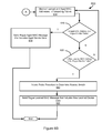
- FIG. 9 depicts a flowchart of an example of a probe procedure to determine a nearest switch to a rogue device in a backhaul of a network.
- FIGS. 10A and 10B depict a flowchart of an example of a method for mitigating a rogue device managed through a backhaul of a network.
- FIG. 11 depicts a flowchart of an example of a method for managing rogue APs that are determined to be valid devices or are Out-Of-Net using a backhaul of a network.
- FIG. 12 depicts a flowchart of an example of a method for managing rogue client devices that are determined to be valid devices or are Out-Of-Net using a backhaul of a network.
- FIG. 1 depicts a diagram 100 of an example of a system for managing rogue devices coupled to a network through a backhaul of the network.
- the example system shown in FIG. 1 includes a computer-readable medium 102 , switches 104 - 1 . . . 104 - n hereinafter collectively referred to as “switches 104 ,” a rogue access point 106 hereinafter referred to as “AP,” a rogue client device 108 , a detector access point 110 , and a network backhaul rogue device management system 112 .
- the rogue client device 108 is coupled to the rogue AP 106 and the rogue AP 106 , the switches 104 , the detector access point 110 and the network backhaul rogue device management system are coupled to each other through the computer-readable medium 102 .
- a “computer-readable medium” is intended to include all mediums that are statutory (e.g., in the United States, under 35 U.S.C. 101), and to specifically exclude all mediums that are non-statutory in nature to the extent that the exclusion is necessary for a claim that includes the computer-readable medium to be valid.
- Known statutory computer-readable mediums include hardware (e.g., registers, random access memory (RAM), non-volatile (NV) storage, to name a few), but may or may not be limited to hardware.
- the computer-readable medium 102 is intended to represent a variety of potentially applicable technologies.
- the computer-readable medium 102 can be used to form a network or part of a network.
- the computer-readable medium 102 can include a bus or other data conduit or plane.
- the computer-readable medium 102 can include a network.
- the network can be an applicable communications network, such as the Internet or an infrastructure network.
- the term “Internet” as used in this paper refers to a network of networks that use certain protocols, such as the TCP/IP protocol, and possibly other protocols, such as the hypertext transfer protocol (HTTP) for hypertext markup language (HTML) documents that make up the World Wide Web (“the web”).
- HTTP hypertext transfer protocol
- a network can include, for example, a wide area network (WAN), metropolitan area network (MAN), campus area network (CAN), or local area network (LAN), but the network could at least theoretically be of an applicable size or characterized in some other fashion (e.g., personal area network (PAN) or home area network (HAN), to name a couple of alternatives).
- PAN personal area network
- HAN home area network
- Networks can include enterprise private networks and virtual private networks (collectively, private networks). As the name suggests, private networks are under the control of a single entity. Private networks can include a head office and optional regional offices (collectively, offices). Many offices enable remote users to connect to the private network offices via some other network, such as the Internet.
- FIG. 1 is intended to illustrate a computer-readable medium 102 that may or may not include more than one private network.
- the computer-readable medium 102 , the rogue AP 106 , the rogue client device 108 , the detector access point 110 , the network backhaul rogue device management system 112 and other systems, or devices described in this paper can be implemented as a computer system or parts of a computer system or a plurality of computer systems.
- a computer system, as used in this paper, is intended to be construed broadly and can include or be implemented as a specific purpose computer system for carrying out the functionalities described in this paper.
- a computer system will include a processor, memory, non-volatile storage, and an interface.
- a typical computer system will usually include at least a processor, memory, and a device (e.g., a bus) coupling the memory to the processor.
- the processor can be, for example, a general-purpose central processing unit (CPU), such as a microprocessor, or a special-purpose processor, such as a microcontroller.
- CPU general-purpose central processing unit
- microcontroller such as
- the memory can include, by way of example but not limitation, random access memory (RAM), such as dynamic RAM (DRAM) and static RAM (SRAM).
- RAM random access memory
- DRAM dynamic RAM
- SRAM static RAM
- the memory can be local, remote, or distributed.
- the bus can also couple the processor to non-volatile storage.
- the non-volatile storage is often a magnetic floppy or hard disk, a magnetic-optical disk, an optical disk, a read-only memory (ROM), such as a CD-ROM, EPROM, or EEPROM, a magnetic or optical card, or another form of storage for large amounts of data. Some of this data is often written, by a direct memory access process, into memory during execution of software on the computer system.
- the non-volatile storage can be local, remote, or distributed.
- the non-volatile storage is optional because systems can be created with all applicable data available in memory.
- Software is typically stored in the non-volatile storage. Indeed, for large programs, it may not even be possible to store the entire program in the memory. Nevertheless, it should be understood that for software to run, if necessary, it is moved to a computer-readable location appropriate for processing, and for illustrative purposes, that location is referred to as the memory in this paper. Even when software is moved to the memory for execution, the processor will typically make use of hardware registers to store values associated with the software, and local cache that, ideally, serves to speed up execution.
- a software program is assumed to be stored at an applicable known or convenient location (from non-volatile storage to hardware registers) when the software program is referred to as “implemented in a computer-readable storage medium.”
- a processor is considered to be “configured to execute a program” when at least one value associated with the program is stored in a register readable by the processor.
- a computer system can be controlled by operating system software, which is a software program that includes a file management system, such as a disk operating system.
- operating system software is a software program that includes a file management system, such as a disk operating system.
- file management system is typically stored in the non-volatile storage and causes the processor to execute the various acts required by the operating system to input and output data and to store data in the memory, including storing files on the non-volatile storage.
- the bus can also couple the processor to the interface.
- the interface can include one or more input and/or output (I/O) devices.
- the I/O devices can include, by way of example but not limitation, a keyboard, a mouse or other pointing device, disk drives, printers, a scanner, and other I/O devices, including a display device.
- the display device can include, by way of example but not limitation, a cathode ray tube (CRT), liquid crystal display (LCD), or some other applicable known or convenient display device.
- the interface can include one or more of a modem or network interface. It will be appreciated that a modem or network interface can be considered to be part of the computer system.
- the interface can include an analog modem, isdn modem, cable modem, token ring interface, satellite transmission interface (e.g. “direct PC”), or other interfaces for coupling a computer system to other computer systems. Interfaces enable computer systems and other devices to be coupled together in a network.
- the computer systems can be compatible with or implemented as part of or through a cloud-based computing system.
- a cloud-based computing system is a system that provides virtualized computing resources, software and/or information to client devices.
- the computing resources, software and/or information can be virtualized by maintaining centralized services and resources that the edge devices can access over a communication interface, such as a network.
- Cloud may be a marketing term and for the purposes of this paper can include any of the networks described herein.
- the cloud-based computing system can involve a subscription for services or use a utility pricing model. Users can access the protocols of the cloud-based computing system through a web browser or other container application located on their client device.
- a computer system can be implemented as an engine, as part of an engine or through multiple engines.
- an engine includes at least two components: 1) a dedicated or shared processor and 2) hardware, firmware, and/or software modules that are executed by the processor.
- an engine can be centralized or its functionality distributed.
- An engine can be a specific purpose engine that includes specific purpose hardware, firmware, or software embodied in a computer-readable medium for execution by the processor.
- the processor transforms data into new data using implemented data structures and methods, such as is described with reference to the FIGs. in this paper.
- the engines described in this paper, or the engines through which the systems and devices described in this paper can be implemented, can be cloud-based engines.
- a cloud-based engine is an engine that can run applications and/or functionalities using a cloud-based computing system. All or portions of the applications and/or functionalities can be distributed across multiple computing devices, and need not be restricted to only one computing device.
- the cloud-based engines can execute functionalities and/or modules that end users access through a web browser or container application without having the functionalities and/or modules installed locally on the end-users' computing devices.
- datastores are intended to include repositories having any applicable organization of data, including tables, comma-separated values (CSV) files, traditional databases (e.g., SQL), or other applicable known or convenient organizational formats.
- Datastores can be implemented, for example, as software embodied in a physical computer-readable medium on a general- or specific-purpose machine, in firmware, in hardware, in a combination thereof, or in an applicable known or convenient device or system.
- Datastore-associated components such as database interfaces, can be considered “part of” a datastore, part of some other system component, or a combination thereof, though the physical location and other characteristics of datastore-associated components is not critical for an understanding of the techniques described in this paper.
- Datastores can include data structures.
- a data structure is associated with a particular way of storing and organizing data in a computer so that it can be used efficiently within a given context.
- Data structures are generally based on the ability of a computer to fetch and store data at any place in its memory, specified by an address, a bit string that can be itself stored in memory and manipulated by the program.
- Some data structures are based on computing the addresses of data items with arithmetic operations; while other data structures are based on storing addresses of data items within the structure itself.
- Many data structures use both principles, sometimes combined in non-trivial ways.
- the implementation of a data structure usually entails writing a set of procedures that create and manipulate instances of that structure.
- the datastores, described in this paper can be cloud-based datastores.
- a cloud-based datastore is a datastore that is compatible with cloud-based computing systems and engines.
- the client device 104 is an applicable device that functions to send data to and receive data from a network.
- the client device 104 can send and receive data through a network device that is part of a network.
- the client device 104 can be a thin client device or an ultra-thin client device.
- Data sent and receive by the client device 104 can be used in executing applications, e.g. a web browser or Apple FACETIME®, on the client device 104 .
- the switches 104 function to transmit data and route data as part of a network. In transmitting and routing data as part of a network, the switches 104 form at least part of a backhaul of the network. The switches 104 can function to transmit data to and from access points and client devices coupled to the access points. Data transmitted by the switches 104 can be used in providing services to a client device through a network.
- the rogue AP 106 functions to transmit data between a client device and a network. In transmitting data between a client device and a network, the rogue AP 106 can couple the client device to the network. The rogue AP 106 can functions as a router by transmitting data between multiple client devices coupled to the rogue AP 106 . The rogue AP 106 can be a rogue device. The rogue AP can be a rogue device because it is not authorized to send and receive data through a network.
- the rogue client device 108 functions to send and receive data through a network.
- the rogue client device 108 is a rogue device.
- the rogue client device 108 can be a rogue device because it is not authorized to send and receive data through a network or is authorized to send and receive data through a network but is coupled to a rogue device.
- the rogue client device 108 includes a station and is coupled to the rogue AP 106 through a wireless connection.
- a station can be referred to as a device with a media access control (MAC) address and a physical layer (PHY) interface to a wireless medium that complies with the IEEE 802.11 standard.
- the network devices 106 and 108 can be referred to as stations, if applicable.
- IEEE 802.11a-1999, IEEE 802.11b-1999, IEEE 802.11g-2003, IEEE 802.11-2007, and IEEE 802.11n TGn Draft 8.0 (2009) are incorporated by reference.
- Wi-Fi is a non-technical description that is generally correlated with the IEEE 802.11 standards, as well as Wi-Fi Protected Access (WPA) and WPA2 security standards, and the Extensible Authentication Protocol (EAP) standard.
- WPA Wi-Fi Protected Access
- EAP Extensible Authentication Protocol
- a station may comply with a different standard than Wi-Fi or IEEE 802.11, may be referred to as something other than a “station,” and may have different interfaces to a wireless or other medium.
- applicable devices, systems and engines described in this paper may or may not be IEEE 802 standards compatible or IEEE 802 standards-compliant.
- IEEE 802 standards-compatible or IEEE 802 standards-compliant complies with at least some of one or more of the incorporated documents' requirements and/or recommendations, or requirements and/or recommendations from earlier drafts of the documents, and includes Wi-Fi systems.
- the detector access point 110 functions to detect a rogue device.
- a rogue device detected by the detector access point 110 can be either a rogue AP or a rogue client device.
- the detector access point 110 can detect a rogue device according to an applicable technique for detecting a rogue device. For example, the detector access point 110 can detect a rogue device if the rogue device does not conform with standards specific to devices coupled to a network.
- the detector access point 110 can detect a rogue device if unusual amounts of data are transmitted to the rogue device when compared to amounts of data transmitted to other devices in the network, or data is transmitted to the rogue device in unusual patterns when compared to patterns by which data is transmitted to other devices in the network.
- the detector access point 110 can form part of a mesh network with a rogue AP that it detects as a rogue device.
- the network backhaul rogue device management system 112 functions to manage detected rogue devices using a backhaul of a network.
- the network backhaul rogue device management system 112 can receive a detected rogue device message from the detector access point that identifies a detected rogue device. Further in managing rogue devices, the network backhaul rogue device management system 112 can generate a rogue device message to the switches 104 that includes an identification of a detected rogue device.
- the rogue device message is a rogue device multicast (or broadcast) message.
- the rogue device message is a rogue device unicast message.
- the rogue device message includes a plurality of unicast or multicast messages sent for the purpose of accomplishing one or more of the goals described in this paper.
- the network backhaul rogue device management system 112 can receive messages from the switches 104 when switches detect a rogue device identified in a rogue device message.
- the network backhaul rogue device management system 112 can receive a rogue new learned MAC message that includes new learned device data if a newly learned MAC address in a forwarding table of a switch matches an identification of a rogue device included in a rogue device message.
- the network backhaul rogue device management system 112 can receive a rogue aged MAC message that includes aged device data if a MAC address aged out of a forwarding table of a switch matches an identification of a rogue device included in a rogue device message.
- the network backhaul rogue device management system 112 can use new learned device data included in a rogue new learned MAC message and aged device data included in a rogue aged MAC message, to determine if a rogue device is In-Net or Out-Of-Net.
- the network backhaul rogue device management system 112 can perform mitigation of a rogue device through a backhaul of a network. In performing mitigation of a rogue device, the network backhaul rogue device management system 112 can determine an action for mitigation of a rogue device. For example the network backhaul rogue device management system 112 can determine to add a rogue device to unauthorized list. In another example, the network backhaul rogue device management system 112 can determined to block all traffic on a port of a switch that a rogue device is coupled to the switch through.
- the network backhaul rogue device management system 112 can generate and send an unauthorized list mitigation message or a block port mitigation message based on a determined action for mitigation of a rogue device. Switches can perform mitigation of a rogue device using an unauthorized list mitigation message and a block port mitigation message received from the network backhaul rogue device management system 112 .
- FIG. 2 depicts a diagram 200 of an example of a system for managing rogue devices through a backhaul of a network.
- the example system shown in FIG. 2 includes a computer-readable medium 202 , switches 204 - 1 and 204 - 2 , hereinafter collectively referred to as “switches 204 ,” and a network backhaul rogue device management system 206 .
- the switches 204 and the network backhaul rogue device management system 206 are coupled to each other through the computer-readable medium.
- the switches 204 function according to applicable switches in a backhaul of a network for managing rogue devices, such as switches described in this paper, for managing a rouge device through a backhaul of a network.
- the switches function to send aged MAC address messages and new learned MAC address messages.
- the network backhaul rogue device management system 206 functions according to an applicable system for managing rogue devices through a backhaul of a network, such as the network backhaul rogue device management systems described in this paper.
- the network backhaul rogue device management system 206 can function to manage rogue APs associated with new learned device data received as part of a rogue learned MAC message received from the switches 204 .
- the network backhaul rogue device management system 206 can determine a rogue AP associated with the new learned device data.
- the network backhaul rogue device management system can determine a rogue AP associated with the learned device from new learned device data included in a learned MAC message or from learned device data included in a new learned device data include in a learned aged MAC message and a rogue AP table or a rogue learning table.
- the network backhaul rogue device management system 206 functions to update a status of a rogue AP determined as In-Net.
- the network backhaul rogue device management system 206 can receive a rogue leaned MAC message that includes new learned device data from switches in a backhaul of a network.
- the network backhaul rogue device management system 206 functions to perform mitigation of a rogue AP that is determined to be In-Net. In performing mitigation of a rogue AP that is determined to be In-Net, the network backhaul rogue device management system 206 can function to send a mitigation message that is used in performing mitigation of a rogue device.
- the network backhaul rogue device management system 206 functions to receive a rogue aged MAC message that includes aged device data.
- Aged device data included in a rogue aged MAC message received by the network backhaul rogue device management system 206 can include a MAC address of a rogue device that is aged out of a forward learning tale and a VLAN ID of a rogue device with a MAC address that is aged out a forwarding table.
- the network backhaul rogue device management system 206 functions to determine a rogue AP associated with aged device data included in a rogue aged MAC message.
- the network backhaul rogue device management system 206 functions to update a status of a rogue AP associated with a rogue device that is aged out of a forward learning table as Out-Of-Net. In a specific implementation, the network backhaul rogue device management system 206 functions to update a status of a rogue AP associated with a rogue device that is aged out of a forward learning table as In-Net if other devices associated with the rogue AP are newly learned by forwarding tables, and therefore in the rogue learning table.
- the network backhaul rogue device management system 206 functions to perform mitigation, at least in part of a rogue AP associated with a rogue device that is aged out of a forward learning table. In performing mitigation of a rogue AP associated with a rogue device that is aged out of a forward learning table, the network backhaul rogue device management system 206 can function to send a mitigation message that is used in performing mitigation of a rogue device.
- the network backhaul rogue device management system 206 includes a rogue AP table management engine 208 , a rogue AP table datastore 210 , a rogue learning table management engine 212 , a rogue learning table datastore 214 , a rogue device status determination engine 216 , and a rogue device message engine.
- the rogue AP table management engine 208 functions to manage a rogue AP table stored in the rogue AP table datastore 210 .
- a rogue AP table stored in the rogue AP table datastore 210 can include an identification, e.g. a MAC address, of a rogue AP and an identification, e.g. a MAC address, of rogue client devices that are coupled to the rogue AP.
- the rogue AP table management engine 208 functions to determine whether a rogue device detected by an applicable system or device for detecting a rogue device, is in a rogue AP table.
- the rogue AP table management engine 208 can determined whether a rogue device is in a rogue AP table after receiving a detected rogue device message that includes an identification of the rogue device, e.g. a MAC address of the rogue device.
- the AP table management engine 208 can determine whether the rogue AP table has an entry that includes an identification of the rogue device.
- the rogue AP table management engine 208 functions to add a MAC address of a rogue device to a rogue AP table.
- the rogue AP table management engine 208 can create an entry in a rogue AP table that includes the MAC address of the rogue device.
- the rogue AP table management engine 208 can add a MAC address of a rogue device into a rogue AP table, if it determines that the rogue device is not in the rogue AP table.
- the rogue AP table management engine 208 functions to determine rogue client devices associated with a rogue AP. In determining rogue client devices associated with a rogue AP, the rogue AP table management engine 208 can look up a MAC address of a rogue AP in a rogue AP table, to determine if rogue client devices are included in entries with the rogue AP. The rogue AP table management engine 208 can determine rogue client devices associated with a rogue AP, after it is determined that a rogue AP is a valid device. The rogue AP table management engine 208 can also determine a rogue client device associated with a rogue AP, after it is determined that the rogue AP is Out-Of-Net.
- the rogue AP table management engine 208 functions to remove entries of a rogue AP and rogue client devices associated with the rogue AP from a rogue AP table.
- the rogue AP table management engine 208 can remove entries of a rogue AP and rogue client devices associated with the rogue AP from a rogue AP table after it is determined that the rogue AP is a valid device.
- the rogue AP table management engine 208 can remove entries of a rogue AP and rogue client devices associated with the rogue AP from a rogue AP table after it is determined that the rogue AP is Out-Of-Net.
- the rogue AP table management engine 208 functions to remove entries of a rogue client device from a rogue AP table.
- the rogue AP table management engine 208 can remove entries of a rogue client device from a rogue AP table, if it is determined that the rogue client device is a valid device.
- the rogue AP table management engine 208 can remove entries of a rogue client device from a rogue AP table, if it is determined that the rogue client device is Out-Of-Net.
- the rogue learning table management engine 212 functions to manage a rogue learning table stored in the rogue learning table datastore 214 .
- a rogue learning table stored in the rogue learning table datastore 214 can include a MAC address, including a learned MAC address, of a rogue device, including both rogue APs and rogue client devices.
- a rogue learning table stored in the rogue learning table datastore 214 can also include a VLAN ID of a rogue device, and a MAC address of a nearest switch to a rogue device.
- the rogue learning table management engine 212 functions to determine whether an entry in a rogue learning table matches new learned device data included in a rogue learned MAC message. In determining whether an entry in a rogue learning table matches new learned device data, the rogue learning table management engine 212 can determine whether an identification of a rogue device, e.g. a MAC address of the rogue device, included as part of new learned device data in a rogue learned MAC message, is in an entry in the rogue learning table.
- a rogue device e.g. a MAC address of the rogue device
- the rogue learning table management engine 212 functions to add new learned device data included in a rogue learned MAC message to a rogue learning table.
- the rogue learning table management engine 212 can add a learned MAC address of a rogue device, a VLAN ID of the rogue device, and a MAC address of a nearest switch or switches to the rogue device to a rogue learning table.
- the rogue learning table management engine 212 can add new learned device data included in a rogue learned MAC message to a rogue learning table if it is determined that no entries in the rogue learning table match the new learned device data.
- the rogue learning table management engine 212 functions to determine whether an entry in a rogue learning table matches aged device data included in a rogue aged MAC message. In determining whether an entry in a rogue learning table matches aged device data, the rogue learning table management engine 212 can determine whether an identification of a rogue device, e.g. a MAC address of the rogue device, included as part of aged device data in a rogue aged MAC message, is in an entry in the rogue learning table.
- a rogue device e.g. a MAC address of the rogue device
- the rogue learning table management engine 212 functions to remove entries that are matched to aged device data included in a rogue aged MAC message from a rogue learning table. For example if an entry in a rogue learning table includes a MAC address of a rogue device, included as aged device data in a rogue aged MAC message, then the rogue learning table management engine 212 can remove entries in the rogue learning table that include the MAC address of the rogue device.
- the rogue learning table management engine 212 functions to remove entries of a rogue AP and rogue client devices associated with the rogue AP from a rogue learning table.
- the rogue learning table management engine 212 can remove entries of a rogue AP and rogue client devices associated with the rogue AP from a rogue learning table after it is determined that the rogue AP is a valid device.
- the rogue learning table management engine 212 can remove entries of a rogue AP and rogue client devices associated with the rogue AP from a rogue learning table after it is determined that the rogue AP is Out-Of-Net.
- the rogue learning table management engine 212 functions to remove entries of a rogue client device from a rogue learning table.
- the rogue learning table management engine 212 can remove entries of a rogue client device from a rogue learning table, if it is determined that the rogue client device is a valid device.
- the rogue learning table management engine 212 can remove entries of a rogue client device from a rogue learning table, if it is determined that the rogue client device is Out-Of-Net.
- the rogue device status determination engine 216 functions to determine a status of a rogue device. Depending upon implementation-specific or other considerations, the rogue device status determination engine 216 can determine a status of a rogue device that is either a rogue AP or a rogue client device. In determining status of a rogue device, the rogue device status determination engine 216 can determine that the rogue device is Out-Of-Net. For example, the rogue device status determination engine 216 can determine that a rogue device is Out-Of-Net if a status of the rogue device is updated to Out-Of-Net.
- a status of a rogue device can be updated to Out-Of-Net, if the rogue device is the subject of aged device data included in a rogue aged MAC message, and it is determined that other new learned rogue devices are not associated with the rogue device.
- the rogue device status determination engine 216 can determine that a rogue device is In-Net if the status of the rogue device does not change from In-Net or is changed to In-Net.
- a status of a rogue device can be In-Net, if the rogue device is the subject of aged device data included in a rogue aged MAC message, and it is determined that other new learned rogue devices are associated with the rogue device.
- the rogue device status determination engine 216 can determine that the rogue device is a valid device.
- the rogue device status determination engine 216 can determine that a rogue device is a valid device if either or both input is received from a network administrator indicating that the rogue device is a valid device, or if it determines that the rogue device conforms with network policies for a network.
- the rogue device message engine 218 functions to generate and send messages used in managing rogue devices through a backhaul of a network.
- the rogue device message engine 218 can generate and send a rogue device message.
- a rogue device message generated and sent by the rogue device message engine 218 can include an identification, e.g. a MAC address, of a rogue device detected by an applicable system or device, such as a detector access point described in this paper.
- the rogue device message engine 218 can send a rogue device message to switches 204 in a backhaul of a network.
- the rogue device message engine 218 can generate and send a rogue update message.
- a rogue update message generated and sent by the rogue device message engine 218 can include rogue removal data.
- Rogue removal data included in a rogue update message can list an identification, e.g. a MAC address, of rogue devices that are either valid network devices or are determined to be Out-Of-Net.
- Rogue removal data included in a rogue update message can include a list of rogue APs and rogue client devices coupled to the rogue AP that are determined to be valid network devices or are determined to be Out-Of-Net.
- FIG. 3 depicts a diagram 300 of an example of a system for managing rogue devices using an originator switch in a backhaul of a network.
- the example system shown in FIG. 3 includes a computer-readable medium 302 , a network backhaul rogue device management system 304 , and an originator switch 306 .
- the network backhaul rogue device management system 304 and the originator switch 306 are coupled to each other through the computer-readable medium 302 .
- the network backhaul rogue device management system 304 functions according to an applicable system for managing rogue devices in a network through a backhaul of the network, such as network backhaul rogue device management systems described in this paper.
- the network backhaul rogue device management system 304 can send rogue device messages that include an identification of a detected rogue device in a network.
- the network backhaul rogue device management system 304 can send rogue update messages that include rogue removal data.
- Rogue removal data included in rogue update messages can include an identification of rogue devices that are either determined to be valid devices or are determined to be Out-Of-Net.
- the originator switch functions according to an applicable switch in a backhaul of a network used in managing rogue devices in the network, such as the switches described in this paper.
- An originator switch as used in this paper, is a switch in a backhaul of a network that newly learns a MAC address of a rogue device, or ages a MAC address of a rogue device out of a forwarding table of the switch.
- the originator switch functions to receive messages from the network backhaul rogue device management system that are used in managing rogue devices in a network. For example, the originator switch can receive rogue device messages, and rogue update messages.
- the originator switch 306 includes a forwarding table management engine 308 , a forwarding table datastore 310 , a rogue monitor table management engine 312 , a rogue monitor table datastore 314 , an originator switch probe management system 316 , and a rogue learned and aged MAC message engine 318 .
- the forwarding table management engine 308 functions to manage a forwarding table for the originator switch stored in the forwarding table datastore 310 . In managing a forwarding table, the forwarding table management engine 308 can add and delete entries from a forwarding table that include MAC addresses of devices, including rogue devices, in a network.
- the forwarding table management engine 308 functions to flush entries from a forwarding table in response to a rogue device message received from the network backhaul rogue device management system 304 . For example, if a rogue device message includes an identification of a rogue device, e.g. a MAC address of the rogue device, then the forwarding table management engine 308 can remove entries in the forwarding table that include the identification of the rogue device.
- a rogue device message includes an identification of a rogue device, e.g. a MAC address of the rogue device
- the forwarding table management engine 308 functions to remove entries from a forwarding table in response to a rogue update message received from the network backhaul rogue device management system 304 . For example if rogue removal data included in a rogue update message specifies identifications of rogue devices that are either determined to be valid devices or are determined to no longer be In-Net, i.e. are Out-Of-Net, then the forwarding table management engine 308 can remove entries in a forwarding table that contain identification of the rogue devices included in the rogue removal data.
- the rogue monitor table management engine 312 functions to manage a rogue monitor table.
- the rogue monitor table management engine 312 can monitor a rogue monitor table that is stored in the rogue monitor table datastore 314 .
- the rogue monitor table management engine 312 and the rogue monitor table datastore 314 can be implemented as a corresponding cloud-based engine and cloud-based datastore.
- a rogue monitor table managed by the rogue monitor table management engine 312 and stored in the rogue monitor table datastore 314 can include entries that include an identification of a rogue device, e.g.
- the rogue monitor table management engine 312 can add and delete entries from a rogue monitor table stored in the rogue monitor table datastore 314 .
- the rogue monitor table management engine 312 functions to add entries into a rogue monitor table in response to a rogue device message received from the network backhaul rogue device management system 304 . For example, if a rogue device message includes an identification of a rogue device, e.g. a MAC address of the rogue device, then the rogue monitor table management engine 312 can add entries in a rogue monitor table that include the identification of the rogue device.
- the rogue monitor table management engine 312 functions to remove entries from a rogue monitor table in response to a rogue update message received from the network backhaul rogue device management system 304 .
- a rogue update message received from the network backhaul rogue device management system 304 .
- the rogue monitor table management engine 312 can remove entries in a rogue monitor table that contain identification of the rogue devices included in the rogue removal data.
- the forwarding table management engine 308 functions to monitor learned and aged MAC addresses in a forwarding table stored in the forwarding table datastore 310 .
- monitoring learned and aged MAC addresses in a forwarding table can use a rogue monitor table stored in the rogue monitor table datastore 314 .
- the forwarding table management engine 308 can determine whether a new learned MAC address or a MAC address aged out of a forwarding table are included in a rogue monitor table.
- the originator switch probe management system 316 functions to initiate a probe procedure to determine one or a plurality of nearest switches to a rogue device with a MAC address that is newly learned in a forwarding table and is in a rogue monitor table, as determined by the forwarding table management engine 308 .
- the originator switch probe management system 316 can generate a probe message that includes an initial hop number.
- the originator switch probe management system 316 can send a probe message with an initial hop number to one or a plurality of next switches in a backhaul of a network.
- the originator switch probe management system 316 can send a probe message to a plurality of next switches that form different branches in a backhaul of a network.
- the rogue learned and aged MAC message engine 318 functions to generate and send a rogue aged MAC message to the network backhaul rogue device management system 304 .
- the rogue learned and aged MAC message engine 318 can generate a rogue aged MAC message if the forwarding table management engine 308 determines that a MAC address aged out of a forwarding table is in a rogue monitor table.
- a rogue aged MAC message generated by the rogue learned and aged MAC message engine 318 can include aged device data.
- Aged device data included in an aged MAC message can include the aged MAC address.
- Aged device data can also include a VLAN ID of a rogue device that has the aged MAC address or a switch with a corresponding forwarding table from which the MAC address is aged.
- New learned device data included in a new learned MAC message can include the new learned MAC address.
- New learned device data can also include a VLAN ID of a rogue device that has the new learned MAC address or a switch with a corresponding forwarding table from which the MAC address is aged.
- new learned device data can also include one or a plurality of nearest switches to a rogue device with the new learned MAC address determined by the forwarding table management engine 308 to be in a rogue monitor table.
- the rogue learned and aged MAC message engine 318 functions to generate and send a rogue learned MAC message to the network backhaul rogue device management system 304 .
- the rogue learned and aged MAC message engine 318 can generate a rogue learned MAC message if the forwarding table management engine 308 determines that a MAC address newly learned in a forwarding table is in a rogue monitor table.
- a rogue learned MAC message generated by the rogue learned and aged MAC message engine 318 can include new learned device data.
- Aged device data included in an aged MAC message can include the aged MAC address.
- Aged device data can also include a VLAN ID of a rogue device that has the aged MAC address or a switch with a corresponding forwarding table from which the MAC address is aged.
- FIG. 4 depicts a diagram 400 of an example of a system for determining a nearest switch to a rogue device.
- the example system shown in FIG. 4 includes a computer-readable medium 402 , an originator switch probe management system 404 , and a switch probe management system 406 .
- the originator switch probe management system 404 and the switch probe management system are coupled to each other through the computer-readable medium 402 .
- the originator switch probe management system 404 functions according to an applicable system for determining a nearest switch to a rogue device.
- the originator switch probe management system 404 can be implanted on an originator switch.
- the originator switch probe management system can generate and send a probe message with an initial hop number to the switch probe management system 406 .
- the switch probe management system 406 functions to generate a probe response to a received probe message.
- the switch probe management system 406 also functions to forward a received probe message to a next switch in a backhaul of a network.
- the originator switch probe management system 404 includes a probe message generation engine 408 and a probe datastore 410 .
- the probe message generation engine 408 functions to generate and send a probe message.
- the probe message generation engine 406 can generate and send a probe message after it is determined at an originator switch that a new learned MAC address in a forwarding table of the originator switch is in a rogue monitor table.
- a probe message generated by the probe message generation engine 408 can include a new learned MAC address that is determined to be in a rogue monitor table.
- a probe message generated by the probe message generation engine 408 can also include an initial hop number.
- the probe datastore 410 functions to store probe data.
- Probe data stored in the probe datastore 410 can include an initial hop number that is sent with a probe message that is sent by the probe message generation engine.
- the switch probe management system 406 includes a forwarding table management engine 414 , a probe response generation engine 414 , and a probe message forwarding engine 416 .
- the forwarding table management engine 414 functions according to an applicable engine for managing a forwarding table of a switch, such as a forwarding table management engine described in this paper.
- the forwarding table management engine 414 can determine whether a new learned MAC address included in a probe message received from the originator switch probe management system is included in a forwarding table of a switch of which the switch probe management system is associated.
- the probe response generation engine 414 functions to generate and send a probe response back to the originator switch probe management system 404 .
- the probe response generation engine 414 can generate and send a probe response if it is determined by the forwarding table management engine 412 that a new learned MAC address included in the probe message is in a forwarding table at the switch, as determined by the switch probe management system 406 .
- a probe response generated by the probe response generation engine can include an increased hop number that the probe response generation engine increases and an identification of a switch associated with the switch probe management system 406 .
- a probe response generated by the probe response generation engine 412 and sent to the originator switch probe management system 404 can be stored as probe data in the probe datastore 410 .
- the probe response generation engine 414 functions to increase a hop number in a probe response.
- the probe response generation engine 414 can increase a hop number in a probe response if it is determined by the forwarding table management engine 412 that a new learned MAC address included in the probe message is in a forwarding table at the switch, as determined by the switch probe management system 406 .
- the probe message forwarding engine 416 functions to forward a probe message to a next switch.
- the probe message forwarding engine 416 can forward a probe message to a next switch as a layer 2 package.
- the probe message forwarding engine 416 can forward a probe message that includes an increased hop number increased by the probe response generation engine 414 .
- the probe message forwarding engine 416 can forward a probe message that does not include a hop number that has been increased by the probe response generation engine 414 .
- the nearest switch determination engine 418 determines a nearest switch based on whether probe responses are received and probe responses that are received. In determining a nearest switch to a rogue device, the nearest switch determination engine 418 determines if any probe responses are received and included as probe data stored in the probe datastore 410 . If it is determined that no probe responses are received, then the nearest switch determination engine 418 can determine that an originator switch is the nearest switch. Further depending upon implementation-specific or other considerations, if probe responses are received, the nearest switch determination engine 418 can determine that a switch that sent a probe response with the highest increased hop number is a nearest switch to a rogue device.
- FIG. 5 depicts a diagram 500 of an example of a system for managing mitigation of a rogue device through a backhaul of a network.
- the example system shown in FIG. 5 includes a computer-readable medium 502 , a network backhaul rogue device management system 504 , and a nearest switch 506 .
- the network backhaul rogue device management system 504 and the nearest switch 506 are coupled to each other through the computer-readable medium 502 .
- the network backhaul rogue device management system 504 can function according to an applicable system for managing rogue devices through a backhaul of a network, such as the network backhaul rogue device management systems described in this paper.
- the network backhaul rogue device management system 504 can send rogue device messages that include an identification of a detected rogue device in a network.
- the network backhaul rogue device management system 504 can send rogue update messages that include rogue removal data.
- Rogue removal data included in rogue update messages can include an identification of rogue devices that are either determined to be valid devices or are determined to be Out-Of-Net.
- the nearest switch 506 functions according to an applicable switch for managing rogue devices through a backhaul of a network.
- the nearest switch 506 can be a nearest switch or one of a plurality of nearest switches to a rogue device on which mitigation is performed.
- the network backhaul rogue device management system 504 includes an action mode determination engine 508 , a mitigation message generation engine 510 , a rogue device type determination engine 512 , and a nearest switch monitoring engine 514 .
- the action mode determination engine 508 functions to determine an action mode for mitigation of a rogue device.
- the action mode determination engine 508 can determine an action mode for mitigation of a rogue device from policies of a network. For example, if network policies specify to add a rogue device to an unauthorized list, then the action mode determination engine 508 can determine that an action mode for mitigation is adding the rogue device to the unauthorized list.
- the action mode determination engine 508 can also determine an action mode for mitigation of a rogue device can by querying a network administrator for a specific action mode.
- the mitigation message generation engine 510 can generate and send a mitigation message to the nearest switch.
- a mitigation message generated and sent by the mitigation message generation engine 510 can be an unauthorized list mitigation message.
- the mitigation message generation engine 510 can generate and send an unauthorized list mitigation message to the nearest switch 506 if the action mode determination engine 508 determines that an action mode is to add a rogue device to an unauthorized list.
- An unauthorized list mitigation message generated and sent by the mitigation message generation engine 510 can identify that the determined action mode for mitigation of the rogue device is adding the rogue device to the unauthorized list.
- a mitigation message generated and sent by the mitigation message generation engine 510 can also include a MAC address of a rogue device, a BSS ID of the rogue device, and a VLAN ID of the rogue device. Further depending upon implementation-specific or other considerations, a mitigation message generated and sent by the mitigation message generation engine 510 can be a block port mitigation message. A block port mitigation message generated and sent by the mitigation message generation engine 510 can identify that the determined action mode for mitigation of the rogue device is to block the port through which the rogue device is coupled to the nearest switch. A block portion mitigation message generated and sent by the mitigation message generation engine 510 can also include a MAC address of a rogue device, a BSS ID of the rogue device, and a VLAN ID of the rogue device.
- the rogue device type determination engine 512 functions to determine a device type of a rogue device. In determining a device type of a rogue device, the device type determination engine 512 can determine whether a rogue device is a rogue AP or a rogue client device. The rogue device type determination engine 512 can determine whether a rogue device is a rogue client or a rogue AP by looking up the MAC address of the rogue device in a rogue AP table.
- the mitigation message generation engine 510 can generate and send an unauthorized list mitigation message for the rogue device to the nearest switch 506 .
- the nearest switch monitoring engine 514 functions to determine if there are multiple nearest switches to a rogue device.
- the nearest switch monitoring engine 514 can determine if there are multiple nearest switches to a rogue device from probe data that indicates the identifications of nearest switches to a rogue device. If the action mode determination engine 508 determines that an action mode for mitigation is to block a port of a switch to which a rogue device is coupled and the nearest switch monitoring engine 514 determines that there are multiple nearest switches to the rogue device, then the mitigation message generation engine 510 .
- the mitigation message generation engine 510 can generate and send a block port mitigation message to the nearest switch 506 .
- the nearest switch 506 includes an unauthorized list management engine 516 , an unauthorized list datastore 518 , a port determination engine 520 , a neighboring device determination engine 522 , a port power determination engine 524 , and a port management engine 526 .
- the unauthorized list management engine 516 functions to manage an unauthorized list stored in the unauthorized list datastore 516 .
- the unauthorized list management engine 516 and the unauthorized list datastore 516 can be implemented as a corresponding cloud-based engine and a cloud-based datastore.
- the unauthorized list management engine 516 can add an identification of a rogue device, e.g. a MAC address of the rogue device, to an unauthorized list stored in the unauthorized list datastore if an unauthorized list mitigation message for the rogue device is received from the network backhaul rogue device management system.
- the port determination engine 520 functions to determine a port on the nearest switch 506 at which the rogue device is coupled to the switch.
- the port determination engine 520 can determine a port on the nearest switch 506 after a block port mitigation message is received at the nearest switch.
- the neighboring device determination engine functions to determine a neighboring device that is coupled to a port of the nearest switch 506 determined by the port determination engine 520 .
- the neighboring device determination engine 522 can determine that a switch is a neighboring device. If a block port mitigation message for a rogue device is received and the neighboring device determination engine determines that a neighboring device is a switch, then the unauthorized list management engine 516 can add the MAC address of the rogue device to an unauthorized list stored in the unauthorized list datastore 518 . Further depending upon implementation-specific or other considerations, the neighboring device determination engine 522 can determine that a rogue device is a neighboring device.
- the port power determination engine 524 determines whether a port determined by the port determination engine 520 is supplying power.
- the port power determination engine 524 can use an applicable mechanism for determining power, to determine whether a port determined by the port determination engine 520 is supplying power. If a block port mitigation message for a rogue device is received and the port power determination engine 524 determines that a port on the nearest switch associated with the rogue device is not supplying power, then the unauthorized list management engine 516 can add the MAC address of the rogue device to an unauthorized list stored in the unauthorized list datastore 518 .
- the port management engine 526 functions to block traffic on a port determined by the port determination engine 520 .
- the port management engine can block all traffic on a port if a block port mitigation message for a rogue device is received, a neighboring device on a port determined by the port determination engine 520 , and it is determined that the port is supplying power, then the port management engine 526 can block all traffic on the port.
- FIGS. 6A and 6B depict a flowchart 600 of an example of a method for monitoring rogue devices in a network through a backhaul of the network.
- the flowchart 600 begins at module 602 where a rogue device is detected.
- a rogue device detected at module 602 can be either a rogue AP or a rogue client device.
- a rogue device can be detected at module 602 by an applicable device for detecting a rogue device.
- a detector that detects a rogue device at module 602 can be an AP that is part of a network, such as a detector access point described in this paper.
- an AP that detects a rogue device at module 602 can be part of a mesh network that includes the detected rogue device.
- a rogue device can be detected at module 602 according to an applicable technique for detecting a rogue device. For example, a rogue device can be detected at module 602 if it does not conform with standards specific to network devices coupled to a network. In another example, a rogue device can be detected at module 602 if unusual amounts of data are transmitted to the rogue device when compared to amounts of data transmitted to other devices in the network, or data is transmitted to the rogue device in unusual patterns when compared to patterns by which data is transmitted to other devices in the network.
- the flowchart 600 continues to decision point 604 , where it is determined whether the rogue device detected at module 602 is in a rogue AP table.
- An applicable system for managing a rogue AP table can determine whether the rogue device detected at module 602 is in the rogue AP table, such as a rogue AP table management engine as described in this paper.
- a rogue AP table can be maintained as a cloud-based datastore, and a rogue AP table management engine can determine whether the rogue device detected at module 602 is in the rogue AP table.
- an applicable system or engine such as a network backhaul rogue device management system or a rogue AP table management engine can determine whether the rogue device is in the rogue AP table in response to a detected rogue device message received from an applicable device for detecting a rogue device, such as a detector access point described in this paper. If it is determined at decision point 604 that the rogue device detected at module 602 is in a rogue AP table, then the flowchart 600 ends.
- a network backhaul rogue device management system or a rogue AP table management engine can determine whether the rogue device is in the rogue AP table in response to a detected rogue device message received from an applicable device for detecting a rogue device, such as a detector access point described in this paper. If it is determined at decision point 604 that the rogue device detected at module 602 is in a rogue AP table, then the flowchart 600 ends.
- a MAC address of the rogue device detected at module 602 is added to the rogue AP table.
- An applicable system for managing a rogue AP table can add a MAC address of the rogue device into the rogue AP table, such as a rogue AP table management engine described in this paper.
- a MAC address of the rogue device that is added to the rogue AP table at module 606 can be included in a detected rogue device message received from an applicable device for detecting a rogue device, such as a detector access point described in this paper.
- the flowchart 600 continues to module 608 , where a rogue device message that includes the MAC address of the rogue device is generated and sent to switches.
- a rogue device message can be generated and sent to switches at module 608 by an applicable system for generating and sending a rogue device message, such as a rogue device message engine described in this paper.
- a rogue device message can be sent at module 608 to switches that form, at least part of, a backhaul of a network.
- a rogue device message can be sent at module 608 to a subset of switches that form a backhaul of a network.
- a rogue device message can be sent to a subset of switches that route traffic, are located around, or are otherwise associated with a detector that detects the rogue device at module 602 .
- the flowchart 600 continues to module 610 , where entries that include the MAC address of the rogue device includes in the rogue device message sent at module 608 are removed from forwarding tables of the switches. Entries of the forwarding tables of the switches that include the MAC address in the rogue device message can be removed by an applicable engine for managing the forwarding tables of the switches, such as forwarding table management engines described in this paper. Depending upon implementation-specific or other considerations, a switch may or may not have to flush entries from a forwarding table that include the MAC address in the rogue device message, based on whether the switch has routed traffic to the rogue device with the MAC address.
- the flowchart 600 continues to module 612 , where the MAC address included in the rogue device message, is added to a rogue monitor table.
- An applicable system for managing a rogue monitor table such as rogue monitor table management engines described in this paper, can add the MAC address included in the rogue device message to the rogue monitor table.
- specific a rogue monitor table can be implemented on each switch in a backhaul of a network that receives the rogue device message, or implemented in a cloud-based datastore that is accessible by the switches to which the rogue device message are sent.
- a single applicable engine such as a rogue monitor table management engine, associated with a particular switch can update the rogue monitor table by adding the MAC address into the rogue monitor table.
- a rogue monitor table management engine associated with a particular switch can update the rogue monitor table by adding the MAC address into the rogue monitor table.
- an entry in the rogue monitor table can be added that includes a learned status field that indicates that the rogue device with the MAC address remains learned, e.g. is still in forwarding tables of the.
- the flowchart 600 continues to module 614 , where learned and aged MAC address in the forwarding tables of switches are monitored.
- Learned and aged MAC addresses in the forwarding tables of switches can be monitored by an applicable engine for managing forwarding tables of switches, such as forwarding table management engines described in this paper.
- learned and aged MAC addresses in forwarding tables of switches can be monitored by a forwarding table management engine that is implemented as a cloud-based engine.
- learned and aged MAC address in forwarding tables of switches can be monitored by forwarding table management engines that are implemented on specific switches that include specific forwarding tables that the forwarding table management engines manages.
- the flowchart 600 continues to decision point 616 where it is determined whether the MAC address included in the rogue device message that is added to the rogue monitor table is aged out of a forwarding table.
- An applicable engine for managing a forwarding table such as a forwarding table management engine described in this paper, can determine whether a MAC address include in the rogue monitor table is aged out of a forwarding table. Specifically, it can be determined whether an entry aged out of a forwarding table includes a MAC address included in an entry in the rogue monitor table.
- the flowchart 600 includes sending an aged MAC message that includes aged device data.
- An aged MAC message that includes aged device data can be sent to a network backhaul rogue device management system.
- a rogue aged MAC message can be sent from a switch that includes a forwarding table from which the MAC address included in the rogue monitor table is aged out.
- a rogue aged MAC message that is generated and sent at module 618 can be generated and sent by an applicable engine for generating and sending a rogue aged MAC message, such as a rogue learned and aged MAC message engine described in this paper.
- a rogue aged MAC message sent at module 618 can include aged device data.
- Aged device data included in an aged MAC message can include the aged MAC address.
- Aged device data can also include a VLAN ID of a rogue device that has the aged MAC address or a switch with a corresponding forwarding table from which the MAC address is aged.
- a learned status field in the rogue monitor table can be updated to indicate that the MAC address has been aged out of the forwarding table of a corresponding switch.
- An applicable engine for managing a forwarding table can determine whether a MAC address include in a rogue monitor table is newly learned in a forwarding table. Specifically, it can be determined whether an entry newly learned in a forwarding table includes a MAC address included in an entry in the rogue monitor table.
- a probe procedure is initiated to determine a nearest switch to a rogue device with a new learned MAC address in a forwarding table.
- An applicable probe procedure for determining a nearest switch such as a probe procedure described in this paper, can be initiated at module 622 .
- a learned status field in the rogue monitor table can be updated to indicate that the MAC address has been newly learned in a forwarding table of a corresponding switch.
- the flowchart 600 continues to module 624 , where a rogue learned MAC address that includes new learned device data of a rogue device of the new learned MAC address is sent.
- a new learned MAC message that includes new learned device data can be sent to a network backhaul rogue device management system.
- a new learned MAC message can be sent from a switch that includes a forwarding table in which the MAC address included in the rogue monitor table is newly learned.
- a new learned MAC message that is generated and sent at module 624 can be generated and sent by an applicable engine for generating and sending a new learned MAC message, such as a rogue learned and aged MAC message engine described in this paper.
- a new learned MAC message sent at module 618 can include new learned device data.
- New learned device data included in a new learned MAC message can include the new learned MAC address.
- New learned device data can also include a VLAN ID of a rogue device that has the new learned MAC address or a switch with a corresponding forwarding table from which the MAC address is aged.
- FIG. 7 depicts a flowchart 700 of an example of a method for managing a rogue device with a MAC address that is newly learned in a backhaul of a network.
- the flowchart 700 begins at module 702 , where a rogue learned MAC message that includes new learned device data is received.
- a rogue learned MAC message that includes new learned device data can be received by an applicable system for managing a rogue device using backhaul of a network, such as a network backhaul rogue device management system described in this paper.
- New learned device data included in a rogue learned MAC message received at module 702 can include a MAC address of a rogue device that is newly learned in a forwarding table.
- New learned device data included in a rogue learned MAC message received at module 702 can also include a VLAN ID of a rogue device with a MAC address that is newly learned in a forwarding table.
- a VLAN ID of a rogue device with a MAC address that is newly learned in a forwarding table can be learned using a probe procedure to determine a nearest switch to the rogue device.
- the flowchart 700 continues to decision point 704 , where it is determined whether an entry in a rogue learning table matches the new learned device data included in the rogue learned MAC message received at module 702 .
- An applicable engine for managing a rogue learning table such as a rogue learning table management engine descried in this paper, can determine whether an entry in a rogue learning table matches the new learned device data.
- the flowchart 700 continues to module 706 .
- the new learned device data included in the rogue learned MAC message is added to the rogue learning table.
- the new learned device data can be added to the rogue learning table by an applicable engine for managing a rogue learning table, such as a rogue learning table management engine described in this paper.
- an entry can be created in the rogue learning table that includes either or both the MAC address of a rogue device included in the new learned device data and a VLAN ID of the rogue device included in the new learned device data. Further, if it is determined at decision point 704 that an entry in a rogue learning table does not match the new learned device data included in the rogue learned MAC message received at module 702 , the MAC address of a rogue device included in the new learned device data can be added to a rogue AP table.
- the flowchart 700 continues to module 708 , where a rogue access point associated with the new learned device data is determined.
- the new learned device data includes a newly learned MAC address of a rogue device that is a rogue AP.
- a rogue AP associated with the new learned device data is determined directly from the new learned device data.
- the new learned device data includes a newly learned MAC address of a rogue device that is a rogue client.
- a rogue AP associated with the new learned device data that includes a newly learned MAC address of a rogue device that is a rogue client device can be determined by looking up the newly learned MAC address in a rogue AP table, and determining the identification of the rogue AP associated with the rogue client device.
- the new learned device data can include a MAC address of a rogue device that is a rogue client and a MAC address of a rogue AP to which the rogue client is coupled.
- the flowchart 700 continues to module 710 where the status of the rogue AP determined at module 708 is updated as In-Net.
- the flowchart 700 continues to module 712 , where mitigation is performed on the rogue AP.
- Mitigation performed on the rogue AP can include blocking traffic on one or a plurality of switch ports that are coupled to the rogue AP.
- Mitigation performed on the rogue AP can also include adding the rogue AP to an unauthorized list.
- An unauthorized list can be maintained by switches in a backhaul of a network and used to block traffic to specific rogue APs based on whether the specific APS are included in the unauthorized list.
- FIG. 8 depicts a flowchart 800 of an example of a method for managing a rogue device with a MAC address that is aged in a backhaul of a network.
- the flowchart 800 begins at module 802 , where a rogue aged MAC message that includes aged device data is received.
- a rogue aged MAC message that includes aged device data can be received by an applicable system for managing a rogue device using a backhaul of a network, such as a network backhaul rogue device management system described in this paper.
- Aged device data included in a rogue aged MAC message received at module 802 can include a MAC address of a rogue device that aged in a forwarding table.
- a rogue device with a MAC address that is aged out of a backhaul of a network and included as aged device data can be a rogue AP, or a rogue client device.
- aged device data that includes a MAC address of the rogue device can also include a MAC address of a rogue AP to which the rogue client is coupled.
- Aged device data included in a rogue aged MAC message received at module 802 can also include a VLAN ID of a rogue device with a MAC address that is aged in a forwarding table.
- a VLAN ID of a rogue device with a MAC address that is aged in a forwarding table can be learned using a probe procedure to determine a nearest switch to the rogue device.
- the flowchart 800 continues to decision point 804 , where it is determined whether an entry in a rogue learning table matches the aged device data included in the rogue aged MAC message received at module 802 .
- An applicable engine for managing a rogue learning table such as a rogue learning table management engine descried in this paper, can determine whether an entry in a rogue learning table matches the aged device data.
- the flowchart 800 continues to module 806 , where the entry matched to the aged device data in the rogue learning table is removed from the rogue learning table.
- An applicable engine for managing the rogue learning table such as a rogue learning table management engine described in this paper. In removing an entry in the rogue learning table that matches the aged device data, an entry that includes the aged MAC address included in the aged device data can be removed from the rogue learning table.
- a rogue AP associated with the aged device data is determined.
- a rogue AP can be determined from the aged device data, either if the aged MAC address included in the aged device data is for the rogue AP, or if the aged MAC address included in the aged device data is for a rogue client coupled to the rogue AP, and the aged device data includes the MAC address of the rogue AP.
- a rogue AP can be determined from a rogue AP table that includes an identification of client devices associated with or otherwise coupled to a rogue AP. For example, an aged MAC address of a client device included in the aged device data can be looked up in a rogue AP table to determine a rogue AP associated with the aged device data.
- the flowchart 800 continues to decision point 810 , where it is determined whether there are other new learned MAC addresses associated with the rogue AP.
- An applicable system for determining whether there are other new learned MAC addresses associated with the rogue AP such as a network backhaul rogue device management systems described in this paper, can determine whether there are other new learned MAC addresses associated with the rogue AP. In determining whether other new learned MAC addresses associated with the rogue AP, it can be looked up in the rogue AP table if there are other new learned MAC address associated with the rogue AP. For example, it can be determined whether other rogue clients with new learned MAC addresses are in the rogue AP table.
- An applicable engine for monitoring a rogue AP table such as a rogue AP table management engine described in this paper, can look up in a rogue AP table to determine if other new learned MAC address are associated with the rogue AP.
- the flowchart 810 continues to module 812 .
- the status of the rogue AP associated with the aged device data is updated to Out-Of-Net. If it is determined at decision point 810 that another new learned MAC addresses is associated with the rogue AP, then the flowchart 800 continues to module 814 .
- the status of the rogue AP associated with the aged device data is updated to In-Net.
- the flowchart 800 continues to module 816 , where mitigation is performed on the rogue AP.
- Mitigation performed on the rogue AP can include blocking traffic on one or a plurality of switch ports that are coupled to the rogue AP.
- Mitigation performed on the rogue AP can also include adding the rogue AP to an unauthorized list.
- An unauthorized list can be maintained by switches in a backhaul of a network and used to block traffic to specific rogue APs based on whether the specific APS are included in the unauthorized list.
- FIG. 9 depicts a flowchart 900 of an example of a probe procedure to determine a nearest switch to a rogue device in a backhaul of a network.
- the flowchart 900 begins at module 902 , where it is determined that a new learned MAC address in a forwarding table at an originator switch is in a rogue monitor table.
- An applicable engine for managing a forwarding table such as a forwarding table management engine described in this paper, can determine that a MAC address learned at an originator switch is in a rogue monitor table.
- a new learned MAC address in a forwarding table at an originator switch can be for a rogue AP or a rogue client device.
- the flowchart 900 continues to module 904 , where a probe message is sent from the originator switch to the next switch.
- a probe message can be generated at the originator switch to include an initial hop number.
- a probe message generated and sent at module 904 can include the new learned MAC address.
- a hop number included in a probe message generated at the originator switch can be stored as probe data along with an identification of the originator switch.
- a probe message generated and sent at module 904 can be generated and sent by an applicable engine for generating and sending a probe message, such as a probe message generation engine described in this paper.
- the flowchart 900 continues to decision point 906 , where it is determined whether the new learned MAC address is in the forwarding table of the next switch.
- An applicable system for managing a forwarding table of the next switch such as a forwarding table determination engine described in this paper, can determine whether the new learned MAC address is in the forwarding table of the next switch.
- the flowchart 900 continues to module 912 .
- the probe message is sent as a layer 2 package to a next switch.
- An applicable engine for sending a probe message as a layer 2 package such as a probe messaging forwarding engine described in this paper, can send the probe message as a layer 2 package to a next switch.
- the flowchart 900 continues back to decision point 906 , where it is determined if the new learned MAC address is in a forwarding table of the next switch.
- the flowchart 900 continues to module 908 .
- the hop number in the probe message is increased.
- the hop number in the probe message can be increased at module 908 by an applicable engine for increasing a hop number in a probe message, such as a probe response generation engine described in this paper.
- the flowchart 900 continues to module 910 where a probe response that includes the increased hop number is generated and sent back to the originator switch.
- a probe response generated at module 910 can also include an identification of the switch that has a forwarding table that includes the new learned MAC address.
- a probe response generated and send at module 910 can be received at an originator switch and stored as probe data.
- the flowchart 900 continues to module 912 , where the probe message is sent as a layer 2 package to a next switch.
- the probe message can be sent as a layer 2 package by an applicable engine for sending a probe message, such as a probe message forwarding engine described in this paper.
- the loops formed in the flowchart 900 by decision point 906 , module 908 , module 910 , and module 912 can be repeated until a probe message reaches a rogue device that has the new learned MAC address.
- the flowchart 900 continues to decision point 914 , where it is determined if any probe responses are received at the originator switch. For example, if no probe responses are received, the switches that the probe message are sent to do not have the new learned MAC address in corresponding forwarding tables for the switches.
- An applicable engine for determining whether probe responses are received such as a nearest switch determination engine described in this paper, can determine whether probe responses are received. In determining whether probe response are received, probe data can be checked to determine whether the probe data includes probe responses.
- module 916 it is determined that the originator switch is a nearest switch.
- An applicable engine for determining a nearest switch such as a nearest switch determination engine described in this paper, can determine that the originator switch is a nearest switch if it is determined at decision point 914 , that no probe responses are received.
- a nearest switch is determined based on hop numbers included in the probe message and probe responses. For example, it can be determined at module 914 that a switch that sent a probe response with a highest hop number is the nearest switch. A highest hop number and an identification of a switch that sent the probe response with the highest hop number can be determined by an applicable engine for determining a nearest switch, such as a nearest switch determination engine described in this paper. A highest hop number and an identification of switch that sent a probe response with the highest hop number can be determined from probe data that includes probe responses to the probe message and the initial hop number in the probe message.
- probe responses can be received that include the highest hop number, in particular when the probe message is sent in parallel along multiple branches of switches in a backhaul of a network.
- Probe data can be updated to include an identification, e.g. MAC address, of the one or plurality of switches that are determined to be nearest switches.
- FIGS. 10A and 10B depict a flowchart 1000 of an example of a method for mitigating a rogue device managed through a backhaul of a network.
- the flowchart 1000 begins at module 1002 where an action mode for mitigating a rogue device is determined.
- An action mode for mitigation of a rogue device can be determined at module 1002 from policies of a network. For example, if network policies specify to add a rogue device to an unauthorized list, then it can be determined at module 1002 that an action mode for mitigation is adding the rogue device to the unauthorized list.
- An action mode for mitigation of a rogue device can also be determined at module 1002 by querying a network administrator for a specific action mode.
- the flowchart 1000 continues to decision point 1004 , where it is determined if an action mode determined at module 1002 is to add the rogue device to an unauthorized list.
- An applicable engine for determining an action mode such as an action mode determination engine, can determine whether the action mode is to add the rogue device to an unauthorized list.
- An unauthorized list that the rogue device is added to can indicate to switches in the backhaul of a network to not forward traffic destined to or received from the rogue device.
- an unauthorized list mitigation message is generated and sent to an applicable recipient, such as switches in a backhaul of a network or a system or engine responsible for maintaining an unauthorized list.
- An unauthorized list mitigation message can be generated and sent by an applicable engine for generating and sending a mitigation message, such as a mitigation message generation engine described in this paper.
- An unauthorized list mitigation message generated and sent at module 1006 can identify that the determined action mode for mitigation of the rogue device is adding the rogue device to the unauthorized list.
- a mitigation message generated and sent at module 1006 can also include a MAC address of the rogue device, a BSS ID of the rogue device, and a VLAN ID of the rogue device.
- decision point 1008 it is determined whether the action mode determined at module 1002 is to shut down a switch port of a nearest switch through which the rogue device is coupled to the nearest switch.
- An applicable engine for determining an action mode for mitigation of a rogue device can determine whether an action mode determined at module 1002 is to shut down a switch port of a nearest switch through which the rogue device is coupled to the nearest switch.
- the flowchart 1000 continues to decision point 1010 .
- decision point 1010 it is determined whether the rogue device is a rogue client device or a rogue AP device.
- An applicable engine for determining a device type of a rogue device such as a rogue device type determination engine described in this paper, can determine whether the rogue device is a rogue client device or a rogue AP.
- the flowchart 1000 continues to module 1006 .
- an unauthorized list mitigation message is generated and sent for the rogue device. If it is determined at decision point 1010 that the rogue device is a rogue AP, then the flowchart 1000 continues to decision point 1012 .
- At decision point 1012 it is determined whether there are multiple nearest switches to the rogue device. Multiple nearest switches to the rogue device using an applicable technique for determining nearest switches to a client device, such as a probe procedure described in this paper. An applicable system for determining whether there are multiple nearest switches to the rogue device, such as the nearest switch monitoring engine, can determine whether there are multiple nearest switches to the rogue device. If it is determined at decision point 1012 that there are multiple nearest switches to the rogue device, then the flowchart 1000 continues to module 1006 , where an unauthorized list mitigation message is generated and sent for the rogue device.
- a block port mitigation message is generated and sent to the nearest switch to the rogue device.
- a block port mitigation message can be generated and sent by an applicable engine for generating and sending a mitigation message, such as a mitigation message generation engine described in this paper.
- a block port mitigation message generated and sent at module 1014 can identify that the determined action mode for mitigation of the rogue device is to block the port through which the rogue device is coupled to the nearest switch.
- a block portion mitigation message generated and sent at module 1014 can also include a MAC address of the rogue device, a BSS ID of the rogue device, and a VLAN ID of the rogue device.
- the flowchart 1000 continues to decision point 1016 , where it is determined whether a block port mitigation message is received at the nearest switch.
- a block port mitigation message can be received at module 1016 from a network backhaul rogue device management system.
- an unauthorized list utilized by the nearest switch is updated to include an identification of the rogue device, e.g. a MAC address of the rogue device.
- An applicable system for managing an unauthorized list such as an unauthorized list management engine described in this paper, can update an unauthorized list to include an identification of the rogue device.
- a port on the nearest switch that learned a MAC address of a rogue device, and thereby the port through which the rogue device is coupled to the nearest switch is determined.
- An applicable engine for determining a port on a nearest switch such as a port determination engine described in this paper, can determine a port of the nearest switch through which the rogue device is coupled to the nearest switch.
- module 1022 a neighboring device to the port determined at module 1022 is determined.
- An applicable engine for determining neighboring devices to the port such as a neighboring device determination engine described in this paper, can determine neighboring devices to the port.
- the flowchart continues to decision point 1024 where it is determined whether a neighboring device to the port is a switch.
- An applicable system for determining neighboring devices to the port such as a neighboring device determination engine described in this paper, can determine whether the neighboring device is a switch. Whether the neighboring device is a switch can be determined based on a MAC address of the neighboring device. If it is determined at decision point 1024 that a neighboring device to the port is a switch, then the flowchart 1000 continues to module 1018 , where an unauthorized list is updated to include an identification of the rogue device.
- the flowchart 1000 continues to decision point 1026 .
- decision point 1026 it is determined whether the neighboring device is the rogue device.
- An applicable engine for determining whether the rogue device is a neighboring device to the port such as the neighboring device determination engine described in this paper, can determine whether the a neighboring device is the rogue device. If it is determined that the neighboring device is the rogue device, then the flowchart 1000 continues to module 1028 , where all traffic is blocked on the port.
- An applicable system for blocking all traffic on a port such as a port management engine described in this paper, can block all traffic on the port at module 1028 .
- a power status of the port is determined.
- An applicable system for determining power of a port such as a port power determination engine described in this paper, can determine a power status of a the port.
- a power status of a port determined at module 1030 can include whether or not the port is supplying power to devices coupled to the port.
- the flowchart 1000 continues to decision point 1032 where it is determined whether port is supplying power to devices coupled to the port.
- An applicable system for determining whether a port is supplying power can determine whether the port is supplying power to devices coupled to the switch through the port. If it is determined that the port is not supplying power to devices coupled to the nearest switch through the port, then the flowchart continues to module 1018 , where an unauthorized list is updated to include an identification of the rogue device, e.g. a MAC address of the rogue device. If it is determined at decision point 1032 , that the power is supplying power to devices coupled to the nearest switch through the port, then the flowchart 1000 continues to module 1028 , where all on the port is blocked.
- FIG. 11 depicts a flowchart 1100 of an example of a method for managing rogue APs that are determined to be valid devices or are Out-Of-Net using a backhaul of a network.
- the flowchart 1100 begins at module 1102 , where it is determined that a rogue AP is a valid device for a network. Whether a rogue AP is a valid device, i.e. is authorized for the network and is not a rogue device, can be determined from either policies of a network or form input received from an administrator of a network. For example it can be determined that a rogue AP is a valid device if it is determined that the rogue AP complies with policies for a network.
- a rogue AP is a valid device if input is received from a network administrator, indicating that the rogue AP is a valid device.
- An applicable system for determining whether or not a rogue AP is a valid device such as a rogue device status determination engine described in this paper, can determine that a rogue AP is a valid device.
- the flowchart 1100 can begin at module 1104 where it is determined that a rogue AP has Out-Of-Net status. It can be determined that a rogue AP has Out-Of-Net status based on aged device data that is included in an aged MAC message received from a switch in a backhaul of a network.
- An applicable system for determining a status of a rogue AP such as a rogue device status determination engine described in this paper, can determine that a rogue AP has Out-Of-Net status.
- rogue client devices associated with the rogue AP are determined.
- Rogue client devices associated with the rogue AP e.g. connected at some time to the rogue AP, can be determined from a rogue AP table.
- a MAC address of the rogue AP can be used to determine the rogue client devices that are associated with the rogue AP from a rogue AP table.
- An applicable system for determining rogue client device associated with a rogue AP such as a rogue AP table management engine described in this paper, can determine rogue client devices associated with the rogue AP.
- the flowchart 1100 continues to module 1108 , where entries of the rogue AP and rogue client device associated with the rogue AP are removed from the rogue AP table and a rogue learning table.
- An applicable system for managing a rogue AP table such as a rogue AP table management engine described in this paper, can remove entries of the rogue AP and the rogue client devices associated with the rogue AP from the rogue AP table.
- An applicable system for managing a rogue learning table such as a rogue learning table management engine described in this paper, can remove entries of the rogue AP and the rogue client devices associated with the rogue AP from a rogue learning table.
- the flowchart 1100 continues to module 1110 , where a rogue update message with rogue removal data is sent to switches in the backhaul of a network.
- Rogue removal data included in a rogue update message sent at module 1110 can include a list of identifications, e.g. MAC addresses, of the rogue AP and the rogue client devices associated with the rogue AP that are removed from the rogue AP table and the rogue learning table.
- An applicable system for generating and sending a rogue update message can generate and send a rogue update message that includes rogue removal data that includes a list of identification of the rogue AP and the rogue client devices associated with the rogue AP that are removed from the rogue AP table and the rogue learning table.
- the flowchart 1100 continues to module 1112 , where devices included in the rogue removal data of a rogue update message are removed from rogue monitor tables.
- An applicable engine for managing a rogue monitor table such as a rogue monitor table management engine described in this paper, can remove entries of the rogue AP or rogue client devices associated with the rogue AP from rogue monitor tables.
- the flowchart 1100 continues to module 1114 , where devices included in the rogue removal data of a rogue update message are removed from forwarding tables of switches in a backhaul of a network.
- An applicable engine for managing forwarding tables of switches such as a forwarding table management engine described in this paper, can remove devices included in the rogue removal data from forwarding tables of switches in a backhaul of a network.
- FIG. 12 depicts a flowchart 1200 of an example of a method for managing rogue client devices that are determined to be valid devices or are Out-Of-Net using a backhaul of a network.
- the flowchart 1200 begins at module 1202 , where it is determined that a rogue client device is a valid device for a network. Whether a rogue client device is a valid device, i.e. is authorized for the network and is not a rogue device, can be determined from either policies of a network or from input received from an administrator of a network. For example it can be determined that a rogue client device is a valid device if it is determined that the rogue client device complies with policies for a network.
- a rogue client device is a valid device if input is received from a network administrator, indicating that the rogue client device is a valid device.
- An applicable system for determining whether or not a rogue client device is a valid device such as a rogue device status determination engine described in this paper, can determine that a rogue client device is a valid device.
- the flowchart 1200 can begin at module 1204 where it is determined that a rogue client device has Out-Of-Net status. It can be determined that a rogue client device has Out-Of-Net status based on aged device data that is included in an aged MAC message received from a switch in a backhaul of a network.
- An applicable system for determining a status of a rogue client device such as a rogue device status determination engine described in this paper, can determine that a rogue client device has Out-Of-Net status.
- the flowchart 1200 continues to module 1206 .
- entries of the rogue client device are removed from the rogue AP table and a rogue learning table.
- An applicable system for managing a rogue AP table such as a rogue AP table management engine described in this paper, can remove entries of the rogue client device.
- An applicable system for managing a rogue learning table such as a rogue learning table management engine described in this paper, can remove entries of the rogue client device from a rogue learning table.
- the flowchart 1200 continues to module 1208 , where a rogue update message with rogue removal data is sent to switches in the backhaul of a network.
- Rogue removal data included in a rogue update message sent at module 1208 can include an identification, e.g. MAC addresses, of the rogue client device that is removed from the rogue AP table and the rogue learning table.
- An applicable system for generating and sending a rogue update message such as a rogue device message engine described in this paper, can generate and send a rogue update message that includes rogue removal data that includes an identification of the rogue client device that is removed from the rogue AP table and the rogue learning table.
- the flowchart 1200 continues to module 1210 , where a rogue device included in the rogue removal data of a rogue update message is removed from rogue monitor tables.
- An applicable engine for managing a rogue monitor table such as a rogue monitor table management engine described in this paper, can remove entries of the rogue client device from rogue monitor tables.
- the flowchart 1200 continues to module 1212 , where the rogue client device included in the rogue removal data of a rogue update message are removed from forwarding tables of switches in a backhaul of a network.
- An applicable engine for managing forwarding tables of switches such as a forwarding table management engine described in this paper, can remove the rogue client device included in the rogue removal data from forwarding tables of switches in a backhaul of a network.
Abstract
Description
Claims (19)
Priority Applications (3)
| Application Number | Priority Date | Filing Date | Title |
|---|---|---|---|
| US14/216,934 US9413772B2 (en) | 2013-03-15 | 2014-03-17 | Managing rogue devices through a network backhaul |
| US15/176,112 US10027703B2 (en) | 2013-03-15 | 2016-06-07 | Managing rogue devices through a network backhaul |
| US16/010,288 US10542035B2 (en) | 2013-03-15 | 2018-06-15 | Managing rogue devices through a network backhaul |
Applications Claiming Priority (2)
| Application Number | Priority Date | Filing Date | Title |
|---|---|---|---|
| US201361802187P | 2013-03-15 | 2013-03-15 | |
| US14/216,934 US9413772B2 (en) | 2013-03-15 | 2014-03-17 | Managing rogue devices through a network backhaul |
Related Child Applications (1)
| Application Number | Title | Priority Date | Filing Date |
|---|---|---|---|
| US15/176,112 Continuation US10027703B2 (en) | 2013-03-15 | 2016-06-07 | Managing rogue devices through a network backhaul |
Publications (2)
| Publication Number | Publication Date |
|---|---|
| US20140283073A1 US20140283073A1 (en) | 2014-09-18 |
| US9413772B2 true US9413772B2 (en) | 2016-08-09 |
Family
ID=51535121
Family Applications (3)
| Application Number | Title | Priority Date | Filing Date |
|---|---|---|---|
| US14/216,934 Active US9413772B2 (en) | 2013-03-15 | 2014-03-17 | Managing rogue devices through a network backhaul |
| US15/176,112 Active US10027703B2 (en) | 2013-03-15 | 2016-06-07 | Managing rogue devices through a network backhaul |
| US16/010,288 Active US10542035B2 (en) | 2013-03-15 | 2018-06-15 | Managing rogue devices through a network backhaul |
Family Applications After (2)
| Application Number | Title | Priority Date | Filing Date |
|---|---|---|---|
| US15/176,112 Active US10027703B2 (en) | 2013-03-15 | 2016-06-07 | Managing rogue devices through a network backhaul |
| US16/010,288 Active US10542035B2 (en) | 2013-03-15 | 2018-06-15 | Managing rogue devices through a network backhaul |
Country Status (1)
| Country | Link |
|---|---|
| US (3) | US9413772B2 (en) |
Cited By (5)
| Publication number | Priority date | Publication date | Assignee | Title |
|---|---|---|---|---|
| US10039174B2 (en) | 2014-08-11 | 2018-07-31 | RAB Lighting Inc. | Systems and methods for acknowledging broadcast messages in a wireless lighting control network |
| US10085328B2 (en) | 2014-08-11 | 2018-09-25 | RAB Lighting Inc. | Wireless lighting control systems and methods |
| US10531545B2 (en) | 2014-08-11 | 2020-01-07 | RAB Lighting Inc. | Commissioning a configurable user control device for a lighting control system |
| US20230097345A1 (en) * | 2021-09-29 | 2023-03-30 | Quixotic Holdings, LLC | Rescinding routing participant status of a node in a network, by the node's peer |
| US11758466B2 (en) | 2021-09-29 | 2023-09-12 | Quixotic Holdings, LLC | Distributed routing elections |
Families Citing this family (1)
| Publication number | Priority date | Publication date | Assignee | Title |
|---|---|---|---|---|
| US11265317B2 (en) * | 2015-08-05 | 2022-03-01 | Kyndryl, Inc. | Security control for an enterprise network |
Citations (186)
| Publication number | Priority date | Publication date | Assignee | Title |
|---|---|---|---|---|
| US5471671A (en) | 1992-01-21 | 1995-11-28 | Motorola, Inc. | Hanset for a multiple channel communication system and use thereof |
| US5697059A (en) | 1994-05-19 | 1997-12-09 | Airnet Communications Corp. | System for dynamically allocating channels among base stations in a wireless communication system |
| US5726984A (en) | 1989-01-31 | 1998-03-10 | Norand Corporation | Hierarchical data collection network supporting packetized voice communications among wireless terminals and telephones |
| US5956643A (en) | 1994-01-13 | 1999-09-21 | Lucent Technologies Inc. | Apparatus and method for adaptive dynamic channel assignment in wireless communication networks |
| US6061799A (en) | 1997-10-31 | 2000-05-09 | International Business Machines Corp. | Removable media for password based authentication in a distributed system |
| US6112092A (en) | 1996-04-18 | 2000-08-29 | Lucent Technologies Inc. | Self-configurable channel assignment system and method |
| US6154655A (en) | 1998-03-05 | 2000-11-28 | Lucent Technologies Inc. | Flexible channel allocation for a cellular system based on a hybrid measurement-based dynamic channel assignment and a reuse-distance criterion algorithm |
| US6201792B1 (en) | 1998-05-14 | 2001-03-13 | 3Com Corporation | Backpressure responsive multicast queue |
| US20010006508A1 (en) | 1999-01-13 | 2001-07-05 | Rajesh Pankaj | System for allocating resources in a communication system |
| US6314294B1 (en) | 1996-04-18 | 2001-11-06 | At&T Corp. | Method for self-calibration of a wireless communication system |
| US20020012320A1 (en) | 2000-03-16 | 2002-01-31 | Ogier Richard G. | Mobile ad hoc extensions for the internet |
| US20020021689A1 (en) | 1999-12-30 | 2002-02-21 | Robbins Barry R. | Method and apparatus for transparent internet mobility management |
| US20020071422A1 (en) | 1998-09-28 | 2002-06-13 | Anthony D. Amicangioli | Tagging for demultiplexing in a network traffic server |
| US20020091813A1 (en) | 2000-11-14 | 2002-07-11 | International Business Machines Corporation | Enabling surveillance of network connected device |
| US20020116463A1 (en) | 2001-02-20 | 2002-08-22 | Hart Matthew Thomas | Unwanted e-mail filtering |
| US20020128984A1 (en) | 2001-02-26 | 2002-09-12 | 4Thpass Inc. | Method and system for transmission-based billing of applications |
| US6473413B1 (en) | 1999-06-22 | 2002-10-29 | Institute For Information Industry | Method for inter-IP-domain roaming across wireless networks |
| US20030005100A1 (en) | 2001-06-28 | 2003-01-02 | Barnard John D. | Discovery and management of network printers |
| US6519461B1 (en) | 1999-10-29 | 2003-02-11 | Telefonaktiebolaget Lm Ericsson (Publ) | Channel-type switching from a common channel to a dedicated channel based on common channel load |
| US20030039212A1 (en) | 2000-10-17 | 2003-02-27 | Lloyd Michael A. | Method and apparatus for the assessment and optimization of network traffic |
| US20030087629A1 (en) | 2001-09-28 | 2003-05-08 | Bluesocket, Inc. | Method and system for managing data traffic in wireless networks |
| US20030104814A1 (en) | 2001-11-30 | 2003-06-05 | Docomo Communications Laboratories Usa | Low latency mobile initiated tunneling handoff |
| US20030129988A1 (en) | 2002-01-09 | 2003-07-10 | Lee Sung-Won | System and method for call admission for a mobile communication system |
| US20030145091A1 (en) | 2002-01-28 | 2003-07-31 | Telefonaktiebolaget L M Ericsson | Access terminal profile in a data cellular network |
| US20030179742A1 (en) | 2000-03-16 | 2003-09-25 | Ogier Richard G. | Method and apparatus for disseminating topology information and for discovering new neighboring nodes |
| US6628938B1 (en) | 2000-08-14 | 2003-09-30 | Koninklijke Philips Electronics N.V. | Wireless system, a method of selecting an application while receiving application specific messages and user location method using user location awareness |
| US6628623B1 (en) * | 1999-05-24 | 2003-09-30 | 3Com Corporation | Methods and systems for determining switch connection topology on ethernet LANs |
| US20040003285A1 (en) * | 2002-06-28 | 2004-01-01 | Robert Whelan | System and method for detecting unauthorized wireless access points |
| US20040013118A1 (en) | 2002-07-22 | 2004-01-22 | 3Com Corporation | System and method for GRE heartbeats |
| US20040022222A1 (en) | 2002-07-31 | 2004-02-05 | Allister Clisham | Wireless metropolitan area network system and method |
| US20040054774A1 (en) * | 2002-05-04 | 2004-03-18 | Instant802 Networks Inc. | Using wireless network access points for monitoring radio spectrum traffic and interference |
| US20040064467A1 (en) | 2001-10-18 | 2004-04-01 | Tero Kola | Method for scheduling of packet data and a packet data scheduler |
| US20040077341A1 (en) | 2002-10-17 | 2004-04-22 | Chandranmenon Girish P. | Multi-interface mobility client |
| US20040103282A1 (en) | 2002-11-26 | 2004-05-27 | Robert Meier | 802.11 Using a compressed reassociation exchange to facilitate fast handoff |
| US20040109466A1 (en) | 2002-12-09 | 2004-06-10 | Alcatel | Method of relaying traffic from a source to a targeted destination in a communications network and corresponding equipment |
| US20040162037A1 (en) | 2003-02-18 | 2004-08-19 | Eran Shpak | Multi-channel WLAN transceiver with antenna diversity |
| US20040185876A1 (en) | 2003-03-07 | 2004-09-23 | Computer Associates Think, Inc. | Mobility management in wireless networks |
| US20040192312A1 (en) | 2002-07-16 | 2004-09-30 | Jia-Ru Li | Communication system for voice and data with wireless TCP server |
| US20040196977A1 (en) | 2003-04-02 | 2004-10-07 | Johnson Bruce L. | Conveying wireless encryption keys upon client device connecting to network in non-wireless manner |
| US20040236939A1 (en) | 2003-02-20 | 2004-11-25 | Docomo Communications Laboratories Usa, Inc. | Wireless network handoff key |
| US20040255028A1 (en) | 2003-05-30 | 2004-12-16 | Lucent Technologies Inc. | Functional decomposition of a router to support virtual private network (VPN) services |
| US6865393B1 (en) | 2000-03-03 | 2005-03-08 | Motorola, Inc. | Method and system for excess resource distribution in a communication system |
| US20050053003A1 (en) | 2003-09-09 | 2005-03-10 | Harris Corporation | Mobile ad hoc network (MANET) with quality-of-service (QoS) protocol hierarchy and related methods |
| US20050074015A1 (en) | 2003-06-24 | 2005-04-07 | Tropos Networks, Inc. | Method of subnet roaming within a network |
| US20050099983A1 (en) | 2003-11-10 | 2005-05-12 | Nobuyuki Nakamura | Communication terminal and communication network |
| US20050122946A1 (en) | 2003-11-18 | 2005-06-09 | Won Chan Y. | DHCP pool sharing mechanism in mobile environment |
| US20050154774A1 (en) | 2002-03-28 | 2005-07-14 | Raffaele Giaffreda | Method of data transfer in mobile and fixed telecommunications systems |
| US20050207417A1 (en) | 2004-03-19 | 2005-09-22 | Masayuki Ogawa | Method and apparatus for multicast packet readout control |
| US20050262266A1 (en) | 2002-06-20 | 2005-11-24 | Niclas Wiberg | Apparatus and method for resource allocation |
| US20050266848A1 (en) | 2004-05-07 | 2005-12-01 | Lg Electronics Inc. | Performing handover by deferring IP address establishment |
| US20060026289A1 (en) | 2004-08-02 | 2006-02-02 | Microsoft Corporation | System, method and user interface for network status reporting |
| US7002943B2 (en) | 2003-12-08 | 2006-02-21 | Airtight Networks, Inc. | Method and system for monitoring a selected region of an airspace associated with local area networks of computing devices |
| US20060062250A1 (en) | 1998-06-26 | 2006-03-23 | Payne William A Iii | Method for wireless access system supporting multiple frame types |
| US20060107050A1 (en) | 2004-11-17 | 2006-05-18 | Chih-Heng Shih | Method used by an access point of a wireless lan and related apparatus |
| US20060117018A1 (en) | 2004-11-30 | 2006-06-01 | Microsoft Corporation | Method and system for caching remote files locally |
| US7057566B2 (en) | 2004-01-20 | 2006-06-06 | Cisco Technology, Inc. | Flexible multichannel WLAN access point architecture |
| US20060140123A1 (en) | 2004-12-29 | 2006-06-29 | Intel Corporation | Methods and apparatus for distributing link-state information associated with a wireless mesh network |
| US20060146846A1 (en) | 2005-01-05 | 2006-07-06 | Intel Corporation | Methods and apparatus for providing a transparent bridge associated with a wireless mesh network |
| US20060146748A1 (en) | 2003-06-16 | 2006-07-06 | Matsushita Electric Industrical Co., Ltd. | Mobile terminal device and hand-off method thereof |
| US20060165015A1 (en) | 1999-10-28 | 2006-07-27 | Lightwaves Systems, Inc. | Method for routing data packets using an IP address based on geo position |
| US7085241B1 (en) | 1999-07-19 | 2006-08-01 | British Telecommunications Public Limited Company | Method of controlling routing of packets to a mobile node in a telecommunications network |
| US7085224B1 (en) | 2001-06-14 | 2006-08-01 | Cisco Technology, Inc. | Method and apparatus for fast failure detection in switched LAN networks |
| US20060187949A1 (en) | 2005-02-09 | 2006-08-24 | Ganesh Seshan | Queuing and scheduling architecture for a unified access device supporting wired and wireless clients |
| US20060221920A1 (en) | 2005-04-05 | 2006-10-05 | Toshiba America Research, Inc. | Beamforming and distributed opportunistic scheduling in wireless networks |
| US20060234701A1 (en) | 2004-11-24 | 2006-10-19 | Azalea Networks | Method and system for distributed roaming services for mobile users on wireless mesh networks |
| US20060233128A1 (en) | 2005-04-15 | 2006-10-19 | Kapil Sood | Apparatus, system and method capable of pre-allocating and communicating IP address information during wireless communication |
| US20060245442A1 (en) | 2005-04-29 | 2006-11-02 | Tropos Networks, Inc. | Wireless mesh network verification |
| US20060268802A1 (en) | 2005-05-06 | 2006-11-30 | Nokia Corporation | Mechanism to enable discovery of link/network features in WLAN networks |
| WO2006129287A1 (en) | 2005-06-03 | 2006-12-07 | Koninklijke Philips Electronics N.V. | Method and devices for wireless network access management |
| US20060294246A1 (en) | 2005-06-23 | 2006-12-28 | Cisco Technology, Inc. | Element designations for network optimization |
| US20070004394A1 (en) | 2005-06-30 | 2007-01-04 | Michael Chu | Assessing wireless network quality |
| US20070010231A1 (en) | 2005-07-06 | 2007-01-11 | Xiaohui Du | Connection and data application billing |
| US7164667B2 (en) | 2002-06-28 | 2007-01-16 | Belair Networks Inc. | Integrated wireless distribution and mesh backhaul networks |
| US20070025274A1 (en) | 2005-07-29 | 2007-02-01 | Shahriar Rahman | Hybrid distance vector protocol for wireless mesh networks |
| US20070025298A1 (en) | 2005-08-01 | 2007-02-01 | Samsung Electronics Co., Ltd. | Method and system for providing roaming service in mobile communication system |
| US7174170B2 (en) | 2003-02-12 | 2007-02-06 | Nortel Networks Limited | Self-selection of radio frequency channels to reduce co-channel and adjacent channel interference in a wireless distributed network |
| US7177646B2 (en) | 2000-10-26 | 2007-02-13 | British Telecommunications Public Limited Company | Telecommunication routing using multiple routing protocols in a single domain |
| US7181530B1 (en) | 2001-07-27 | 2007-02-20 | Cisco Technology, Inc. | Rogue AP detection |
| US20070078663A1 (en) | 2003-03-03 | 2007-04-05 | Grace Ryan T | Method and instrument for proposing marriage to an individual |
| US20070077937A1 (en) | 2005-08-26 | 2007-04-05 | Ramakrishnan Kajamalai G | Method and system for performing call admission control in a communication system |
| US20070082656A1 (en) | 2005-10-11 | 2007-04-12 | Cisco Technology, Inc. | Method and system for filtered pre-authentication and roaming |
| US20070087756A1 (en) | 2005-10-04 | 2007-04-19 | Hoffberg Steven M | Multifactorial optimization system and method |
| US20070091859A1 (en) | 2005-10-26 | 2007-04-26 | Aseem Sethi | System and method for association of mobile units with an access point |
| US7216365B2 (en) | 2004-02-11 | 2007-05-08 | Airtight Networks, Inc. | Automated sniffer apparatus and method for wireless local area network security |
| US20070116011A1 (en) | 2005-10-07 | 2007-05-24 | Han-Na Lim | Method and apparatus for communications of user equipment using internet protocol address in a mobile communication system |
| US20070115847A1 (en) | 2005-11-18 | 2007-05-24 | Strutt Guenael J | Method and apparatus to estimate link performance in a packetized communication network |
| US7224697B2 (en) | 2002-11-04 | 2007-05-29 | Agere Systems Inc. | Dynamic channel selector and method of selecting a channel in a wireless local area network |
| US20070121947A1 (en) | 2005-11-30 | 2007-05-31 | Kapil Sood | Methods and apparatus for providing a key management system for wireless communication networks |
| US20070133407A1 (en) | 2005-12-08 | 2007-06-14 | Electronics And Telecommunications Research Institute | Dynamic bandwidth allocation apparatus and method |
| US20070140191A1 (en) | 2005-12-16 | 2007-06-21 | Fujitsu Limited | Wireless LAN device and communication mode switching method |
| US20070153741A1 (en) | 2005-12-30 | 2007-07-05 | Colubris Networks, Inc. | Seamless roaming across wireless subnets using source address forwarding |
| US20070156804A1 (en) | 2006-01-05 | 2007-07-05 | Fuze Networks | System and method for a virtual mobile network supporting dynamic personal virtual mobile network with multimedia service orchestration |
| US7251238B2 (en) | 2004-09-07 | 2007-07-31 | Meshnetworks, Inc. | System and method for routing data between different types of nodes in a wireless network |
| US20070192862A1 (en) * | 2004-05-12 | 2007-08-16 | Vincent Vermeulen | Automated containment of network intruder |
| US20070249324A1 (en) | 2006-04-24 | 2007-10-25 | Tyan-Shu Jou | Dynamic authentication in secured wireless networks |
| US20070263532A1 (en) | 2006-05-10 | 2007-11-15 | Sina Mirtorabi | Backup path convergence in the APS environment |
| US20070280481A1 (en) | 2006-06-06 | 2007-12-06 | Eastlake Donald E | Method and apparatus for multiple pre-shared key authorization |
| US20080002642A1 (en) | 2006-06-30 | 2008-01-03 | Udayan Borkar | Techniques for peer wireless switch discovery within a mobility domain |
| US20080037552A1 (en) | 2006-08-11 | 2008-02-14 | Latitude Broadband, Inc. | Methods And Systems For Providing Quality Of Service In Packet-Based Core Transport Networks |
| US7336670B1 (en) * | 2003-06-30 | 2008-02-26 | Airespace, Inc. | Discovery of rogue access point location in wireless network environments |
| US7339914B2 (en) | 2004-02-11 | 2008-03-04 | Airtight Networks, Inc. | Automated sniffer apparatus and method for monitoring computer systems for unauthorized access |
| US7346338B1 (en) | 2003-04-04 | 2008-03-18 | Airespace, Inc. | Wireless network system including integrated rogue access point detection |
| US20080080369A1 (en) | 2006-09-29 | 2008-04-03 | Fujitsu Limited | Relay apparatus, relay method, and relay program |
| US20080080377A1 (en) | 2006-09-28 | 2008-04-03 | Fujitsu Limited | Best-effort bandwidth allocating method and device |
| US20080090575A1 (en) | 2006-07-13 | 2008-04-17 | Oz Barak | WiMAX ACCESS POINT NETWORK WITH BACKHAUL TECHNOLOGY |
| US20080095094A1 (en) | 2006-10-18 | 2008-04-24 | Takaharu Innami | Mobile communication system, base station device and method of estimating number of uplink packet retransmissions thereof |
| US7366894B1 (en) | 2002-06-25 | 2008-04-29 | Cisco Technology, Inc. | Method and apparatus for dynamically securing voice and other delay-sensitive network traffic |
| US7370362B2 (en) * | 2005-03-03 | 2008-05-06 | Cisco Technology, Inc. | Method and apparatus for locating rogue access point switch ports in a wireless network |
| US20080107027A1 (en) | 2006-11-02 | 2008-05-08 | Nortel Networks Limited | Engineered paths in a link state protocol controlled Ethernet network |
| US20080130495A1 (en) | 2006-12-05 | 2008-06-05 | Latitude Broadband, Inc. | Methods And Systems For Dynamic Bandwidth Management For Quality Of Service In IP Core And Access Networks |
| US20080146240A1 (en) | 2006-12-13 | 2008-06-19 | Colubris Networks, Inc. | Call admission control for Wi-Fi |
| US20080170527A1 (en) | 2007-01-11 | 2008-07-17 | Motorola, Inc. | Changing access point (ap) device type based on connectivity to a network |
| US20080207215A1 (en) | 2007-02-22 | 2008-08-28 | Stmicroelectronics, Inc. | Fair channel use in a wireless area network |
| US20080225857A1 (en) | 2007-03-13 | 2008-09-18 | Lange Andrew S | Low-impact call connection request denial |
| US20080240128A1 (en) * | 2007-03-30 | 2008-10-02 | Elrod Craig T | VoIP Security |
| US20080253370A1 (en) | 2007-04-12 | 2008-10-16 | Con Cremin | Maintenance of bandwidth allocation for traffic including multicasts |
| US7440434B2 (en) | 2004-02-11 | 2008-10-21 | Airtight Networks, Inc. | Method and system for detecting wireless access devices operably coupled to computer local area networks and related methods |
| US20080273520A1 (en) | 2007-05-04 | 2008-11-06 | Samsung Electronics Co. Ltd. | NETWORK ARCHITECTURE FOR DYNAMICALLY SETTING END-TO-END QUALITY OF SERVICE (QoS) IN A BROADBAND WIRELESS COMMUNICATION SYSTEM |
| US20090019521A1 (en) | 2007-07-12 | 2009-01-15 | Hewlett-Packard Development Company, L.P. | Controlling access privileges in a wireless domain |
| US20090028052A1 (en) | 2007-07-27 | 2009-01-29 | General Instrument Corporation | Method and Apparatus for Optimizing Home Network Interface Selection In Home Networking Applications |
| US20090043901A1 (en) | 2007-08-09 | 2009-02-12 | Lucent Technologies Inc. | Bootstrapping Method For Setting Up A Security Association |
| US20090082025A1 (en) | 2007-09-24 | 2009-03-26 | Qualcomm Incorporated | Mobility management of multiple clusters within a wireless communications network |
| US7512379B2 (en) | 2004-10-29 | 2009-03-31 | Hien Nguyen | Wireless access point (AP) automatic channel selection |
| US20090088152A1 (en) | 2007-09-28 | 2009-04-02 | Mark Orlassino | System and Method for Adaptive/Predictive Location-Based Roaming Optimization |
| US20090097436A1 (en) | 2007-10-12 | 2009-04-16 | Subramanian Vasudevan | Methods for access control in femto system |
| US20090113018A1 (en) | 2007-10-31 | 2009-04-30 | Allan Thomson | Mobility service clustering using network service segments |
| US20090111468A1 (en) | 2007-10-29 | 2009-04-30 | Burgess John K | Hand-off trigger at access technology borders |
| US20090144740A1 (en) | 2007-11-30 | 2009-06-04 | Lucent Technologies Inc. | Application-based enhancement to inter-user priority services for public safety market |
| US20090141692A1 (en) | 2007-11-30 | 2009-06-04 | Mika Kasslin | Optimized ad hoc networking |
| US20090168645A1 (en) | 2006-03-22 | 2009-07-02 | Tester Walter S | Automated Network Congestion and Trouble Locator and Corrector |
| US20090172151A1 (en) * | 2007-12-29 | 2009-07-02 | Cisco Technology, Inc. | Dynamic network configuration |
| US20090239531A1 (en) | 2008-03-24 | 2009-09-24 | Flemming Andreasen | Policy for a Roaming Terminal Based on a Home Internet Protocol (IP) Address |
| US20090240789A1 (en) | 2008-03-24 | 2009-09-24 | Sankarlingam Dandabany | Method and system for removing a tunnel between portal points |
| US20090247170A1 (en) | 2008-03-27 | 2009-10-01 | Qualcomm Incorporated | Power efficient small base station scanning and acquisition |
| WO2009141016A1 (en) | 2008-05-20 | 2009-11-26 | Telefonaktiebolaget Lm Ericsson (Publ) | Partitioning entity and method for partitioning capacity |
| US20090310557A1 (en) | 2003-01-23 | 2009-12-17 | Fujitsu Limited | Communication resource management device |
| US7656822B1 (en) | 2003-12-22 | 2010-02-02 | Sun Microsystems, Inc. | Method and apparatus for decentralized device and service description and discovery |
| US20100046368A1 (en) | 2008-08-21 | 2010-02-25 | Gideon Kaempfer | System and methods for distributed quality of service enforcement |
| US20100057930A1 (en) | 2008-08-26 | 2010-03-04 | Dehaan Michael Paul | Methods and systems for automatically locating a provisioning server |
| US7706789B2 (en) | 2005-03-31 | 2010-04-27 | Intel Corporation | Techniques to manage roaming |
| US20100115576A1 (en) | 2008-10-31 | 2010-05-06 | Echostar Technologies L.L.C. | Firmware recovery of wireless devices |
| US20100112540A1 (en) | 2008-11-03 | 2010-05-06 | Digital Millennial Consulting Llc | System and method of education utilizing mobile devices |
| US7716370B1 (en) | 2002-10-18 | 2010-05-11 | Foundry Networks, Inc. | Redundancy support for network address translation (NAT) |
| US7768952B2 (en) | 2006-08-18 | 2010-08-03 | WI-FI Rail, Inc. | System and method of wirelessly communicating with mobile devices |
| US20100208614A1 (en) | 2007-10-19 | 2010-08-19 | Harmatos Janos | Method and arrangement for scheduling data packets in a communication network system |
| US7793104B2 (en) | 2006-09-07 | 2010-09-07 | Motorola, Inc. | Security authentication and key management within an infrastructure-based wireless multi-hop network |
| US20100228843A1 (en) | 2006-08-16 | 2010-09-09 | Posdata Co. ltd | Element management system in wireless communication network |
| US20100240313A1 (en) | 2006-06-23 | 2010-09-23 | Nec Corporation | Wireless communication device and method for switching modulation system thereof |
| US20100254316A1 (en) | 2002-02-25 | 2010-10-07 | Olsonet Communications Corporation | Method for Routing Ad-Hoc Signals |
| US20100260091A1 (en) | 2009-04-14 | 2010-10-14 | Lg Electronics Inc. | Method and apparatus for processing multicast frame |
| US20100290397A1 (en) | 2009-05-14 | 2010-11-18 | Avaya Inc. | Location based load balancing of wireless access points and wireless switches |
| US7843907B1 (en) | 2004-02-13 | 2010-11-30 | Habanero Holdings, Inc. | Storage gateway target for fabric-backplane enterprise servers |
| US20100304738A1 (en) | 2009-05-29 | 2010-12-02 | Research In Motion Limited | Signal Quality Determination Methods And Apparatus Suitable For Use In WLAN-To-WWAN Transitioning |
| US20100311420A1 (en) | 2009-06-05 | 2010-12-09 | Reza Ashrafur Md | Apparatus and Method for Improved Idle State Handoff |
| US7856209B1 (en) | 2003-12-08 | 2010-12-21 | Airtight Networks, Inc. | Method and system for location estimation in wireless networks |
| US20100325720A1 (en) * | 2009-06-23 | 2010-12-23 | Craig Stephen Etchegoyen | System and Method for Monitoring Attempted Network Intrusions |
| US20100322217A1 (en) | 2009-06-17 | 2010-12-23 | Electronics And Telecommunications Research Institute | Method for supporting idle mode in wireless local area network system |
| US20110004913A1 (en) | 2007-07-31 | 2011-01-06 | Symbol Technologies, Inc. | Architecture for seamless enforcement of security policies when roaming across ip subnets in ieee 802.11 wireless networks |
| US20110040867A1 (en) | 2009-08-12 | 2011-02-17 | Cellco Partnership D/B/A Verizon Wireless | Mechanism to detect restricted access via internet hotspot |
| US20110055326A1 (en) | 2009-08-26 | 2011-03-03 | Qualcomm Incorporated | Methods and systems for service discovery management in peer-to-peer networks |
| US20110055928A1 (en) * | 2009-08-31 | 2011-03-03 | Verizon Patent And Licensing Inc. | Method and system for detecting unauthorized wireless devices |
| US20110064065A1 (en) | 2005-06-17 | 2011-03-17 | Tetsu Nakajima | Wireless communication apparatus and method |
| US7921185B2 (en) | 2006-03-29 | 2011-04-05 | Dell Products L.P. | System and method for managing switch and information handling system SAS protocol communication |
| US7949342B2 (en) | 2004-01-08 | 2011-05-24 | Interdigital Technology Corporation | Radio resource management in wireless local area networks |
| US7961725B2 (en) | 2007-07-31 | 2011-06-14 | Symbol Technologies, Inc. | Enterprise network architecture for implementing a virtual private network for wireless users by mapping wireless LANs to IP tunnels |
| US7970894B1 (en) | 2007-11-15 | 2011-06-28 | Airtight Networks, Inc. | Method and system for monitoring of wireless devices in local area computer networks |
| US20110185231A1 (en) | 2010-01-27 | 2011-07-28 | Filippo Balestrieri | Software application testing |
| US20110182225A1 (en) | 2010-01-27 | 2011-07-28 | Qualcomm Incorporated | Setting up a multicast group communication session within a wireless communications system |
| US20110258641A1 (en) * | 2010-04-20 | 2011-10-20 | International Business Machines Corporation | Remote Adapter Configuration |
| US20120014386A1 (en) | 2010-06-29 | 2012-01-19 | Futurewei Technologies, Inc. | Delegate Gateways and Proxy for Target Hosts in Large Layer 2 and Address Resolution with Duplicated Internet Protocol Addresses |
| US8219688B2 (en) | 2007-04-28 | 2012-07-10 | Huawei Technologies Co., Ltd. | Method, apparatus and system for service selection, and client application server |
| US8249606B1 (en) | 2008-07-30 | 2012-08-21 | Optimi Corporation | Frequency planning optimization for mobile communications |
| US20120290650A1 (en) | 2011-05-11 | 2012-11-15 | Futurewei Technologies, Inc. | System and Method for Peer to Peer Communications in Cellular Communications Systems |
| US20130003739A1 (en) * | 2011-06-28 | 2013-01-03 | Brocade Communications Systems, Inc. | Scalable mac address distribution in an ethernet fabric switch |
| US20130003729A1 (en) * | 2011-06-28 | 2013-01-03 | Brocade Communications Systems, Inc. | Clearing forwarding entries dynamically and ensuring consistency of tables across ethernet fabric switch |
| EP1490773B1 (en) | 2002-03-27 | 2013-01-09 | Lenovo (Singapore) Pte. Ltd. | Methods apparatus and program products for wireless access points |
| US20130028158A1 (en) | 2011-07-27 | 2013-01-31 | Cisco Technology, Inc. | Transmit Power Control Maximizing Coverage At A Minimum Interference |
| US20130059570A1 (en) * | 2011-09-02 | 2013-03-07 | Fujitsu Limited | Mobile terminal device, communication system, communication program, and control method |
| US20130086403A1 (en) * | 2011-09-30 | 2013-04-04 | Nathan Stanley Jenne | Method of reducing power consumption in a network |
| US20130103833A1 (en) | 2010-06-30 | 2013-04-25 | British Telecommunications Public Limited Company | Method and apparatus for a mobile node to connect different access routers while maintaining a consistent network address |
| US8493918B2 (en) | 2002-09-17 | 2013-07-23 | Broadcom Corporation | Communication system and method for discovering end-points that utilize a link layer connection in a wired/wireless local area network |
| US20130250811A1 (en) * | 2012-03-23 | 2013-09-26 | Cisco Technology, Inc. | Dynamic division of routing domains in reactive routing networks |
| US8824448B1 (en) | 2010-07-30 | 2014-09-02 | Avaya Inc. | Method for enhancing redundancy in a wireless system using location attributes |
| US20140269327A1 (en) | 2007-04-18 | 2014-09-18 | John C. Fulknier | Mobile network operating method |
| US8948046B2 (en) | 2007-04-27 | 2015-02-03 | Aerohive Networks, Inc. | Routing method and system for a wireless network |
| US20150120864A1 (en) | 2013-10-30 | 2015-04-30 | Aruba Networks, Inc. | Network device workload balancing |
Family Cites Families (70)
| Publication number | Priority date | Publication date | Assignee | Title |
|---|---|---|---|---|
| US6119011A (en) | 1998-03-05 | 2000-09-12 | Lucent Technologies Inc. | Cost-function-based dynamic channel assignment for a cellular system |
| US6233222B1 (en) | 1998-03-06 | 2001-05-15 | Telefonaktiebolaget Lm Ericsson | Telecommunications inter-exchange congestion control |
| US6636498B1 (en) | 1999-01-08 | 2003-10-21 | Cisco Technology, Inc. | Mobile IP mobile router |
| US6549782B2 (en) | 1999-03-31 | 2003-04-15 | Siemens Information And Communication Networks, Inc. | Radio communications systems |
| US20050259682A1 (en) | 2000-02-03 | 2005-11-24 | Yuval Yosef | Broadcast system |
| US7130629B1 (en) | 2000-03-08 | 2006-10-31 | Cisco Technology, Inc. | Enabling services for multiple sessions using a single mobile node |
| TWI222012B (en) | 2000-04-13 | 2004-10-11 | Ibm | Method and system for network processor scheduling outputs using disconnect/reconnect flow queues |
| TW484283B (en) | 2000-08-11 | 2002-04-21 | Ind Tech Res Inst | Dynamic scheduling scheduler framework and method for mobile communication |
| WO2002065707A2 (en) | 2000-12-26 | 2002-08-22 | Bluesocket, Inc. | Methods and systems for clock synchronization across wireless networks |
| US20030084104A1 (en) | 2001-10-31 | 2003-05-01 | Krimo Salem | System and method for remote storage and retrieval of data |
| KR100464447B1 (en) | 2001-12-11 | 2005-01-03 | 삼성전자주식회사 | Method and apparatus for scheduling data packets according to quality of service in mobile telecommunication system |
| US7369489B1 (en) | 2002-03-12 | 2008-05-06 | Cisco Technology, Inc. | Unbiased token bucket |
| US7593356B1 (en) | 2002-06-25 | 2009-09-22 | Cisco Systems, Inc. | Method and system for dynamically assigning channels across multiple access elements in a wireless LAN |
| US20060010250A1 (en) | 2002-07-15 | 2006-01-12 | Siemens Aktiengesellschaft | Home agent optimization for handling mobile ip and static mpls (multiprotocol label switching) |
| US6957067B1 (en) * | 2002-09-24 | 2005-10-18 | Aruba Networks | System and method for monitoring and enforcing policy within a wireless network |
| US7420952B2 (en) | 2002-10-28 | 2008-09-02 | Mesh Dynamics, Inc. | High performance wireless networks using distributed control |
| US6832074B2 (en) | 2002-11-04 | 2004-12-14 | Telcordia Technologies, Inc. | Method and system for real time cellular network configuration |
| US7167708B2 (en) | 2003-02-24 | 2007-01-23 | Autocell Laboratories Inc. | Wireless channel selection apparatus including scanning logic |
| US7562384B1 (en) | 2003-03-07 | 2009-07-14 | Cisco Technology, Inc. | Method and apparatus for providing a secure name resolution service for network devices |
| KR100566210B1 (en) | 2003-09-22 | 2006-03-29 | 삼성전자주식회사 | Apparatus and method for allocating channel in a wireless communication system |
| US20050265288A1 (en) | 2004-05-27 | 2005-12-01 | Jiewen Liu | Apparatus and method capable of automatic allocation of operating channels in a wireless network |
| JP2006054849A (en) | 2004-07-13 | 2006-02-23 | Iwatsu Electric Co Ltd | Method of automatic channel decision and automatic channel allocation system for access point |
| US8250231B2 (en) | 2004-12-22 | 2012-08-21 | Marvell International Ltd. | Method for reducing buffer capacity in a pipeline processor |
| US8532304B2 (en) | 2005-04-04 | 2013-09-10 | Nokia Corporation | Administration of wireless local area networks |
| KR100677596B1 (en) | 2005-06-11 | 2007-02-02 | 삼성전자주식회사 | Method and Device for allocating a channel to wireless interface |
| GB2440886B (en) | 2005-06-21 | 2009-11-04 | Motorola Inc | Method and apparatus to facilitate communications using surrogate and care of internet protocol addresses |
| GB2440703B (en) | 2005-06-21 | 2009-11-11 | Motorola Inc | System and method for paging and location update in a network |
| US7835743B2 (en) | 2005-08-03 | 2010-11-16 | Toshiba America Research, Inc. | Seamless network interface selection, handoff and management in multi-IP network interface mobile devices |
| US20070049323A1 (en) * | 2005-08-25 | 2007-03-01 | Research In Motion Limited | Rogue access point detection and restriction |
| US20070093208A1 (en) | 2005-09-30 | 2007-04-26 | Arati Manjeshwar | Method and system for providing interference avoidance and network coexistence in wireless systems |
| KR100739781B1 (en) | 2005-12-27 | 2007-07-13 | 삼성전자주식회사 | Method and apparatus for transmitting message to each of wireless device groups |
| US8130648B2 (en) | 2006-01-04 | 2012-03-06 | Broadcom Corporation | Hierarchical queue shaping |
| US8064948B2 (en) | 2006-01-09 | 2011-11-22 | Cisco Technology, Inc. | Seamless roaming for dual-mode WiMax/WiFi stations |
| US20070180109A1 (en) * | 2006-01-27 | 2007-08-02 | Accenture Global Services Gmbh | Cloaked Device Scan |
| US7809009B2 (en) | 2006-02-21 | 2010-10-05 | Cisco Technology, Inc. | Pipelined packet switching and queuing architecture |
| US9100874B2 (en) | 2006-03-05 | 2015-08-04 | Toshiba America Research, Inc. | Quality of service provisioning through adaptable and network regulated channel access parameters |
| CN101064672A (en) | 2006-04-24 | 2007-10-31 | 华为技术有限公司 | Access equipment and its bandwidth control means |
| US7786885B2 (en) * | 2006-04-25 | 2010-08-31 | Hrl Laboratories, Llc | Event localization within a distributed sensor array |
| US20080022392A1 (en) | 2006-07-05 | 2008-01-24 | Cisco Technology, Inc. | Resolution of attribute overlap on authentication, authorization, and accounting servers |
| US7496078B2 (en) * | 2006-08-15 | 2009-02-24 | Cisco Technology, Inc. | Route tree building in a wireless mesh network |
| US8069483B1 (en) * | 2006-10-19 | 2011-11-29 | The United States States of America as represented by the Director of the National Security Agency | Device for and method of wireless intrusion detection |
| US8520673B2 (en) | 2006-10-23 | 2013-08-27 | Telcordia Technologies, Inc. | Method and communication device for routing unicast and multicast messages in an ad-hoc wireless network |
| US7855963B2 (en) | 2006-12-21 | 2010-12-21 | Aruba Networks, Inc. | Capacity estimation and proportional sharing of varying capacity channels |
| US8189460B2 (en) | 2006-12-28 | 2012-05-29 | Cisco Technology, Inc. | Method and system for providing congestion management within a virtual talk group |
| US7826358B2 (en) | 2006-12-29 | 2010-11-02 | Ellacoya Networks, Inc. | Hierarchical virtual queuing |
| US20080186932A1 (en) * | 2007-02-05 | 2008-08-07 | Duy Khuong Do | Approach For Mitigating The Effects Of Rogue Wireless Access Points |
| US8036241B2 (en) | 2007-03-09 | 2011-10-11 | Samsung Electronics Co., Ltd. | Method and system for contention resolution in telecommunication networks |
| US8422491B2 (en) | 2007-04-18 | 2013-04-16 | Waav Inc. | Mobile network configuration and method |
| US8081610B2 (en) | 2007-05-09 | 2011-12-20 | Vlad Stirbu | Modifying remote service discovery based on presence |
| US8553612B2 (en) | 2007-10-05 | 2013-10-08 | St-Ericsson Sa | Coexistence of wireless personal area network and wireless local area network |
| WO2009094264A2 (en) | 2008-01-24 | 2009-07-30 | Firetide, Inc. | Channel assignment for wireless access networks |
| US8208919B2 (en) | 2008-02-06 | 2012-06-26 | Cellco Partnership | Route optimization using network enforced, mobile implemented policy |
| US8654735B2 (en) | 2008-02-20 | 2014-02-18 | Nokia Corporation | IP mobility multihoming |
| US8619634B2 (en) | 2008-04-14 | 2013-12-31 | Cisco Technology, Inc. | Channel assignment protocol |
| TWI482460B (en) | 2008-05-30 | 2015-04-21 | Marvell Int Ltd | A network processor unit and a method for a network processor unit |
| US7792046B2 (en) * | 2008-06-05 | 2010-09-07 | Vss Monitoring, Inc. | Ethernet switch-based network monitoring system and methods |
| US8238298B2 (en) | 2008-08-29 | 2012-08-07 | Trapeze Networks, Inc. | Picking an optimal channel for an access point in a wireless network |
| US8059546B2 (en) | 2008-09-05 | 2011-11-15 | Cisco Technology, Inc. | Traffic flow scheduling techniques implemented on bonded channels of a shared access cable network |
| US8898474B2 (en) | 2008-11-04 | 2014-11-25 | Microsoft Corporation | Support of multiple pre-shared keys in access point |
| US20100195585A1 (en) | 2009-02-04 | 2010-08-05 | Qualcomm Incorporated | Methods and systems for scheduling among nodes for a data slot in wireless communication networks |
| US9078267B2 (en) | 2009-02-18 | 2015-07-07 | Thomson Licensing | Channel selection method for wireless networks |
| US8289901B2 (en) | 2009-03-17 | 2012-10-16 | Cisco Technology, Inc. | Pinning and cascading avoidance in dynamic channel assignment for wireless LANS |
| US8254931B2 (en) | 2009-03-31 | 2012-08-28 | Broadcom Corporation | Method and system for communication between a plurality of femtocells to mitigate interference between the femtocells |
| US8243671B2 (en) | 2009-09-10 | 2012-08-14 | Cisco Technology, Inc. | Distributed channel assignment |
| US8954009B2 (en) | 2010-03-15 | 2015-02-10 | Nokia Siemens Networks Oy | Autonomous femto node carrier frequency selection |
| US8885641B2 (en) * | 2011-06-30 | 2014-11-11 | Brocade Communication Systems, Inc. | Efficient trill forwarding |
| US8953453B1 (en) | 2011-12-15 | 2015-02-10 | Amazon Technologies, Inc. | System and method for throttling service requests using work-based tokens |
| US9351166B2 (en) * | 2012-01-25 | 2016-05-24 | Fortinet, Inc. | Blocking communication between rogue devices on wireless local access networks (WLANS) |
| US8918660B2 (en) * | 2012-02-28 | 2014-12-23 | Hewlett-Packard Development Company, L.P. | Power sourcing network port reset |
| KR101345943B1 (en) * | 2012-02-29 | 2013-12-27 | 주식회사 팬택 | Mobile device for access point verification and method for operating mobile device |
-
2014
- 2014-03-17 US US14/216,934 patent/US9413772B2/en active Active
-
2016
- 2016-06-07 US US15/176,112 patent/US10027703B2/en active Active
-
2018
- 2018-06-15 US US16/010,288 patent/US10542035B2/en active Active
Patent Citations (202)
| Publication number | Priority date | Publication date | Assignee | Title |
|---|---|---|---|---|
| US5726984A (en) | 1989-01-31 | 1998-03-10 | Norand Corporation | Hierarchical data collection network supporting packetized voice communications among wireless terminals and telephones |
| US5471671A (en) | 1992-01-21 | 1995-11-28 | Motorola, Inc. | Hanset for a multiple channel communication system and use thereof |
| US5956643A (en) | 1994-01-13 | 1999-09-21 | Lucent Technologies Inc. | Apparatus and method for adaptive dynamic channel assignment in wireless communication networks |
| US5697059A (en) | 1994-05-19 | 1997-12-09 | Airnet Communications Corp. | System for dynamically allocating channels among base stations in a wireless communication system |
| US6112092A (en) | 1996-04-18 | 2000-08-29 | Lucent Technologies Inc. | Self-configurable channel assignment system and method |
| US6314294B1 (en) | 1996-04-18 | 2001-11-06 | At&T Corp. | Method for self-calibration of a wireless communication system |
| US6496699B2 (en) | 1996-04-18 | 2002-12-17 | At&T Wireless Services, Inc. | Method for self-calibration of a wireless communication system |
| US6775549B2 (en) | 1996-04-18 | 2004-08-10 | At&T Wireless Services, Inc. | Method for self-calibration of a wireless communication system |
| US6061799A (en) | 1997-10-31 | 2000-05-09 | International Business Machines Corp. | Removable media for password based authentication in a distributed system |
| US6154655A (en) | 1998-03-05 | 2000-11-28 | Lucent Technologies Inc. | Flexible channel allocation for a cellular system based on a hybrid measurement-based dynamic channel assignment and a reuse-distance criterion algorithm |
| US6201792B1 (en) | 1998-05-14 | 2001-03-13 | 3Com Corporation | Backpressure responsive multicast queue |
| US20060062250A1 (en) | 1998-06-26 | 2006-03-23 | Payne William A Iii | Method for wireless access system supporting multiple frame types |
| US20020071422A1 (en) | 1998-09-28 | 2002-06-13 | Anthony D. Amicangioli | Tagging for demultiplexing in a network traffic server |
| US20010006508A1 (en) | 1999-01-13 | 2001-07-05 | Rajesh Pankaj | System for allocating resources in a communication system |
| US6628623B1 (en) * | 1999-05-24 | 2003-09-30 | 3Com Corporation | Methods and systems for determining switch connection topology on ethernet LANs |
| US6473413B1 (en) | 1999-06-22 | 2002-10-29 | Institute For Information Industry | Method for inter-IP-domain roaming across wireless networks |
| US7085241B1 (en) | 1999-07-19 | 2006-08-01 | British Telecommunications Public Limited Company | Method of controlling routing of packets to a mobile node in a telecommunications network |
| US20060165015A1 (en) | 1999-10-28 | 2006-07-27 | Lightwaves Systems, Inc. | Method for routing data packets using an IP address based on geo position |
| US6519461B1 (en) | 1999-10-29 | 2003-02-11 | Telefonaktiebolaget Lm Ericsson (Publ) | Channel-type switching from a common channel to a dedicated channel based on common channel load |
| US20020021689A1 (en) | 1999-12-30 | 2002-02-21 | Robbins Barry R. | Method and apparatus for transparent internet mobility management |
| US6865393B1 (en) | 2000-03-03 | 2005-03-08 | Motorola, Inc. | Method and system for excess resource distribution in a communication system |
| US20030179742A1 (en) | 2000-03-16 | 2003-09-25 | Ogier Richard G. | Method and apparatus for disseminating topology information and for discovering new neighboring nodes |
| US20020012320A1 (en) | 2000-03-16 | 2002-01-31 | Ogier Richard G. | Mobile ad hoc extensions for the internet |
| US6628938B1 (en) | 2000-08-14 | 2003-09-30 | Koninklijke Philips Electronics N.V. | Wireless system, a method of selecting an application while receiving application specific messages and user location method using user location awareness |
| US20030039212A1 (en) | 2000-10-17 | 2003-02-27 | Lloyd Michael A. | Method and apparatus for the assessment and optimization of network traffic |
| US7177646B2 (en) | 2000-10-26 | 2007-02-13 | British Telecommunications Public Limited Company | Telecommunication routing using multiple routing protocols in a single domain |
| US20020091813A1 (en) | 2000-11-14 | 2002-07-11 | International Business Machines Corporation | Enabling surveillance of network connected device |
| US20020116463A1 (en) | 2001-02-20 | 2002-08-22 | Hart Matthew Thomas | Unwanted e-mail filtering |
| US20020128984A1 (en) | 2001-02-26 | 2002-09-12 | 4Thpass Inc. | Method and system for transmission-based billing of applications |
| US7085224B1 (en) | 2001-06-14 | 2006-08-01 | Cisco Technology, Inc. | Method and apparatus for fast failure detection in switched LAN networks |
| US20030005100A1 (en) | 2001-06-28 | 2003-01-02 | Barnard John D. | Discovery and management of network printers |
| US7181530B1 (en) | 2001-07-27 | 2007-02-20 | Cisco Technology, Inc. | Rogue AP detection |
| US20030087629A1 (en) | 2001-09-28 | 2003-05-08 | Bluesocket, Inc. | Method and system for managing data traffic in wireless networks |
| US20040064467A1 (en) | 2001-10-18 | 2004-04-01 | Tero Kola | Method for scheduling of packet data and a packet data scheduler |
| US20030104814A1 (en) | 2001-11-30 | 2003-06-05 | Docomo Communications Laboratories Usa | Low latency mobile initiated tunneling handoff |
| US20030129988A1 (en) | 2002-01-09 | 2003-07-10 | Lee Sung-Won | System and method for call admission for a mobile communication system |
| US20030145091A1 (en) | 2002-01-28 | 2003-07-31 | Telefonaktiebolaget L M Ericsson | Access terminal profile in a data cellular network |
| US20100254316A1 (en) | 2002-02-25 | 2010-10-07 | Olsonet Communications Corporation | Method for Routing Ad-Hoc Signals |
| EP1490773B1 (en) | 2002-03-27 | 2013-01-09 | Lenovo (Singapore) Pte. Ltd. | Methods apparatus and program products for wireless access points |
| US20050154774A1 (en) | 2002-03-28 | 2005-07-14 | Raffaele Giaffreda | Method of data transfer in mobile and fixed telecommunications systems |
| US20040054774A1 (en) * | 2002-05-04 | 2004-03-18 | Instant802 Networks Inc. | Using wireless network access points for monitoring radio spectrum traffic and interference |
| US20050262266A1 (en) | 2002-06-20 | 2005-11-24 | Niclas Wiberg | Apparatus and method for resource allocation |
| US7366894B1 (en) | 2002-06-25 | 2008-04-29 | Cisco Technology, Inc. | Method and apparatus for dynamically securing voice and other delay-sensitive network traffic |
| US20080229095A1 (en) | 2002-06-25 | 2008-09-18 | Ramesh Kalimuthu | Method and apparatus for dynamically securing voice and other delay-sensitive network traffic |
| US7164667B2 (en) | 2002-06-28 | 2007-01-16 | Belair Networks Inc. | Integrated wireless distribution and mesh backhaul networks |
| US20040003285A1 (en) * | 2002-06-28 | 2004-01-01 | Robert Whelan | System and method for detecting unauthorized wireless access points |
| US20040192312A1 (en) | 2002-07-16 | 2004-09-30 | Jia-Ru Li | Communication system for voice and data with wireless TCP server |
| US20040013118A1 (en) | 2002-07-22 | 2004-01-22 | 3Com Corporation | System and method for GRE heartbeats |
| US20040022222A1 (en) | 2002-07-31 | 2004-02-05 | Allister Clisham | Wireless metropolitan area network system and method |
| US8493918B2 (en) | 2002-09-17 | 2013-07-23 | Broadcom Corporation | Communication system and method for discovering end-points that utilize a link layer connection in a wired/wireless local area network |
| US20040077341A1 (en) | 2002-10-17 | 2004-04-22 | Chandranmenon Girish P. | Multi-interface mobility client |
| US7716370B1 (en) | 2002-10-18 | 2010-05-11 | Foundry Networks, Inc. | Redundancy support for network address translation (NAT) |
| US7224697B2 (en) | 2002-11-04 | 2007-05-29 | Agere Systems Inc. | Dynamic channel selector and method of selecting a channel in a wireless local area network |
| US20070288997A1 (en) | 2002-11-26 | 2007-12-13 | Robert Meier | Roaming using reassociation |
| US7844057B2 (en) | 2002-11-26 | 2010-11-30 | Cisco Technology, Inc. | Roaming using reassociation |
| US20040103282A1 (en) | 2002-11-26 | 2004-05-27 | Robert Meier | 802.11 Using a compressed reassociation exchange to facilitate fast handoff |
| US20040109466A1 (en) | 2002-12-09 | 2004-06-10 | Alcatel | Method of relaying traffic from a source to a targeted destination in a communications network and corresponding equipment |
| US20090310557A1 (en) | 2003-01-23 | 2009-12-17 | Fujitsu Limited | Communication resource management device |
| US7174170B2 (en) | 2003-02-12 | 2007-02-06 | Nortel Networks Limited | Self-selection of radio frequency channels to reduce co-channel and adjacent channel interference in a wireless distributed network |
| US20040162037A1 (en) | 2003-02-18 | 2004-08-19 | Eran Shpak | Multi-channel WLAN transceiver with antenna diversity |
| US20040236939A1 (en) | 2003-02-20 | 2004-11-25 | Docomo Communications Laboratories Usa, Inc. | Wireless network handoff key |
| US20070078663A1 (en) | 2003-03-03 | 2007-04-05 | Grace Ryan T | Method and instrument for proposing marriage to an individual |
| US20040185876A1 (en) | 2003-03-07 | 2004-09-23 | Computer Associates Think, Inc. | Mobility management in wireless networks |
| US20040196977A1 (en) | 2003-04-02 | 2004-10-07 | Johnson Bruce L. | Conveying wireless encryption keys upon client device connecting to network in non-wireless manner |
| US7346338B1 (en) | 2003-04-04 | 2008-03-18 | Airespace, Inc. | Wireless network system including integrated rogue access point detection |
| US20040255028A1 (en) | 2003-05-30 | 2004-12-16 | Lucent Technologies Inc. | Functional decomposition of a router to support virtual private network (VPN) services |
| US20060146748A1 (en) | 2003-06-16 | 2006-07-06 | Matsushita Electric Industrical Co., Ltd. | Mobile terminal device and hand-off method thereof |
| US20050074015A1 (en) | 2003-06-24 | 2005-04-07 | Tropos Networks, Inc. | Method of subnet roaming within a network |
| US8000308B2 (en) * | 2003-06-30 | 2011-08-16 | Cisco Technology, Inc. | Containment of rogue systems in wireless network environments |
| US7336670B1 (en) * | 2003-06-30 | 2008-02-26 | Airespace, Inc. | Discovery of rogue access point location in wireless network environments |
| US20050053003A1 (en) | 2003-09-09 | 2005-03-10 | Harris Corporation | Mobile ad hoc network (MANET) with quality-of-service (QoS) protocol hierarchy and related methods |
| US20050099983A1 (en) | 2003-11-10 | 2005-05-12 | Nobuyuki Nakamura | Communication terminal and communication network |
| US20050122946A1 (en) | 2003-11-18 | 2005-06-09 | Won Chan Y. | DHCP pool sharing mechanism in mobile environment |
| US7856209B1 (en) | 2003-12-08 | 2010-12-21 | Airtight Networks, Inc. | Method and system for location estimation in wireless networks |
| US7154874B2 (en) | 2003-12-08 | 2006-12-26 | Airtight Networks, Inc. | Method and system for monitoring a selected region of an airspace associated with local area networks of computing devices |
| US7002943B2 (en) | 2003-12-08 | 2006-02-21 | Airtight Networks, Inc. | Method and system for monitoring a selected region of an airspace associated with local area networks of computing devices |
| US7804808B2 (en) | 2003-12-08 | 2010-09-28 | Airtight Networks, Inc. | Method and system for monitoring a selected region of an airspace associated with local area networks of computing devices |
| US7656822B1 (en) | 2003-12-22 | 2010-02-02 | Sun Microsystems, Inc. | Method and apparatus for decentralized device and service description and discovery |
| US7949342B2 (en) | 2004-01-08 | 2011-05-24 | Interdigital Technology Corporation | Radio resource management in wireless local area networks |
| US7057566B2 (en) | 2004-01-20 | 2006-06-06 | Cisco Technology, Inc. | Flexible multichannel WLAN access point architecture |
| US7536723B1 (en) | 2004-02-11 | 2009-05-19 | Airtight Networks, Inc. | Automated method and system for monitoring local area computer networks for unauthorized wireless access |
| US7440434B2 (en) | 2004-02-11 | 2008-10-21 | Airtight Networks, Inc. | Method and system for detecting wireless access devices operably coupled to computer local area networks and related methods |
| US20100132040A1 (en) | 2004-02-11 | 2010-05-27 | Airtight Networks, Inc. | Automated method and system for monitoring local area computer networks for unauthorized wireless access |
| US20080109879A1 (en) | 2004-02-11 | 2008-05-08 | Airtight Networks, Inc. | Automated sniffer apparatus and method for monitoring computer systems for unauthorized access |
| US8789191B2 (en) | 2004-02-11 | 2014-07-22 | Airtight Networks, Inc. | Automated sniffer apparatus and method for monitoring computer systems for unauthorized access |
| US7216365B2 (en) | 2004-02-11 | 2007-05-08 | Airtight Networks, Inc. | Automated sniffer apparatus and method for wireless local area network security |
| US7751393B2 (en) | 2004-02-11 | 2010-07-06 | Airtight Networks, Inc. | Method and system for detecting wireless access devices operably coupled to computer local area networks and related methods |
| US7339914B2 (en) | 2004-02-11 | 2008-03-04 | Airtight Networks, Inc. | Automated sniffer apparatus and method for monitoring computer systems for unauthorized access |
| US20140298467A1 (en) | 2004-02-11 | 2014-10-02 | Airtight Networks, Inc. | Automated sniffer apparatus and method for monitoring computer systems for unauthorized access |
| US9003527B2 (en) | 2004-02-11 | 2015-04-07 | Airtight Networks, Inc. | Automated method and system for monitoring local area computer networks for unauthorized wireless access |
| US20070171885A1 (en) | 2004-02-11 | 2007-07-26 | AirTight Networks, Inc.(F/K/A Wibhu Technologies, Inc.) | Automated sniffer apparatus and method for wireless local area network security |
| US7843907B1 (en) | 2004-02-13 | 2010-11-30 | Habanero Holdings, Inc. | Storage gateway target for fabric-backplane enterprise servers |
| US20050207417A1 (en) | 2004-03-19 | 2005-09-22 | Masayuki Ogawa | Method and apparatus for multicast packet readout control |
| US20050266848A1 (en) | 2004-05-07 | 2005-12-01 | Lg Electronics Inc. | Performing handover by deferring IP address establishment |
| US20070192862A1 (en) * | 2004-05-12 | 2007-08-16 | Vincent Vermeulen | Automated containment of network intruder |
| US20060026289A1 (en) | 2004-08-02 | 2006-02-02 | Microsoft Corporation | System, method and user interface for network status reporting |
| US7251238B2 (en) | 2004-09-07 | 2007-07-31 | Meshnetworks, Inc. | System and method for routing data between different types of nodes in a wireless network |
| US7512379B2 (en) | 2004-10-29 | 2009-03-31 | Hien Nguyen | Wireless access point (AP) automatic channel selection |
| US20060107050A1 (en) | 2004-11-17 | 2006-05-18 | Chih-Heng Shih | Method used by an access point of a wireless lan and related apparatus |
| US20060234701A1 (en) | 2004-11-24 | 2006-10-19 | Azalea Networks | Method and system for distributed roaming services for mobile users on wireless mesh networks |
| US20060117018A1 (en) | 2004-11-30 | 2006-06-01 | Microsoft Corporation | Method and system for caching remote files locally |
| US20060140123A1 (en) | 2004-12-29 | 2006-06-29 | Intel Corporation | Methods and apparatus for distributing link-state information associated with a wireless mesh network |
| US20060146846A1 (en) | 2005-01-05 | 2006-07-06 | Intel Corporation | Methods and apparatus for providing a transparent bridge associated with a wireless mesh network |
| US20060187949A1 (en) | 2005-02-09 | 2006-08-24 | Ganesh Seshan | Queuing and scheduling architecture for a unified access device supporting wired and wireless clients |
| US7370362B2 (en) * | 2005-03-03 | 2008-05-06 | Cisco Technology, Inc. | Method and apparatus for locating rogue access point switch ports in a wireless network |
| US7706789B2 (en) | 2005-03-31 | 2010-04-27 | Intel Corporation | Techniques to manage roaming |
| US20060221920A1 (en) | 2005-04-05 | 2006-10-05 | Toshiba America Research, Inc. | Beamforming and distributed opportunistic scheduling in wireless networks |
| US20060233128A1 (en) | 2005-04-15 | 2006-10-19 | Kapil Sood | Apparatus, system and method capable of pre-allocating and communicating IP address information during wireless communication |
| US20060245442A1 (en) | 2005-04-29 | 2006-11-02 | Tropos Networks, Inc. | Wireless mesh network verification |
| US20060268802A1 (en) | 2005-05-06 | 2006-11-30 | Nokia Corporation | Mechanism to enable discovery of link/network features in WLAN networks |
| WO2006129287A1 (en) | 2005-06-03 | 2006-12-07 | Koninklijke Philips Electronics N.V. | Method and devices for wireless network access management |
| US20110064065A1 (en) | 2005-06-17 | 2011-03-17 | Tetsu Nakajima | Wireless communication apparatus and method |
| US20060294246A1 (en) | 2005-06-23 | 2006-12-28 | Cisco Technology, Inc. | Element designations for network optimization |
| US20070004394A1 (en) | 2005-06-30 | 2007-01-04 | Michael Chu | Assessing wireless network quality |
| US20070010231A1 (en) | 2005-07-06 | 2007-01-11 | Xiaohui Du | Connection and data application billing |
| US20070025274A1 (en) | 2005-07-29 | 2007-02-01 | Shahriar Rahman | Hybrid distance vector protocol for wireless mesh networks |
| US20070025298A1 (en) | 2005-08-01 | 2007-02-01 | Samsung Electronics Co., Ltd. | Method and system for providing roaming service in mobile communication system |
| US20070077937A1 (en) | 2005-08-26 | 2007-04-05 | Ramakrishnan Kajamalai G | Method and system for performing call admission control in a communication system |
| US20070087756A1 (en) | 2005-10-04 | 2007-04-19 | Hoffberg Steven M | Multifactorial optimization system and method |
| US20070116011A1 (en) | 2005-10-07 | 2007-05-24 | Han-Na Lim | Method and apparatus for communications of user equipment using internet protocol address in a mobile communication system |
| US20070082656A1 (en) | 2005-10-11 | 2007-04-12 | Cisco Technology, Inc. | Method and system for filtered pre-authentication and roaming |
| US20070091859A1 (en) | 2005-10-26 | 2007-04-26 | Aseem Sethi | System and method for association of mobile units with an access point |
| US20070115847A1 (en) | 2005-11-18 | 2007-05-24 | Strutt Guenael J | Method and apparatus to estimate link performance in a packetized communication network |
| US20070121947A1 (en) | 2005-11-30 | 2007-05-31 | Kapil Sood | Methods and apparatus for providing a key management system for wireless communication networks |
| US20070133407A1 (en) | 2005-12-08 | 2007-06-14 | Electronics And Telecommunications Research Institute | Dynamic bandwidth allocation apparatus and method |
| US20070140191A1 (en) | 2005-12-16 | 2007-06-21 | Fujitsu Limited | Wireless LAN device and communication mode switching method |
| US20070153741A1 (en) | 2005-12-30 | 2007-07-05 | Colubris Networks, Inc. | Seamless roaming across wireless subnets using source address forwarding |
| US20070156804A1 (en) | 2006-01-05 | 2007-07-05 | Fuze Networks | System and method for a virtual mobile network supporting dynamic personal virtual mobile network with multimedia service orchestration |
| US20090168645A1 (en) | 2006-03-22 | 2009-07-02 | Tester Walter S | Automated Network Congestion and Trouble Locator and Corrector |
| US7921185B2 (en) | 2006-03-29 | 2011-04-05 | Dell Products L.P. | System and method for managing switch and information handling system SAS protocol communication |
| US20070249324A1 (en) | 2006-04-24 | 2007-10-25 | Tyan-Shu Jou | Dynamic authentication in secured wireless networks |
| US20070263532A1 (en) | 2006-05-10 | 2007-11-15 | Sina Mirtorabi | Backup path convergence in the APS environment |
| US20070280481A1 (en) | 2006-06-06 | 2007-12-06 | Eastlake Donald E | Method and apparatus for multiple pre-shared key authorization |
| US20100240313A1 (en) | 2006-06-23 | 2010-09-23 | Nec Corporation | Wireless communication device and method for switching modulation system thereof |
| US20080002642A1 (en) | 2006-06-30 | 2008-01-03 | Udayan Borkar | Techniques for peer wireless switch discovery within a mobility domain |
| US20080090575A1 (en) | 2006-07-13 | 2008-04-17 | Oz Barak | WiMAX ACCESS POINT NETWORK WITH BACKHAUL TECHNOLOGY |
| US20080037552A1 (en) | 2006-08-11 | 2008-02-14 | Latitude Broadband, Inc. | Methods And Systems For Providing Quality Of Service In Packet-Based Core Transport Networks |
| US20100228843A1 (en) | 2006-08-16 | 2010-09-09 | Posdata Co. ltd | Element management system in wireless communication network |
| US7768952B2 (en) | 2006-08-18 | 2010-08-03 | WI-FI Rail, Inc. | System and method of wirelessly communicating with mobile devices |
| US7793104B2 (en) | 2006-09-07 | 2010-09-07 | Motorola, Inc. | Security authentication and key management within an infrastructure-based wireless multi-hop network |
| US20080080377A1 (en) | 2006-09-28 | 2008-04-03 | Fujitsu Limited | Best-effort bandwidth allocating method and device |
| US20080080369A1 (en) | 2006-09-29 | 2008-04-03 | Fujitsu Limited | Relay apparatus, relay method, and relay program |
| US20080095094A1 (en) | 2006-10-18 | 2008-04-24 | Takaharu Innami | Mobile communication system, base station device and method of estimating number of uplink packet retransmissions thereof |
| US20080107027A1 (en) | 2006-11-02 | 2008-05-08 | Nortel Networks Limited | Engineered paths in a link state protocol controlled Ethernet network |
| US20080130495A1 (en) | 2006-12-05 | 2008-06-05 | Latitude Broadband, Inc. | Methods And Systems For Dynamic Bandwidth Management For Quality Of Service In IP Core And Access Networks |
| US20080146240A1 (en) | 2006-12-13 | 2008-06-19 | Colubris Networks, Inc. | Call admission control for Wi-Fi |
| US20080170527A1 (en) | 2007-01-11 | 2008-07-17 | Motorola, Inc. | Changing access point (ap) device type based on connectivity to a network |
| US20080207215A1 (en) | 2007-02-22 | 2008-08-28 | Stmicroelectronics, Inc. | Fair channel use in a wireless area network |
| US20080225857A1 (en) | 2007-03-13 | 2008-09-18 | Lange Andrew S | Low-impact call connection request denial |
| US20080240128A1 (en) * | 2007-03-30 | 2008-10-02 | Elrod Craig T | VoIP Security |
| US20080253370A1 (en) | 2007-04-12 | 2008-10-16 | Con Cremin | Maintenance of bandwidth allocation for traffic including multicasts |
| US20140269327A1 (en) | 2007-04-18 | 2014-09-18 | John C. Fulknier | Mobile network operating method |
| US8948046B2 (en) | 2007-04-27 | 2015-02-03 | Aerohive Networks, Inc. | Routing method and system for a wireless network |
| US8219688B2 (en) | 2007-04-28 | 2012-07-10 | Huawei Technologies Co., Ltd. | Method, apparatus and system for service selection, and client application server |
| US20080273520A1 (en) | 2007-05-04 | 2008-11-06 | Samsung Electronics Co. Ltd. | NETWORK ARCHITECTURE FOR DYNAMICALLY SETTING END-TO-END QUALITY OF SERVICE (QoS) IN A BROADBAND WIRELESS COMMUNICATION SYSTEM |
| US20090019521A1 (en) | 2007-07-12 | 2009-01-15 | Hewlett-Packard Development Company, L.P. | Controlling access privileges in a wireless domain |
| US20090028052A1 (en) | 2007-07-27 | 2009-01-29 | General Instrument Corporation | Method and Apparatus for Optimizing Home Network Interface Selection In Home Networking Applications |
| US20110004913A1 (en) | 2007-07-31 | 2011-01-06 | Symbol Technologies, Inc. | Architecture for seamless enforcement of security policies when roaming across ip subnets in ieee 802.11 wireless networks |
| US7961725B2 (en) | 2007-07-31 | 2011-06-14 | Symbol Technologies, Inc. | Enterprise network architecture for implementing a virtual private network for wireless users by mapping wireless LANs to IP tunnels |
| US20090043901A1 (en) | 2007-08-09 | 2009-02-12 | Lucent Technologies Inc. | Bootstrapping Method For Setting Up A Security Association |
| US20090082025A1 (en) | 2007-09-24 | 2009-03-26 | Qualcomm Incorporated | Mobility management of multiple clusters within a wireless communications network |
| US20090088152A1 (en) | 2007-09-28 | 2009-04-02 | Mark Orlassino | System and Method for Adaptive/Predictive Location-Based Roaming Optimization |
| US20090097436A1 (en) | 2007-10-12 | 2009-04-16 | Subramanian Vasudevan | Methods for access control in femto system |
| US20100208614A1 (en) | 2007-10-19 | 2010-08-19 | Harmatos Janos | Method and arrangement for scheduling data packets in a communication network system |
| US20090111468A1 (en) | 2007-10-29 | 2009-04-30 | Burgess John K | Hand-off trigger at access technology borders |
| US20090113018A1 (en) | 2007-10-31 | 2009-04-30 | Allan Thomson | Mobility service clustering using network service segments |
| US7970894B1 (en) | 2007-11-15 | 2011-06-28 | Airtight Networks, Inc. | Method and system for monitoring of wireless devices in local area computer networks |
| US20090144740A1 (en) | 2007-11-30 | 2009-06-04 | Lucent Technologies Inc. | Application-based enhancement to inter-user priority services for public safety market |
| US20090141692A1 (en) | 2007-11-30 | 2009-06-04 | Mika Kasslin | Optimized ad hoc networking |
| US20090172151A1 (en) * | 2007-12-29 | 2009-07-02 | Cisco Technology, Inc. | Dynamic network configuration |
| US20090240789A1 (en) | 2008-03-24 | 2009-09-24 | Sankarlingam Dandabany | Method and system for removing a tunnel between portal points |
| US20090239531A1 (en) | 2008-03-24 | 2009-09-24 | Flemming Andreasen | Policy for a Roaming Terminal Based on a Home Internet Protocol (IP) Address |
| US20090247170A1 (en) | 2008-03-27 | 2009-10-01 | Qualcomm Incorporated | Power efficient small base station scanning and acquisition |
| WO2009141016A1 (en) | 2008-05-20 | 2009-11-26 | Telefonaktiebolaget Lm Ericsson (Publ) | Partitioning entity and method for partitioning capacity |
| US8249606B1 (en) | 2008-07-30 | 2012-08-21 | Optimi Corporation | Frequency planning optimization for mobile communications |
| US20100046368A1 (en) | 2008-08-21 | 2010-02-25 | Gideon Kaempfer | System and methods for distributed quality of service enforcement |
| US20100057930A1 (en) | 2008-08-26 | 2010-03-04 | Dehaan Michael Paul | Methods and systems for automatically locating a provisioning server |
| US20100115576A1 (en) | 2008-10-31 | 2010-05-06 | Echostar Technologies L.L.C. | Firmware recovery of wireless devices |
| US20100112540A1 (en) | 2008-11-03 | 2010-05-06 | Digital Millennial Consulting Llc | System and method of education utilizing mobile devices |
| US20100260091A1 (en) | 2009-04-14 | 2010-10-14 | Lg Electronics Inc. | Method and apparatus for processing multicast frame |
| US20100290397A1 (en) | 2009-05-14 | 2010-11-18 | Avaya Inc. | Location based load balancing of wireless access points and wireless switches |
| US20100304738A1 (en) | 2009-05-29 | 2010-12-02 | Research In Motion Limited | Signal Quality Determination Methods And Apparatus Suitable For Use In WLAN-To-WWAN Transitioning |
| US20100311420A1 (en) | 2009-06-05 | 2010-12-09 | Reza Ashrafur Md | Apparatus and Method for Improved Idle State Handoff |
| US20100322217A1 (en) | 2009-06-17 | 2010-12-23 | Electronics And Telecommunications Research Institute | Method for supporting idle mode in wireless local area network system |
| US20100325720A1 (en) * | 2009-06-23 | 2010-12-23 | Craig Stephen Etchegoyen | System and Method for Monitoring Attempted Network Intrusions |
| US20110040867A1 (en) | 2009-08-12 | 2011-02-17 | Cellco Partnership D/B/A Verizon Wireless | Mechanism to detect restricted access via internet hotspot |
| US20110055326A1 (en) | 2009-08-26 | 2011-03-03 | Qualcomm Incorporated | Methods and systems for service discovery management in peer-to-peer networks |
| US20110055928A1 (en) * | 2009-08-31 | 2011-03-03 | Verizon Patent And Licensing Inc. | Method and system for detecting unauthorized wireless devices |
| US20110185231A1 (en) | 2010-01-27 | 2011-07-28 | Filippo Balestrieri | Software application testing |
| US20110182225A1 (en) | 2010-01-27 | 2011-07-28 | Qualcomm Incorporated | Setting up a multicast group communication session within a wireless communications system |
| US20110258641A1 (en) * | 2010-04-20 | 2011-10-20 | International Business Machines Corporation | Remote Adapter Configuration |
| US20120014386A1 (en) | 2010-06-29 | 2012-01-19 | Futurewei Technologies, Inc. | Delegate Gateways and Proxy for Target Hosts in Large Layer 2 and Address Resolution with Duplicated Internet Protocol Addresses |
| US20130103833A1 (en) | 2010-06-30 | 2013-04-25 | British Telecommunications Public Limited Company | Method and apparatus for a mobile node to connect different access routers while maintaining a consistent network address |
| US8824448B1 (en) | 2010-07-30 | 2014-09-02 | Avaya Inc. | Method for enhancing redundancy in a wireless system using location attributes |
| US20120290650A1 (en) | 2011-05-11 | 2012-11-15 | Futurewei Technologies, Inc. | System and Method for Peer to Peer Communications in Cellular Communications Systems |
| US20130003739A1 (en) * | 2011-06-28 | 2013-01-03 | Brocade Communications Systems, Inc. | Scalable mac address distribution in an ethernet fabric switch |
| US20130003729A1 (en) * | 2011-06-28 | 2013-01-03 | Brocade Communications Systems, Inc. | Clearing forwarding entries dynamically and ensuring consistency of tables across ethernet fabric switch |
| US20130028158A1 (en) | 2011-07-27 | 2013-01-31 | Cisco Technology, Inc. | Transmit Power Control Maximizing Coverage At A Minimum Interference |
| US20130059570A1 (en) * | 2011-09-02 | 2013-03-07 | Fujitsu Limited | Mobile terminal device, communication system, communication program, and control method |
| US20130086403A1 (en) * | 2011-09-30 | 2013-04-04 | Nathan Stanley Jenne | Method of reducing power consumption in a network |
| US20130250811A1 (en) * | 2012-03-23 | 2013-09-26 | Cisco Technology, Inc. | Dynamic division of routing domains in reactive routing networks |
| US20150120864A1 (en) | 2013-10-30 | 2015-04-30 | Aruba Networks, Inc. | Network device workload balancing |
Non-Patent Citations (12)
| Title |
|---|
| Chirumamilla, Mohan K. et al., "Agent Based Intrustion Detection and Response System for Wireless LANs," CSE Conference and Workshop Papers, Paper 64, Jan. 1, 2003. |
| Clausen, T., et al., "Optimized Link State Routing Protocol (OLSR)," Network Working Group, pp. 1-71, Oct. 2003. |
| Craiger, J. Philip, "802.11, 802.1x, and Wireless Security," SANS Institute InfoSec Reading Room, Jun. 23, 2002. |
| European Patent Application No. 12879114.2, Search Report mailed Jan. 21, 2016. |
| Finlayson, Ross et al., "A Reverse Address Resolution Protocol," Nework Working Group, Request for Comments: 903 (RFC 903), Jun. 1984. |
| He, Changhua et al., "Analysis of the 802.11i 4-Way Handshake," Proceedings of the 3rd ACM Workshop on Wireless Security, pp. 43-50, Oct. 2004. |
| International Application No. PCT/US2008/061674, International Search Report and Written Opinion mailed Oct. 14, 2008. |
| International Application No. PCT/US2011/047591, International Search Report and Written Opinion mailed Dec. 19, 2011. |
| International Application No. PCT/US2012/059093, International Search Report and Written Opinion mailed Jan. 4, 2013. |
| Lee, Jae Woo et al, "z2z: Discovering Zeroconf Services Beyond Local Link," 2007 IEEE Globecom Workshops, pp. 1-7, Nov. 26, 2007. |
| Perkins, C., et al., "Ad hoc On-Demand Distance Vector (AODV) Routing," Network Working Group, pp. 1-35, Oct. 2003. |
| Wu, Haitao et al., "Layer 2.5 SoftMAC: End-System Based Media Streaming Support on Home Networks," IEEE Global Telecommunications Conference (GLOBECOM '05), vol. 1, pp. 235-239, Nov. 2005. |
Cited By (10)
| Publication number | Priority date | Publication date | Assignee | Title |
|---|---|---|---|---|
| US10039174B2 (en) | 2014-08-11 | 2018-07-31 | RAB Lighting Inc. | Systems and methods for acknowledging broadcast messages in a wireless lighting control network |
| US10085328B2 (en) | 2014-08-11 | 2018-09-25 | RAB Lighting Inc. | Wireless lighting control systems and methods |
| US10219356B2 (en) | 2014-08-11 | 2019-02-26 | RAB Lighting Inc. | Automated commissioning for lighting control systems |
| US10531545B2 (en) | 2014-08-11 | 2020-01-07 | RAB Lighting Inc. | Commissioning a configurable user control device for a lighting control system |
| US10855488B2 (en) | 2014-08-11 | 2020-12-01 | RAB Lighting Inc. | Scheduled automation associations for a lighting control system |
| US11398924B2 (en) | 2014-08-11 | 2022-07-26 | RAB Lighting Inc. | Wireless lighting controller for a lighting control system |
| US11722332B2 (en) | 2014-08-11 | 2023-08-08 | RAB Lighting Inc. | Wireless lighting controller with abnormal event detection |
| US20230097345A1 (en) * | 2021-09-29 | 2023-03-30 | Quixotic Holdings, LLC | Rescinding routing participant status of a node in a network, by the node's peer |
| US11758466B2 (en) | 2021-09-29 | 2023-09-12 | Quixotic Holdings, LLC | Distributed routing elections |
| US11871329B2 (en) * | 2021-09-29 | 2024-01-09 | Quixotic Holdings, LLC | Rescinding routing participant status of a node in a network, by the node's peer |
Also Published As
| Publication number | Publication date |
|---|---|
| US10027703B2 (en) | 2018-07-17 |
| US20180302432A1 (en) | 2018-10-18 |
| US10542035B2 (en) | 2020-01-21 |
| US20160294864A1 (en) | 2016-10-06 |
| US20140283073A1 (en) | 2014-09-18 |
Similar Documents
| Publication | Publication Date | Title |
|---|---|---|
| US10542035B2 (en) | Managing rogue devices through a network backhaul | |
| US20220012237A1 (en) | Normalization and extraction of log data | |
| US10735405B2 (en) | Private simultaneous authentication of equals | |
| US10810095B2 (en) | Assigning network device subnets to perform network activities using network device information | |
| US20140282916A1 (en) | Access authorization through certificate validation | |
| US20200044981A1 (en) | Building and maintaining a network | |
| US10321306B2 (en) | Network device selective synchronization | |
| CN111258627B (en) | Interface document generation method and device | |
| US8510446B1 (en) | Dynamically populating an identity-correlation data store | |
| US10735351B2 (en) | Layer 7 application classification | |
| US10341320B2 (en) | BYOD credential management | |
| US11051245B2 (en) | Hybrid low power network device |
Legal Events
| Date | Code | Title | Description |
|---|---|---|---|
| AS | Assignment |
Owner name: AEROHIVE NETWORKS, INC., CALIFORNIA Free format text: ASSIGNMENT OF ASSIGNORS INTEREST;ASSIGNORS:ZENG, JIANLIN;LI, MINGLIANG;FAN, PENG;REEL/FRAME:032559/0934 Effective date: 20140326 |
|
| STCF | Information on status: patent grant |
Free format text: PATENTED CASE |
|
| CC | Certificate of correction | ||
| AS | Assignment |
Owner name: BANK OF MONTREAL, NEW YORK Free format text: SECURITY INTEREST;ASSIGNORS:EXTREME NETWORKS, INC.;AEROHIVE NETWORKS, INC.;REEL/FRAME:050023/0001 Effective date: 20190809 |
|
| MAFP | Maintenance fee payment |
Free format text: PAYMENT OF MAINTENANCE FEE, 4TH YEAR, LARGE ENTITY (ORIGINAL EVENT CODE: M1551); ENTITY STATUS OF PATENT OWNER: LARGE ENTITY Year of fee payment: 4 |
|
| AS | Assignment |
Owner name: EXTREME NETWORKS, INC., CALIFORNIA Free format text: ASSIGNMENT OF ASSIGNORS INTEREST;ASSIGNOR:AEROHIVE NETWORKS, INC.;REEL/FRAME:052473/0843 Effective date: 20200130 |
|
| AS | Assignment |
Owner name: BANK OF MONTREAL, NEW YORK Free format text: AMENDED SECURITY AGREEMENT;ASSIGNORS:EXTREME NETWORKS, INC.;AEROHIVE NETWORKS, INC.;REEL/FRAME:064782/0971 Effective date: 20230818 |
|
| MAFP | Maintenance fee payment |
Free format text: PAYMENT OF MAINTENANCE FEE, 8TH YEAR, LARGE ENTITY (ORIGINAL EVENT CODE: M1552); ENTITY STATUS OF PATENT OWNER: LARGE ENTITY Year of fee payment: 8 |