US8994822B2 - Infrastructure mapping system and method - Google Patents
Infrastructure mapping system and method Download PDFInfo
- Publication number
- US8994822B2 US8994822B2 US13/590,735 US201213590735A US8994822B2 US 8994822 B2 US8994822 B2 US 8994822B2 US 201213590735 A US201213590735 A US 201213590735A US 8994822 B2 US8994822 B2 US 8994822B2
- Authority
- US
- United States
- Prior art keywords
- imaging
- imaging sensor
- image
- array
- sensors
- Prior art date
- Legal status (The legal status is an assumption and is not a legal conclusion. Google has not performed a legal analysis and makes no representation as to the accuracy of the status listed.)
- Expired - Lifetime, expires
Links
Images


Classifications
-
- H04N5/23238—
-
- G—PHYSICS
- G01—MEASURING; TESTING
- G01C—MEASURING DISTANCES, LEVELS OR BEARINGS; SURVEYING; NAVIGATION; GYROSCOPIC INSTRUMENTS; PHOTOGRAMMETRY OR VIDEOGRAMMETRY
- G01C11/00—Photogrammetry or videogrammetry, e.g. stereogrammetry; Photographic surveying
- G01C11/02—Picture taking arrangements specially adapted for photogrammetry or photographic surveying, e.g. controlling overlapping of pictures
- G01C11/025—Picture taking arrangements specially adapted for photogrammetry or photographic surveying, e.g. controlling overlapping of pictures by scanning the object
-
- H—ELECTRICITY
- H04—ELECTRIC COMMUNICATION TECHNIQUE
- H04N—PICTORIAL COMMUNICATION, e.g. TELEVISION
- H04N23/00—Cameras or camera modules comprising electronic image sensors; Control thereof
- H04N23/50—Constructional details
- H04N23/55—Optical parts specially adapted for electronic image sensors; Mounting thereof
-
- H—ELECTRICITY
- H04—ELECTRIC COMMUNICATION TECHNIQUE
- H04N—PICTORIAL COMMUNICATION, e.g. TELEVISION
- H04N23/00—Cameras or camera modules comprising electronic image sensors; Control thereof
- H04N23/60—Control of cameras or camera modules
-
- H—ELECTRICITY
- H04—ELECTRIC COMMUNICATION TECHNIQUE
- H04N—PICTORIAL COMMUNICATION, e.g. TELEVISION
- H04N23/00—Cameras or camera modules comprising electronic image sensors; Control thereof
- H04N23/60—Control of cameras or camera modules
- H04N23/698—Control of cameras or camera modules for achieving an enlarged field of view, e.g. panoramic image capture
-
- H04N5/232—
-
- G—PHYSICS
- G01—MEASURING; TESTING
- G01S—RADIO DIRECTION-FINDING; RADIO NAVIGATION; DETERMINING DISTANCE OR VELOCITY BY USE OF RADIO WAVES; LOCATING OR PRESENCE-DETECTING BY USE OF THE REFLECTION OR RERADIATION OF RADIO WAVES; ANALOGOUS ARRANGEMENTS USING OTHER WAVES
- G01S17/00—Systems using the reflection or reradiation of electromagnetic waves other than radio waves, e.g. lidar systems
- G01S17/88—Lidar systems specially adapted for specific applications
- G01S17/89—Lidar systems specially adapted for specific applications for mapping or imaging
Definitions
- the present invention relates, generally, to the field of remote imaging techniques and, more particularly, to a system for rendering high-resolution, high accuracy, low distortion digital images over very large fields of view.
- Remote sensing and imaging are broad-based technologies having a number of diverse and extremely important practical applications—such as geological mapping and analysis, and meteorological forecasting.
- Aerial and satellite-based photography and imaging are especially useful remote imaging techniques that have, over recent years, become heavily reliant on the collection and processing of data for digital images, including spectral, spatial, elevation, and vehicle or platform location and orientation parameters.
- Spatial data characterizing real estate improvements and locations, roads and highways, environmental hazards and conditions, utilities infrastructures (e.g., phone lines, pipelines), and geophysical features—can now be collected, processed, and communicated in a digital format to conveniently provide highly accurate mapping and surveillance data for various applications (e.g., dynamic GPS mapping).
- Elevation data may be used to improve the overall system's spatial and positional accuracy and may be acquired from either existing Digital Elevation Model (DEM) data sets or collected with the spectral sensor data from an active, radiation measuring Doppler based devices, or passive, stereographic calculations.
- DEM Digital Elevation Model
- Photographic issues such as spherical aberrations, astigmatism, field curvature, distortion, and chromatic aberrations are well-known problems that must be dealt with in any sensor/imaging application.
- Certain applications require very high image resolution—often with tolerances of inches.
- an actual digital imaging device may be located anywhere from several feet to miles from its target, resulting in a very large scale factor. Providing images with very large scale factors, that also have resolution tolerances of inches, poses a challenge to even the most robust imaging system.
- Ortho-imaging is an approach that has been used in an attempt to address this problem.
- ortho-imaging renders a composite image of a target by compiling varying sub-images of the target.
- a digital imaging device that has a finite range and resolution records images of fixed subsections of a target area sequentially. Those images are then aligned according to some sequence to render a composite of a target area.
- a metric camera system that provides metric accuracy, stability and repeatable imaging.
- an ortho-image and an optional oblique-image rendering system that provides efficient and versatile imaging for very large FOVs including infrastructure and associated data sets, while maintaining such metric image quality, accuracy, positional accuracy and clarity.
- automation algorithms are applied extensively in every phase of the planning, collecting, navigating, and processing all related operations.
- the present invention relates to remote data collection and processing system using a variety of sensors.
- the system may include computer console units that control vehicle and system operations in real-time.
- the system may also include global positioning systems that are linked to and communicate with the computer consoles.
- cameras and/or camera array assemblies can be employed for producing an image of a target viewed through an aperture.
- the camera array assemblies are communicatively connected to the computer consoles.
- the camera array assembly has a mount housing, a first imaging sensor centrally coupled to the housing having a first focal axis passing through the aperture.
- the camera array assembly also has a second imaging sensor coupled to the housing and offset from the first imaging sensor along an axis, that has a second focal axis passing through the aperture and intersecting the first focal axis within an intersection area.
- the camera array assembly has a third imaging sensor, coupled to the housing and offset from the first imaging sensor along the axis, opposite the second imaging sensor, that has a third focal axis passing through the aperture and intersecting the first focal axis within the intersection area. Any number of one-to-n cameras may be used in this manner, where “n” can be any odd or even number.
- the system may also include an Attitude Measurement Unit (AMU) such as inertial, optical, or similar measurement units communicatively connected to the computer consoles and the camera array assemblies.
- AMU Attitude Measurement Unit
- the AMU may determine the yaw, pitch, and/or roll of the aircraft at any instant in time and successive DGPS positions may be used to measure the vehicle heading with relation to geodesic north.
- the AMU data is integrated with the precision DGPS data to produce a robust, real-time AMU system.
- the system may further include a mosaicing module housed within the computer consoles.
- the mosaicing module includes a first component for performing initial processing on an input image.
- the mosaicing module also includes a second component for determining geographical boundaries of an input image with the second component being cooperatively engaged with the first component.
- the mosaicing module further includes a third component for mapping an input image into the composite image with accurate geographical position.
- the third component being cooperatively engaged with the first and second components.
- a fourth component is also included in the mosaicing module for balancing color of the input images mapped into the composite image.
- the fourth component can be cooperatively engaged with the first, second and third components.
- the mosaicing module can include a fifth component for blending borders between adjacent input images mapped into the composite image. The fifth component being cooperatively engaged with the first, second, third and fourth components.
- an optional forward oblique and/or optional rear oblique camera array system may be implemented that collects oblique image data and merges the image data with attitude and positional measurements in order to create a three dimensional image (i.e., 3D point cloud) or digital elevation model (DEM).
- the 3D point cloud or DEM is a representation of the ground surface including man made structures.
- the DEM may be created using stereographic techniques from ortho and/or oblique imagery, or, alternatively, provided by LIDAR or an existing DEM.
- the DEM or 3D point cloud may be created from any overlapping images from a single camera overlapping in time or overlapping images from any two cameras in overlapping space and/or time.
- This sixth component works cooperatively with the other components. All components may be mounted to a rigid platform mount for the purpose of providing co-registration of sensor data. Vibrations, turbulence, temperature gradients and other forces may act on the vehicle or platform in such a way as to create errors in the alignment relationship between sensors. Utilization of common, rigid platform mount and/or thermal sleeves for the sensors provides a significant advantage over other systems that do not use this co-registration architecture.
- the present invention may employ a certain degree of lateral oversampling to improve output quality and/or co-mounted, co-registered oversampling to overcome physical pixel resolution limits.
- FIG. 1 illustrates a vehicle based data collection and processing system of the present invention
- FIG. 1A illustrates a portion of the vehicle based data collection and processing system of FIG. 1 ;
- FIG. 1B illustrates a portion of the vehicle based data collection and processing system of FIG. 1 ;
- FIG. 2 illustrates a vehicle based data collection and processing system of FIG. 1 with the camera array assembly of the present invention shown in more detail;
- FIG. 3A illustrates camera array assembly configured in across track, cross-eyed fashion in accordance with certain aspects of the present invention
- FIG. 3B illustrates a camera array assembly configured in a long track, cross-eyed fashion in accordance with certain aspects of the present invention
- FIG. 3C-1 illustrates a camera array assembly configured in along track, cross-eyed fashion in accordance with certain aspects of the present invention
- FIG. 3C-2 illustrates a sequence of images obtained from a camera array assembly configured in along track, cross-eyed fashion in accordance with certain aspects of the present invention
- FIG. 3D illustrates a camera array assembly configured in across track, cross-eyed and along track, cross-eyed fashion in accordance with certain aspects of the present invention
- FIG. 3E illustrates a camera array assembly configured in a long track, cross-eyed and across track, cross-eyed fashion in accordance with certain aspects of the present invention
- FIG. 4A illustrates one embodiment of an imaging pattern retrieved by the camera array assembly of FIGS. 1 and 3A ;
- FIG. 4B illustrates one embodiment of an imaging pattern retrieved by the camera system of FIGS. 1 and 3B ;
- FIG. 4C-1 illustrates one embodiment of an imaging pattern retrieved by the camera system of FIGS. 1 and 3 C- 1 ;
- FIG. 4C-2 illustrates one embodiment of an imaging pattern retrieved by the camera system of FIGS. 1 and 3 C- 2 ;
- FIG. 4D illustrates one embodiment of an imaging pattern retrieved by the camera system of FIGS. 1 and 3D ;
- FIG. 4E illustrates one embodiment of an imaging pattern retrieved by the camera system of FIGS. 1 and 3E ;
- FIG. 5 depicts an imaging pattern illustrating certain aspects of the present invention
- FIG. 6 illustrates an image strip in accordance with the present invention
- FIG. 7 illustrates another embodiment of an image strip in accordance with the present invention.
- FIG. 8 illustrates one embodiment of an imaging process in accordance with the present invention
- FIG. 9 illustrates diagrammatically how photos taken with the camera array assembly can be aligned to make an individual frame
- FIG. 10 is a block diagram of the processing logic according to certain embodiments of the present invention.
- FIG. 11 illustrates lateral oversampling looking down from a vehicle according to certain embodiments of the present invention
- FIG. 12 illustrates lateral oversampling looking down from a vehicle according to certain embodiments of the present invention
- FIG. 13 illustrates flight line oversampling looking down from a vehicle according to certain embodiments of the present invention
- FIG. 14 illustrates flight line oversampling looking down from a vehicle according to certain embodiments of the present invention
- FIG. 15 illustrates progressive magnification looking down from a vehicle according to certain embodiments of the present invention
- FIG. 16 illustrates progressive magnification looking down from a vehicle according to certain embodiments of the present invention
- FIG. 17 illustrates progressive magnification looking down from a vehicle according to certain embodiments of the present invention
- FIG. 18 is a schematic of the system architecture according to certain embodiments of the present invention.
- FIG. 19 illustrates lateral co-mounted, co-registered oversampling in a sidelap sub-pixel area for a single camera array looking down from a vehicle according to certain embodiments of the present invention
- FIG. 20 illustrates lateral co-mounted, co-registered oversampling in a sidelap sub-pixel area for two overlapping camera arrays looking down from a vehicle according to certain embodiments of the present invention
- FIG. 21 illustrates fore and lateral co-mounted, co-registered oversampling in sidelap sub-pixel areas for two stereo camera arrays looking down from a vehicle according to certain embodiments of the present invention
- FIG. 22A illustrates a rear right side perspective view of the camera array of FIG. 3D ;
- FIG. 22B illustrates a front right side perspective view of the camera array of FIG. 3E ;
- FIG. 23 illustrates a bottom view of concave or retinal camera array assembly configured in across track, cross-eyed and long track, cross-eyed fashion in accordance with certain aspects of the present invention
- FIG. 24 illustrates one embodiment of an oblique camera array assembly in accordance with certain aspects of the present invention
- FIG. 25 illustrates an image strip in accordance with the present invention
- FIG. 26A illustrates one embodiment of a camera array assembly configured in along track, cross-eyed fashion in accordance with certain aspects of the present invention.
- FIG. 26B illustrates a bottom view of the camera array of FIG. 26A .
- FIGS. 1 , 1 A & 1 B A vehicle based data collection and processing system 100 of the present invention is shown in FIGS. 1 , 1 A & 1 B. Additional aspects and embodiments of the present invention are shown in FIGS. 2 & 18 .
- System 100 includes one or more computer consoles 102 .
- the computer consoles contain one or more computers 104 for controlling both vehicle and system operations.
- Examples of the functions of the computer console are the controlling digital color sensor systems that can be associated with the data collection and processing system, providing the display data to a pilot, coordinating the satellite generated GPS pulse-per-second (PPS) event trigger (which may be 20 or more pulses per second), data logging, sensor control and adjustment, checking and alarming for error events, recording and indexing photos, storing and processing data, flight planning capability that automates the navigation of the vehicle, data, and providing a real-time display of pertinent information.
- PPS GPS pulse-per-second
- a communications interface between the control computer console and the vehicle autopilot control provides the ability to actually control the flight path of the vehicle in real-time. This results in a more precise control of the vehicle's path than is possible by a human being. All of these functions can be accomplished by the use of various computer programs that are synchronized to the GPS PPS signals and take into account the various electrical latencies of the measurement devices.
- the computer is embedded within the sensor.
- One or more differential global positioning systems 106 are incorporated into the system 100 .
- the global positioning systems 106 are used to navigate and determine precise flight paths during vehicle and system operations. To accomplish this, the global positioning systems 106 are communicatively linked to the computer console 102 such that the information from the global positioning systems 106 can be acquired and processed without flight interruption.
- Zero or more GPS units may be located at known survey points in order to provide a record of each sub-seconds' GPS satellite-based errors in order to be able to back correct the accuracy of the system 100 .
- GPS and/or ground based positioning services may be used that eliminate the need for ground control points altogether. This technique results in greatly improved, sub-second by sub-second positional accuracy of the data capture vehicle.
- One or more AMUs 108 that provide real-time yaw, pitch, and roll information that is used to accurately determine the attitude of the vehicle at the instant of data capture are also communicatively linked to the computer console 102 .
- the present attitude measurement unit (e.g., Applanix POS AV), uses three high performance fiber optic gyros, one gyro each for yaw, pitch, and roll measurement.
- AMUs from other manufacturers, and AMUs that use other inertial measurement devices can be used as well.
- an AMU may be employed to determine the instantaneous attitude of the vehicle and make the system more fault tolerant to statistical errors in AMU readings.
- Connected to the AMU can be one or more multi-frequency DGPS receivers 110 .
- the multi-frequency DGPS receivers 110 can be integrated with the AMU's yaw, pitch, and roll attitude data in order to more accurately determine the location of the remote sensor platform in three dimensional space. Additionally, the direction of geodesic North may be determined by the vector created by successive DGPS positions, recorded in a synchronized manner with the GPS PPS signals.
- One or more camera array assemblies 112 for producing an image of a target viewed through an aperture are also communicatively connected to the one or more computer consoles 102 .
- the camera array assemblies 112 which will be described in greater detail below, provide the data collection and processing system with the ability to capture high resolution, high precision progressive scan or line scan, color digital photography.
- the system may also include DC power and conditioning equipment 114 to condition DC power and to invert DC power to AC power in order to provide electrical power for the system.
- the system may further include a navigational display 116 , which graphically renders the position of the vehicle versus the flight plan for use by the pilot (either onboard or remote) of the vehicle to enable precision flight paths in horizontal and vertical planes.
- the system may also include an EMU module comprised of LIDAR, SAR 118 or a forward and rear oblique camera array for capturing three dimensional elevation/relief data.
- the EMU module 118 can include a laser unit 120 , an EMU control unit 122 , and an EMU control computer 124 .
- Temperature controlling devices such as solid state cooling modules, can also be deployed as needed in order to provide the proper thermal environment for the system.
- the system also includes a mosaicing module, not depicted, housed with the computer console 102 .
- the mosaicing module which will be described in further detail below, provides the system the ability to gather data acquired by the global positioning system 106 , the AMU 108 , and the camera system 112 and process that data into useable orthomaps.
- the system 100 also can include a self-locking flight path technique that provides the ability to micro-correct the positional accuracy of adjacent flight paths in order to realize precision that exceeds the native precision of the AMU and DGPS sensors alone.
- a complete flight planning methodology is used to micro plan all aspects of missions.
- the inputs are the various mission parameters (latitude/longitude, resolution, color, accuracy, etc.) and the outputs are detailed on-line digital maps and data files that are stored onboard the data collection vehicle and used for real-time navigation and alarms.
- the ability to interface the flight planning data directly into the autopilot is an additional integrated capability.
- a computer program may be used that automatically controls the flight path, attitude adjustments, graphical display, moving maps of the vehicle path, checks for alarm conditions and corrective actions, notifies the pilot and/or crew of overall system status, and provides for fail-safe operations and controls. Safe operations parameters may be constantly monitored and reported. Whereas the current system uses a manned crew, the system is designed to perform equally well in an unmanned vehicle.
- FIG. 2 shows another depiction of the present invention.
- the camera array assembly 112 is shown in more detail. As is shown, the camera array assembly 112 allows for images to be acquired from the rear oblique, the forward oblique and the nadir positions.
- FIGS. 3A-3E describe in more detail examples of camera array assemblies of the present invention.
- FIGS. 3A-3E provide examples of camera array assemblies 300 airborne over target 302 (e.g., terrain).
- target 302 e.g., terrain
- the camera array assembly 300 comprises a housing 304 within which imaging sensors 306 , 308 , 310 , 312 and 314 are disposed along a concave curvilinear axis 316 .
- the housing may be a mount unit.
- Assembly 300 is adapatably mountable to a vehicle that moves with respect to a terrain along a path.
- the radius of curvature of axis 316 may vary or be altered dramatically, providing the ability to effect very subtle or very drastic degrees of concavity in axis 316 .
- axis 316 may be completely linear—having no curvature at all.
- the imaging sensors 306 , 308 , 310 , 312 and 314 couple to the housing 304 , either directly or indirectly, by attachment members 318 .
- Attachment members 318 may comprise a number of fixed or dynamic, permanent or temporary, connective apparatus.
- the attachment members 318 may comprise simple welds, removable clamping devices, or electro-mechanically controlled universal joints.
- the system 100 may have a real-time, onboard navigation system to provide a visual, bio-feedback display to the vehicle pilot, or remote display in the case of operations in an unmanned vehicle.
- the pilot is able to adjust the position of the vehicle in real-time in order to provide a more accurate flight path.
- the pilot may be onboard the vehicle or remotely located and using the flight display to control the vehicle through a communication link.
- the system 100 may also use highly fault-tolerant methods that have been developed to provide a software inter-leaved disk storage methodology that allows one or two hard drives to fail and still not lose target data that is stored on the drives.
- This software inter-leaved disk storage methodology provides superior fault-tolerance and portability versus other, hardware methodologies, such as RAID-5.
- the system 100 may also incorporate a methodology that has been developed that allows for a short calibration step just before mission data capture.
- the calibration methodology step adjusts the camera settings, mainly exposure time, based on sampling the ambient light intensity and setting near optimal values just before reaching the region of interest.
- a moving average algorithm is then used to make second-by-second camera adjustments in order to deliver improved, consistent photo results. This improves the color processing of the orthomaps.
- the calibration may be used to check or to establish the exact spatial position of each sensor device (cameras, DPG, AMU, EMU, etc.). In this manner, changes that may happen in the spatial location of these devices may be accounted for and maintain overall system precision metrics.
- system 100 may incorporate a methodology that has been developed that allows for calibrating the precision position and attitude of each sensor device (cameras, DPG, AMU, EMU, etc.) on the vehicle by flying over an area that contains multiple known, visible, highly accurate geographic positions.
- a program takes this data as input and outputs the micro positional data that is then used to precisely process the orthomaps.
- the imaging sensors may be arranged in across track, cross-eyed fashion.
- housing 304 comprises a simple enclosure inside of which imaging sensors 306 , 308 , 310 , 312 and 314 are disposed.
- the housing 304 may be replaced by a mount unit (not shown) inside of which imaging sensors 306 , 308 , 310 , 312 and 314 are disposed.
- FIG. 3A depicts a 5-camera array, the system works equally well when utilizing any number of imaging sensors from 1 to any number.
- Sensors 306 through 314 couple, via the attachment members 318 , either collectively to a single transverse cross member, or individually to lateral cross members disposed between opposing walls of the housing 304 .
- the housing 304 may itself comprise only a supporting cross member of concave curvature (e.g., a mount unit) to which the imaging sensors 306 through 314 couple, via members 318 .
- the housing 304 may comprise a hybrid combination of enclosure and supporting cross member.
- the housing 304 further comprises an aperture 320 formed in its surface, between the imaging sensors and target 302 .
- the aperture 320 may comprise only a void, or it may comprise a protective screen or window to maintain environmental integrity within the housing 304 .
- a protective transparent plate is used for any sensor, special coatings may be applied to the plate to improve the quality of the sensor data.
- the aperture 320 may comprise a lens or other optical device to enhance or alter the nature of the images recorded by the sensors.
- the aperture 320 is formed with a size and shape sufficient to provide the imaging sensors 306 through 314 proper lines of sight to a target region 322 on terrain 302 .
- the imaging sensors 306 through 314 are disposed within or along housing 304 such that the focal axes of all sensors converge and intersect each other within an intersection area bounded by the aperture 320 . Depending upon the type of image data being collected, the specific imaging sensors used, and other optics or equipment employed, it may be necessary or desirable to offset the intersection area or point of convergence above or below the aperture 320 .
- the imaging sensors 306 through 314 are separated from each other at angular intervals. The exact angle of displacement between the imaging sensors may vary widely depending upon the number of imaging sensors utilized and on the type of imaging data being collected. The angular displacement between the imaging sensors may also be unequal, if required, so as to provide a desired image offset or alignment.
- the focal axes of all imaging sensors may intersect at exactly the same point, or may intersect at a plurality of points, all within close proximity to each other and within the intersection area defined by the aperture 320 .
- the imaging sensor 310 is centrally disposed within the housing 304 along axis 316 .
- the imaging sensor 310 has a focal axis 324 , directed orthogonally from the housing 304 to align the line of sight of the imaging sensor with the image area 326 of the region 322 .
- the imaging sensor 308 is disposed within the housing 304 along the axis 316 , adjacent to the imaging sensor 310 .
- the imaging sensor 308 is aligned such that its line of sight coincides with the image area 328 of the region 322 , and such that its focal axis 330 converges with and intersects the axis 324 within the area bounded by the aperture 320 .
- the imaging sensor 312 is disposed within the housing 304 adjacent to the imaging sensor 310 , on the opposite side of the axis 316 as the imaging sensor 308 .
- the imaging sensor 312 is aligned such that its line of sight coincides with the image area 332 of the region 322 , and such that its focal axis 334 converges with and intersects axes 324 and 330 within the area bounded by the aperture 320 .
- the imaging sensor 306 is disposed within the housing 304 along the axis 316 , adjacent to the sensor 308 .
- the imaging sensor 306 is aligned such that its line of sight coincides with the image area 336 of region 322 , and such that its focal axis 338 converges with and intersects the other focal axes within the area bounded by aperture 320 .
- the imaging sensor 314 is disposed within housing 304 adjacent to sensor 312 , on the opposite side of axis 316 as sensor 306 .
- the imaging sensor 314 is aligned such that its line of sight coincides with image area 340 of region 322 , and such that its focal axis 344 converges with and intersects the other focal axes within the area bounded by aperture 320 .
- the imaging sensors 306 through 314 may comprise a number of digital imaging devices including, for example, individual area scan cameras, line scan cameras, infrared sensors, hyperspectral and/or seismic sensors. Each sensor may comprise an individual imaging device, or may itself comprise an imaging array.
- the imaging sensors 306 through 314 may all be of a homogenous nature, or may comprise a combination of varied imaging devices. For ease of reference, the imaging sensors 306 through 314 are hereafter referred to as cameras 306 through 314 , respectively.
- lens distortion is typically a source of imaging problems. Each individual lens must be carefully calibrated to determine precise distortion factors.
- small-format digital cameras having lens angle widths of 17 degrees or smaller are utilized. This alleviates noticeable distortion efficiently and affordably.
- Cameras 306 through 314 are alternately disposed within housing 304 along axis 316 such that each camera's focal axis converges upon aperture 320 , crosses focal axis 324 , and aligns its field of view with a target area opposite its respective position in the array resulting in a “cross-eyed”, retinal relationship between the cameras and the imaging target(s).
- the camera array assembly 300 is configured such that adjoining borders of image areas 326 , 328 , 332 , 336 and 340 overlap slightly.
- the adjoining borders of image areas 340 and 332 , 332 and 326 , 326 and 328 , and 328 and 336 overlap between about 1% and about 99% of the image area.
- the adjoining borders overlap between about 10% and about 80%.
- the adjoining borders overlap between about 20% and about 60%.
- assembly 300 provides the ability to produce images having customizable FOVs, of a generally circular nature. Depending on the mount unit(s) and imaging sensors utilized, assembly 300 may be deployed to produce stereoscopic images. In alternative embodiments, any number of mount units, containing any number of imaging sensors having various shapes and sizes, may be combined to provide imaging data on any desired target region.
- the imaging sensors may be arranged in a long-track, cross-eyed fashion.
- housing 304 comprises a simple enclosure inside of which imaging sensors 306 , 308 , 310 , 312 and 314 are disposed.
- the housing 304 may be replaced by a mount unit (not shown) inside of which imaging sensors 306 , 308 , 310 , 312 and 314 are disposed.
- FIG. 3B depicts a 5-camera array, the system works equally well when utilizing any number of camera sensors from 1 to any number.
- Sensors 306 through 314 couple, via the attachment members 318 , either collectively to a single transverse cross member, or individually to lateral cross members disposed between opposing walls of the housing 304 .
- the housing 304 may itself comprise only a supporting cross member of concave curvature (e.g., a mount unit) to which the imaging sensors 306 through 314 couple, via members 318 .
- the housing 304 may comprise a hybrid combination of enclosure and supporting cross member.
- the housing 304 further comprises an aperture 320 formed in its surface, between the imaging sensors and target 302 .
- the aperture 320 may comprise only a void, or it may comprise a protective screen or window to maintain environmental integrity within the housing 304 .
- a protective transparent plate is used for any sensor, special coatings may be applied to the plate to improve the quality of the sensor data.
- the aperture 320 may comprise a lens or other optical device to enhance or alter the nature of the images recorded by the sensors.
- the aperture 320 is formed with a size and shape sufficient to provide the imaging sensors 306 through 314 proper lines of sight to a target region 322 on terrain 302 .
- the imaging sensors 306 through 314 are disposed within or along housing 304 such that the focal axes of all sensors converge within an intersection area bounded by the aperture 320 . Depending upon the type of image data being collected, the specific imaging sensors used, and other optics or equipment employed, it may be necessary or desirable to offset the intersection area or point of convergence above or below the aperture 320 .
- the imaging sensors 306 through 314 are separated from each other at angular intervals. The exact angle of displacement between the imaging sensors may vary widely depending upon the number of imaging sensors utilized and on the type of imaging data being collected. The angular displacement between the imaging sensors may also be unequal, if required, so as to provide a desired image offset or alignment.
- the focal axes of all imaging sensors may intersect at exactly the same point, or may intersect at a plurality of points, all within close proximity to each other and within the intersection area defined by the aperture 320 .
- the imaging sensor 310 is centrally disposed within the housing 304 along axis 316 .
- the imaging sensor 310 has a focal axis 324 , directed orthogonally from the housing 304 to align the line of sight of the imaging sensor with the image area 326 of the region 322 .
- the imaging sensor 308 is disposed within the housing 304 along the axis 316 , adjacent to the imaging sensor 310 .
- the imaging sensor 308 is aligned such that its line of sight coincides with the image area 328 of the region 322 , and such that its focal axis 330 converges with and intersects the axis 324 within the area bounded by the aperture 320 .
- the imaging sensor 312 is disposed within the housing 304 adjacent to the imaging sensor 310 , on the opposite side of the axis 316 as the imaging sensor 308 .
- the imaging sensor 312 is aligned such that its line of sight coincides with the image area 332 of the region 322 , and such that its focal axis 334 converges with and intersects axes 324 and 330 within the area bounded by the aperture 320 .
- the imaging sensor 306 is disposed within the housing 304 along the axis 316 , adjacent to the sensor 308 .
- the imaging sensor 306 is aligned such that its line of sight coincides with the image area 336 of region 322 , and such that its focal axis 338 converges with and intersects the other focal axes within the area bounded by aperture 320 .
- the imaging sensor 314 is disposed within housing 304 adjacent to sensor 312 , on the opposite side of axis 316 as sensor 306 .
- the imaging sensor 314 is aligned such that its line of sight coincides with image area 340 of region 322 , and such that its focal axis 344 converges with and intersects the other focal axes within the area bounded by aperture 320 .
- Cameras 306 through 314 are alternately disposed within housing 304 along axis 316 such that each camera's focal axis converges upon aperture 320 , crosses focal axis 324 , and aligns its field of view with a target area opposite its respective position in the array resulting in a “cross-eyed”, retinal relationship between the cameras and the imaging target(s).
- the camera array assembly 300 is configured such that adjoining borders of image areas 326 , 328 and 332 overlap slightly. In an embodiment, the adjoining borders of image areas 326 and 328 and/or 326 and 332 overlap between about 1% and about 99% of the image area. In another embodiment, the adjoining borders overlap between about 30% and about 95%. In another embodiment, the adjoining borders overlap between about 50% and about 90%.
- the adjoining borders of image areas 328 and 336 , and 332 and 340 may or may not overlap slightly. In an embodiment, the adjoining borders of image areas 328 and 336 , and 332 and 340 overlap between about 0% and about 100%. In another embodiment, the adjoining borders overlap between about 30% to about 95%. In another embodiment, the adjoining borders overlap between about 50% and about 90%.
- the imaging sensors may be arranged in a long-track, cross-eyed fashion as in camera array 2600 .
- mount unit 2604 comprises a simple structure inside of which imaging sensors 2606 , 2608 , 2610 and 2612 are disposed.
- FIG. 26A depicts a 4-camera array, the system works equally well when utilizing any number of imaging sensors from 1 to any number.
- Sensors 2606 through 2612 couple, via the attachment members 2618 , either collectively to a single transverse cross member, or individually to lateral cross members disposed between opposing walls of the mount unit 2604 .
- the mount unit 2604 further comprises an aperture 2620 formed in its surface, between the imaging sensors and a target (not shown).
- the aperture 2620 may comprise only a void, or it may comprise a protective screen or window to maintain environmental integrity within the mount unit 2604 .
- a protective transparent plate is used for any sensor, special coatings may be applied to the plate to improve the quality of the sensor data.
- the aperture 2620 may comprise a lens or other optical device to enhance or alter the nature of the images recorded by the sensors.
- the aperture 2620 is formed with a size and shape sufficient to provide the imaging sensors 2606 through 2612 proper lines of sight to a target region on terrain (not shown).
- the imaging sensors 2606 through 2614 are disposed within or along a concave curvilinear array axis 2616 in mount unit 2604 such that the focal axes of all sensors converge and intersect each other within an intersection area bounded by the aperture 2620 .
- the specific imaging sensors used, and other optics or equipment employed it may be necessary or desirable to offset the intersection area or point of convergence above or below the aperture 2620 .
- the imaging sensors 2606 through 2612 are separated from each other at angular intervals. The exact angle of displacement between the imaging sensors may vary widely depending upon the number of imaging sensors utilized and on the type of imaging data being collected.
- the angular displacement between the imaging sensors may also be unequal, if required, so as to provide a desired image offset or alignment.
- the focal axes of all imaging sensors may intersect at exactly the same point, or may intersect at a plurality of points, all within close proximity to each other and within the intersection area defined by the aperture 2620 .
- the imaging sensors may be arranged in a long-track, cross-eyed fashion for mapping infrastructure.
- housing 304 comprises a simple enclosure inside of which imaging sensors 306 , 308 , 310 , 312 and 314 are disposed.
- the housing 304 may be replaced by a mount unit (not shown) inside of which imaging sensors 306 , 308 , 310 , 312 and 314 are disposed.
- FIG. 3B depicts a 5-camera array, the system works equally well when utilizing any number of camera sensors from 3 to any number.
- sensors 306 through 314 couple, via the attachment members 318 , either collectively to a single transverse cross member, or individually to lateral cross members disposed between opposing walls of the housing 304 .
- the housing 304 may itself comprise only a supporting cross member of concave curvature (e.g., a mount unit) to which the imaging sensors 306 through 314 couple, via members 318 .
- the housing 304 may comprise a hybrid combination of enclosure and supporting cross member.
- the housing 304 further comprises an aperture 320 formed in its surface, between the imaging sensors and target 302 .
- the aperture 320 may comprise only a void, or it may comprise a protective screen or window to maintain environmental integrity within the housing 304 .
- a protective transparent plate is used for any sensor, special coatings may be applied to the plate to improve the quality of the sensor data.
- the aperture 320 may comprise a lens or other optical device to enhance or alter the nature of the images recorded by the sensors.
- the aperture 320 is formed with a size and shape sufficient to provide the imaging sensors 306 through 314 proper lines of sight to a target region 322 on terrain 302 .
- the imaging sensors 306 through 314 are disposed within or along housing 304 such that the focal axes of all sensors converge within an intersection area bounded by the aperture 320 .
- the specific imaging sensors used, and other optics or equipment employed it may be necessary or desirable to offset the intersection area or point of convergence above or below the aperture 320 .
- the imaging sensors 306 through 314 are separated from each other at angular intervals. The exact angle of displacement between the imaging sensors may vary widely depending upon the number of imaging sensors utilized and on the type of imaging data being collected. The angular displacement between the imaging sensors may also be unequal, if required, so as to provide a desired image offset or alignment.
- the focal axes of all imaging sensors may intersect at exactly the same point, or may intersect at a plurality of points, all within close proximity to each other and within the intersection area defined by the aperture 320 .
- the imaging sensor 310 is centrally disposed within the housing 304 along axis 316 .
- the imaging sensor 310 has a focal axis 324 , directed orthogonally from the housing 304 to align the line of sight of the imaging sensor with the image area 326 of the region 322 .
- the imaging sensor 308 is disposed within the housing 304 along the axis 316 , adjacent to the imaging sensor 310 .
- the imaging sensor 308 is aligned such that its line of sight coincides with the image area 328 of the region 322 , and such that its focal axis 330 converges with and intersects the axis 324 within the area bounded by the aperture 320 .
- the imaging sensor 312 is disposed within the housing 304 adjacent to the imaging sensor 310 , on the opposite side of the axis 316 as the imaging sensor 308 .
- the imaging sensor 312 is aligned such that its line of sight coincides with the image area 332 of the region 322 , and such that its focal axis 334 converges with and intersects axes 324 and 330 within the area bounded by the aperture 320 .
- the imaging sensor 306 is disposed within the housing 304 along the axis 316 , adjacent to the sensor 308 . Dissimilar to the camera assembly of FIG.
- the imaging sensor 306 is aligned such that its line of sight coincides with the forward oblique image area 336 of region 322 , and such that its focal axis 338 converges with and intersects the other focal axes within the area bounded by aperture 320 .
- imaging sensor 306 captures the forward oblique image area 336 including a rear view of a second tower 346 .
- the imaging sensor 314 is disposed within housing 304 adjacent to sensor 312 , on the opposite side of axis 316 as sensor 306 .
- the imaging sensor 314 is aligned such that its line of sight coincides with rear oblique image area 340 of region 322 , and such that its focal axis 344 converges with and intersects the other focal axes within the area bounded by aperture 320 . As depicted in FIGS. 3C & 4C , imaging sensor 314 captures the forward oblique image area 340 including a front view of a first tower 348 .
- cameras 306 through 314 are alternately disposed within housing 304 along axis 316 such that each camera's focal axis converges upon aperture 320 , crosses focal axis 324 , and aligns its field of view with a target area opposite its respective position in the array resulting in a “cross-eyed”, retinal relationship between the cameras and the imaging target(s).
- the camera array assembly 300 is configured such that adjoining borders of image areas 326 , 328 and 332 overlap slightly. In an embodiment, the adjoining borders of image areas 326 and 328 and/or 326 and 332 overlap between about 1% and about 99% of the image area. In another embodiment, the adjoining borders overlap between about 30% and about 95%. In another embodiment, the adjoining borders overlap between about 50% and about 90%.
- the adjoining borders of image areas 328 and 336 , and 332 and 340 may or may not overlap slightly. In an embodiment, the adjoining borders of image areas 328 and 336 , and 332 and 340 overlap between about 0% and about 100%. In another embodiment, the adjoining borders overlap between about 30% to about 95%. In another embodiment, the adjoining borders overlap between about 50% and about 90%.
- FIG. 3C-2 an exemplary sequence of images obtained using a camera array assembly configured in a along track, cross-eyed fashion is depicted. Although the camera array assembly of FIG. 3C-1 is shown, other along track camera array assemblies may be used.
- FIG. 3C-2 illustrates how long track sensors cover infrastructure such as transmission towers, insulators/conductors, transformers and other linearly aligned corridor objects by collecting a sequence of overlapping images that cover front and back sides of long track objects.
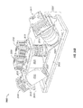
- the imaging sensors may be arranged in a cross track, cross-eyed and long-track, cross-eyed fashion. See e.g., FIGS. 3D & 22A .
- FIG. 22A depicts a concave or retinal camera array assembly 2200 from a rear right side perspective view. Whereas FIG. 22A depicts a 15-camera array, the system works equally well when utilizing any number of imaging sensors from 1 to any number.
- Assembly 2200 is similar in composition, construction and operation to assembly 300 .
- Assembly 2200 comprises a first imaging array 2202 , a second imaging array 2204 and a third imaging array 2206 .
- Array 2204 is configured as a primary sensor array, disposed within assembly 2200 such that the focal axis 2208 of its primary imaging sensor 2210 is directed downwardly from assembly 2200 , orthogonal to a target area 2212 along a terrain 2214 .
- Assembly 2200 is adaptably mountable to a vehicle that moves, with respect to terrain 2214 , along a flight path 2216 .
- Arrays 2202 , 2204 and 2206 are configured within assembly 2200 as sub-assemblies of imaging sensors.
- Array 2202 is offset, with respect to flight path 2216 , in front of mount unit 2204 by angular offset 2218 .
- array 2206 is offset, with respect to flight path 2216 , behind array 2204 by angular offset 2220 .
- Angular offset 2218 is selected such that focal axis 2222 of primary imaging sensor 2224 disposed within mount unit 2202 is directed downward toward target area 2212 forming angle 2232 with the target surface.
- Angular offset 2220 is selected such that the focal axis 2228 of primary imaging sensor 2230 disposed within mount unit 2206 is directed downward toward target area 2212 forming angle 2226 with the target surface.
- angular offsets 2218 and 2220 are equal, but they may be different to provide a desired imaging effect.
- the focal axes of the other individual imaging sensors disposed within mount units 2202 , 2204 and 2206 form similar angular relationships to the target area 2212 and one another, subject to their relative positions along the mount units.
- the imaging sensors may be arranged in a alternative along track, cross-eyed and across-track, cross-eyed fashion. See e.g., FIGS. 3E & 22B .
- FIG. 22B depicts a concave or retinal camera array assembly 2200 from a front right side perspective view.
- Array 2204 is configured as a primary sensor array, disposed within assembly 2200 such that the focal axis 2208 of its primary imaging sensor 2210 is directed downwardly from assembly 2200 , orthogonal to a target area 2212 along a terrain 2214 .
- Mount unit 2202 is offset, with respect to perpendicular 2234 of flight path (or track) 2216 , to the left (viewing the array from the rear) of mount unit 2204 by angular offset 2218 .
- mount unit 2206 is offset, with respect to perpendicular 2234 of flight path 2216 , to the right (viewing the array from the rear) of mount unit 2204 by angular offset 2220 .
- Angular offset 2218 is selected such that focal axis 2222 of primary imaging sensor 2224 disposed within mount unit 2202 is directed downward toward target area 2212 forming angle 2232 with the target surface.
- Angular offset 2220 is selected such that the focal axis 2228 of primary imaging sensor 2230 disposed within mount unit 2206 is directed downward toward target area 2212 forming angle 2226 with the target surface.
- angular offsets 2218 and 2220 are equal, but they may be different to provide a desired imaging effect.
- the focal axes of the other individual imaging sensors disposed within mount units 2202 , 2204 and 2206 form similar angular relationships to the target area 2212 and one another, subject to their relative positions along the mount units.
- FIG. 23 depicts a concave or retinal camera array assembly 2300 from a bottom view. Whereas FIG. 23 depicts a 25-camera array, the system works equally well when utilizing any number of imaging sensors from 1 to any number.
- Assembly 2300 comprises a primary compound concave curvilinear mount unit 2302 and a plurality of compound curvilinear mount units 2304 that are formed of a size and curvatures sufficient to offset and arch over or contact mount unit 2302 at various angular intervals. Any number of mount units 2304 may be employed, and may be so numerous as to form a dome structure for mounting sensors.
- assembly 2300 may comprise two mount units in an orthogonal (i.e., 90°) relationship with one another.
- Another assembly, having three mount units, may be configured such that the angular displacement between the mount units is 60°.
- a primary imaging sensor 2306 is centrally disposed along the concave side of mount unit 2302 , with its focal axis directed orthogonally downward from assembly 2300 .
- a number of imaging sensors 2308 are disposed, in accordance with the teachings of the present invention, along the concave sides of mount units 2302 and 2304 in a “cross-eyed” fashion.
- the cross-eyed imaging sensors 2308 are alternatively disposed along mount units 2302 and 2304 such that the focal axis of each imaging sensor converges upon the focal axis of imaging sensor 2306 at an intersection area (not shown), and aligns its field of view with a target area opposite its respective position in the array.
- assembly 2300 provides the ability to produce images having customizable FOVs, of a generally circular nature. Depending on the mount units and imaging sensors utilized, assembly 2300 may be deployed to produce stereoscopic images. In alternative embodiments, any number of mount units, containing any number of imaging sensors having various shapes and sizes, may be combined to provide imaging data on any desired target region.
- the attachment members 318 are of a permanent and fixed nature (e.g., welds)
- the spatial relationship between the aperture 320 , the cameras, and their lines of sight remain fixed as will the spatial relationship between image areas 326 , 328 , 332 , 336 and 340 .
- Such a configuration may be desirable in, for example, a satellite surveillance application where the camera array assembly 300 will remain at an essentially fixed distance from region 322 .
- the position and alignment of the cameras is set such that areas 326 , 328 , 332 , 336 and 340 provide full imaging coverage of region 322 .
- attachment members 318 are of a temporary or adjustable nature, however, it may be desirable to selectively adjust, either manually or by remote automation, the position or alignment of the cameras so as to shift, narrow or widen areas 326 , 328 , 332 , 336 and 340 —thereby enhancing or altering the quality of images collected by the camera array assembly 300 .
- the rigid mount unit may or may not be affixed to a rigid mount plate.
- the mount unit is any rigid structure to which at least one imaging sensor may be affixed.
- the mount unit may be a housing, which encloses the imaging sensor, but may be any rigid structure including a brace, tripod, or the like.
- an imaging sensor means any device capable of receiving and processing active or passive radiometric energy, i.e., light, sound, heat, gravity, and the like, from a target area.
- imaging sensors may include any number of digital cameras, including those that utilize a red-blue-green filter, a bushbroom filter, or a hyperspectral filter, LIDAR sensors, infrared sensors, heat-sensing sensors, gravitometers and the like.
- Imagining sensors do not include attitude measuring sensors such as gyroscopes, GPS devices, and the like devices, which serve to orient the vehicle with the aid of satellite data and/or inertial data.
- the multiple sensors are different.
- single, i.e., at least one, rigid mount unit may be affixed to the same rigid mount plate.
- multiple, i.e., at least two, rigid mount units may be affixed to the same rigid mount plate.
- the mount unit preferably has an aperture through which light and/or energy may pass.
- the mount plate is preferably planer, but may be non-planer.
- the mount plate preferably has aperture(s) in alignment with the aperture(s) of the mount unit(s) through which light and/or energy may pass.
- a rigid structure is one that flexes less than about 100 th of a degree, preferably less than about 1,000 th of a degree, more preferably less than about 10,000 th of a degree while in use.
- the rigid structure is one that flexes less than about 100 th of a degree, preferably less than about 1,000 th of a degree, more preferably less than about 10,000 th of a degree while secured to an aircraft during normal, i.e., non-turbulent, flight.
- Objects are rigidly affixed to one another if during normal operation they flex from each other less than about 100 th of a degree, preferably less than about 1,000 th of a degree, more preferably less than about 10,000 th of a degree.
- Camera 310 is designated as the principal camera.
- the image plane 326 of camera 310 serves as a plane of reference.
- the orientations of the other cameras 306 , 308 , 312 and 314 are measured relative to the plane of reference.
- the relative orientations of each camera are measured in terms of the yaw, pitch and roll angles required to rotate the image plane of the camera to become parallel to the plane of reference.
- the order of rotations is preferably yaw, pitch, and roll.
- the imaging sensors affixed to the mount unit(s) may not be aligned in the same plane. Instead, the angle of their mount relative to the mount angle of a first sensor affixed to the first mount unit, preferably the principle nadir camera of the first mount unit, may be offset. Accordingly, the imaging sensors may be co-registered to calibrate the physical mount angle offset of each imaging sensor relative to each other.
- multiple, i.e., at least two, rigid mount units are affixed to the same rigid mount plate and are co-registered.
- the cameras 306 through 314 are affixed to a rigid mount unit and co-registered.
- the geometric centerpoint of the AMU preferably a gyroscope
- the physical position of the first sensor affixed to the first mount unit preferably the principle nadir camera of the first mount unit, is calculated relative to a reference point, preferably the geometric centerpoint of the AMU.
- the physical position of all remaining sensors within all mount units are calculated—directly or indirectly—relative to the same reference point.
- the boresight angle of a sensor is defined as the angle from the geometric center of that sensor to a reference plane.
- the reference plane is orthogonal to the target area.
- the boresight angle of the first sensor may be determined using the ground target points.
- the boresight angles of subsequent sensors are preferably calculated with reference to the boresight angle of the first sensor.
- the sensors are preferably calibrated using known ground targets, which are preferably photo-identifiable, and alternatively calibrated using a self-locking flight path or any other method as disclosed in U.S. Publication No. 2004/0054488A1, now U.S. Pat. No. 7,212,938B2, the disclosure of which is hereby incorporated by reference in full.
- the imaging sensor within the second mount unit may be any imaging sensor, and is preferably a LIDAR.
- the second imaging sensor is a digital camera, or array of digital cameras.
- the boresight angle of the sensor(s) affixed to the second mount unit are calculated with reference to the boresight angle of the first sensor.
- the physical offset of the imaging sensor(s) within the second mount unit may be calibrated with reference to the boresight angle of the first sensor within the first mount unit.
- images of areas 336 , 328 , 326 , 332 and 340 taken by cameras 306 through 314 , respectively, are illustrated from an overhead view. Again, because of the “cross-eyed” arrangement, the image of area 336 is taken by camera 306 , the image of area 340 is taken by camera 314 , and so on. In one embodiment of the present invention, images other than those taken by the center camera 310 take on a trapezoidal shape after perspective transformation. See e.g., FIG. 4A . Cameras 306 through 314 form an array along axis 316 that is, in most applications, pointed down vertically.
- cameras 308 , 310 and 312 form an ortho array along axis 316 that is pointed down vertically, and cameras 306 and 314 form an oblique array also along axis 316 . See e.g., FIGS. 4B & 4C .
- infrastructure information such as condition of insulators/conductors, transformers transmission lines and transmission towers and location of ground vegetation, trees/foliage, fences and roads with respect to such structures may be obtained.
- a second array of cameras, configured similar the array of cameras 306 through 314 is aligned with respect to the first array of cameras to have an oblique view providing a “heads-up” perspective.
- the angle of declination from horizontal of the heads-up camera array assembly may vary due to mission objectives and parameters but angles of 25-45 degrees are typical.
- Other alternative embodiments, varying the mounting of camera arrays, are similarly comprehended by the present invention. See e.g., FIGS. 4D & 4E .
- the relative positions and attitudes of the cameras are precisely measured and calibrated so as to facilitate image processing in accordance with the present invention.
- an external mechanism e.g., a GPS timing signal
- a mosaicing module then renders the individual input images from such an array into an ortho-rectified compound image (or “mosaic”), without any visible seams between the adjacent images.
- the mosaicing module performs a set of tasks comprising: determining the geographical boundaries and dimensions of each input image; projecting each input image onto the mosaic with accurate geographical positioning; balancing the color of the images in the mosaic; and blending adjacent input images at their shared seams.
- the exact order of the tasks performed may vary, depending upon the size and nature of the input image data.
- the mosaicing module performs only a single transformation to an original input image during mosaicing. That transformation can be represented by a 4 ⁇ 4 matrix. By combining multiple transformation matrices into a single matrix, processing time is reduced and original input image sharpness is retained.
- pixels in the mosaic may not be mapped to by any pixels in the input images (i.e., input pixels). Warped lines could potentially result as artifacts in the mosaic.
- Certain embodiments of the present invention overcome this with a super-sampling system, where each input and output pixel is further divided into an n ⁇ m grid of sub-pixels. Transformation is performed from sub-pixels to sub-pixels. The final value of an output pixel is the average value of its sub-pixels for which there is a corresponding input sub-pixel. Larger n and m values produce mosaics of higher resolution, but do require extra processing time.
- the mosaicing module may utilize the following information: the spatial position (e.g., x, y, z coordinates) of each camera's focal point at the time an input image is captured; the attitude (i.e., yaw, pitch, roll) of each camera's image plane relative to the target region's ground plane at the time an input image was captured; each camera's fields of view (i.e., along track and cross track); and the Digital Terrain Model (DTM) of the area.
- the attitude can be provided by the AMUs associated with the system.
- Digital terrain models (DTMs) or Digital surface models (DSMs) can be created from information obtained using a LIDAR module 118 .
- LIDAR is similar to the more familiar radar, and can be thought of as laser radar.
- radar radio waves are transmitted into the atmosphere that scatters some of the energy back to the radar's receiver.
- LIDAR also transmits and receives electromagnetic radiation, but at a higher frequency since it operates in the ultraviolet, visible and infrared region of the electromagnetic spectrum.
- LIDAR transmits light out to a target area. The transmitted light interacts with and is changed by the target area. Some of this light is reflected/scattered back to the LIDAR instrument where it can be analyzed. The change in the properties of the light enables some property of the target area to be determined. The time for the light to travel out to the target area and back to LIDAR device is used to determine the range to the target.
- DTM and DSM data sets can also be captured from the camera array assembly.
- Traditional means of obtaining elevation data may also be used such as stereographic techniques.
- Range finder LIDAR is the simplest LIDAR and is used to measure the distance from the LIDAR device to a solid or hard target.
- DIAL LIDAR is used to measure chemical concentrations (such as ozone, water vapor, pollutants) in the atmosphere.
- a DIAL LIDAR uses two different laser wavelengths that are selected so that one of the wavelengths is absorbed by the molecule of interest while the other wavelength is not. The difference in intensity of the two return signals can be used to deduce the concentration of the molecule being investigated.
- Doppler LIDAR is used to measure the velocity of a target.
- the wavelength of the light reflected/scattered off the target will be changed slightly. This is known as a Doppler-shift and therefore Doppler LIDAR. If the target is moving away from the LIDAR, the return light will have a longer wavelength (sometimes referred to as a red shift), if moving towards the LIDAR the return light will be at a shorter wavelength (blue shifted).
- the target can be either a hard target or an atmospheric target (e.g. microscopic dust and aerosol particles that are carried by the wind.
- a camera's focal point is preferably used as a perspective transformation center. Its position in space may be determined, for example, by a multi-frequency carrier phase post-processed GPS system mounted on the host craft.
- the offsets, in three dimensions, of a camera's focal point are preferably carefully measured against the center of the GPS antenna. These offsets may be combined with the position of the GPS antenna, and the orientation of the host craft, to determine the exact position of the camera's focal point.
- the position of the GPS antenna is preferably determined by processing of collected GPS data against similar ground-based GPS antennas deployed at precisely surveyed points.
- One or more AMUs are preferably mounted onboard for attitude determination.
- the attitude of the AMU reference plane relative to the target region's ground plane is preferably measured and recorded at short intervals, with accuracy better than one-hundredth of one degree.
- the attitude of the AMU reference plane may be defined as the series of rotations that can be performed on the axes of this plane to make it parallel to the ground plane. The term “align” could also be used to describe this operation.
- the attitude of center camera 310 (i.e. its image plane), relative to the AMU, is preferably precisely calibrated.
- the attitude of each of the other cameras, relative to center camera 310 is preferably also be carefully calibrated. This dependent calibration is more efficient than directly calibrating each camera.
- the camera array assembly 300 is remounted, only center camera 310 needs to be recalibrated. Effectively, a series of two transformations is applied to an input image from center camera 310 . First, the center camera's image plane is aligned to the AMU plane. Then, the AMU plane is aligned again to the ground plane. These transformations, however, combine into a single operation by multiplying their respective transformation matrices. For images from each of the other cameras, an additional transformation is first performed to align it with the center camera's image plane.
- the position of the focal point of center camera 310 may be determined as described above.
- the x and y components of this position preferably determine the position of the mosaic's nadir point 400 on the ground.
- Field of view (FOV) angles of each camera are known, thus the dimensions of each input image may be determined by the z component of that camera's focal point.
- An average elevation of the ground is preferably determined by computing the average elevation of points in the DTMs of the area, and then each input image is projected to an imaginary horizontal plane at this elevation. Relief displacement is then preferably applied using the DTMs of the area.
- the DTMs can be obtained from many sources including: the USGS 30- or 10-meter DTMs available for most of the US; commercial DTMs; or DTMs obtained by a LIDAR or SAR EMU device mounted on the host craft that captures data concurrently with the cameras.
- the resulting compound image also needs to have radiometric consistency throughout, and no visible seams at the joints between two adjacent images.
- the present invention provides a number of techniques for achieving this goal.
- Exposure time i.e., the time the shutter is open to collect light onto the image plane. The longer the exposure time, the lighter the resultant image becomes. Exposure time must adapt to changes in ambient lighting caused by conditions such as: cloud coverage; the angle and position of the sun relative to the camera; and so forth. Optimal exposure time may also depend on a camera's orientation with respect to lighting sources (e.g., cameras pointing towards a sunlit object typically receive more ambient light than those pointing towards a shaded object). Exposure time is adjusted to keep the average intensity of an image within a certain desired range. For example, in 24-bit color images each Red, Green and Blue component can have intensity values from 0 to 255. In most instances, however, it is desirable to keep the average intensity at a mean value (i.e., 127).
- an exposure control module controls exposure time for each of the cameras or imaging sensors. It examines each input image and calculates average image intensity. Based on a moving average (i.e., average intensity of the last X number of images), the exposure control module determines whether to increase or decrease exposure time. The module can use a longer running average to effect a slower reaction to changes in lighting conditions, with less susceptibility to unusually dark or light images (e.g., asphalt roads or water). The exposure control module controls exposure time for each camera separately.
- the exposure control module computes the average intensity of an image by selecting only green-dominant pixels. For example, if an image has 1 million pixels and 300,000 are green-dominant, only those 300,000 green-dominant pixels are included in the calculation of average intensity. This results in an imaging process that is less susceptible to biasing caused by man-made structures and water bodies, whose pixels are usually not green-dominant. As previously noted, it is desirable to maintain an intensity value of about 127. When intensity value is over 127 (i.e., over-exposed), exposure time is reduced so that less light is captured. Similarly, when intensity value is under 127 (i.e., under-exposed), exposure time is increased so that more light is captured.
- the exposure control module reduces intensity differences between input images. Nonetheless, further processing is provided to enhance tonal balance.
- factors e.g., lens physics, atmospheric conditions, spatial/positional relationships of imaging devices
- More light is received in the center of a camera or sensor than at the edges.
- the mosaicing module of the present invention addresses this with an anti-vignetting function, illustrated in reference now to FIG. 5 .
- a number of focal columns 500 , 502 , 504 , 506 and 508 converge from image plane 509 and cross through focal point 510 as they range across imaging target area 512 (e.g., ground terrain).
- Columns 500 through 508 may comprise individual resolution columns of a single camera or sensor, or may represent the focal axes of a number of independent cameras or sensors.
- column 504 serves as the axis and point 513 at which column 504 intersects image plane 509 serves as a principal point.
- the exposure control module applies an anti-vignetting function multiplying the original intensity of an input pixel with a column-dependent anti-vignetting factor.
- the off-axis angle 514 is: zero for center column 504 ; larger for columns 502 and 506 ; and larger still for columns 500 and 508 .
- the overall field of view angle 516 (FOVx angle) is depicted between columns 504 and 508 .
- Each set of input images needs to be stitched into a mosaic image. Even though the exposure control module regulates the amount of light each camera or sensor receives, the resulting input images may still differ in intensity.
- the present invention provides an intensity-balancing module that compares overlapping area between adjacent input images, to further balance the relative intensities. Because adjoining input images are taken simultaneously, the overlapping areas should, in theory, have identical intensity in both input images. However, due to various factors, the intensity values are usually not the same. Some such factors causing intensity difference could include, for example, the exposure control module being biased by unusually bright or dark objects present in the field of view of only a particular camera, or the boresight angles of cameras being different (i.e., cameras that are more slanted receive less light than those more vertical).
- a correlation vector (fR, fG, FB) is determined using, for example, the following process. Let V be a 3 ⁇ 1 vector representing the values (R, G and B) of a pixel:
- a correlation matrix C may be derived as:
- the correlation matrix scales pixel values of the secondary image so that the average intensity of the overlapping area of the secondary image becomes identical to the average intensity of the overlapping area of the reference image.
- the second image can be balanced to the reference image by multiplying its pixel values by the correlation matrix.
- a center image is considered the reference image.
- the reference image is first copied to the compound image (or mosaic). Overlapping areas between the reference image and an adjoining image (e.g., the near left image) are correlated to compute a balancing correlation matrix (BCM).
- BCM balancing correlation matrix
- the BCM will be multiplied with vectors representing pixels of the adjoining image to make the intensity of the overlapping area identical in both images.
- I (center) Average intensity of overlapping area in center image
- I (adjoining) Average intensity of overlap in adjoining image
- Balancing factor I (center)/ I (adjoining)
- the balancing factor for each color channel (i.e., red, green and blue) is independently computed. These three values form the BCM.
- the now-balanced adjoining image is copied to the mosaic. Smooth transitioning at the border of the copied image is providing by “feathering” with a mask.
- This mask has the same dimension as the adjoining image and comprises a number of elements. Each element in the mask indicates the weight of the corresponding adjoining image pixel in the mosaic. The weight is zero for pixels at the boundary (i.e. the output value is taken from the reference image), and increases gradually in the direction of the adjoining image until it becomes unity—after a chosen blending width has been reached. Beyond the blending area, the mosaic will be entirely determined by the pixels of the adjoining image. Similarly, the overlaps between all the other constituent input images are analyzed and processed to compute the correlation vectors and to balance the intensities of the images.
- FIG. 6 depicts a strip 600 being formed in accordance with the present invention.
- V be a vector that represents the R, G and B values of a pixel:
- V R G B
- h the transition width of region 608
- y the along-track 606 distance from the boundary 610 of the overlapped region to a point A, whose pixel values are represented by V.
- C the correlation matrix:
- the mosaic can be divided into a number of segments corresponding to the position of the original input images that make up the mosaic. The process described above is applied to each segment separately to provide better local color consistency.
- pixels at the border of two segments may create vertical seams (assuming north-south flight lines).
- balancing factors for pixels in this area have to be “transitioned” from that of one segment to the other. This is explained now with reference to FIG. 7 .
- FIG. 7 depicts a strip 700 being formed in accordance with the present invention.
- a base mosaic 702 and a new segment 704 overlap in area 706 .
- Mosaic 702 and another new segment 708 overlap in area 710 .
- Segments 704 and 708 overlap in area 712 , and areas 706 , 710 and 712 all overlap and coincide at area 714 .
- point 716 serves as an origin for y-axis 718 and x-axis 720 . Movement along y-axis 718 represents movement along the flight path of the imaging system.
- Point 716 is located at the lower left of area 714 .
- the dimensions of a strip are determined by the minimum and maximum x and y values of the constituent mosaics.
- An output strip is initialized to a background color.
- a first mosaic is transferred to the strip.
- the next mosaic (along the flight path) is processed next.
- Intensity values of the overlapping areas of the new mosaic and the first mosaic are correlated, separately for each color channel.
- the new mosaic is divided into a number of segments corresponding to the original input images that made up the mosaic.
- a mask matrix, comprising a number of mask elements, is created for the new mosaic.
- a mask element contains the correlation matrix for a corresponding pixel in the new mosaic. All elements in the mask are initialized to unity.
- the size of the mask can be limited to just the transition area of the new mosaic.
- the correlation matrix is calculated for the center segment.
- the mask area corresponding to the center segment is processed.
- the values of the elements at the edge of the overlap area are set to the correlation vector.
- gradually moving away from the first mosaic along the strip the components of the correlation matrix are either increased or decreased (whether they are less or more than unity, respectively) until they become unity at a predetermined transition distance.
- the area of the mask corresponding to a segment adjoining the center segment is then processed similarly.
- the area 714 formed by the first mosaic and the center and adjoining segments of the new image requires special treatment. Because the correlation matrix for the adjoining segment may not be identical to that of the center segment, a seam may appear at the border of the two segments in the overlap area 714 with the first mosaic.
- the corner is influenced by the correlation matrices from both segments.
- its correlation matrix is the distance-weighted average of the two segments, evaluated as follows:
- V 1 is the balanced RGB vector based on segment 704 ;
- V 2 is the balanced RGB vector based on segment 708 ;
- a color fidelity (i.e., white-balance) filter is applied. This multiplies R and B components with a determinable factor to enhance color fidelity. The factor may be determined by calibrating the cameras and lenses.
- the color fidelity filter ensures that the colors in an image retain their fidelity, as perceived directly by the human eye. Within the image capture apparatus, the Red, Green and Blue light receiving elements may have different sensitivities to the color they are supposed to capture.
- a “while-balance” process is applied—where image of a white object is captured. Theoretically, pixels in the image of that white object should have equivalent R, G and B values.
- the average color values for each R, G and B may be avgR, avgG and avgB, respectively.
- the R, G and B values of the pixels are multiplied by the following ratios:
- R values are multiplied by the ratio avgG/avgR;
- the present invention provides an intensity normalization module that normalizes the average intensity of each strip so that the mean and standard deviation are of a desired value. For example, a mean of 127 is the norm in photogrammetry. A standard deviation of 51 helps to spread the intensity value over an optimal range for visual perception of image features.
- Each strip may have been taken in different lighting conditions and, therefore, may have different imaging data profiles (i.e., mean intensity and standard deviation).
- This module normalizes the strips, such that all have the same mean and standard deviation. This enables the strips to be stitched together without visible seams.
- tiled mosaics for an area of interest.
- Finished tiles can correspond to the USGS quads or quarter-quads.
- Stitching strips into mosaics is similar to stitching mosaics together to generate strips, with strips now taking the role of the mosaics.
- problems may arise if the line crosses elevated structures such as buildings, bridges, etc. This classic problem in photogrammetry arises from the parallax caused by the same object being looked at from two different perspectives.
- one strip may present a view from one side of the building while another strip presents a view from another side of the building.
- the resulting mosaic may look like a tepee.
- a terrain-guided mosaicing process may be implemented to guide the placement of a seam line.
- LIDAR or DEM data collected with, or analyzed from, image data may be processed to determine the configuration and shaping of images as they are mosaiced together.
- a seam line may not be a straight line—instead comprising a seam line that shifts back and forth to snake through elevated structures.
- Process 800 begins with a series 802 of one, or more, raw collected images. Images 802 are then processed through a white-balancing process 804 , transforming them into a series of intermediate images. Series 802 is then processed through anti-vignetting function 806 before progressing to the orthorectification process 808 .
- orthorectification may rely on position and attitude data 810 from the imaging sensor system or platform, and on DTM data 812 .
- DTM data 812 may be developed from position data 810 and from, for example, USGS DTM data 814 or LIDAR data 816 .
- Series 802 is now ortho-rectified and processing continues with color balancing 818 .
- series 802 is converted by mosaicing module 820 into compound image 822 .
- Module 820 performs the mosaicing and feathering processes during this conversion.
- one or more compound images 822 are further combined in step 824 , by mosaicing with a gradient and feathering, into image strip 826 .
- Image strips are processed through intensity normalization 828 .
- the now normalized strips 828 are mosaiced together in step 830 , again by mosaicing with a gradient and feathering, rendering a finishing tiled mosaic 832 .
- the mosaicing performed in step 830 may comprise a terrain-guided mosaicing, relying on DTM data 812 or LIDAR data 816 .
- FIG. 9 illustrates diagrammatically how photos taken with the camera array assembly may be aligned to make an individual frame.
- This embodiment shows a photo patter illustration looking down from a vehicle, using data ortho-rectified from five cameras.
- FIG. 10 is a block diagram of the processing logic according to certain embodiments of the present invention.
- the processing logic accepts one or more inputs, which may include elevation measurements 1002 , attitude measurements 1004 and/or photo and sensor imagery 1006 .
- Certain inputs may be passed through an initial processing step prior to analysis, as is shown in block 1008 , wherein the attitude measurements are combined with data from ground control points.
- Elevation measurements 1002 and attitude measurements 1004 may be combined to generate processed elevation data 1010 .
- Processed elevation data 1010 may then be used to generate elevation DEM 1014 and DTM 1016 .
- attitude measurements 1006 may be combined with photo and sensor imagery 1006 to generate georeferenced images 1012 , which then undergo image processing 1018 , which may include color balancing and gradient filtering.
- either DTM 1016 or a USGS DEM 1022 is combined with processed images 1018 to generate ortho-rectified imagery 1024 .
- Ortho-rectified imagery 1024 then feeds into self-locking flight lines 1026 .
- Balancing projection mosaicing 1028 then follows, to generate final photo output 1030 .
- the present invention may capture ortho and/or oblique image data using a camera array as depicted in FIGS. 3A-3E , 22 A- 22 B and 23 and may merge the image data with attitude and positional measurements in order to create a three dimensional image (i.e., 3D point cloud) or digital elevation model (DEM).
- 3D point cloud or DEM is a representation of the ground surface including man-made structures.
- the 3D point cloud or DEM may be calculated using stereographic techniques from the image data, or, alternatively, provided directly by LIDAR or an existing DEM.
- the 3D point cloud or DEM may be calculated from any overlapping image data from a single camera overlapping in time or overlapping image data from any two cameras overlapping in space and/or time.
- the sequence of overlapping images may be ortho-rectified using standard photogrammetry techniques to produce an orthomap in which each pixel has an unique latitude and longitude coordinate as discussed above and a unique elevation coordinate.
- overlapping ortho and/or oblique images are needed to determine a stereoscopic parallax and create a stereo/three dimensional view as depicted in FIG. 24 .
- the overlapping images may be obtained from a single camera overlapping in time or from any two cameras overlapping in space and/or time.
- FIG. 24 depicts a sequence of overlapping oblique images obtained from an oblique camera array at two different times. Although the camera array assembly of FIG. 24 is shown, other ortho and/or oblique camera array assemblies may be used.
- the adjoining borders of image area 2402 and 2404 should overlap slightly. In an embodiment, the adjoining borders of image areas 2402 and 2404 overlap between about 1% and about 100%.
- the adjoining borders of image areas 2402 and 2404 overlap between about 20% to about 70%. In another embodiment, the adjoining borders of image areas 2402 and 2404 overlap between about 50% and about 70%. In another embodiment, a sidelap area 2406 overlaps between about 20% and about 30% and the forelap area 2408 overlaps about 50% to about 70%.
- the elevation of an object may be calculated using standard stereographic techniques from overlapping ortho and/or oblique images or, alternatively, it may be obtained directly from LIDAR or a pre-existing DEM as described below.
- the principal point of each image e.g., principal point 2502 of image 2402
- the principal point of each image is located using direct calculation techniques that determine virtual corner fiduciary coordinates after correcting for yaw, pitch and roll by the AMU or aerial triangularization techniques (e.g., upper left and lower right (UL-LR) and upper right and lower left (UR-LL)) as depicted in FIG. 25 .
- the conjugate principal point which is the principal point of the adjacent image is similarly located.
- the sequence of oblique images are aligned so that the principal points and conjugate principal points are on a straight line.
- the line between the principal point and the conjugate principal point is the flight path (or track).
- Relief displacement is due to differences in the relative elevations of objects from a specific ground plane. All objects that extend above or below a specified ground plane will exhibit image displacement in proportion to the object's height. The taller the object, the greater the relief displacement. Tall objects can exhibit image displacement even from great altitude.
- Radial displacement is due differences in the relative distance of objects from the principal point. All objects that are away from the principal point will exhibit radial displacement in proportion to the object's distance from the point. The larger the distance, the greater the radial displacement.
- a stereoscopic parallax is caused by capturing images of the same object from different points of view along the flight path.
- FIG. 11 is an illustration of a lateral oversampling pattern 1100 looking down from a vehicle according to certain embodiments of the present invention showing minimal lateral oversampling.
- the central nadir region 1102 assigned to the center camera overlaps only slightly with the left nadir region 1104 and right nadir region 1106 , so that overlap is minimized.
- FIG. 12 is an illustration of a lateral oversampling pattern 1200 looking down from a vehicle according to certain embodiments of the present invention showing a greater degree of lateral oversampling.
- the central nadir region 1202 shows a high degree of overlap with left nadir region 1204 and right nadir region 1206 .
- FIG. 13 is an illustration of a flight line oversampling pattern 1300 looking down from a vehicle according to certain embodiments of the present invention showing a certain degree of flight line oversampling but minimal lateral oversampling.
- Central nadir regions 1302 and 1304 are overlapped to one another along the flight line, but do not overlap laterally with left nadir regions 1306 and 1308 or with right nadir regions 1310 and 1312 .
- FIG. 14 is an illustration of flight line oversampling looking down from a vehicle according to certain embodiments of the present invention showing significant flight line oversampling as well as significant lateral oversampling. It can be seen that each of the central nadir regions 1402 through 1406 are significantly overlapped with one another as well as with left nadir regions 1408 through 1412 and right nadir regions 1414 through 1418 . Left nadir regions 1408 through 1412 are overlapped with one another, as are right nadir regions 1414 through 1418 . Accordingly, each point on the surface is sampled at least twice, and in some cases as many as four times.
- This technique uses the fact that in the area of an image that is covered twice, or more, by different camera sensors, a doubling of the image resolution is possible in both the lateral (across path) and flight line (along path) directions for an overall quadrupling of the resolution.
- FIG. 15 is an illustration of a progressive magnification pattern 1500 looking down from a vehicle according to certain embodiments of the present invention.
- Central nadir region 1502 is bounded on its left and right edges by inner left nadir region 1504 and inner right nadir region 1506 , respectively.
- Inner left nadir region 1504 is bounded on its left edge by outer left nadir region 1508
- inner right nadir region 1506 is bounded on its right edge by outer right nadir region 1510 . Note that these regions exhibit a minimal degree of overlap and oversampling from one to another.
- FIG. 16 is an illustration of a progressive magnification pattern 1600 looking down from a vehicle according to certain embodiments of the present invention.
- Central nadir region 1602 is bounded on its left and right edges by inner left nadir region 1604 and inner right nadir region 1606 , respectively.
- Inner left nadir region 1604 is bounded on its left edge by outer left nadir region 1608
- inner right nadir region 1606 is bounded on its right edge by outer right nadir region 1610 . Note that, as above, these regions exhibit a minimal degree of overlap and oversampling from one to another.
- Within each of the nadir regions 1604 through 1610 there is a central image region 1614 through 1620 shown shaded in grey.
- FIG. 17 is an illustration of a progressive magnification pattern 1700 looking down from a vehicle according to certain embodiments of the present invention.
- a left inner nadir region 1702 and a right inner nadir region 1704 overlap in the center.
- a left intermediate nadir region 1706 and a right intermediate nadir region 1708 are disposed partly outside of regions 1702 and 1704 , respectively, each sharing an overlapping area with the respective adjacent area by approximately 50%.
- An outer left nadir region 1710 and an outer right nadir region 1712 are disposed partly outside of regions 1706 and 1708 , respectively, each sharing an overlapping area with the respective adjacent area by approximately 50%.
- a central image region 1714 is disposed in the center of pattern 1700 , comprised of the central portions of nadir regions 1702 through 1712 .
- FIG. 18 depicts a schematic of the architecture of a system 1800 according to certain embodiments of the present invention.
- System 1800 may include one or more GPS satellites 1802 and one or more SATCOM satellites 1804 .
- One or more GPS location systems 1806 may also be included, operably connected to one or more modules 1808 collecting LIDAR, GPS and/or X, Y, Z location data and feeding such information to one or more data capture system applications 1812 .
- One or more data capture system applications 1812 may also receive spectral data from a camera array 1822 .
- a DGPS 1810 may communicate with one or more SATCOM satellites 1804 via a wireless communications link 1826 .
- One or more SATCOM satellites 1804 may, in turn, communicate with one or more data capture system applications 1812 .
- One or more data capture system applications 1812 may interface with an autopilot 1816 , an SSD and/or a RealTime StitchG system 1820 , which may also interact with one another.
- SSD 1814 may be operably connected to RealTime DEM 1818 .
- RealTime DEM 1818 and RealTime StitchG 1820 may be connected to a storage device, such as disk array 1824 .
- the present invention may employ a certain degree of co-mounted, co-registered oversampling to overcome physical pixel resolution limits.
- These co-mounted, co-registered oversampling techniques work equally well with across track camera arrays or along track camera arrays or any combination thereof.
- FIG. 19 is an illustration of a lateral co-mounted, co-registered oversampling configuration 1900 for a single camera array 112 looking down from a vehicle according to certain embodiments of the present invention showing minimal lateral oversampling. The cameras overlap a few degrees in the vertical sidelap area 1904 and 1908 . Whereas FIG. 19 depicts a 3-camera array, these subpixel calibration techniques work equally well when utilizing any number of camera sensors from 2 to any number of cameras being calibrated.
- the camera sensors may be co-registered to calibrate the physical mount angle offset of each sensor relative to each other and/or to the nadir camera. This provides an initial, “close” calibration. These initial calibration parameters may be entered into an onboard computer system 104 in the system 100 , and updated during flight using oversampling techniques.
- the rectangles labeled A, B, and C represent image areas 1902 , 1906 and 1910 from a 3-camera array C-B-A (not shown). Images of areas 1902 , 1906 and 1910 taken by cameras A through C (not shown), respectively, are illustrated from an overhead view. Again, similar to FIGS. 3 & 4 , because of the “cross-eyed” arrangement, the image of area 1902 is taken by right camera A, the image of area 1906 is taken by center/nadir camera B, and the image of area 1910 is taken by left camera C. Cameras A through C form an array (not shown) that is, in most applications, pointed down vertically.
- the hatched areas labeled A/B and B/C sidelaps represent image overlap areas 1904 and 1908 , respectively.
- the left image overlap area 1904 is where right camera A overlaps with the center/nadir camera B
- the right image overlap area 1908 is where the left camera C overlaps with the center/nadir camera B.
- the camera sensor grid bisects each pixel in the overlap areas 1904 and 1908 , which effectively quadruples the image resolution in these areas 1904 and 1908 via the mechanism of co-mounted, co-registered oversampling.
- this quadrupling of alignment precision between adjacent cameras improves the systems 100 alignment precision for all sensors affixed to a rigid mount plate.
- the cameras and sensors are affixed to a rigid mount unit, which is affixed to the rigid mount plate, as discussed above.
- the angular alignment of adjacent cameras affixed to the rigid mount unit is improved, the angular alignment of the other sensors is also enhanced.
- This enhancement of alignment precision for the other sensors affixed to the rigid mount plate also improves the image resolution for those sensors.
- FIG. 20 A lateral co-mounted, co-registered oversampling configuration 2000 for two overlapping camera arrays 112 is illustrated in FIG. 20 .
- These sub-pixel calibration techniques work equally well with across track camera arrays, along track camera arrays or any combination thereof.
- FIG. 20 is an illustration of a lateral co-mounted, co-registered oversampling configuration 2000 for two overlapping camera arrays 112 looking down from a vehicle according to certain embodiments of the present invention showing maximum lateral oversampling.
- the adjacent cameras overlap a few degrees in the vertical sidelap areas 2006 , 2008 , 2014 and 2016 , and the corresponding cameras overlap completely in the image areas 2002 , 2010 , 2018 and 2004 , 2012 , 2020 .
- FIG. 20 depicts two 3-camera arrays
- these subpixel calibration techniques work equally well when utilizing two overlapping camera arrays with any number of camera sensors from 2 to any number of cameras being calibrated.
- the camera sensors may be co-registered to calibrate the physical mount angle offset of each sensor relative to each other and/or to the nadir camera.
- multiple, i.e., at least two, rigid mount units are affixed to a rigid mount plate and are co-registered. This provides an initial, “close” calibration. These initial calibration parameters may be entered into an onboard computer system 104 in the system 100 , and updated during flight.
- the rectangles labeled A, B, and C represent image areas 2002 , 2010 , 2018 , and 2004 , 2012 , 2020 from two overlapping 3-camera arrays C-B-A (not shown), respectively. Images of areas 2002 , 2010 , 2018 , and 2004 , 2012 , 2020 taken by cameras A through C (not shown) and overlapping cameras A′ through C′ (not shown), respectively, are illustrated from an overhead view. Again, similar to FIGS. 3 & 4 , because of the “cross-eyed” arrangement, the image of area 2002 is taken by right camera A, the image of area 2010 is taken by center/nadir camera B, and the image of area 2018 is taken by left camera C.
- the image of area 2004 is taken by right camera A′
- the image of area 2012 is taken by center camera B′
- the image of area 2020 is taken by left camera C′.
- Cameras A through C and overlapping cameras A′ through C′ form arrays (not shown) that are, in most applications, pointed down vertically.
- the hatched areas labeled A/B and B/C sidelaps represent two overlapping image overlap areas 2006 , 2008 and 2014 , 2016 , respectively.
- the left image overlap areas 2006 , 2008 is where right camera A overlaps with the center/nadir camera B, and where right camera A′ overlaps with the center camera B′, respectively.
- the right image overlap areas 2014 and 2016 is where the left camera C overlaps with the center/nadir camera B, and where the left camera C′ overlaps with the center camera B′.
- the camera sensor grid bisects each pixel in the overlap areas 2006 , 2008 and 2014 , 2016 , which effectively quadruples the image resolution in these areas 2006 , 2008 and 2014 , 2016 via the mechanism of co-mounted, co-registered oversampling.
- the overlapping camera sensor grids bisects each pixel in the sidelap areas 2006 and 2008 , which effectively quadruples the image resolution in these areas 2006 and 2008 via the mechanism of co-mounted, co-registered oversampling.
- the overlapping camera sensor grids bisects each pixel in the sidelap areas 2014 and 2016 , which effectively quadruples the image resolution in these areas 2014 and 2016 .
- This 64 times improvement of alignment precision between adjacent and corresponding cameras enhances the systems 100 alignment precision for all sensors affixed to a rigid mount plate.
- Cameras A through C and, optionally, other sensors are affixed to a first rigid mount unit and cameras A′ through C′ and, optionally, other sensors are affixed to a second rigid mount unit, which are each affixed to a rigid mount plate.
- the angular alignment of adjacent and/or corresponding cameras affixed to the first and/or second rigid mount units is improved, the angular alignment of the other sensors is also enhanced.
- This enhancement of alignment precision for the other sensors affixed to the rigid mount plate also improves the image resolution for those sensors.
- the image resolution is effectively quadrupled for the entire image, not just for the A/B and B/C sidelap overlap areas.
- the overlapping grid detail labeled “OVERLAPPING GRID 4X” represents overlapping areas 2022 and 2024 in right images areas 2018 and 2020 , respectively.
- the overlapping camera sensor grids bisects each pixel in the overlapping areas 2022 and 2024 , which effectively quadruples the image resolution in these areas 2022 and 2024 via the mechanism of co-mounted, co-registered oversampling.
- one camera array is monochrome, and another camera array is red-green-blue. Even though each array covers different color bands, simple image processing techniques are used so that all color bands realize the benefit of this increased resolution. Another advantage provided by these techniques is that, in the case where one camera array is red-green-blue and the other, overlapping camera array is an infrared or near infrared (or some other bandwidth), which results in a superior multi-spectral image.
- FIG. 21 is an illustration of a fore and lateral co-mounted, co-registered oversampling configuration 2100 for two camera arrays 112 looking down from a vehicle according to certain embodiments of the present invention.
- FIG. 21 is an illustration of a fore and lateral co-mounted, co-registered oversampling configuration 2100 for two overlapping camera arrays 112 looking down from a vehicle according to certain embodiments of the present invention showing minimal fore and minimal lateral oversampling.
- the adjacent cameras overlap a few degrees in the vertical sidelap areas 2104 , 2108 , 2124 and 2128 , and the corresponding cameras overlap a few degrees along the horizontal forelap areas 2112 , 2116 and 2120 .
- FIG. 21 depicts two 3-camera arrays, these subpixel calibration techniques work equally well when utilizing two overlapping camera arrays with any number of camera sensors from 2 to any number of cameras being calibrated.
- the camera sensors may be co-registered to calibrate the physical mount angle offset of each sensor relative to each other and/or to the nadir camera.
- multiple, i.e., at least two, rigid mount units are affixed to a rigid mount plate and are co-registered. This provides an initial, “close” calibration. These initial calibration parameters may be entered into an onboard computer system 104 in the system 100 , and updated during flight.
- the rectangles labeled A, B, and C represent image areas 2102 , 2106 and 2110 from a 3-camera array C-B-A (not shown), and the rectangles D, E, and F represent image areas 2122 , 2126 and 2130 from a 3-camera array F-E-D (not shown), respectively.
- Images of areas 2102 , 2106 and 2110 taken by cameras A through C (not shown), and images of areas 2122 , 2126 and 2130 taken by cameras D through F (not shown), respectively, are illustrated from an overhead view. Again, similar to FIGS.
- the rear, left image of area 2102 is taken by rear, right camera A
- the rear, center image of area 2106 is taken by rear, center/nadir camera B
- the rear, right image of area 2110 is taken by rear, left camera C.
- the forward, left image of area 2122 is taken by forward, right camera D
- the forward, center image of area 2126 is taken by forward, center camera E
- the forward, right image of area 2020 is taken by forward, left camera F.
- Cameras A through C and overlapping cameras D through F form arrays (not shown) that are, in most applications, pointed down vertically.
- the vertical hatched areas represent four image overlap areas 2104 , 2108 , 2124 and 2128 .
- the rear, left image overlap area 2104 is where rear, right camera A overlaps with the center/nadir camera B
- the rear, right image overlap area 2108 is where rear, left camera C overlaps with the center/nadir camera B.
- the forward, left image overlap area 2124 is where forward, right camera D overlaps with the center/nadir camera E
- the forward, right image overlap area 2128 is where forward, left camera F overlaps with the center camera E.
- the overlapping grid detail labeled “SIDELAP AREA 4:1” represents overlaping sidelap overlap areas 2104 , 2108 and 2124 , 2128 .
- the camera sensor grid bisects each pixel in the overlap areas 2104 , 2108 , 2124 and 2128 , which effectively quadruples the image resolution in these areas 2104 , 2108 , 2124 and 2128 via the mechanism of co-mounted, co-registered oversampling.
- This quadrupling of alignment precision between adjacent cameras improves the systems 100 alignment precision for all sensors affixed to a rigid mount plate.
- Cameras A through C and, optionally, other sensors are affixed to a first rigid mount unit and cameras D through F and, optionally, other sensors are affixed to a second rigid mount unit, which are each affixed to a rigid mount plate.
- the angular alignment of adjacent cameras affixed to the first or second rigid mount units is improved, the angular alignment of the other sensors affixed to the mount unit is also enhanced.
- This enhancement of alignment precision for the other sensors affixed to the rigid mount plate also improves the image resolution for those sensors.
- the horizontal hatched areas represent three image overlap areas 2112 , 2116 and 2120 .
- the forward, left image overlap area 2112 is where rear, right camera A overlaps with the forward, right camera D
- forward, center image overlap area 2116 is where rear, center/nadir camera B overlaps with the forward, center camera E
- the rear, right image overlap area 2120 is where rear, left camera C overlaps with forward, left camera F.
- the overlapping grid detail labeled “FORELAP AREA 4:1” represents overlaping forelap overlap areas 2112 , 2116 and 2120 .
- the camera sensor grid bisects each pixel in the overlap areas 2112 , 2116 and 2120 , which effectively quadruples the image resolution in these areas 2112 , 2116 and 2120 via the mechanism of co-mounted, co-registered oversampling.
- This quadrupling of alignment precision between corresponding cameras improves the systems 100 alignment precision for all sensors affixed to a rigid mount plate.
- Cameras A through C and, optionally, other sensors are affixed to a first rigid mount unit and cameras D through F and, optionally, other sensors are affixed to a second rigid mount unit, which are each affixed to a rigid mount plate.
- the angular alignment of corresponding cameras affixed to the first or second rigid mount units is improved, the angular alignment of the other sensors is also enhanced.
- This enhancement of alignment precision for the other sensors affixed to the rigid mount plate also improves the image resolution for those sensors.
- the intersecting forelap and sidelap overlap areas 2114 and 2118 in FIG. 21 results in an astonishing overall 64 times improvement in system calibration and camera alignment.
- the intersecting grid detail labeled “QUAD OVERLAP AREA 64:1” represents intersecting forelap and sidelap overlap area 2118 .
- the overlapping camera sensor grids bisects each pixel in the intersecting areas 2114 and 2118 , which effectively quadruples the image resolution in these areas 2114 and 2118 via the mechanism of co-mounted, co-registered oversampling.
- This 64 times improvement of alignment precision between adjacent and corresponding cameras enhances the systems 100 alignment precision for all sensors affixed to a rigid mount plate.
- Cameras A through C and, optionally, other sensors are affixed to a first rigid mount unit and cameras D through E and, optionally, other sensors are affixed to a second rigid mount unit, which are each affixed to a rigid mount plate.
- the angular alignment of adjacent and/or corresponding cameras affixed to the first and/or second rigid mount units is improved, the angular alignment of the other sensors is also enhanced.
- This enhancement of alignment precision for the other sensors affixed to the rigid mount plate also improves the image resolution for those sensors.
- one camera array is monochrome, and another camera array is red-green-blue. Even though each array covers different color bands, simple image processing techniques are used so that all color bands realize the benefit of this increased resolution. Another advantage provided by these techniques is that, in the case where one camera array is red-green-blue and the other, overlapping camera array is an infrared or near infrared (or some other bandwidth), which results in a superior multi-spectral image.
- these techniques may be used to overcome the resolution limits imposed on camera systems due to the inability of optical glass to resolve “very small” objects. As discussed above, these techniques work equally well with across track camera arrays, along track camera arrays or any combination thereof. In particular, there are known physical limits to the ability of optical glass in camera lenses to resolve very small objects. This is often called “the resolving limit of glass”. For example, if 1 millimeter pixels are required from 10,000 feet of altitude, the use of an extremely high magnification telescopic lens would be required to obtain a ground swath of about 100 feet.
- the systems 100 imaging sensor alignment in the rigid mount unit(s) affixed to the rigid mount plate and related calibration techniques provide a unique solution to this problem, as described above.
- the resolving limitations of glass can effectively be overcome.
- a single camera array results in 1 times (or no) oversampling benefits.
- two overlapping camera arrays results in 4 times overall improvement in both image resolution and overall geospatial horizontal and vertical accuracy.
- three overlapping camera arrays results in 16 times overall improvement
- four overlapping camera arrays results in 64 times overall improvement, and so on.
- subpixel calibration techniques may be combined with the self-locking flight path techniques, as disclosed in U.S. Publication No. 2004/0054488A1, now U.S. Pat. No. 7,212,938 B2, the disclosure of which is hereby incorporated by reference in full.
- the present invention may also employ flight line oversampling as well to further improve the image resolution, as shown in FIGS. 13-17 .
- flight line oversampling techniques work equally well with across track camera arrays, along track camera arrays or any combination thereof.
- the flight lines overlap each other in an image region because each flight line is parallel to one another.
- These overlapping image regions may be used to calibrate the sensors by along-track and cross-track parallax of images in adjacent flight lines using stereographic techniques.
- the self-locking flight path may comprise any pattern that produces at least three substantially parallel travel lines out of a group of three or more travel lines. Further, at least one of the travel lines should be in an opposing direction to the other substantially parallel travel lines.
- the travel pattern comprises at least one pair of travel lines in a matching direction and at least one pair of travel lines in an opposing direction.
- the self-locking flight path technique includes an algorithm to significantly reduce these positional errors. This reduction in positional errors is especially important in the outside, or far left and far right “wing” image areas where the greatest positional errors occur.
- these positional improvements may be realized by using a pattern matching technique to automatically match a pixel pattern area obtained from a flight line (e.g., North/South) with the same pixel pattern area obtained from an adjacent flight line (e.g., North/South).
- a pattern matching technique to automatically match a pixel pattern area obtained from a flight line (e.g., North/South) with the same pixel pattern area obtained from an adjacent flight line (e.g., North/South).
- the latitude/longitude coordinates from one or more GPS location systems may be used to accelerate this pattern matching process.
- these subpixel calibration and self-locking flight path techniques may be combined with stereographic techniques because stereographic techniques rely heavily on the positional accuracy of each pixel relative to all other pixels.
- these techniques improve the stereographic image resolution and overall geospatial horizontal and vertical accuracy, especially, in the far left and far right “wing” image areas, where the greatest positional errors occur.
- stereographic techniques are used to match known elevation data with the improved stereographic datasets. Accordingly, the combined subpixel calibration, self-locking flight path and stereographic techniques provide a greatly improved Digital Elevation Model, which results in superior image.
- these subpixel calibration and self-locking flight path techniques may be used to provide a dynamic, RealTime calibration of the system 100 .
- these techniques provide the ability to rapidly “roll on” one or more camera array assemblies 112 onto the system 100 , to immediately begin collecting image data of a target area and to quickly produce high-quality images because the individual sensors have been initially calibrated in the rigid mount unit(s) affixed to the rigid mount plate, as discussed above.
- the camera sensors are co-registered to calibrate the physical mount angle offset of each sensor relative to each other and/or to the nadir camera.
- multiple, i.e., at least two, rigid mount units are affixed to a rigid mount plate and are co-registered. This provides an initial, “close” calibration.
- These initial calibration parameters may be entered into an onboard computer system 104 in the system 100 , and updated during flight using oversampling techniques, as discussed above.
- the system 100 comprises a RealTime, self-calibrating system to update the calibration parameters.
- the onboard computer 104 software comprises a RealTime software “daemon” (i.e., a background closed-loop monitoring software) to constantly monitor and update the calibration parameters using the co-mounted, co-registered oversampling and flight line oversampling techniques, as discussed above.
- the RealTime daemon combines subpixel calibration, self-locking flight path and stereographic techniques to improve the stereographic image resolution and overall geospatial horizontal and vertical accuracy.
- stereographic techniques are used to match known elevation data to the improved stereographic datasets. Accordingly, the combined subpixel calibration, self-locking flight path and stereographic techniques provide a greatly improved Digital Elevation Model, which results in superior image.
- the system 100 comprises a RealTime GPS data system to provide GPS input data. Calibration accuracy is driven by input data from electronic devices such as a GPS and an IMU, and by calibration software which is augmented by industry standard GPS and IMU software systems. Accordingly, a key component of this RealTime, self-calibrating system is a RealTime GPS input data via a potentially low bandwidth communication channel such as satellite phone, cell phone, RF modem, or similar device. Potential sources for the RealTime GPS input data include project controlled ad-hoc stations, fixed broadcast GPS locations (or similar) or inertial navigation via an onboard IMU.
- the present invention may employ anti-vibration and isothermal methods to further reduce image collection inaccuracies within a single camera and image fusion inaccuracies between two or more camera.
- FIGS. 26A and 26B illustrate an embodiment of multistage isolation of the cameras for increased accuracy.
- FIGS. 26A and 26B depict an anti-vibration member and a thermal sleeve, other anti-vibration and isothermal methods may be used. Further, although FIGS.
- 26A and 26B depict a camera array configured in along track, cross-eyed fashion with ortho and oblique imaging sensors, these anti-vibration and isothermal techniques work equally as well with other camera arrays with ortho imaging sensors, oblique imaging sensor or any combination thereof.
- mount unit 2604 comprises a simple structure inside of which imaging sensors 2606 , 2608 , 2610 and 2612 are disposed.
- the imaging sensors 2606 through 2614 are disposed within or along a concave curvilinear array axis 2616 in mount unit 2604 such that the focal axes of all sensors converge and intersect each other within an intersection area bounded by the aperture 2620 .
- oblique imaging sensor 2606 has lens 2628
- ortho imaging sensor 2608 has lens 2630
- ortho imaging sensor 2610 has lens 2632
- oblique imaging sensors has lens 2634 .
- Vibration of the imaging sensor and lens assembly can cause vibration inaccuracies due to alignment variations of the individual components. Further, thermal expansion and contraction of the imaging sensor and lens assembly can cause thermal inaccuracies due to temperature gradients.
- a vibration/thermal sleeve may be placed around each lens and/or a vibration member may be used to secure each lens.
- 26A and 26B depict anti-vibration/isothermal sleeves 2622 and 2624 for oblique imaging sensor 2606 and ortho imaging sensor 2608 , respectively.
- the anti-vibration/isothermal sleeves 2622 and 2624 may be identical or different depending on the specific requirements of the application.
- the anti-vibration/isothermal sleeves may be made of any material capable of vibrationally dampening and/or thermally isolating the lens.
- each lens may be secured to an anti-vibration member 2626 as depicted in FIG. 26A .
- FIG. 26B depicts anti-vibration attachment members 2636 and 2638 for oblique imaging sensor 2606 and ortho imaging sensor 2608 , respectively.
- the anti-vibration attachment 2636 and 2638 may be identical or different depending on the specific requirements of the application.
- the anti-vibration attachment member may be made of any material capable of vibrationally dampening and/or thermally isolating the lens.
- co-mounted, co-registered oversampling techniques, sub-pixel calibration techniques, flight line oversampling techniques, anti-vibration techniques, isothermal techniques or any combination thereto during image collection permits fusing the images obtained from multiple cameras or imaging sensors with the same precision as though the imagery was obtained from a single camera or imaging sensor.
- this enhanced metric accuracy creates a virtual frame.
- modules, algorithms and processes described above can be implemented in a number of technologies and configurations.
- Embodiments of the present invention may comprise functional instances of software or hardware, or combinations thereof.
- the modules and processes of the present invention may be combined together in a single functional instance (e.g., one software program), or may comprise operatively associated separate functional devices (e.g., multiple networked processor/memory blocks). All such implementations are comprehended by the present invention.
Abstract
Description
<adjusted intensity>=<original intensity>*ƒ(x);
where ƒ(x) is a function of the form:
ƒ(x)=cos(off-axis angle)**4.
The off-axis angle 514 is: zero for
<adjustment factor for c>=ƒ(c1)+[ƒ(c2)−ƒ(c1)*(c−c1)/(c2−c1)];
where ƒ(c1) and ƒ(c2) are the ƒ function values of the off-axis angles at column c1 and c2, respectively.
A correlation matrix C may be derived as:
where FR=AvgIr/AvgIn; AvgIr=Red average intensity of overlapped region in reference image; AvgIn=Red average intensity of overlapped region in new image; and FG and FB are similarly derived.
Let I(center)=Average intensity of overlapping area in center image;
I(adjoining)=Average intensity of overlap in adjoining image; then
Balancing factor=I(center)/I(adjoining)
Let h be the transition width of
The balanced value of V, called V′ is:
V′=[y/h·I+(1−y/h)·C]×V, for 0<y<h;
V′=V, for y>=h;
where I is the identity matrix
Note that the “feathering” technique is also used in combination with the gradient to minimize seam visibility.
V′=((d−x)/d)·V 1+(x/d)·V2;
where
-
- x-axis is the line going through bottom of overlapped region;
- y-axis is the line going through the left side of the overlapped region between
segments - h is the transition width; and
- d is the width of the overlapped region between
segments
The mask areas corresponding to other adjoining segments are computed similarly.
new value=new mean+(old value−old mean)*(new std/old std).
h=(H′)*dP/(P+dP)
where
-
- h is the object's elevation of height
- H′ is the flight altitude;
- dP is the differential parallax;
- P is the average image base length.
h=d*(H′)/r
where
-
- h is the object elevation of height;
- H′ is flight altitude which may be obtained by multiplying the representative fraction by the focal length of the camera;
- d is the length of an object from base to top; and
- r is the distance from the principal point to top of object.
overall improvement=4N
where N is the number of overlapping camera arrays.
Claims (30)
Priority Applications (6)
| Application Number | Priority Date | Filing Date | Title |
|---|---|---|---|
| US13/590,735 US8994822B2 (en) | 2002-08-28 | 2012-08-21 | Infrastructure mapping system and method |
| CA2880229A CA2880229A1 (en) | 2012-08-21 | 2013-07-26 | Infrastructure mapping system and method |
| CN201380053255.8A CN104704424B (en) | 2012-08-21 | 2013-07-26 | infrastructure mapping system and method |
| EP13831711.0A EP2888628A4 (en) | 2012-08-21 | 2013-07-26 | Infrastructure mapping system and method |
| JP2015528490A JP6282275B2 (en) | 2012-08-21 | 2013-07-26 | Infrastructure mapping system and method |
| PCT/US2013/052278 WO2014031284A1 (en) | 2012-08-21 | 2013-07-26 | Infrastructure mapping system and method |
Applications Claiming Priority (7)
| Application Number | Priority Date | Filing Date | Title |
|---|---|---|---|
| US10/229,626 US7893957B2 (en) | 2002-08-28 | 2002-08-28 | Retinal array compound camera system |
| US41250402P | 2002-09-20 | 2002-09-20 | |
| US10/664,737 US7127348B2 (en) | 2002-09-20 | 2003-09-18 | Vehicle based data collection and processing system |
| US11/581,235 US7725258B2 (en) | 2002-09-20 | 2006-10-11 | Vehicle based data collection and processing system and imaging sensor system and methods thereof |
| US12/462,533 US8896695B2 (en) | 2002-08-28 | 2009-08-05 | Retinal concave array compound camera system |
| US12/798,899 US8483960B2 (en) | 2002-09-20 | 2010-04-13 | Self-calibrated, remote imaging and data processing system |
| US13/590,735 US8994822B2 (en) | 2002-08-28 | 2012-08-21 | Infrastructure mapping system and method |
Related Parent Applications (2)
| Application Number | Title | Priority Date | Filing Date |
|---|---|---|---|
| US12/462,533 Continuation-In-Part US8896695B2 (en) | 2002-08-28 | 2009-08-05 | Retinal concave array compound camera system |
| US12/798,899 Continuation-In-Part US8483960B2 (en) | 2002-08-28 | 2010-04-13 | Self-calibrated, remote imaging and data processing system |
Related Child Applications (1)
| Application Number | Title | Priority Date | Filing Date |
|---|---|---|---|
| US12/462,533 Division US8896695B2 (en) | 2002-08-28 | 2009-08-05 | Retinal concave array compound camera system |
Publications (2)
| Publication Number | Publication Date |
|---|---|
| US20130013185A1 US20130013185A1 (en) | 2013-01-10 |
| US8994822B2 true US8994822B2 (en) | 2015-03-31 |
Family
ID=47439147
Family Applications (1)
| Application Number | Title | Priority Date | Filing Date |
|---|---|---|---|
| US13/590,735 Expired - Lifetime US8994822B2 (en) | 2002-08-28 | 2012-08-21 | Infrastructure mapping system and method |
Country Status (1)
| Country | Link |
|---|---|
| US (1) | US8994822B2 (en) |
Cited By (19)
| Publication number | Priority date | Publication date | Assignee | Title |
|---|---|---|---|---|
| US20140204200A1 (en) * | 2013-01-24 | 2014-07-24 | Wipro Limited | Methods and systems for speed calibration in spectral imaging systems |
| US20160116280A1 (en) * | 2012-11-26 | 2016-04-28 | Trimble Navigation Limited | Integrated Aerial Photogrammetry Surveys |
| US9390468B1 (en) * | 2009-06-22 | 2016-07-12 | Lockheed Martin Corporation | Imaging systems and methods for generating image data |
| US20170082429A1 (en) * | 2014-02-07 | 2017-03-23 | Goodrich Corporation | Passive altimeter |
| US20170346904A1 (en) * | 2016-05-27 | 2017-11-30 | Axon Enterprise, Inc. | Systems and Methods for Mounts for Recording Devices |
| US20180024555A1 (en) * | 2015-01-29 | 2018-01-25 | Rocky Mountain Equipment Canada Ltd. | Uav navigation and sensor system configuration |
| US20180024240A1 (en) * | 2016-07-20 | 2018-01-25 | Furuno Electronic Co., Ltd. | Underwater detection apparatus |
| US10168153B2 (en) | 2010-12-23 | 2019-01-01 | Trimble Inc. | Enhanced position measurement systems and methods |
| US20190049945A1 (en) * | 2017-11-14 | 2019-02-14 | Intel IP Corporation | Unmanned aerial vehicle swarm photography |
| US10217232B2 (en) | 2017-02-08 | 2019-02-26 | Toyota Motor Engineering & Manufacturing North America, Inc. | Systems and methods for locally aligning map data |
| US10257494B2 (en) | 2014-09-22 | 2019-04-09 | Samsung Electronics Co., Ltd. | Reconstruction of three-dimensional video |
| US20190147567A1 (en) * | 2016-09-23 | 2019-05-16 | Purdue Research Foundation | Method of processing an image |
| US10586349B2 (en) | 2017-08-24 | 2020-03-10 | Trimble Inc. | Excavator bucket positioning via mobile device |
| US10943360B1 (en) | 2019-10-24 | 2021-03-09 | Trimble Inc. | Photogrammetric machine measure up |
| US11205305B2 (en) | 2014-09-22 | 2021-12-21 | Samsung Electronics Company, Ltd. | Presentation of three-dimensional video |
| US11367212B2 (en) | 2019-11-21 | 2022-06-21 | Ford Global Technologies, Llc | Vehicle pose detection with fiducial marker |
| US11663911B2 (en) | 2021-06-03 | 2023-05-30 | Not A Satellite Labs, LLC | Sensor gap analysis |
| US11670089B2 (en) | 2021-06-03 | 2023-06-06 | Not A Satellite Labs, LLC | Image modifications for crowdsourced surveillance |
| US20230396892A1 (en) * | 2020-07-10 | 2023-12-07 | Drivingplates.com LLC | Camera array systems and devices, including floating plate configurations and split plate configurations |
Families Citing this family (26)
| Publication number | Priority date | Publication date | Assignee | Title |
|---|---|---|---|---|
| US8800015B2 (en) | 2012-06-19 | 2014-08-05 | At&T Mobility Ii, Llc | Apparatus and methods for selecting services of mobile network operators |
| WO2014112911A1 (en) * | 2013-01-21 | 2014-07-24 | Saab Ab | Method and arrangement for developing a three dimensional model of an environment |
| US9769365B1 (en) | 2013-02-15 | 2017-09-19 | Red.Com, Inc. | Dense field imaging |
| US9377310B2 (en) | 2013-05-02 | 2016-06-28 | The Johns Hopkins University | Mapping and positioning system |
| US9798928B2 (en) * | 2013-07-17 | 2017-10-24 | James L Carr | System for collecting and processing aerial imagery with enhanced 3D and NIR imaging capability |
| US9424672B2 (en) * | 2013-11-07 | 2016-08-23 | Here Global B.V. | Method and apparatus for processing and aligning data point clouds |
| US9330436B2 (en) * | 2014-04-01 | 2016-05-03 | Gopro, Inc. | Multi-camera array with adjacent fields of view |
| EP3026652A1 (en) * | 2014-11-27 | 2016-06-01 | Kapsch TrafficCom AB | Double stereoscopic sensor |
| US9849882B2 (en) * | 2015-02-06 | 2017-12-26 | Jung H BYUN | Vehicle control based on crowdsourcing data |
| US10096240B2 (en) * | 2015-02-06 | 2018-10-09 | Jung H BYUN | Method and server for traffic signal regulation based on crowdsourcing data |
| US10424105B2 (en) * | 2015-03-11 | 2019-09-24 | James Summerville | Efficient airborne oblique image collection |
| US10832332B1 (en) | 2015-12-11 | 2020-11-10 | State Farm Mutual Automobile Insurance Company | Structural characteristic extraction using drone-generated 3D image data |
| US10338225B2 (en) * | 2015-12-15 | 2019-07-02 | Uber Technologies, Inc. | Dynamic LIDAR sensor controller |
| US9779322B1 (en) * | 2016-04-08 | 2017-10-03 | Gopro, Inc. | Systems and methods for generating stereographic projection content |
| US9973695B1 (en) | 2016-07-29 | 2018-05-15 | Gopro, Inc. | Systems and methods for capturing stitched visual content |
| US10089716B2 (en) * | 2016-09-03 | 2018-10-02 | Microsoft Technology Licensing, Llc | Generating real-time sensor maps from videos and in-ground sensor data |
| US9747667B1 (en) | 2016-09-29 | 2017-08-29 | Gopro, Inc. | Systems and methods for changing projection of visual content |
| US10536702B1 (en) | 2016-11-16 | 2020-01-14 | Gopro, Inc. | Adjusting the image of an object to search for during video encoding due to changes in appearance caused by camera movement |
| US10250866B1 (en) | 2016-12-21 | 2019-04-02 | Gopro, Inc. | Systems and methods for capturing light field of objects |
| EP3635332A2 (en) * | 2017-05-10 | 2020-04-15 | Mobileye Vision Technologies Ltd. | Cross field of view for autonomous vehicle systems |
| DE102017114962B4 (en) | 2017-07-05 | 2019-08-29 | Dallmeier Electronic Gmbh & Co. Kg | Multi-sensor camera |
| FR3083861B1 (en) * | 2018-07-12 | 2020-10-16 | Airbus Helicopters | METHOD OF ANALYSIS OF A VIBRATORY SIGNAL RESULTING FROM A ROTATION OF AT LEAST ONE MOVABLE PART BELONGING TO A ROTATING MECHANISM |
| CN115122323A (en) * | 2019-08-09 | 2022-09-30 | 科沃斯机器人股份有限公司 | Autonomous mobile device |
| GB2615041A (en) * | 2020-10-19 | 2023-07-26 | Pictometry Int Corp | Variable focal length multi-camera aerial imaging system and method |
| US11388314B1 (en) * | 2020-11-12 | 2022-07-12 | Gopro, Inc. | GPS timing for video frames |
| US20230023043A1 (en) * | 2021-07-21 | 2023-01-26 | Waymo Llc | Optimized multichannel optical system for lidar sensors |
Citations (126)
| Publication number | Priority date | Publication date | Assignee | Title |
|---|---|---|---|---|
| US2036062A (en) | 1935-07-19 | 1936-03-31 | Fairchild Aerial Camera Corp | Camera positioning device |
| DE2811428A1 (en) | 1978-03-16 | 1979-09-20 | Bosch Gmbh Robert | Headlights unit for motor vehicle - has moulded plastics vibration damping sealing ring between lens and body |
| US4217607A (en) | 1974-05-07 | 1980-08-12 | Societe Anonyme De Telecommunications | Process and device for the instantaneous display of a countryside scanned by a camera of the single line scanning type |
| US4313678A (en) | 1979-09-24 | 1982-02-02 | The United States Of America As Represented By The Secretary Of The Interior | Automated satellite mapping system (MAPSAT) |
| US4322741A (en) | 1980-08-26 | 1982-03-30 | Jun Kawabayashi | Image dividing system for use in television |
| US4398195A (en) | 1979-07-02 | 1983-08-09 | Del Norte Technology, Inc. | Method of and apparatus for guiding agricultural aircraft |
| US4504914A (en) | 1980-11-19 | 1985-03-12 | Messerschmitt-Bolkow-Blohm Gesellschaft Mit Beschrankter Haftung | Photogrammetric device for aircraft and spacecraft for producing a digital terrain representation |
| US4543603A (en) | 1982-11-30 | 1985-09-24 | Societe Nationale Industrielle Et Aerospatiale | Reconnaissance system comprising an air-borne vehicle rotating about its longitudinal axis |
| US4583703A (en) | 1982-03-17 | 1986-04-22 | The United States Of America As Represented By The Secretary Of The Army | One fin orientation and stabilization device |
| US4650305A (en) | 1985-12-19 | 1987-03-17 | Hineslab | Camera mounting apparatus |
| US4686474A (en) | 1984-04-05 | 1987-08-11 | Deseret Research, Inc. | Survey system for collection and real time processing of geophysical data |
| US4689748A (en) | 1979-10-09 | 1987-08-25 | Messerschmitt-Bolkow-Blohm Gesellschaft Mit Beschrankter Haftung | Device for aircraft and spacecraft for producing a digital terrain representation |
| US4708472A (en) | 1982-05-19 | 1987-11-24 | Messerschmitt-Bolkow-Blohm Gmbh | Stereophotogrammetric surveying and evaluation method |
| US4712010A (en) | 1986-01-30 | 1987-12-08 | Hughes Aircraft Company | Radiator scanning with image enhancement and noise reduction |
| US4724449A (en) | 1986-03-25 | 1988-02-09 | Douglas Wright | Method and apparatus for stereoscopic photography |
| US4750810A (en) | 1985-11-08 | 1988-06-14 | British Telecommunications Plc | Camera optics for producing a composite image from two scenes |
| US4754327A (en) | 1987-03-20 | 1988-06-28 | Honeywell, Inc. | Single sensor three dimensional imaging |
| US4757378A (en) | 1986-09-30 | 1988-07-12 | The Boeing Company | Monocular scene generator for biocular wide field of view display system |
| US4764008A (en) | 1987-11-19 | 1988-08-16 | Wren Clifford T | Surveillance housing assembly |
| US4814711A (en) | 1984-04-05 | 1989-03-21 | Deseret Research, Inc. | Survey system and method for real time collection and processing of geophysicals data using signals from a global positioning satellite network |
| US4951136A (en) | 1988-01-26 | 1990-08-21 | Deutsche Forschungs- Und Versuchsanstalt Fur Luft- Und Raumfahrt E.V. | Method and apparatus for remote reconnaissance of the earth |
| US4956705A (en) | 1989-03-10 | 1990-09-11 | Dimensional Visions Group | Electronic method and apparatus for stereoscopic photography |
| US4965572A (en) | 1988-06-10 | 1990-10-23 | Turbulence Prediction Systems | Method for producing a warning of the existence of low-level wind shear and aircraftborne system for performing same |
| US4964721A (en) | 1989-10-12 | 1990-10-23 | Kaman Aerospace Corporation | Imaging lidar system |
| US5013917A (en) | 1988-07-07 | 1991-05-07 | Kaman Aerospace Corporation | Imaging lidar system using non-visible light |
| US5027199A (en) | 1988-09-20 | 1991-06-25 | Nec Corporation | Image pickup system capable of obtaining a plurality of stereo images with different base height ratios |
| US5045937A (en) | 1989-08-25 | 1991-09-03 | Space Island Products & Services, Inc. | Geographical surveying using multiple cameras to obtain split-screen images with overlaid geographical coordinates |
| US5104217A (en) | 1986-03-17 | 1992-04-14 | Geospectra Corporation | System for determining and controlling the attitude of a moving airborne or spaceborne platform or the like |
| EP0494700A2 (en) | 1991-10-11 | 1992-07-15 | Kaman Aerospace Corporation | Imaging lidar system for shallow and coastal water |
| US5138444A (en) | 1991-09-05 | 1992-08-11 | Nec Corporation | Image pickup system capable of producing correct image signals of an object zone |
| US5166789A (en) | 1989-08-25 | 1992-11-24 | Space Island Products & Services, Inc. | Geographical surveying using cameras in combination with flight computers to obtain images with overlaid geographical coordinates |
| US5187754A (en) | 1991-04-30 | 1993-02-16 | General Electric Company | Forming, with the aid of an overview image, a composite image from a mosaic of images |
| US5198657A (en) | 1992-02-05 | 1993-03-30 | General Atomics | Integrated imaging and ranging lidar receiver |
| US5231401A (en) | 1990-08-10 | 1993-07-27 | Kaman Aerospace Corporation | Imaging lidar system |
| US5247356A (en) | 1992-02-14 | 1993-09-21 | Ciampa John A | Method and apparatus for mapping and measuring land |
| US5249034A (en) | 1991-01-29 | 1993-09-28 | Toyo Glass Co., Ltd. | Method of and apparatus for inspecting end of object for defect |
| US5259037A (en) | 1991-02-07 | 1993-11-02 | Hughes Training, Inc. | Automated video imagery database generation using photogrammetry |
| US5262953A (en) | 1989-10-31 | 1993-11-16 | Agence Spatiale Europeenne | Method of rectifying images from geostationary meteorological satellites in real time |
| US5266799A (en) | 1989-09-15 | 1993-11-30 | State Of Israel, Ministry Of Energy & Infastructure | Geophysical survey system |
| US5276321A (en) | 1991-04-15 | 1994-01-04 | Geophysical & Environmental Research Corp. | Airborne multiband imaging spectrometer |
| US5308022A (en) | 1982-04-30 | 1994-05-03 | Cubic Corporation | Method of generating a dynamic display of an aircraft from the viewpoint of a pseudo chase aircraft |
| US5317394A (en) | 1992-04-30 | 1994-05-31 | Westinghouse Electric Corp. | Distributed aperture imaging and tracking system |
| US5332968A (en) | 1992-04-21 | 1994-07-26 | University Of South Florida | Magnetic resonance imaging color composites |
| US5347539A (en) | 1991-04-15 | 1994-09-13 | Codex Corporation | High speed two wire modem |
| US5371358A (en) | 1991-04-15 | 1994-12-06 | Geophysical & Environmental Research Corp. | Method and apparatus for radiometric calibration of airborne multiband imaging spectrometer |
| US5379065A (en) | 1992-06-22 | 1995-01-03 | The United States Of America As Represented By The Administrator Of The National Aeronautics And Space Administration | Programmable hyperspectral image mapper with on-array processing |
| US5414462A (en) | 1993-02-11 | 1995-05-09 | Veatch; John W. | Method and apparatus for generating a comprehensive survey map |
| GB2284273A (en) | 1993-11-29 | 1995-05-31 | Hadland Photonics Limited | Optical beam splitter and electronic high speed camera incorporating it |
| US5426476A (en) | 1994-11-16 | 1995-06-20 | Fussell; James C. | Aircraft video camera mount |
| US5448936A (en) | 1994-08-23 | 1995-09-12 | Hughes Aircraft Company | Destruction of underwater objects |
| US5450125A (en) | 1991-04-24 | 1995-09-12 | Kaman Aerospace Corporation | Spectrally dispersive imaging lidar system |
| US5467271A (en) | 1993-12-17 | 1995-11-14 | Trw, Inc. | Mapping and analysis system for precision farming applications |
| US5471056A (en) | 1992-09-25 | 1995-11-28 | Texaco Inc. | Airborne scanner image spectrometer |
| US5517419A (en) | 1993-07-22 | 1996-05-14 | Synectics Corporation | Advanced terrain mapping system |
| US5557397A (en) | 1994-09-21 | 1996-09-17 | Airborne Remote Mapping, Inc. | Aircraft-based topographical data collection and processing system |
| US5596494A (en) | 1994-11-14 | 1997-01-21 | Kuo; Shihjong | Method and apparatus for acquiring digital maps |
| US5604534A (en) | 1995-05-24 | 1997-02-18 | Omni Solutions International, Ltd. | Direct digital airborne panoramic camera system and method |
| US5625409A (en) | 1992-10-14 | 1997-04-29 | Matra Cap Systemes | High resolution long-range camera for an airborne platform |
| US5633946A (en) | 1994-05-19 | 1997-05-27 | Geospan Corporation | Method and apparatus for collecting and processing visual and spatial position information from a moving platform |
| US5639964A (en) | 1994-10-24 | 1997-06-17 | Djorup; Robert S. | Thermal anemometer airstream turbulent energy detector |
| US5668593A (en) | 1995-06-07 | 1997-09-16 | Recon/Optical, Inc. | Method and camera system for step frame reconnaissance with motion compensation |
| US5721611A (en) | 1993-02-15 | 1998-02-24 | E.M.S. Technik, Gmbh | Photogrammetric camera, in particular for photogrammetric measurements of technical objects |
| US5765044A (en) | 1993-12-13 | 1998-06-09 | Core Corp. | Airborne photographing apparatus |
| US5790188A (en) | 1995-09-07 | 1998-08-04 | Flight Landata, Inc. | Computer controlled, 3-CCD camera, airborne, variable interference filter imaging spectrometer system |
| US5815314A (en) | 1993-12-27 | 1998-09-29 | Canon Kabushiki Kaisha | Image display apparatus and image display method |
| DE19714396A1 (en) | 1997-04-08 | 1998-10-15 | Zeiss Carl Fa | Photogrammetric camera used in aircraft or satellite |
| US5872590A (en) | 1996-11-11 | 1999-02-16 | Fujitsu Ltd. | Image display apparatus and method for allowing stereoscopic video image to be observed |
| US5878356A (en) | 1995-06-14 | 1999-03-02 | Agrometrics, Inc. | Aircraft based infrared mapping system for earth based resources |
| US5894323A (en) | 1996-03-22 | 1999-04-13 | Tasc, Inc, | Airborne imaging system using global positioning system (GPS) and inertial measurement unit (IMU) data |
| WO1999018732A1 (en) | 1997-10-06 | 1999-04-15 | Ciampa John A | Digital-image mapping |
| WO1999034346A1 (en) | 1997-12-25 | 1999-07-08 | Toyota Jidosha Kabushiki Kaisha | Method and apparatus for processing digital map data |
| US5937212A (en) | 1996-11-15 | 1999-08-10 | Canon Kabushiki Kaisha | Image pickup apparatus |
| US5953054A (en) | 1996-05-31 | 1999-09-14 | Geo-3D Inc. | Method and system for producing stereoscopic 3-dimensional images |
| US5963664A (en) | 1995-06-22 | 1999-10-05 | Sarnoff Corporation | Method and system for image combination using a parallax-based technique |
| US5982951A (en) | 1996-05-28 | 1999-11-09 | Canon Kabushiki Kaisha | Apparatus and method for combining a plurality of images |
| US6005987A (en) | 1996-10-17 | 1999-12-21 | Sharp Kabushiki Kaisha | Picture image forming apparatus |
| US6055012A (en) | 1995-12-29 | 2000-04-25 | Lucent Technologies Inc. | Digital multi-view video compression with complexity and compatibility constraints |
| US6075905A (en) | 1996-07-17 | 2000-06-13 | Sarnoff Corporation | Method and apparatus for mosaic image construction |
| US6078701A (en) | 1997-08-01 | 2000-06-20 | Sarnoff Corporation | Method and apparatus for performing local to global multiframe alignment to construct mosaic images |
| US6087984A (en) | 1998-05-04 | 2000-07-11 | Trimble Navigation Limited | GPS guidance system for use with circular cultivated agricultural fields |
| US6125329A (en) | 1998-06-17 | 2000-09-26 | Earth Satellite Corporation | Method, system and programmed medium for massive geodetic block triangulation in satellite imaging |
| US6130705A (en) | 1998-07-10 | 2000-10-10 | Recon/Optical, Inc. | Autonomous electro-optical framing camera system with constant ground resolution, unmanned airborne vehicle therefor, and methods of use |
| US6173087B1 (en) | 1996-11-13 | 2001-01-09 | Sarnoff Corporation | Multi-view image registration with application to mosaicing and lens distortion correction |
| US6204799B1 (en) | 1980-05-27 | 2001-03-20 | William J. Caputi, Jr. | Three dimensional bistatic imaging radar processing for independent transmitter and receiver flightpaths |
| US6211906B1 (en) | 1995-09-07 | 2001-04-03 | Flight Landata, Inc. | Computerized component variable interference filter imaging spectrometer system method and apparatus |
| US6281970B1 (en) | 1998-03-12 | 2001-08-28 | Synergistix Llc | Airborne IR fire surveillance system providing firespot geopositioning |
| US6282301B1 (en) | 1999-04-08 | 2001-08-28 | The United States Of America As Represented By The Secretary Of The Army | Ares method of sub-pixel target detection |
| US6323858B1 (en) | 1998-05-13 | 2001-11-27 | Imove Inc. | System for digitally capturing and recording panoramic movies |
| WO2002006892A2 (en) | 2000-07-14 | 2002-01-24 | Z/I Imaging Gmbh | Camera system with at least two first and second cameras |
| EP1178283A1 (en) | 2000-07-31 | 2002-02-06 | CO.RI.AL. Consorzio Ricerche Alimentari S.C.p.A. | Airborne spectroscopic digital camera imaging system |
| EP1189021A1 (en) | 2000-09-13 | 2002-03-20 | Roke Manor Research Limited | Improvements in or relating to camera systems |
| US6393163B1 (en) | 1994-11-14 | 2002-05-21 | Sarnoff Corporation | Mosaic based image processing system |
| US20020060784A1 (en) | 2000-07-19 | 2002-05-23 | Utah State University | 3D multispectral lidar |
| US6422508B1 (en) | 2000-04-05 | 2002-07-23 | Galileo Group, Inc. | System for robotic control of imaging data having a steerable gimbal mounted spectral sensor and methods |
| US20020101438A1 (en) | 2001-01-31 | 2002-08-01 | Harris Corporation | System and method for identifying tie point collections used in imagery |
| US6434280B1 (en) | 1997-11-10 | 2002-08-13 | Gentech Corporation | System and method for generating super-resolution-enhanced mosaic images |
| WO2002065155A1 (en) | 2001-02-09 | 2002-08-22 | Commonwealth Scientific And Industrial Research Organisation | Lidar system and method |
| US20020163582A1 (en) | 2001-05-04 | 2002-11-07 | Gruber Michael A. | Self-calibrating, digital, large format camera with single or mulitiple detector arrays and single or multiple optical systems |
| US20030048357A1 (en) | 2001-08-29 | 2003-03-13 | Geovantage, Inc. | Digital imaging system for airborne applications |
| US6542831B1 (en) | 2001-04-18 | 2003-04-01 | Desert Research Institute | Vehicle particulate sensor system |
| US6553311B2 (en) | 2000-12-08 | 2003-04-22 | Trimble Navigation Limited | Navigational off- line and off-heading indication system and method |
| US20030081827A1 (en) | 2001-10-30 | 2003-05-01 | Eastman Kodak Company | Superimposing graphic representations of ground locations onto ground location images after detection of failures |
| US6570612B1 (en) | 1998-09-21 | 2003-05-27 | Bank One, Na, As Administrative Agent | System and method for color normalization of board images |
| US6597991B1 (en) | 2001-03-28 | 2003-07-22 | Agrosense Ltd. | System and method for remote monitoring of water stress status of growing crops |
| US6597818B2 (en) | 1997-05-09 | 2003-07-22 | Sarnoff Corporation | Method and apparatus for performing geo-spatial registration of imagery |
| US6611289B1 (en) | 1999-01-15 | 2003-08-26 | Yanbin Yu | Digital cameras using multiple sensors with multiple lenses |
| US20030169259A1 (en) | 2002-03-08 | 2003-09-11 | Lavelle Michael G. | Graphics data synchronization with multiple data paths in a graphics accelerator |
| US20030210336A1 (en) | 2001-05-09 | 2003-11-13 | Sal Khan | Secure access camera and method for camera control |
| US6694094B2 (en) | 2000-08-31 | 2004-02-17 | Recon/Optical, Inc. | Dual band framing reconnaissance camera |
| US20040041914A1 (en) | 2002-08-28 | 2004-03-04 | Peters Leo J. | Retinal array compound camera system |
| US6747686B1 (en) | 2001-10-05 | 2004-06-08 | Recon/Optical, Inc. | High aspect stereoscopic mode camera and method |
| US6766226B2 (en) | 2002-05-16 | 2004-07-20 | Andersen Aeronautical Technologies, Ltd. | Method of monitoring utility lines with aircraft |
| US6771208B2 (en) | 2002-04-24 | 2004-08-03 | Medius, Inc. | Multi-sensor system |
| US6781707B2 (en) | 2002-03-22 | 2004-08-24 | Orasee Corp. | Multi-spectral display |
| DE10341822A1 (en) | 2003-09-09 | 2005-09-29 | Clauß, Ulrich, Dr.-Ing. | Three dimensional object photogrammetry recording method, e.g. for use in geological survey, involves storing picture information in polar coordinate system, where information allows eventual turning or tilting of camera |
| US6954310B2 (en) | 2003-09-25 | 2005-10-11 | University Of Florida Research Foundation, Inc. | High resolution multi-lens imaging device |
| US7006132B2 (en) | 1998-02-25 | 2006-02-28 | California Institute Of Technology | Aperture coded camera for three dimensional imaging |
| US7019777B2 (en) | 2000-04-21 | 2006-03-28 | Flight Landata, Inc. | Multispectral imaging system with spatial resolution enhancement |
| US7127348B2 (en) | 2002-09-20 | 2006-10-24 | M7 Visual Intelligence, Lp | Vehicle based data collection and processing system |
| US7184072B1 (en) | 2000-06-15 | 2007-02-27 | Power View Company, L.L.C. | Airborne inventory and inspection system and apparatus |
| US20070046448A1 (en) | 2002-09-20 | 2007-03-01 | M7 Visual Intelligence | Vehicle based data collection and processing system and imaging sensor system and methods thereof |
| US7365774B2 (en) | 2002-12-13 | 2008-04-29 | Pierre Louis | Device with camera modules and flying apparatus provided with such a device |
| US7437062B2 (en) | 2005-11-10 | 2008-10-14 | Eradas, Inc. | Remote sensing system capable of coregistering data from sensors potentially having unique perspectives |
| US20080278828A1 (en) | 2005-07-14 | 2008-11-13 | Carl Zeiss Smt Ag | Optical Element |
| US7787659B2 (en) | 2002-11-08 | 2010-08-31 | Pictometry International Corp. | Method and apparatus for capturing, geolocating and measuring oblique images |
| US20100235095A1 (en) | 2002-09-20 | 2010-09-16 | M7 Visual Intelligence, L.P. | Self-calibrated, remote imaging and data processing system |
-
2012
- 2012-08-21 US US13/590,735 patent/US8994822B2/en not_active Expired - Lifetime
Patent Citations (141)
| Publication number | Priority date | Publication date | Assignee | Title |
|---|---|---|---|---|
| US2036062A (en) | 1935-07-19 | 1936-03-31 | Fairchild Aerial Camera Corp | Camera positioning device |
| US4217607A (en) | 1974-05-07 | 1980-08-12 | Societe Anonyme De Telecommunications | Process and device for the instantaneous display of a countryside scanned by a camera of the single line scanning type |
| DE2811428A1 (en) | 1978-03-16 | 1979-09-20 | Bosch Gmbh Robert | Headlights unit for motor vehicle - has moulded plastics vibration damping sealing ring between lens and body |
| US4398195A (en) | 1979-07-02 | 1983-08-09 | Del Norte Technology, Inc. | Method of and apparatus for guiding agricultural aircraft |
| US4313678A (en) | 1979-09-24 | 1982-02-02 | The United States Of America As Represented By The Secretary Of The Interior | Automated satellite mapping system (MAPSAT) |
| US4689748A (en) | 1979-10-09 | 1987-08-25 | Messerschmitt-Bolkow-Blohm Gesellschaft Mit Beschrankter Haftung | Device for aircraft and spacecraft for producing a digital terrain representation |
| US6204799B1 (en) | 1980-05-27 | 2001-03-20 | William J. Caputi, Jr. | Three dimensional bistatic imaging radar processing for independent transmitter and receiver flightpaths |
| US4322741A (en) | 1980-08-26 | 1982-03-30 | Jun Kawabayashi | Image dividing system for use in television |
| US4504914A (en) | 1980-11-19 | 1985-03-12 | Messerschmitt-Bolkow-Blohm Gesellschaft Mit Beschrankter Haftung | Photogrammetric device for aircraft and spacecraft for producing a digital terrain representation |
| US4583703A (en) | 1982-03-17 | 1986-04-22 | The United States Of America As Represented By The Secretary Of The Army | One fin orientation and stabilization device |
| US5308022A (en) | 1982-04-30 | 1994-05-03 | Cubic Corporation | Method of generating a dynamic display of an aircraft from the viewpoint of a pseudo chase aircraft |
| US4708472A (en) | 1982-05-19 | 1987-11-24 | Messerschmitt-Bolkow-Blohm Gmbh | Stereophotogrammetric surveying and evaluation method |
| US4543603A (en) | 1982-11-30 | 1985-09-24 | Societe Nationale Industrielle Et Aerospatiale | Reconnaissance system comprising an air-borne vehicle rotating about its longitudinal axis |
| US4814711A (en) | 1984-04-05 | 1989-03-21 | Deseret Research, Inc. | Survey system and method for real time collection and processing of geophysicals data using signals from a global positioning satellite network |
| US4686474A (en) | 1984-04-05 | 1987-08-11 | Deseret Research, Inc. | Survey system for collection and real time processing of geophysical data |
| US4750810A (en) | 1985-11-08 | 1988-06-14 | British Telecommunications Plc | Camera optics for producing a composite image from two scenes |
| US4650305A (en) | 1985-12-19 | 1987-03-17 | Hineslab | Camera mounting apparatus |
| US4712010A (en) | 1986-01-30 | 1987-12-08 | Hughes Aircraft Company | Radiator scanning with image enhancement and noise reduction |
| US5104217A (en) | 1986-03-17 | 1992-04-14 | Geospectra Corporation | System for determining and controlling the attitude of a moving airborne or spaceborne platform or the like |
| US4724449A (en) | 1986-03-25 | 1988-02-09 | Douglas Wright | Method and apparatus for stereoscopic photography |
| US4757378A (en) | 1986-09-30 | 1988-07-12 | The Boeing Company | Monocular scene generator for biocular wide field of view display system |
| US4754327A (en) | 1987-03-20 | 1988-06-28 | Honeywell, Inc. | Single sensor three dimensional imaging |
| US4764008A (en) | 1987-11-19 | 1988-08-16 | Wren Clifford T | Surveillance housing assembly |
| US4951136A (en) | 1988-01-26 | 1990-08-21 | Deutsche Forschungs- Und Versuchsanstalt Fur Luft- Und Raumfahrt E.V. | Method and apparatus for remote reconnaissance of the earth |
| US4965572A (en) | 1988-06-10 | 1990-10-23 | Turbulence Prediction Systems | Method for producing a warning of the existence of low-level wind shear and aircraftborne system for performing same |
| US5013917A (en) | 1988-07-07 | 1991-05-07 | Kaman Aerospace Corporation | Imaging lidar system using non-visible light |
| US5027199A (en) | 1988-09-20 | 1991-06-25 | Nec Corporation | Image pickup system capable of obtaining a plurality of stereo images with different base height ratios |
| US4956705A (en) | 1989-03-10 | 1990-09-11 | Dimensional Visions Group | Electronic method and apparatus for stereoscopic photography |
| US5045937A (en) | 1989-08-25 | 1991-09-03 | Space Island Products & Services, Inc. | Geographical surveying using multiple cameras to obtain split-screen images with overlaid geographical coordinates |
| US5166789A (en) | 1989-08-25 | 1992-11-24 | Space Island Products & Services, Inc. | Geographical surveying using cameras in combination with flight computers to obtain images with overlaid geographical coordinates |
| US5266799A (en) | 1989-09-15 | 1993-11-30 | State Of Israel, Ministry Of Energy & Infastructure | Geophysical survey system |
| US4964721A (en) | 1989-10-12 | 1990-10-23 | Kaman Aerospace Corporation | Imaging lidar system |
| US5262953A (en) | 1989-10-31 | 1993-11-16 | Agence Spatiale Europeenne | Method of rectifying images from geostationary meteorological satellites in real time |
| US5231401A (en) | 1990-08-10 | 1993-07-27 | Kaman Aerospace Corporation | Imaging lidar system |
| US5249034A (en) | 1991-01-29 | 1993-09-28 | Toyo Glass Co., Ltd. | Method of and apparatus for inspecting end of object for defect |
| US5259037A (en) | 1991-02-07 | 1993-11-02 | Hughes Training, Inc. | Automated video imagery database generation using photogrammetry |
| US5276321A (en) | 1991-04-15 | 1994-01-04 | Geophysical & Environmental Research Corp. | Airborne multiband imaging spectrometer |
| US5371358A (en) | 1991-04-15 | 1994-12-06 | Geophysical & Environmental Research Corp. | Method and apparatus for radiometric calibration of airborne multiband imaging spectrometer |
| US5347539A (en) | 1991-04-15 | 1994-09-13 | Codex Corporation | High speed two wire modem |
| US5450125A (en) | 1991-04-24 | 1995-09-12 | Kaman Aerospace Corporation | Spectrally dispersive imaging lidar system |
| US5187754A (en) | 1991-04-30 | 1993-02-16 | General Electric Company | Forming, with the aid of an overview image, a composite image from a mosaic of images |
| US5138444A (en) | 1991-09-05 | 1992-08-11 | Nec Corporation | Image pickup system capable of producing correct image signals of an object zone |
| EP0494700A2 (en) | 1991-10-11 | 1992-07-15 | Kaman Aerospace Corporation | Imaging lidar system for shallow and coastal water |
| US5198657A (en) | 1992-02-05 | 1993-03-30 | General Atomics | Integrated imaging and ranging lidar receiver |
| US5247356A (en) | 1992-02-14 | 1993-09-21 | Ciampa John A | Method and apparatus for mapping and measuring land |
| US5332968A (en) | 1992-04-21 | 1994-07-26 | University Of South Florida | Magnetic resonance imaging color composites |
| US5317394A (en) | 1992-04-30 | 1994-05-31 | Westinghouse Electric Corp. | Distributed aperture imaging and tracking system |
| US5379065A (en) | 1992-06-22 | 1995-01-03 | The United States Of America As Represented By The Administrator Of The National Aeronautics And Space Administration | Programmable hyperspectral image mapper with on-array processing |
| US5471056A (en) | 1992-09-25 | 1995-11-28 | Texaco Inc. | Airborne scanner image spectrometer |
| US5625409A (en) | 1992-10-14 | 1997-04-29 | Matra Cap Systemes | High resolution long-range camera for an airborne platform |
| US5414462A (en) | 1993-02-11 | 1995-05-09 | Veatch; John W. | Method and apparatus for generating a comprehensive survey map |
| US5721611A (en) | 1993-02-15 | 1998-02-24 | E.M.S. Technik, Gmbh | Photogrammetric camera, in particular for photogrammetric measurements of technical objects |
| US5517419A (en) | 1993-07-22 | 1996-05-14 | Synectics Corporation | Advanced terrain mapping system |
| GB2284273A (en) | 1993-11-29 | 1995-05-31 | Hadland Photonics Limited | Optical beam splitter and electronic high speed camera incorporating it |
| US5734507A (en) | 1993-11-29 | 1998-03-31 | Hadland Photonics Limited | Optical beam splitter and electronic high speed camera incorporating such a beam splitter |
| US5765044A (en) | 1993-12-13 | 1998-06-09 | Core Corp. | Airborne photographing apparatus |
| US5467271A (en) | 1993-12-17 | 1995-11-14 | Trw, Inc. | Mapping and analysis system for precision farming applications |
| US5815314A (en) | 1993-12-27 | 1998-09-29 | Canon Kabushiki Kaisha | Image display apparatus and image display method |
| US5633946A (en) | 1994-05-19 | 1997-05-27 | Geospan Corporation | Method and apparatus for collecting and processing visual and spatial position information from a moving platform |
| US5448936A (en) | 1994-08-23 | 1995-09-12 | Hughes Aircraft Company | Destruction of underwater objects |
| US5557397A (en) | 1994-09-21 | 1996-09-17 | Airborne Remote Mapping, Inc. | Aircraft-based topographical data collection and processing system |
| US5639964A (en) | 1994-10-24 | 1997-06-17 | Djorup; Robert S. | Thermal anemometer airstream turbulent energy detector |
| US5596494A (en) | 1994-11-14 | 1997-01-21 | Kuo; Shihjong | Method and apparatus for acquiring digital maps |
| US6393163B1 (en) | 1994-11-14 | 2002-05-21 | Sarnoff Corporation | Mosaic based image processing system |
| US5426476A (en) | 1994-11-16 | 1995-06-20 | Fussell; James C. | Aircraft video camera mount |
| US5604534A (en) | 1995-05-24 | 1997-02-18 | Omni Solutions International, Ltd. | Direct digital airborne panoramic camera system and method |
| US5668593A (en) | 1995-06-07 | 1997-09-16 | Recon/Optical, Inc. | Method and camera system for step frame reconnaissance with motion compensation |
| US5878356A (en) | 1995-06-14 | 1999-03-02 | Agrometrics, Inc. | Aircraft based infrared mapping system for earth based resources |
| US5963664A (en) | 1995-06-22 | 1999-10-05 | Sarnoff Corporation | Method and system for image combination using a parallax-based technique |
| US5790188A (en) | 1995-09-07 | 1998-08-04 | Flight Landata, Inc. | Computer controlled, 3-CCD camera, airborne, variable interference filter imaging spectrometer system |
| US6211906B1 (en) | 1995-09-07 | 2001-04-03 | Flight Landata, Inc. | Computerized component variable interference filter imaging spectrometer system method and apparatus |
| US6055012A (en) | 1995-12-29 | 2000-04-25 | Lucent Technologies Inc. | Digital multi-view video compression with complexity and compatibility constraints |
| US5894323A (en) | 1996-03-22 | 1999-04-13 | Tasc, Inc, | Airborne imaging system using global positioning system (GPS) and inertial measurement unit (IMU) data |
| US5982951A (en) | 1996-05-28 | 1999-11-09 | Canon Kabushiki Kaisha | Apparatus and method for combining a plurality of images |
| US5953054A (en) | 1996-05-31 | 1999-09-14 | Geo-3D Inc. | Method and system for producing stereoscopic 3-dimensional images |
| US6075905A (en) | 1996-07-17 | 2000-06-13 | Sarnoff Corporation | Method and apparatus for mosaic image construction |
| US6005987A (en) | 1996-10-17 | 1999-12-21 | Sharp Kabushiki Kaisha | Picture image forming apparatus |
| US5872590A (en) | 1996-11-11 | 1999-02-16 | Fujitsu Ltd. | Image display apparatus and method for allowing stereoscopic video image to be observed |
| US6173087B1 (en) | 1996-11-13 | 2001-01-09 | Sarnoff Corporation | Multi-view image registration with application to mosaicing and lens distortion correction |
| US5937212A (en) | 1996-11-15 | 1999-08-10 | Canon Kabushiki Kaisha | Image pickup apparatus |
| US6473119B1 (en) | 1997-04-08 | 2002-10-29 | Carl-Zeiss-Stiftung | Photogrammetic camera |
| DE19714396A1 (en) | 1997-04-08 | 1998-10-15 | Zeiss Carl Fa | Photogrammetric camera used in aircraft or satellite |
| US6597818B2 (en) | 1997-05-09 | 2003-07-22 | Sarnoff Corporation | Method and apparatus for performing geo-spatial registration of imagery |
| US6078701A (en) | 1997-08-01 | 2000-06-20 | Sarnoff Corporation | Method and apparatus for performing local to global multiframe alignment to construct mosaic images |
| WO1999018732A1 (en) | 1997-10-06 | 1999-04-15 | Ciampa John A | Digital-image mapping |
| US6434280B1 (en) | 1997-11-10 | 2002-08-13 | Gentech Corporation | System and method for generating super-resolution-enhanced mosaic images |
| EP1069547A1 (en) | 1997-12-25 | 2001-01-17 | Toyota Jidosha Kabushiki Kaisha | Method and apparatus for processing digital map data |
| WO1999034346A1 (en) | 1997-12-25 | 1999-07-08 | Toyota Jidosha Kabushiki Kaisha | Method and apparatus for processing digital map data |
| US7006132B2 (en) | 1998-02-25 | 2006-02-28 | California Institute Of Technology | Aperture coded camera for three dimensional imaging |
| US6281970B1 (en) | 1998-03-12 | 2001-08-28 | Synergistix Llc | Airborne IR fire surveillance system providing firespot geopositioning |
| US6087984A (en) | 1998-05-04 | 2000-07-11 | Trimble Navigation Limited | GPS guidance system for use with circular cultivated agricultural fields |
| US6353409B1 (en) | 1998-05-04 | 2002-03-05 | Trimble Navigation Limited | GPS guidance system for use with circular cultivated agricultural fields |
| US6323858B1 (en) | 1998-05-13 | 2001-11-27 | Imove Inc. | System for digitally capturing and recording panoramic movies |
| US6125329A (en) | 1998-06-17 | 2000-09-26 | Earth Satellite Corporation | Method, system and programmed medium for massive geodetic block triangulation in satellite imaging |
| US6130705A (en) | 1998-07-10 | 2000-10-10 | Recon/Optical, Inc. | Autonomous electro-optical framing camera system with constant ground resolution, unmanned airborne vehicle therefor, and methods of use |
| US6570612B1 (en) | 1998-09-21 | 2003-05-27 | Bank One, Na, As Administrative Agent | System and method for color normalization of board images |
| US6611289B1 (en) | 1999-01-15 | 2003-08-26 | Yanbin Yu | Digital cameras using multiple sensors with multiple lenses |
| US6282301B1 (en) | 1999-04-08 | 2001-08-28 | The United States Of America As Represented By The Secretary Of The Army | Ares method of sub-pixel target detection |
| US6422508B1 (en) | 2000-04-05 | 2002-07-23 | Galileo Group, Inc. | System for robotic control of imaging data having a steerable gimbal mounted spectral sensor and methods |
| US7019777B2 (en) | 2000-04-21 | 2006-03-28 | Flight Landata, Inc. | Multispectral imaging system with spatial resolution enhancement |
| US7184072B1 (en) | 2000-06-15 | 2007-02-27 | Power View Company, L.L.C. | Airborne inventory and inspection system and apparatus |
| WO2002006892A2 (en) | 2000-07-14 | 2002-01-24 | Z/I Imaging Gmbh | Camera system with at least two first and second cameras |
| US20030138247A1 (en) | 2000-07-14 | 2003-07-24 | Michael Trunz | Camera system having at least two first cameras and two second cameras |
| US6664529B2 (en) | 2000-07-19 | 2003-12-16 | Utah State University | 3D multispectral lidar |
| US20020060784A1 (en) | 2000-07-19 | 2002-05-23 | Utah State University | 3D multispectral lidar |
| EP1178283A1 (en) | 2000-07-31 | 2002-02-06 | CO.RI.AL. Consorzio Ricerche Alimentari S.C.p.A. | Airborne spectroscopic digital camera imaging system |
| US6694094B2 (en) | 2000-08-31 | 2004-02-17 | Recon/Optical, Inc. | Dual band framing reconnaissance camera |
| US6826358B2 (en) | 2000-08-31 | 2004-11-30 | Recon/Optical, Inc. | Dual band hyperspectral framing reconnaissance camera |
| EP1189021A1 (en) | 2000-09-13 | 2002-03-20 | Roke Manor Research Limited | Improvements in or relating to camera systems |
| US6553311B2 (en) | 2000-12-08 | 2003-04-22 | Trimble Navigation Limited | Navigational off- line and off-heading indication system and method |
| US20020101438A1 (en) | 2001-01-31 | 2002-08-01 | Harris Corporation | System and method for identifying tie point collections used in imagery |
| WO2002065155A1 (en) | 2001-02-09 | 2002-08-22 | Commonwealth Scientific And Industrial Research Organisation | Lidar system and method |
| US6597991B1 (en) | 2001-03-28 | 2003-07-22 | Agrosense Ltd. | System and method for remote monitoring of water stress status of growing crops |
| US6542831B1 (en) | 2001-04-18 | 2003-04-01 | Desert Research Institute | Vehicle particulate sensor system |
| US7339614B2 (en) | 2001-05-04 | 2008-03-04 | Microsoft Corporation | Large format camera system with multiple coplanar focusing systems |
| US20020163582A1 (en) | 2001-05-04 | 2002-11-07 | Gruber Michael A. | Self-calibrating, digital, large format camera with single or mulitiple detector arrays and single or multiple optical systems |
| US7009638B2 (en) | 2001-05-04 | 2006-03-07 | Vexcel Imaging Gmbh | Self-calibrating, digital, large format camera with single or multiple detector arrays and single or multiple optical systems |
| US20030210336A1 (en) | 2001-05-09 | 2003-11-13 | Sal Khan | Secure access camera and method for camera control |
| US20030048357A1 (en) | 2001-08-29 | 2003-03-13 | Geovantage, Inc. | Digital imaging system for airborne applications |
| US6747686B1 (en) | 2001-10-05 | 2004-06-08 | Recon/Optical, Inc. | High aspect stereoscopic mode camera and method |
| US20030081827A1 (en) | 2001-10-30 | 2003-05-01 | Eastman Kodak Company | Superimposing graphic representations of ground locations onto ground location images after detection of failures |
| US20030169259A1 (en) | 2002-03-08 | 2003-09-11 | Lavelle Michael G. | Graphics data synchronization with multiple data paths in a graphics accelerator |
| US6781707B2 (en) | 2002-03-22 | 2004-08-24 | Orasee Corp. | Multi-spectral display |
| US6771208B2 (en) | 2002-04-24 | 2004-08-03 | Medius, Inc. | Multi-sensor system |
| US6766226B2 (en) | 2002-05-16 | 2004-07-20 | Andersen Aeronautical Technologies, Ltd. | Method of monitoring utility lines with aircraft |
| US20040041914A1 (en) | 2002-08-28 | 2004-03-04 | Peters Leo J. | Retinal array compound camera system |
| US20090295924A1 (en) | 2002-08-28 | 2009-12-03 | M7 Visual Intelligence, L.P. | Retinal concave array compound camera system |
| US20070046448A1 (en) | 2002-09-20 | 2007-03-01 | M7 Visual Intelligence | Vehicle based data collection and processing system and imaging sensor system and methods thereof |
| US7127348B2 (en) | 2002-09-20 | 2006-10-24 | M7 Visual Intelligence, Lp | Vehicle based data collection and processing system |
| US7725258B2 (en) | 2002-09-20 | 2010-05-25 | M7 Visual Intelligence, L.P. | Vehicle based data collection and processing system and imaging sensor system and methods thereof |
| US20100235095A1 (en) | 2002-09-20 | 2010-09-16 | M7 Visual Intelligence, L.P. | Self-calibrated, remote imaging and data processing system |
| US20110091076A1 (en) | 2002-11-08 | 2011-04-21 | Schultz Stephen L | Method and apparatus for capturing, geolocating and measuring oblique images |
| US20120020571A1 (en) | 2002-11-08 | 2012-01-26 | Schultz Stephen L | Method and apparatus for capturing, geolocating and measuring oblique images |
| US8068643B2 (en) | 2002-11-08 | 2011-11-29 | Pictometry International Corp. | Method and apparatus for capturing, geolocating and measuring oblique images |
| US7995799B2 (en) | 2002-11-08 | 2011-08-09 | Pictometry International Corporation | Method and apparatus for capturing geolocating and measuring oblique images |
| US7787659B2 (en) | 2002-11-08 | 2010-08-31 | Pictometry International Corp. | Method and apparatus for capturing, geolocating and measuring oblique images |
| US7365774B2 (en) | 2002-12-13 | 2008-04-29 | Pierre Louis | Device with camera modules and flying apparatus provided with such a device |
| DE10341822A1 (en) | 2003-09-09 | 2005-09-29 | Clauß, Ulrich, Dr.-Ing. | Three dimensional object photogrammetry recording method, e.g. for use in geological survey, involves storing picture information in polar coordinate system, where information allows eventual turning or tilting of camera |
| US6954310B2 (en) | 2003-09-25 | 2005-10-11 | University Of Florida Research Foundation, Inc. | High resolution multi-lens imaging device |
| US20080278828A1 (en) | 2005-07-14 | 2008-11-13 | Carl Zeiss Smt Ag | Optical Element |
| US7437062B2 (en) | 2005-11-10 | 2008-10-14 | Eradas, Inc. | Remote sensing system capable of coregistering data from sensors potentially having unique perspectives |
Non-Patent Citations (266)
| Title |
|---|
| 3Di Press Release, 3Di Acquires Eagle Scan; Spatial Data Technology Firm Enhances Digital Photography and LIDAR Mapping with Eagle Scan Acquisition, May 9, 2000. |
| Abstract, Inexpensive 6-inch resolute, digital ortho-imagery with sub-meter accuracy, dated Apr. 13, 2000. |
| AirRECON III—The 3rd Generation micropixel digital color aerial photo system, as published on VISI website, archived by the Wayback Machine on Oct. 28, 2000. |
| Alamus and Talaya, Airborne Sensor Integration And Direct Orientation of the CASI System, IAPRS vol. XXXIII, Part B1, pp. 5-11 (ISPRS Congress, Amsterdam 2000). |
| Al-Bayari et al., Quality Assessment of DTM and Orthophoto Generated by Airborne Laser Scanning System Using Automated Digital Photogrammetry, Commission III, PCV Symposium 2002. |
| Allan and Holland, Digital Photogrammetry, Developments At Ordnance Survey, IAPRS vol. XXXIII, Part B2, pp. 46-51 (ISPRS Congress, Amsterdam 2000). |
| Apr. 1, 2013 Notice of Allowance/Allowability for U.S. Appl. No. 12/798,899, filed Apr. 13, 2010. |
| Apr. 11, 2006 Response to Office Action mailed Jan. 10, 2006 for U.S. Appl. No. 10/244,980, filed Sep. 17, 2002. |
| Apr. 12, 2007 Response to Advisory Action mailed Nov. 17, 2006 for U.S. Appl. No. 10/229,626. |
| Apr. 14, 2005 Response to Office Action/Non-Compliant Amendment mailed Mar. 14, 2005 for U.S. Appl. No. 10/664,737, filed Sep. 18, 2003. |
| ASPRS Camera Calibration Panel Report, sponsored by U.S. Geological Survey, Jan. 2000. |
| AU Apr. 11, 2008 Examiner's Report issued for Australian Patent Application 2003/273338. |
| AU Aug. 20, 2007 Examiner's Report issued for Australian Patent Application 2003/262941. |
| Aug. 19, 2005 Examiner's Interview Summary mailed for U.S. Appl. No. 10/664,737, filed Sep. 18, 2003. |
| Aug. 20, 2008 Office Action/Non-Final Rejection mailed for U.S. Appl. No. 10/229,626, filed Aug. 28, 2002. |
| Aug. 27, 2012 Notice of Allowability mailed for U.S. Appl. No. 11/805,109, filed May 22, 2007. |
| Aug. 27, 2014 Notice of Allowance and Notice of Allowability with Examiner's Statement of Reasons for Allowance mailed in U.S. Appl. No. 12/462,533, filed on Aug. 5, 2009. |
| Aug. 31, 2009 Response to Office Action mailed Aug. 4, 2009 for U.S. Appl. No. 11/581,235, filed Oct. 11, 2006. |
| Aug. 4, 2009 Office Action/Non-Final Rejection mailed for U.S. Appl. No. 11/581,235, filed Nov. 11, 2006. |
| Aug. 4, 2009 Office Action/Non-Final Rejection mailed for U.S. Appl. No. 11/581,235, filed Oct. 11, 2006. |
| Aug. 5, 2010 Office Action/Final Rejection for U.S. Appl. No. 11/805,109, filed May 22, 2007. |
| Beard et al, The Ultracam Camera Control and Data Acquisition System, in Advanced Telescope and Instrumentation Control Software II, Lewis, H., SPIE 4848, Astronomical Telescopes and Instrumentation, Waikoloa 2002. |
| Berg and Ferguson, Airborne Laser Mapping for Highway Engineering Applications, Proceedings of the ASPRS Annual Convention, St. Louis, USA. (2001). |
| Bossier and Schmidley, Airborne Integrated Mapping System (AIMS): Recent Results in Applications for Large-Scale Mapping, URISA 1997 Annual Conference Proceedings, Toronto, Canada, Jul. 1997. |
| Brochure, Limited Time Special, dated Feb. 1, 2000. |
| Brochure, Real-Time Disaster Assessment System, dated Jun. 6, 2002. |
| Brochure, Real-Time Disaster Assessment System, dated Oct. 13, 2001. |
| Brochure, Visual Intelligence Products and Services, dated Aug. 14, 1999. |
| Brochure, Visual Intelligence Products and Services, dated Oct. 21, 1999. |
| Brochure, Visual Intelligence Systems, Inc. 15-cm color orthophotography 480 band, .5-m hyperspectral 15-cm LIDAR, dated Feb. 7, 2001. |
| Brochure, With Visual Intelligence's high resolution, fast delivery and low cost, you get better alignment sheets and more accurate census counts, dated Aug. 30, 2000. |
| Brown et al., Inertial Instrument System for Aerial Surveying, U.S. Geological Survey Professional Paper 1390 (1987). |
| Burt, Peter J., et al. "A Multiresolution Spline with Application to Image Mosiacs" ACM Transactions on Graphics, vol. 2, No. 4, Oct. 1983, pp. 217-236. |
| CA Aug. 3, 2012 Response to Examiner's Report issued on Feb. 13, 2012 for Canadian Patent Application 2,534,978. |
| CA Dec. 12, 2008 Voluntary Amendment "A" for Canadian Patent Application 2,534,968. |
| CA Dec. 19, 2011 Examiner's Report issued for Canadian Patent Application 2,534,968. |
| CA Feb. 13, 2012 Examiner's Report issued for Canadian Patent Application 2,534,978. |
| CA Jun. 6, 2011 Amendment "C" Response to Examiner's Report of Nov. 26, 2010 for Canadian Patent Application 2,534,968. |
| CA Mar. 31, 2011 Voluntary Amendment "D" for Canadian Patent Application 2,534,978. |
| CA May 26, 2011 Response to Examiner's Report for Nov. 26, 2010 for Canadian Patent Application 2,534,968. |
| CA May 27, 2013 Examiner's Report for Canadian Patent Application No. 2,534,978. |
| CA May 28, 2012 Amendment "D" to Examiner's Report issued Dec. 19, 2011 for Canadian Application 2,534,968. |
| CA Nov. 26, 2010 Examiner's Report issued for Canadian Patent Application 2,534,968. |
| CA Nov. 26, 2013 Amendment "F" Response to Examiner's Report dated May 27, 2013 for Canadian Patent Application No. 2,534,978. |
| CA Oct. 23, 2014 Examiner's Report issued for Canadian Patent Application 2,534,978. |
| Cascade Siskiyou National Monument Hyperspectral Imagery / LIDAR Project Final Report, Oct. 23, 2002. |
| CN Apr. 25, 2007 Response to Office Action for Chinese Patent Application 03820463.0. |
| CN Jan. 12, 2007 Office Action issued for Chinese Patent Application 03820463.0. |
| CN Oct. 19, 2007 Office Action issued for Chinese Patent Application 03820463.0. |
| Dec. 13, 2010 Notice of Allowance for U.S. Appl. No. 12/462,563, filed Aug. 5, 2009. |
| Dec. 14, 2009 Office Action mailed for U.S. Appl. No. 11/581,235, filed Oct. 11, 2006. |
| Dec. 17, 2009 Response to Office Action/Final Rejection mailed Dec. 14, 2009 for U.S. Appl. No. 11/581,235, filed Oct. 11, 2006. |
| Dec. 19, 2008 Response to Office Action mailed Jul. 17, 2008 for U.S. Appl. No. 11/128,656, filed May, 13, 2005. |
| Dec. 19, 2008 Response to Office Action/Non-Final Rejection mailed Aug. 20, 2008 for U.S. Appl. No. 10/229,626, filed on Aug. 28, 2002. |
| Dec. 22, 2004 Office Action/Final Rejection mailed for U.S. Appl. No. 10/247,441, filed Sep. 19, 2002. |
| Dec. 4, 2013 Response to Office Action/Non-Final Rejection mailed Sep. 20, 2013 for U.S. Appl. No. 12/462,533, filed Aug. 5, 2009. |
| Dec. 5, 2005 Advisory Action for U.S. Appl. No. 10/664,737, filed Sep. 18, 2003. |
| Dec. 7, 2004 Office Action mailed for U.S. Appl. No. 10/664,737, filed Sep. 18, 2003. |
| Dec. 7, 2007 Office Action mailed for U.S. Appl. No. 10/229,626, filed Aug. 28, 2002. |
| Dec. 8, 2005 Response to Office Action and Request for Continued Examination for U.S. Appl. No. 10/664,737, filed Sep. 18, 2003. |
| Diener et al., Radiometric Normalisation and Colour Composite Generation of the DMC, IAPRS vol. XXXIII, Part B1, pp. 83-88 (ISPRS Congress, Amsterdam 2000). |
| Digital Mapping Camera Brochure (2002). |
| E.P. Baltsavias, Airborne laser scanning: existing systems and firms and other resources, ISPRS Journal of Photogrammetry & Remote Sensing 54 (1999), pp. 164-198. |
| EA Nov. 25, 2005 Response to Office Action mailed Oct. 20, 2005 for Eurasian Application 200500412. |
| EA Oct. 20, 2005 Office Action issued for Eurasian Patent Application 200500412. |
| EA Sep. 28, 2006 Notification of Preparedness for Granting (Decision of Grant) issued for Eurasian Patent Application 200500513. |
| Ellis and Dodd, Applications and Lessons Learned with Airborne Multispectral Imaging, Fourteenth International Conference on Applied Geologic Remote Sensing, Las Vegas, Nevada, Nov. 6-8, 2000. |
| Ellum and El-Sheimy, Land-Based Mobile Mapping Systems, Photogrammetric Engineering & Remote Sensing Jan. 2002, pp. 13-28. |
| El-Sheimy, A Mobile Multi-Sensor System for GIS Applications in Urban Centers, IAPRS vol. XXXI, Part B2, ISPRS Comm. II, pp. 95-100 (Vienna, Jul. 9-19, 1996). |
| EP Dec. 23, 2008 Response to Oct. 30, 2008 Communication for European Patent Application 03755838.4. |
| EP Jan. 18, 2011 Response to Communication of Jul. 15, 2010 for European Patent Application 03755838.4. |
| EP Jan. 4, 2012 Response to Oct. 10, 2011 Summons to Attend Oral Proceedings for European Patent Application 03755838.4. |
| EP Jan. 6, 2012 Supplemental Response to Oct. 10, 2010 Summons to Attend Oral Proceedings for European Patent Application 03755838.4. |
| EP Jul. 13, 2012 Statement of Grounds for European Patent Application 03755838.4. |
| EP Jul. 15, 2010 Communication Pursuant to Article 94(3) EPC for European Patent Application 03755838.3. |
| EP Jul. 29, 2010 Result of Consultation for European Patent Application 03755838.4. |
| EP Jun. 6, 2013 Response to EPO communication under Rules 161(2) and 162 EPC dated Dec. 6, 2012, with amended claims, filed in European Patent Application EP11862219.0. |
| EP Mar. 8, 2012 Decision to Refuse for European Patent Application 03755838.4. |
| EP May 14, 2007 European Supplemental Search Report issued during prosecution of EP 03791891. |
| EP May 27, 2011 Response to Communication of Jul. 15, 2010 for Euopean Patent Application 03755838.4. |
| EP Oct. 10, 2011 Summons to Attend Oral Proceedings for European Patent Application 03755838. |
| EP Oct. 30, 2008 Supplemental Search Report for European Patent Application 03755838.4. |
| EP Sep. 29, 2008 European Supplemental Search Report issued for European Patent Application EP 03755838.4. |
| EP Sep. 7, 2007 Communication Pursuant to Article 96(2) issued for European Patent Application 03791891.9. |
| Feb. 13, 2006 Notice of Allowance mailed for U.S. Appl. No. 10/664,737, filed Sep. 18, 2003. |
| Feb. 19, 2008 Response to Office Action/Non-Final Rejection mailed Jun. 7, 2007 for U.S. Appl. No. 11/128,656, filed May 13, 2005. |
| Feb. 22, 2005 Response to Office Action/Final Rejection mailed Dec. 22, 2004 for U.S. Appl. No. 10/247,441, filed Sep. 19, 2002. |
| Feb. 27, 2013 Notice of Allowability mailed for U.S. Appl. No. 12/583,815, filed Aug. 26, 2009. |
| Feb. 27, 2013 Response to Office Action mailed Sep. 6, 2012 for U.S. Appl. No. 12/798,899, filed Apr. 13, 2010. |
| Feb. 28, 2007 Response to Office Action/Final Rejection for U.S. Appl. No. 10/229,626, filed Aug. 28, 2002. |
| Feb. 3, 2006 Notice of Allowance for U.S. Appl. No. 10/664,737, filed Sep. 18, 2003. |
| Feb. 7, 2014 Office Action/Final Rejection mailed for U.S. Appl. No. 12/462,533, filed Aug. 5, 2009. |
| Graefe et al., The road data acquisition system MoSES—determination and accuracy of trajectory data gained with the Applanix POS/LV, Proceedings of 3rd International Symposium on Mobile Mapping Technology, Jan. 2001. |
| Graefe, Quality Management in Kinematic Laser Scanning Applications (2007). |
| Grejner-Brzezinska and Toth, Precision Mapping of Highway Linear Features, IAPRS, vol. XXIII, Part B2, pp. 233-240 (2000). |
| Grejner-Brzezinska and Wang, Gravity Modeling for High-Accuracy GPS/INS Integration, Navigation, 45(3) (1998), pp. 209-220. |
| Grejner-Brzezinska et al., Multi-Sensor Systems For Land-Based And Airborne Mapping: Technology Of The Future?, IAPRS vol. XXXIV, Part 2, Comm. II, pp. 31-42 (Xi'an, Aug. 20-23, 2002). |
| Grejner-Brzezinska, Airborne Integrated Mapping System: Positioning Component, Proceedings of the 53rd Annual Meeting of The Institute of Navigation, Albuquerque, NM, Jun. 1997, 225-235. |
| Grejner-Brzezinska, D. A., Direct georeferencing at the Ohio State University: A historical perspective, Photogrammetric Engineering and Remote Sensing Journal of The American Society for Photogrammetry and Remote Sensing, vol. 68, No. 6 (Jun. 2002), pp. 557-560. |
| Grejner-Brzezinska, D., and B. Phuyal, Positioning accuracy of the airborne integrated mapping system, Proceedings of the 1998 National Technical Meeting of the Institute of Navigation, Long Beach, CA, Jan. 1998, pp. 713-721. |
| Grejner-Brzezinska, Direct Exterior Orientation of Airborne Imagery with GPS/INS System: Performance Analysis, Navigation, vol. 46, No. 4, pp. 261-270 (1999). |
| Grejner-Brzezinska, Direct Sensor Orientation in Airborne and Land-based Mapping Applications, Report No. 461, Geodetic Geolnformation Science, Dept. of Civil and Environmental Engineering and Geodetic Science, Jun. 2001. |
| Guangping He, Design and Application of the GPSVision Mobile Mapping System, IAPRS vol. XXXIV, Part 2, Comm. II (Xi'an Aug. 20-23, 2002), pp. 163-168. |
| Guangping He, Design of a Mobile Mapping System for GIS Data Collection, IAPRS vol. XXXI, Part B2 (Vienna 1996), pp. 154-159. |
| Haala et al., Calibration of Directly Measured Position and Attitude by Aerotriangulation of Three-Line Airborne Imagery, Commission III, Working Group 1 (2000). |
| Haala et al., On the Performance of Digital Airborne Pushbroom Cameras for Photogrammetric Data Processing—A Case Study, IAPRS vol. XXXIII (ISPRS Congress, Amsterdam 2000). |
| Haala et al., On the Use of Multispectral and Stereo Data From Airborne Scanning Systems for DTM Generation and Landuse Classification, IAPRS vol. 32/4, ISPRS Comm. IV Symposium on GIS—Between Visions and Applications (1998). |
| Hagolle, et al., How to double the spatial resolution of a push-broom instrument, Geoscience and Remote Sensing Symposium, 1994. IGARSS '94. Surface and Atmospheric Remote Sensing: Technologies, Data analysis and Interpretation., International, Pasadena, CA, USA, Aug. 8-12, 1994, New York, NY, USA, IEEE, vol. 3, Aug. 8, 1994, 1553-1555. |
| He and Orvets, Capturing Road Network Using Mobile Mapping Technology, IAPRS vol. XXXIII, Part B2, pp. 272-277 (ISPRS Congress, Amsterdam 2000). |
| He, Guangping, Kurt Novak, and Wenhao Feng, On the integrated calibration of a digital stereo-vision system, IAPRS vol. XXIX, Part B5, pp. 139-145 (Washington, D.C., Aug. 2-14, 1992). |
| Heier, Deploying DMC in today's workflow, Photogrammetric Week 2001, pp. 35-45. |
| Heier, Helmut, and Alexander Hinz, A digital airborne camera system for photogrammetry and thematic applications, ISPRS Joint Workshop on Sensors and Mapping from Space, Hanover, Germany, Sep. 27-30, 1999. |
| Hess et al., Geocoded digital videography for validation of land cover mapping in the Amazon Basin, International Journal of Remote Sensing, vol. 23, Issue 7, Feb. 2002. |
| Hill et al., Wide-Area Topographic Mapping and Applications Using Airborne Light Detection and Ranging (LIDAR) Technology, Photogrammetric Engineering & Remote Sensing, Aug. 2000, pp. 908-914. |
| Hinsken, L. et al., Triangulation of LH Systems' ADS40 imagery using Orima GPS/IMU, IAPRS 34.3/A (2002), pp. 156-162. |
| Hinz et al., Digital Modular Camera: System Concept and Data Processing Workflow, IAPRS vol. XXXIII, Part B2, pp. 164-171 (ISPRS Congress, Amsterdam 2000). |
| Hinz et al., DMC—The Digital Sensor Technology of Z/I-Imaging, Photogrammetric Week '01, pp. 93-103 (2001). |
| Hinz, The Z/I Imaging Digital Aerial Camera System, Photogrammetric Week '99, pp. 109-115 (1999). |
| IN Apr. 13, 2007 Response to Office Action mailed Feb. 12, 2007 for Indian Patent Application 773/DELP/2005. |
| IN Feb. 12, 2007 Office Action for Indian Patent Application 773/DELNP/2005. |
| Ip et al., System Performance Analysis of INS/DGPS Integrated System for Mobile Mapping System (MMS), Commission VI, WG VI/4 (2004). |
| Ip, Analysis of Integrated Sensor Orientation for Aerial Mapping, UCGE Reports No. 20204, Jan. 2005. |
| Jacobsen, Calibration Aspects in Direct Georeferencing of Frame Imagery, ISPRS Commission I/FIEOS 2002 Conference Proceedings. |
| Jacobsen, Potential and Limitation of Direct Sensor Orientation, IAPRS vol. XXXIII, Part B3, pp. 429-435 (ISPRS Congress, Amsterdam 2000). |
| Jan. 10, 2006 Office Action mailed for U.S. Appl. No. 10/244,980, filed Sep. 17, 2002. |
| Jan. 10, 2011 Notice of Allowability for U.S. Appl. No. 11/805,109, filed May 22, 2007. |
| Jan. 11, 2006 Office Action/Non-Final Rejection mailed for U.S. Appl. No. 10/229,626. |
| Jan. 12, 2010 Notice of Allowance mailed for U.S. Appl. No. 11/581,235, filed Oct. 11, 2006. |
| Jan. 5, 2007 Notice of Allowance for U.S. Appl. No. 10/244,980, filed Sep. 17, 2002. |
| Jan. 7, 2004 Office Action/Non-Final Rejection mailed for U.S. Appl. No. 10/247,441, filed Sep. 19, 2002. |
| Jan. 8, 2008 Examiner Interview Summary for U.S. Appl. No. 10/229,626, filed Aug. 28, 2002. |
| Jul. 13, 2006 Office Action/Non-Final Rejection mailed for U.S. Appl. No. 10/244,980, filed Sep. 17, 2002. |
| Jul. 13, 2009 Response to Office Action mailed Mar. 17, 2009 for U.S. Appl. No. 10/229,626, filed Aug. 28, 2002. |
| Jul. 17, 2008 Office Action mailed for U.S. Appl. No. 11/128,656, filed May 13, 2005. |
| Jul. 30, 2009 Notice of Allowance mailed for U.S. Appl. No. 11/128,656, filed May 13, 2005. |
| Jul. 30, 2012 Preliminary Amendment for U.S. Appl. No. 12/462,533, filed Aug. 5, 2009. |
| Jul. 6, 2007 Office Action/Non-Final Rejection mailed for U.S. Appl. No. 10/229,626. |
| Jul. 7, 2004 Response to Office Action mailed Jan. 7, 2004 for U.S. Appl. No. 10/247,441, filed Sep. 19, 2002. |
| Jul. 9, 2014 Supplementary European Search Report and Written Opinion mailed in European Patent Application EP11862219.0. |
| Jun. 1, 2010 Response to Office Action/Non-Final Rejection mailed Mar. 5, 2010 for U.S. Appl. No. 11/805,109, filed May 22, 2007. |
| Jun. 10, 2010 Office Action mailed for U.S. Appl. No. 12/462,563, filed Aug. 5, 2009. |
| Jun. 11, 2009 Advisory Action mailed for U.S. Appl. No. 10/229,626, filed Aug. 28, 2002. |
| Jun. 20, 2006 Notice of Allowance mailed for U.S. Appl. No. 10/664,737, filed Sep. 18, 2003. |
| Jun. 20, 2006 Response to Office Action mailed Jan. 11, 2006 for U.S. Appl. No. 10/229,626, filed Aug. 28, 2002. |
| Jun. 21, 2010 Notice of Allowance mailed for U.S. Appl. No. 10/229,626. |
| Jun. 5, 2008 Response to Office Action/Final Rejection mailed Dec. 6, 2007/Request for Continued Examination for U.S. Appl. No. 10/229,626, filed Aug. 28, 2002. |
| Jun. 5, 2014 Response to Office Action/Final Rejection mailed Feb. 7, 2014 for U.S. Appl. No. 12/462,533, filed Aug. 5, 2009. |
| Jun. 7, 2007 Office Action mailed for U.S. Appl. No. 11/128,656, filed May 13, 2005. |
| Jun. 7, 2013 Response to Office Action/Restriction Requirement mailed May 20, 2013 for U.S. Appl. No. 12/462,533, filed Aug. 5, 2009. |
| Jun. 8, 2005 Office Action/Final Rejection mailed for U.S. Appl. No. 10/664,737, filed Sep. 18, 2003. |
| Kocaman, GPS and INS Integration with Kalman Filtering for Direct Georeferencing of Airborne Imagery, Geodetic Seminar Report, Institute of Geodesy and Photogrammetry, Jan. 30, 2003. |
| Leberl and Gruber, Flying the New Large Format Digital Aerial Camera Ultracam, Photogrammetric Week '03, D. Fritsch, Ed., Wichmann-Verlag, Heidelberg, pp. 67-76 (2003). |
| Leberl et al., Novel Concepts for Aerial Digital Cameras, ISPRS Commission I Symposium, Denver, Colorado, Nov. 2002. |
| Leberl et al., The Ultracam Large Format Aerial Digital Camera System, Proceedings Of The American Society For Photogrammetry & Remote Sensing, Anchorage, Alaska, May 5-9, 2003, pp. 1-6. |
| Leica Press Release, Leica ADS40 to Make American Debut Dec. 4, 2012, Apr. 12, 2002. |
| Li et al., Object Recognition from AIMS Data Using Neural Networks, Report No. 462, Geodetic and Geolnformation Science, Dept. of Civil and Environmental Engineering and Geodetic Science, Dec. 1998. |
| LIDAR For Hire, Point of Beginning Magazine, Jan. 26, 2001. |
| Lithopoulos, E., Blake Reid, and Bruno Scherzinger, The position and orientation system (POS) for survey applications, IAPRS 31 (1996), pp. 467-471. |
| Louis, John, et al., Operational use and calibration of airborne video imagery for agricultural and environmental land management applications, Proceedings of the 15th Biennial Workshop on Color Photography and Air Videography (1995). |
| Lutes, DAIS: A Digital Airborne Imaging System, ISPRS Commission I/FIEOS 2002 Conference Proceedings, Nov. 2002. |
| Mann and Chiarito, Technologies for Positioning and Placement of Underwater Structures, prepared for U.S. Army Corps of Engineers, ERDC TR-INP-00-1, Mar. 2000. |
| Mar. 1, 2010 Examiner's Interview Summary mailed for U.S. Appl. No. 10/229,626, filed Aug. 28, 2002. |
| Mar. 16, 2005 Notice of Allowance for U.S. Appl. No. 10/247,441, filed Sep. 19, 2002. |
| Mar. 17, 2009 Office Action mailed for U.S. Appl. No. 10/229,626, filed Aug. 28, 2002. |
| Mar. 17, 2010 Preliminary Amendment for U.S. Appl. No. 12/462,533, filed Aug. 5, 2009. |
| Mar. 18, 2010 Preliminary Amendment for U.S. Appl. No. 12/583,815, filed Aug. 26, 2009. |
| Mar. 2, 2005 Response to Office Action mailed Dec. 7, 2004 for U.S. Appl. No. 10/664,737, filed Sep. 18, 2003. |
| Mar. 2, 2010 Response to Office Action and Request for Reconsideration with Examiner's Interview Summary for Office Action mailed Oct. 5, 2009 for U.S. Appl. No. 10/229,626, filed Aug. 28, 2002. |
| Mar. 21, 2007 Response to Office Action mailed Nov. 20, 2006 for U.S. Appl. No. 11/128,656, filed May 13, 2005. |
| Mar. 29, 2007 Advisory Action for U.S. Appl. No. 10/229,626, filed Aug. 28, 2002. |
| Mar. 3, 2009 Office Action/Final Rejection mailed for U.S. Appl. No. 11/128,656, filed on May 13, 2005. |
| Mar. 3, 2009 Office Action/Non-Final Rejection mailed for U.S. Appl. No. 10/229,626, filed Aug. 28, 2002. |
| Mar. 5, 2010 Office Action/Non-Final Rejection mailed for U.S. Appl. No. 11/805,109. |
| May 12, 2009 Response to Office Action/Non-Final Rejection mailed Mar. 3, 2009 for U.S. Appl. No. 11/128,656, filed May 13, 2005. |
| May 19, 2005 Office Action mailed for U.S. Appl. No. 10/244,980, filed Sep. 17, 2002. |
| May 19, 2009 Response to Office Action mailed Mar. 17, 2009 for U.S. Appl. No. 10/229,626. |
| May 20, 2013 Office Action/Restriction Requirement mailed for U.S. Appl. No. 12/462,533, filed Aug. 5, 2009. |
| Mietz et al., An Evaluation of LIDAR Vertical Accuracy in Grand Canyon, Arizona, Jul. 2002, pp. 1-15. |
| Mohamed and Price, Near the Speed of Flight: Aerial Mapping with GPS/INS Direct Georeferencing, GPS World, Mar. 2002, pp. 40-45. |
| Mohamed et al., The Development of DORIS: An Overview, 3rd International Symposium on Mobile Mapping Technology, Cairo-Egypt, Jan. 3-5, 2001. |
| Mohamed, Advancements in the Development of DORIS, Photogrammatic Week '01, pp. 1-11 (2001). |
| Mohamed, M.R. Mostafa, et al. Emerge DSS: A Fully Integrated Digital System for Airborne Mapping: Sep. 22-23, 2003; http://www.isprs.org/commission1/theory—tech—realities/. |
| Mohamed, Navigating the Ground from Air: Active Monitoring with GPS/INS Geo-referenced LiDAR, Proceedings of the 2003 National Technical Meeting of The Institute of Navigation, Anaheim, CA, Jan. 2003, pp. 593-601. |
| Mostafa and Hutton, Direct Positioning and Orientation Systems: How Do They Work? What is the Attainable Accuracy?, Proceedings, American Society of Photogrammetry and Remote Sensing Annual Meeting, St. Louis, MO, USA, Apr. 24-27, 2001. |
| Mostafa and Schwarz, Multi-Sensor System for Airborne Image Capture and Georeferencing, Photogrammetric Engineering & Remote Sensing, vol. 66, No. 12, Dec. 2000, pp. 1417-1423. |
| Mostafa and Schwarz, The Development and Testing of An Integrated GPS/SINS/Multi-Camera System For Airborne Mapping, The 3rd International Symposium on Mobile Mapping Technology, Cairo, Egypt, Jan. 3-5, 2001. |
| Mostafa et al., Airborne Direct Georeferencing of Frame Imagery: An Error Budget, The 3rd International Symposium on Mobile Mapping Technology, Cairo, Egypt, Jan. 3-5, 2001. |
| Mostafa et al., Ground Accuracy from Directly Georeferenced Imagery, GIM International, vol. 14, N. 12, Dec. 2000. |
| Mostafa, Airborne Image Georeferencing by GPS-aided Inertial Systems: Concepts and Performance Analysis, 22nd Asian Conf. on Remote Sensing, Nov. 5-9, 2001. |
| Mostafa, Boresight Calibration of Integrated Inertial/Camera Systems, Proceedings of The International Symposium on Kinematic Systems in Geodesy, Geomatics and Navigation—KIS 2001, Banff, Canada, Jun. 5-8, 2001, pp. 440-445. |
| Mostafa, et al., A fully digital system for airborne mapping, Proceedings of the International Symposium on Geodesy, Geomatics, and Navigation—KIS 1997, Banff, Canada, Jun. 3-6, 1997, pp. 463-471. |
| Nov. 10, 2006 Response to Office Action/Non-Final Rejection mailed Jul. 13, 2006 for U.S. Appl. No. 10/244,980, filed Sep. 17, 2002. |
| Nov. 17, 2006 Office Action/Final Rejection mailed for U.S. Appl. No. 10/229,626. |
| Nov. 18, 2010 Response to Office Action/Non-Final Rejection mailed Jun. 10, 2010 for U.S. Appl. No. 12/462,563, filed Aug. 5, 2009. |
| Nov. 2, 2010 Response to Office Action Non-Final Rejection mailed Aug. 5, 2010 / Request for Continued Examination for U.S. Appl. No. 11/805,109, filed May 22, 2007. |
| Nov. 20, 2006 Examiner's Interview Summary Record for U.S. Appl. No. 10/244,980, filed Sep. 17, 2002. |
| Nov. 20, 2006 Office Action mailed for U.S. Appl. No. 11/128,656. |
| Nov. 26, 2008 Response to Office Action mailed Jul. 17, 2008 for U.S. Appl. No. 11/128,656, filed May 13, 2005. |
| Oct. 18, 2005 Response to Office Action mailed May 19, 2005 for U.S. Appl. No. 10/244,980, filed Sep. 17, 2002. |
| Oct. 28, 2005 Response to Office Action and Request for Reconsideration of Restriction Requirement mailed Sep. 30, 2005 for U.S. Appl. No. 10/229,626, filed Aug. 28, 2002. |
| Oct. 5, 2009 Office Action/Non-Final Rejection mailed for U.S. Appl. No. 10/229,626. |
| Okubo, Airborne Laser Measurement Technology in Japan, Proceedings of FIG Working Week 2001, Seoul, Korea, May 6-11, 2001. |
| Optech ALTM Brochure (Aug. 1994). |
| PCT Apr. 30, 2004 International Search Report issued for International Application PCT/US03/28727. |
| PCT Apr. 6, 1999 International Search Report issued for International Application No. PCT/JP98/05679. |
| PCT Aug. 4, 2005 International Preliminary Examination Report issued for International Application PCT/US2003/029375. |
| PCT Dec. 13, 2004 International Preliminary Examination Report issued for International Application No. PCT/US2003/26950 mailed Jan. 10, 2005. |
| PCT Dec. 9, 2004 International Preliminary Examination Report issued for International Application PCT/US03/028420. |
| PCT Feb. 18, 2005 International Preliminary Examination Report issued for International Application PCT/US03/28420. |
| PCT Feb. 27, 2004 International Search Report issued for International Application PCT/US03/28420. |
| PCT Feb. 7, 2005 International Search Report issued for International Application PCT/US2003/029375. |
| PCT Jan. 10, 2005 International Preliminary Examination Report issued for International Application PCT/US03/26950. |
| PCT Jan. 7, 2014 International Search Report and Written Opinion issued for International Application No. PCT/US2013/052278. |
| PCT Jun. 27, 2011 International Search Report issued for International Application PCT/US2011/000575. |
| PCT Jun. 3, 2005, Response to Written Opinion issued for International Application PCT/US03/29375. |
| PCT May 13, 2004 International Written Opinion issued for International Application PCT/US03/28420. |
| PCT May 5, 2005 International Written Opinion issued for International Application PCT/US03/29375. |
| PCT Nov. 17, 2004 Response to Written Opinion for International Application PCT/US03/28727. |
| PCT Oct. 20, 2004 International Search Report issued for International Application PCT/US2003/026950. |
| PCT Oct. 23, 2012 International Preliminary Report on Patentability issued for International Application PCT/US2011/000575. |
| PCT Sep. 17, 2004 International Written Opinion issued for International Application PCT/US2003/028727. |
| PCT Sep. 2, 2005 International Preliminary Examination Report issued for International Application PCT/US03/29375. |
| Pendleton, Map Compilation from Aerial Photographs, USGS Bulletin: 788-F (1928), pp. 379-432. |
| Petrie, Déjà Vu—The Configurations of the New Airborne Digital Imagers Are All Rooted in the Distant Past!, Geolnformatics, Jul./Aug. 2000. |
| Petrie, Further Advances in Airborne Digital Imaging: Several New Imagers Introduced at ASPRS, Geolnformatics, Jul./Aug. 2006. |
| Petrie, ISPRS 2000 Technical Exhibition, Geolnformatics Oct./Nov. 2000, pp. 30-35. |
| Petrie, Optical Imagery from Airborne & Spaceborne Platforms: Comparisons of Resolution, Coverage, & Geometry for a Given Ground Pixel Size, Geolnformatics, Jan./Feb. 2002, pp. 28-35. |
| Pollock, Development of a Highly Automated System for the Remote Evaluation of Individual Tree Parameters, Integrated Tools Proceedings, Boise, Idaho, Aug. 16-20, 1998, pp. 638-645. |
| Press Release, AirRECON III delivers substantial cost and time savings to Enron subsidiary by integrating Visual Intelligence's proprietary class location software with its seamless color, rectified digitally collected photography, dated Jan. 10, 2000. |
| Press Release, EnerQuest Systems Announces LIDAR Point Classification Technology Sep. 16, 2002. |
| Press Release, EnerQuest Wins Contract for LIDAR Mapping of Grand Canyon, Oct. 4, 2000. |
| Press Release, Houston Company to provide before and after photography of hurricane path on web, dated Aug. 27, 1998. |
| Printout of Optech's "ALTM Products" webpages, dated May 1, 2002. |
| Printout of Optech's "ALTM REALM Software" webpage, dated May 1, 2002. |
| Printout of Optech's "ALTM Specifications" webpages, dated May 1, 2002. |
| Printout of Optech's "ALTM Survey Operation" webpages, dated May 1, 2002. |
| Printout of Optech's "ALTM System Components" webpage, dated May 1, 2002. |
| Printout of Optech's "How ALTMs Work" webpage, dated May 1, 2002. |
| Renslow et al, Evaluation of Multi-Return LIDAR for Forestry Applications, RSAC-2060/4810-LSP-0001-RPT1, Nov. 2000. |
| Roeser et al., New Potential and Application of ADS, IAPRS vol. XXXIII, Part B1, pp. 251-257 (ISPRS Congress, Amsterdam 2000). |
| Sanchez, Richard D. "Airborne Digital Sensor System and GPS-aided Inertial Technology for Direct Geopositioning in Rough Terrain". Open-File Report 2004-1391; USGS; Reston, VA. |
| Sandau, Rainer, et al., Design principles of the LH Systems ADS40 airborne digital sensor, IAPRS vol. XXXIII, Part B1, pp. 258-265 (ISPRS Congress, Amsterdam 2000). |
| Santmire, Technology Changing View for Aerial Photography Pros, Houston Business Journal, Jul. 2, 2000. |
| Savopol et al., A Digital Multi CCD Camera System for Near Real-Time Mapping, IAPRS vol. XXXIII, Part B1, pp. 266-271 (ISPRS Congress, Amsterdam 2000). |
| Schenk and Csatho, Fusion of LIDAR data and aerial imagery for a more complete surface description, International Archives of Photogrammetry Remote Sensing and Spatial Information Sciences 34.3/A (2002), pp. 310-317. |
| Schultz et al., Integrating Small Format Aerial Photography, Videography, and a Laser Profiler for Environmental Monitoring, ISPRS Comm. II, WG 1 Workshop on Integrated Sensor Calibration and Orientation (1999). |
| Sep. 13, 2007 Examiner Interview Summary for U.S. Appl. No. 10/229,626, filed Aug. 28, 2002. |
| Sep. 17, 2007 Response to Office Action/Non-Final Rejection mailed Jul. 6, 2007 for U.S. Patent Appl. No. 10/229,626, filed Aug. 28, 2002. |
| Sep. 20, 2013 Office Action/Non-Final Rejection mailed for U.S. Appl. No. 12/462,533, filed Aug. 5, 2009. |
| Sep. 6, 2012 Office Action mailed for U.S. Appl. No. 12/798,899, filed Apr. 13, 2010. |
| Sep. 7, 2005 Response to Office Action/Final Rejection mailed Jun. 8, 2005 for U.S. Appl. No. 10/664,737, filed Sep. 18, 2003. |
| Sun et al., Spatial Resolution Enhancement and Dynamic Range Extending of a Computerized Airborne Multicamera Imaging System, in Sensor Fusion: Architectures, Algorithms and Applications IV, Belur V. Dasarathy (Ed.), Proceedings of SPIE vol. 4051 (2000), pp. 118-125. |
| Talaya et al., Integration of a terrestrial laser scanner with GPS/IMU orientation sensors, Proceedings of the XXth ISPRS Congress, vol. 35 (2004). |
| Tang et al., Geometric Accuracy Potential of the Digital Modular Camera, IAPRS vol. XXXIII, Part B4, pp. 1051-1057 (ISPRS Congress, Amsterdam 2000). |
| Tao, Automated Approaches to Object Measurement and Feature Extraction from Georeferenced Mobile Mapping Image Sequences, Ph.D Dissertation (Dept. of Geomatics Engineering, Calgary, Alberta) (Oct. 1997). |
| Tao, Innovations on Multi-Sensor and Multi-Platform Integrated Data Acquisition (1999). |
| Tao, Mobile Mapping Technology for Road Network Data Acquisition, Journal of Geospatial Engineering, vol. 2, No. 2, pp. 1-13 (2000). |
| Tempelmann, Udo, et al., Photogrammetric software for the LH Systems ADS40 airborne digital sensor, IAPRS, vol. XXXIII, Part B2, pp. 552-559 (ISPRS Congress, Amsterdam 2000). |
| Toth, C., and Dorota A. Grejner-Brzezinska, Complementarity of LIDAR and stereo imagery for enhanced surface extraction, IAPRS vol. XXXIII, Part B3/2, pp. 897-904 (ISPRS Congress, Amsterdam 2000). |
| Toth, Calibrating Airborne LIDAR Systems, IAPRS vol. XXXIV, Part 2, Comm. II, pp. 475-480 (Xi'an, Aug. 20-23, 2002). |
| Toth, Charles K., and Dorota A. Grejner-Brzezinska, Performance analysis of the airborne integrated mapping system (AIMS), IAPRS 32 (1997), pp. 320-326, available at https://www.cfm.ohio-state.edu/research/AIMS/paper3.htm. |
| Toth, Charles, and D. Grejner-Brzezinska, DEM Extraction from High-Resolution Direct-Digital Airborne Imagery, ISPRS Commission III Symposium on Object Recognition and Scene Classification from Multispectral and Multisensor Pixels, IAPRS vol. XXXII, Part 3/1, pp. 184-189 (1998). |
| Toth, Direct Platform Orientation of MultiSensor Data Acquisition Systems, IAPRS vol. 32/4, ISPRS Commission IV Symposium on GIS-Between Visions and Applications, pp. 629-634 (Stuttgart, Germany 1998). |
| Toth, Experiences with frame CCD arrays and direct georeferencing, Photogrammetric Week '99, pp. 95-109 (1999). |
| VISI Air DAVe web page, archived on Feb. 21, 1999. |
| Zeitler and Doerstel, Geometric Calibration of the DMC: Method and Results, Pecora 15/Land Satellite Information IV/ISPRS Commission I/FIEOS 2002 Conference Proceedings (2002). |
Cited By (29)
| Publication number | Priority date | Publication date | Assignee | Title |
|---|---|---|---|---|
| US9390468B1 (en) * | 2009-06-22 | 2016-07-12 | Lockheed Martin Corporation | Imaging systems and methods for generating image data |
| US10168153B2 (en) | 2010-12-23 | 2019-01-01 | Trimble Inc. | Enhanced position measurement systems and methods |
| US10996055B2 (en) * | 2012-11-26 | 2021-05-04 | Trimble Inc. | Integrated aerial photogrammetry surveys |
| US20160116280A1 (en) * | 2012-11-26 | 2016-04-28 | Trimble Navigation Limited | Integrated Aerial Photogrammetry Surveys |
| US20140204200A1 (en) * | 2013-01-24 | 2014-07-24 | Wipro Limited | Methods and systems for speed calibration in spectral imaging systems |
| US9885569B2 (en) * | 2014-02-07 | 2018-02-06 | Goodrich Corporation | Passive altimeter |
| US20170082429A1 (en) * | 2014-02-07 | 2017-03-23 | Goodrich Corporation | Passive altimeter |
| US10547825B2 (en) | 2014-09-22 | 2020-01-28 | Samsung Electronics Company, Ltd. | Transmission of three-dimensional video |
| US11205305B2 (en) | 2014-09-22 | 2021-12-21 | Samsung Electronics Company, Ltd. | Presentation of three-dimensional video |
| US10257494B2 (en) | 2014-09-22 | 2019-04-09 | Samsung Electronics Co., Ltd. | Reconstruction of three-dimensional video |
| US10313656B2 (en) | 2014-09-22 | 2019-06-04 | Samsung Electronics Company Ltd. | Image stitching for three-dimensional video |
| US10750153B2 (en) | 2014-09-22 | 2020-08-18 | Samsung Electronics Company, Ltd. | Camera system for three-dimensional video |
| US20180024555A1 (en) * | 2015-01-29 | 2018-01-25 | Rocky Mountain Equipment Canada Ltd. | Uav navigation and sensor system configuration |
| US11025723B2 (en) * | 2016-05-27 | 2021-06-01 | Axon Enterprise, Inc. | Systems and methods for mounts for recording devices |
| US20170346904A1 (en) * | 2016-05-27 | 2017-11-30 | Axon Enterprise, Inc. | Systems and Methods for Mounts for Recording Devices |
| US20180024240A1 (en) * | 2016-07-20 | 2018-01-25 | Furuno Electronic Co., Ltd. | Underwater detection apparatus |
| US10410325B2 (en) * | 2016-09-23 | 2019-09-10 | Purdue Research Foundation | Method of processing an image |
| US10515436B2 (en) * | 2016-09-23 | 2019-12-24 | Purdue Research Foundation | Method of processing an image |
| US20190347770A1 (en) * | 2016-09-23 | 2019-11-14 | Purdue Research Foundation | Method of processing an image |
| US20190147567A1 (en) * | 2016-09-23 | 2019-05-16 | Purdue Research Foundation | Method of processing an image |
| US10217232B2 (en) | 2017-02-08 | 2019-02-26 | Toyota Motor Engineering & Manufacturing North America, Inc. | Systems and methods for locally aligning map data |
| US10586349B2 (en) | 2017-08-24 | 2020-03-10 | Trimble Inc. | Excavator bucket positioning via mobile device |
| US10852723B2 (en) * | 2017-11-14 | 2020-12-01 | Intel IP Corporation | Unmanned aerial vehicle swarm photography |
| US20190049945A1 (en) * | 2017-11-14 | 2019-02-14 | Intel IP Corporation | Unmanned aerial vehicle swarm photography |
| US10943360B1 (en) | 2019-10-24 | 2021-03-09 | Trimble Inc. | Photogrammetric machine measure up |
| US11367212B2 (en) | 2019-11-21 | 2022-06-21 | Ford Global Technologies, Llc | Vehicle pose detection with fiducial marker |
| US20230396892A1 (en) * | 2020-07-10 | 2023-12-07 | Drivingplates.com LLC | Camera array systems and devices, including floating plate configurations and split plate configurations |
| US11663911B2 (en) | 2021-06-03 | 2023-05-30 | Not A Satellite Labs, LLC | Sensor gap analysis |
| US11670089B2 (en) | 2021-06-03 | 2023-06-06 | Not A Satellite Labs, LLC | Image modifications for crowdsourced surveillance |
Also Published As
| Publication number | Publication date |
|---|---|
| US20130013185A1 (en) | 2013-01-10 |
Similar Documents
| Publication | Publication Date | Title |
|---|---|---|
| US9797980B2 (en) | Self-calibrated, remote imaging and data processing system | |
| US8994822B2 (en) | Infrastructure mapping system and method | |
| US7725258B2 (en) | Vehicle based data collection and processing system and imaging sensor system and methods thereof | |
| US7127348B2 (en) | Vehicle based data collection and processing system | |
| JP6282275B2 (en) | Infrastructure mapping system and method | |
| WO2012134419A1 (en) | Self-calibrated, remote imaging and data processing system | |
| US6928194B2 (en) | System for mosaicing digital ortho-images | |
| US20120114229A1 (en) | Orthorectification and mosaic of video flow | |
| USRE49105E1 (en) | Self-calibrated, remote imaging and data processing system | |
| Nasrullah | Systematic analysis of unmanned aerial vehicle (UAV) derived product quality | |
| JP2014511155A (en) | Self-calibrating remote imaging and data processing system | |
| Mostafa et al. | GPS/INS integrated navigation system in support of digital image georeferencing | |
| US11568556B2 (en) | Device, method and system for determining flight height of unmanned aerial vehicle | |
| Prado-Molina et al. | Airborne high-resolution digital imaging system | |
| Li et al. | Experimental study on ground point determination from high-resolution airborne and satellite imagery | |
| Rosiek et al. | Exploiting global positioning system and inertial measurement unit-controlled image sensors | |
| Mostafa et al. | An Autonomous System for Aerial Image Acquisition and Georeferencing | |
| KR20080033287A (en) | Method and apparatus for determining a location associated with an image |
Legal Events
| Date | Code | Title | Description |
|---|---|---|---|
| AS | Assignment |
Owner name: VISUAL INTELLIGENCE, L.P., TEXAS Free format text: ASSIGNMENT OF ASSIGNORS INTEREST;ASSIGNORS:SMITHERMAN, CHESTER L.;MCCOY, JOSEPH;TILLEY, JAMES;AND OTHERS;SIGNING DATES FROM 20120816 TO 20120817;REEL/FRAME:029011/0021 |
|
| STCF | Information on status: patent grant |
Free format text: PATENTED CASE |
|
| CC | Certificate of correction | ||
| MAFP | Maintenance fee payment |
Free format text: PAYMENT OF MAINTENANCE FEE, 4TH YR, SMALL ENTITY (ORIGINAL EVENT CODE: M2551); ENTITY STATUS OF PATENT OWNER: SMALL ENTITY Year of fee payment: 4 |
|
| AS | Assignment |
Owner name: VI TECHNOLOGIES, LLC, TEXAS Free format text: ASSIGNMENT OF ASSIGNORS INTEREST;ASSIGNOR:VISUAL INTELLIGENCE, LP;REEL/FRAME:054600/0663 Effective date: 20201124 |
|
| AS | Assignment |
Owner name: VI TECHNOLOGIES, LLC, TEXAS Free format text: ASSIGNMENT OF ASSIGNORS INTEREST;ASSIGNOR:VISUAL INTELLIGENCE, LP;REEL/FRAME:055646/0409 Effective date: 20210312 |
|
| MAFP | Maintenance fee payment |
Free format text: PAYMENT OF MAINTENANCE FEE, 8TH YR, SMALL ENTITY (ORIGINAL EVENT CODE: M2552); ENTITY STATUS OF PATENT OWNER: SMALL ENTITY Year of fee payment: 8 |