US8700559B2 - Interface chaining to populate a class-based model - Google Patents
Interface chaining to populate a class-based model Download PDFInfo
- Publication number
- US8700559B2 US8700559B2 US11/220,882 US22088205A US8700559B2 US 8700559 B2 US8700559 B2 US 8700559B2 US 22088205 A US22088205 A US 22088205A US 8700559 B2 US8700559 B2 US 8700559B2
- Authority
- US
- United States
- Prior art keywords
- data
- configuration
- interface
- data set
- fields
- Prior art date
- Legal status (The legal status is an assumption and is not a legal conclusion. Google has not performed a legal analysis and makes no representation as to the accuracy of the status listed.)
- Active, expires
Links
Images


Classifications
-
- G—PHYSICS
- G06—COMPUTING; CALCULATING OR COUNTING
- G06F—ELECTRIC DIGITAL DATA PROCESSING
- G06F16/00—Information retrieval; Database structures therefor; File system structures therefor
- G06F16/20—Information retrieval; Database structures therefor; File system structures therefor of structured data, e.g. relational data
- G06F16/24—Querying
- G06F16/242—Query formulation
- G06F16/2425—Iterative querying; Query formulation based on the results of a preceding query
Definitions
- the embodiments described below relate generally to systems for importing operations data into a class-based model.
- data arising from the operation of a manufacturing plant is acquired, analyzed and responded to if necessary.
- the data may arise from independent sources, with each source configured to provide substantially raw or native “point” data at pre-defined intervals in real or near real-time.
- the point data may be presented to an operator in real or near-real time, and may include such as numerical values produced by gauges and/or monitors (e.g., speed, temperature, or pressure).
- Point data may be associated with a “tag” to create a structural data element that is made accessible to other components, systems, applications and/or users.
- point data obtained from selected sources is subject to dynamic change and is monitored and reported through various operations and functions associated with processing the point data.
- decision support and reporting capabilities may be provided based on tag-associated point data that is monitored over very short timeframes ranging in the sub-second to sub-minute range.
- Non-point data relates to a broad category of context-providing information that is associated with point data and may extend the functionality and meaning of the point data.
- Non-point data may include descriptive and/or attribute information characterizing the point data, as well as, other information such as limits, ranges, etc.
- integral and flexible manipulation of tag-based point data and non-point data is restricted due to the inherent differences between and properties of the two types of data.
- Non-tag-based data may originate from numerous sources and relate to disparate aspects of an enterprise environment.
- non-tag-based data may comprise data associated with conventional database applications/environments and include transactional information, production data, business data, etc.
- attempts to integrate non-tag-based data with tag-based point data may be hindered or prevented completely as a consequence of underlying differences in structure and content between these data types.
- generating and implementing logical constructions or schema in which both tag-based data and non-tag-based data are integrally used is problematic in conventional systems. Such limitations limit overall flexibility and increase the difficulty of scaling to complex, enterprise-level environments.
- a data storage system typically provides one or more mechanisms by which an external system may access the data stored therein.
- a database management system is a mechanism that may be capable of receiving and responding to queries that comply with a standardized query language. An external system may therefore issue such queries to access or to otherwise manipulate data associated with the database management system.
- Some data storage systems support proprietary mechanisms for accessing their stored data. Accordingly, if access to the stored data is desired, external systems are limited to using the proprietary mechanisms. Some proprietary mechanisms provide external systems with rather comprehensive access capabilities. However, the capabilities of such proprietary mechanisms are inherently limited in comparison to standardized, open mechanisms such as Structured Query Language (SQL). In either of the foregoing cases, inefficiencies in accessing the data are exacerbated if the data itself is not coherently and effectively managed.
- SQL Structured Query Language
- some embodiments concern a system, a method, an apparatus, a medium storing processor-executable process steps, and means to utilize a first interface to query a data source using a first configuration and to return a first data set including a plurality of records, each of the plurality of records comprising data of a plurality of fields of the first data set, and reception of the first data set from the data source.
- Also provided may be utilization of a second interface to query the data source using a second configuration and to return a second data set for each of the plurality of records, at least one field of the second configuration being associated with one of the plurality of fields of the first data set, each utilization using the received data of the one of the plurality of fields of a respective record that is associated with the at least one field of the second configuration, and reception of a respective second data set from the data source for each utilization of the second interface.
- a class-based component model representing tag-based data and non-tag-based data may be populated with data of the respective second data sets.
- the class-based component model may represent assets and geographies of a manufacturing organization.
- the tag-based data and non-tag-based data are derived from an industrial process, which may comprise a continuous process and/or operations of facilities involved in at least one of manufacturing, assembly, natural resource procurement, natural resource refinement, chemical synthesis, water treatment, power generation, power transmission, food processing, beverage processing, raw materials processing, agricultural processing, and materials processing.
- an apparatus includes a medium storing computer-executable program code, the program code comprising: code to utilize a first interface to query a data source using a first configuration and to return a first data set including a plurality of records, each of the plurality of records comprising data of a plurality of fields of the first data set; code to receive the first data set from the data source; code to utilize a second interface to query the data source using a second configuration and to return a second data set for each of the plurality of records, at least one field of the second configuration being associated with one of the plurality of fields of the first data set, each utilization using the received data of the one of the plurality of fields of a respective record that is associated with the at least one field of the second configuration; code to receive a respective second data set from the data source for each utilization of the second interface; and code to populate a class-based component model with data of the respective second data sets, wherein the class-based component model represents tag-based data and non-tag-based data.
- the code to populate the class-based component model comprises: code to populate a collection of components of a class with data of at least one of the plurality of fields of the first data set and data of the second data set.
- the second data set includes a second plurality of records, each of the second plurality of records including data of a second plurality of fields
- the program code further comprising: code to utilize a third interface to query the data source using a third configuration and to return a third data set for each of the plurality of records, at least one field of the third configuration associated with one of the second plurality of fields, each utilization using the received data of the one of the second plurality of fields of a respective record that is associated with the at least one field of the third configuration; code to receive a respective third data set from the data source for each utilization of the third interface; and code to populate the class-based component model with data of the respective third data sets.
- the tag-based data and non-tag-based data are derived from a continuous industrial process.
- the continuous industrial process comprises operations of facilities involved in at least one of manufacturing, assembly, natural resource procurement, natural resource refinement, chemical synthesis, water treatment, power generation, power transmission, food processing, beverage processing, raw materials processing, agricultural processing, and materials processing.
- FIG. 1 is a block diagram to illustrate interface chaining according to some embodiments
- FIG. 2 illustrates a flow diagram of process steps according to some embodiments
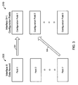
- FIG. 3 is a block diagram to illustrate mapping of returned data fields to a configuration according to some embodiments
- FIG. 4 is a block diagram of a system architecture according to some embodiments.
- FIG. 5 is an illustration of a component model according to some embodiments.
- FIG. 6 is a block diagram illustrating an internal architecture of an administration device according to some embodiments.
- FIGS. 7A and 7B illustrate a flow diagram of process steps according to some embodiments
- FIG. 8 is an outward view of a user interface according to some embodiments.
- FIG. 9 is an outward view of a user interface according to some embodiments.
- FIG. 10 is an outward view of a user interface according to some embodiments.
- FIG. 11 is an outward view of a user interface according to some embodiments.
- FIG. 12 is an outward view of a user interface according to some embodiments.
- FIG. 13 is an outward view of a user interface according to some embodiments.
- FIG. 14 is an outward view of a user interface according to some embodiments.
- FIG. 15 is an outward view of a user interface according to some embodiments.
- FIG. 1 is a block diagram of system 100 according to some embodiments. It should be noted that other architectures may be used in conjunction with other embodiments.
- System 100 includes system 110 and data source 120 .
- System 110 may comprise any system or systems for querying data source 120 and for receiving data therefrom.
- System 110 may be used to aggregate real and/or near-real time operations data arising from the operation of an industrial plant and stored in data source 120 based on a component model.
- a component model may represent tag-based operations data and non-tag-based operations data that are generated by an industrial/mechanical process.
- the operations data may represent any type of operation, including but not limited to batch processes, discrete processes, and/or continuous industrial processes employed in the oil industry (e.g., in an oil refinery), gas industry, and/or chemical industry.
- any industrial process with differing types of operations data may supply data to systems utilizing the invention.
- facilities involved with natural resource refinement and procurement, oil and gas procurement, oil and gas refinement, chemical synthesis and refinement, water treatment, power generation, power transmission, food and beverage processing, raw materials processing (e.g. pulp, lumber, metals, and minerals), agricultural processing and materials processing (e.g. steel mills and foundries) may be suited to utilize platforms and software built upon concepts described herein.
- facilities involved in finished goods manufacturing and production such as product assembly lines may utilize one or more embodiments or systems with such features.
- Operations data may be continuous or discrete and may involve operations data that is presented in batches. Examples include pumps, motors, tanks, pipelines, mills, lathes, mixers, assembly lines, and so on.
- Operations data may include data from machinery, assets, process historians, maintenance systems, enterprise resource planning systems and the like. Examples of such data include pressure, temperature, capacities, volumes, rates of flow, production totals, inventories, performance indicators and the like.
- “Operations data” as used herein includes tag-based point data, non-point data and non-tag-based data.
- point data may be characterized as current, real-time, or value data associated with one or more instruments, components, or portions of a manufacturing, industrial, commercial, or other system. Any of these instruments, components, or portions may be configured to generate, measure, and/or sample point data of interest.
- a data acquisition system for a particular instrument or machine may continuously or periodically acquire data reflecting a motor's operating speed and/or operating temperature as point data from a point data source associated with the motor.
- the point data may be a simple numerical or string value.
- Point data may further be associated with monitoring, control, and reporting functions of various instruments, components, and applications to provide information relating to the operation of a selected system. This information may also be made available for collection and review by various data acquisition and control systems.
- Point data is often acquired in a raw or unstructured form wherein the point data reflects a numerical or string value without supporting details, description, and/or attributes.
- certain types of point data may be associated with real-time or near real-time information (e.g. current temperature, pressure, speed, voltage, current, etc.) that may be desirably sampled, updated or refreshed relatively frequently. The exact frequency of these operations is typically dependent on the characteristics of the point data itself and may be different across the multiple point data sources incorporated into a particular system.
- a tag may therefore represent a data structure comprising selected quanta of information associated with a particular point data informational source and may also comprise certain non-point data.
- acquisition of each tag's current value e.g. point data-associated information
- each tag's attributes e.g. non-point data.
- it is not uncommon for complex industrial automation applications to contain upwards of 100,000 tags it will be appreciated that the individualized configuration and management of tags in the aforementioned manner can be very time consuming, inefficient, and error prone.
- conventional mechanisms for control, monitoring, or archiving of tag-based information tend to become even less useful when attempting to aggregate such information across multiple systems such as in the context of other plant production systems and applications.
- Non-point data may take many forms, including but not limited to, attribute information, parameters, limits and other descriptive information. Certain non-point data may be associated with the point data to provide context thereto. As used herein, the terms point data and non-point data encompass various categories of information that are not necessarily constrained to the examples described herein.
- non-point data may include information such as maintenance work orders (relational data or API (Application Programming Interface) structure data from maintenance systems), equipment documentation (unstructured data usually contained within operating system files and documents), and information such as URL (Uniform Resource Locator) links to supplier web sites.
- maintenance work orders revisional data or API (Application Programming Interface) structure data from maintenance systems
- equipment documentation unstructured data usually contained within operating system files and documents
- URL Uniform Resource Locator
- Data source 120 may comprise any source of any data that may receive queries from system 110 and provide data to system 110 based on the queries.
- System 110 and data source 120 may comprise any number of hardware and/or software elements, some of which are located remote from each other.
- Data of data source 120 may comprise any type of data in any type of data structure that is or becomes known.
- data source 120 comprises a back-end data environment employed in an industrial context.
- Data source 120 may therefore comprise many disparate hardware and software systems, some of which are not interoperational with one another.
- Data source 120 may comprise plant floor production systems, enterprise resource planning data systems, and any other data systems according to some embodiments.
- Data of data source 120 may be associated with any aspect of industrial operations, and may consist of point data as well as non-point data used to characterize, contextualize, or identify the point data and/or the source of the point data.
- FIG. 2 illustrates process steps 200 for describing an operation of system 100 according to some embodiments.
- Process steps 200 may be embodied in one or more software or hardware elements and executed, in whole or in part, by any device or by any number of devices in combination, including but not limited to those devices illustrated in FIG. 1 . Moreover, some or all of process steps 200 may be performed manually.
- Process steps 200 and all other process steps mentioned herein may be embodied in processor-executable process steps read from one or more of a computer-readable medium, such as a floppy disk, a CD-ROM, a DVD-ROM, a ZipTM disk, a magnetic tape, or a signal encoding the process steps, and then stored in a compressed, uncompiled and/or encrypted format.
- a computer-readable medium such as a floppy disk, a CD-ROM, a DVD-ROM, a ZipTM disk, a magnetic tape, or a signal encoding the process steps, and then stored in a compressed, uncompiled and/or encrypted format.
- hard-wired circuitry may be used in place of, or in combination with, processor-executable process steps for implementation of processes according to some embodiments. Thus, embodiments are not limited to any specific combination of hardware and software.
- a first interface is configured to query a data source using a first configuration.
- the first interface is further configured to return a first data set that includes a plurality of records, with each of the plurality of records including data of a plurality of fields.
- FIG. 1 illustrates first interface 125 according to some embodiments of step S 201 .
- First interface 125 may comprise an Application Programming Interface (API) that is exposed by data source 120 and that may be invoked by system 110 .
- API Application Programming Interface
- First interface 125 is associated with a first configuration that may include required and optional field values.
- Configuration of first interface 125 at step S 201 may comprise specifying values for each of the required first configuration and for any desired optional configurations.
- a configuration may comprise structures, class instances, values, tables, and/or any other data types used to constrain an interface.
- a configuration may include “import parameters”, which comprise a structure-like construct used to configure an SAP Business Application Interface (BAPI)® prior to invocation.
- BAPI SAP Business Application Interface
- Step S 201 may also comprise specifying one or more identifiers to associate with one or more fields of first data set 130 .
- First data set 130 comprises a plurality of records that will be returned upon invocation of first interface 125 .
- first data set 130 is illustrated in tabular format, some embodiments employ any currently- or hereafter-known data structure.
- a second interface is configured to query the data source using a second configuration and to return a second data set. At least one field of the second configuration is associated with one of the plurality of fields of the first data set.
- Second interface 135 is configured according to some embodiments of step S 201 .
- Second interface 135 may also comprise an API that is exposed by data source 120 and is invocable by system 110 .
- the second configuration of second interface 135 is associated with a field of first data set 130 as indicated by a dashed line.
- values are specified for all required fields of the second configuration and for any desired optional fields. At least one of the specified values of the second configuration comprises the identifier that was associated with the field as described above with respect to step S 201 .
- Step S 202 may also comprise specifying one or more identifiers to associate with one or more fields of second data set 140 .
- FIG. 3 is a block diagram to illustrate some embodiments of step S 202 .
- Data record 300 represents a record of first data set 130 .
- Configuration 310 represents a second configuration of second interface 135 .
- Arrows 320 and 330 respectively indicate that Configuration Field 1 is associated with Field 1 of first data set 130 , and that Configuration Field 2 is associated with Field 7 .
- the first interface is utilized at step S 203 using the first configuration.
- system 110 may invoke first interface 125 at step S 203 using standardized or proprietary mechanisms.
- first data set 130 is received from data source 120 .
- First data set 130 includes data of the plurality of fields for each record of first data set 130 .
- System 110 associates data of a particular field with the identifier, if any, that was associated with the particular field at step S 201 . Accordingly, if first data set 130 includes three records, system 110 associates three different instances of the identifier with three data values (i.e., one data value per record) of the particular field.
- the second interface is utilized at step S 205 using the second configuration.
- the second configuration includes the data of the field of the first data set that is associated with the second configuration.
- the second interface is may be utilized at step S 205 by invoking the second interface once for each record of the first data set. Since first data set 130 of FIG. 1 includes three records, second interface 135 is invoked three times. Each invocation uses data of a different record, but of the indicated data field.
- a second data set is received from the data source at step S 206 for each utilization of the second interface.
- second interface 135 is invoked three times at step S 205 and system 110 receives a respective second data set 140 for each invocation at step S 206 .
- Each respective second data set 140 may include different data.
- a class-based component model may be populated with data of the respective second data sets at step S 207 .
- System 110 may, for example, populate an object of the class-based component model with the received data.
- the class-based component model may represent tag-based data and non-tag-based data.
- the class-based component model represents assets and geographies of a manufacturing organization, and/or the tag-based data and non-tag-based data are generated by a continuous industrial process.
- the object may include members having member names corresponding to the above-mentioned identifiers. Accordingly, the members are associated with one or more fields of second data set 140 as described above.
- the object may comprise a collection object that includes data of all three second data sets 140 received at step S 206 .
- the object may also include members having member names that are associated with one or more fields of first data set 130 as described above. Accordingly, system 1 may also populated the object with data of first data set 130 .
- FIG. 4 illustrates an architecture of system 400 according to some embodiments. It should be noted that other architectures may be used in conjunction with other embodiments.
- System 400 includes operational data sources 410 in communication with application environment 420 . Also in communication with application environment 420 are administration clients 430 and browsing clients 440 .
- systems “in communication” with one another are directly or indirectly capable of communicating over any number of different systems for transferring data, including but not limited to a local area network, a wide area network, a telephone network, a cellular network, a fiber-optic network, a satellite network, an infrared network, a radio frequency network, and any other type of network that may be used to transmit information between devices.
- communication between systems may proceed over any one or more currently or hereafter-known transmission protocols, such as Asynchronous Transfer Mode (ATM), Internet Protocol (IP), Hypertext Transfer Protocol (HTTP) and Wireless Application Protocol (WAP).
- ATM Asynchronous Transfer Mode
- IP Internet Protocol
- HTTP Hypertext Transfer Protocol
- WAP Wireless Application Protocol
- Operational data sources 410 comprise various data sources, including but not limited to plant floor production systems, enterprise resource planning data systems, and other data systems. Operational data sources 410 may support one or more proprietary interfaces for accessing the data stored therein. An example of such an interface according to some embodiments is an SAPTM Business Application Interface. Operational data sources 410 may also provide one or more non-proprietary mechanism for accessing stored data. The stored data may represent any type of operation, including but not limited to continuous industrial processes employed in the oil, gas, and/or chemical industries.
- Application environment 420 may transmit queries for data to operational data sources 410 .
- operational data sources 410 acquire and transmit the data to application environment 420 .
- An example of this operation according to some embodiments is illustrated in FIG. 1 and described above with respect to FIG. 2 .
- the operation of system 400 according to some embodiments of process steps 200 will be described below with respect to FIGS. 7A and 7B .
- Application environment 420 may comprise enterprise server 422 , Web server 424 , solution server 426 , and data store 428 .
- Application environment 420 may comprise a single server device or multiple devices.
- enterprise server 422 and solution server 426 comprise application programs developed in Java and/or C++ and running under Windows XP/NT/2000/2003.
- Web server 424 manages data communication between application environment 420 , administration clients 430 , and browsing clients 440 .
- One or more administration clients 430 and browsing clients 440 may execute one or more Java applets to interact with Java servlets of Web server 424 according to some embodiments.
- Solution server 426 is used to access data from operational data sources 410 .
- solution server 426 includes connection groups and connection processes.
- a connection group includes one or more object instances, each of which is associated with a particular data source of operational data sources 410 .
- Different connection groups are associated with different data sources.
- a connection process comprises processor-executable process steps to retrieve data from a particular type of data source (e.g., an SAP R/3TM server).
- a connection process may comply with standard or proprietary protocols, including but not limited to ODBC, JDBC, OPC DA, OPC HDA, OPC AE, and Web Services.
- Process steps to retrieve data from a particular type of data source may be provided in a library by an owner of a proprietary interface for accessing the particular type of data source.
- connection groups may use a same connection process to access their respective data sources.
- each object instance includes scripts (e.g. Structured Query Language scripts) to populate itself based on retrieved data.
- Solution server 426 manages the objects, connection groups and connection processes to access data that is acquired and stored by disparate systems of operational data sources 410 .
- Solution server 426 may transmit the data acquired from operational data sources 410 to data store 450 for storage according to some embodiments.
- Data store 450 may store any data used during the operation of application environment 420 .
- Data may be stored in data store 450 according to any currently- or hereafter-known protocol for storing data, including but not limited to a class-based component and view model.
- Data store 450 may comprise a front-end application that is usable to access and/or manage the data stored therein. Such a front-end application may support Structured Query Language commands or the like.
- data store 450 may receive data directly from operational data sources 410 .
- Administration clients 430 may provide user interfaces to perform administration functions for operating system 400 . For example, an administrator may manipulate a user interface displayed by one of administration clients 430 to configure a first interface and a second interface as described with respect to process steps 200 . Information received by the user interfaces may be received by Web server 424 and transmitted to data store 428 . Examples of administration clients 430 according to some embodiments include but are not limited to a desktop computer, a laptop computer, a computer terminal, a personal digital assistant, a telephone, and a tablet computer.
- Browsing clients 440 may present views of data contained in data store 428 . Such views may include real or near-real time data and may include data stored in data store 428 in an object-oriented format. Browsing clients 440 may provide any suitable client application such as a Web browser or a Java applet. As such, a browsing client 440 may be connected to application environment 420 through the Internet or through an Intranet. Browsing clients 40 may comprise any suitable user devices, including but not limited to those mentioned above with respect to administration clients 430 .
- the elements of FIG. 4 are connected differently than as shown, and each block shown is implemented by one or more hardware and software elements.
- the hardware and software elements of one or more blocks may be located remotely from each other. Some embodiments may include environments, systems, servers, and clients that are different from those shown.
- FIG. 5 illustrates component model 500 according to some embodiments.
- Application environment 420 may store and manage component model 500 to represent tag-based data and non-tag-based data that are generated by a continuous industrial process.
- data store 428 stores data in the form of objects instantiated based on components of component model 500 .
- the tag-based data may be generated by and received from SCADA, HMI, DCS, plant historians, etc.
- the non-tag-based data may be generated by and received from business systems and applications (e.g., SAP (ERP), Oracle Manufacturing Apps, general database apps, etc).
- component model 500 may represent assets and geographies of a plant or manufacturing organization.
- Commonly-assigned U.S. Pat. No. 6,700,590 describes a system to use a class-based object and view model to collect and display data received from multiple heterogeneous sources.
- This system encapsulates received tag-based data and non-tag-based data as objects, which are instantiations of defined components.
- the use of components and objects may provide reusability, consistency, inheritance and other benefits known to those familiar with object-oriented techniques.
- Component model 500 may be established and utilized in any manner, including but not limited to those specified in aforementioned U.S. Pat. No. 6,700,590 and/or U.S. Patent Application Publication No. 2005/0144154, the contents of which are herein incorporated by reference for all purposes.
- Component model 500 may follow any suitable modeling protocol or format; including those mentioned in the foregoing references.
- Each component of component model 500 includes at least one member, and each component member is associated with a member type.
- a member of a first component may be a second component, in which case the associated member type is the name of the second component. All members that are associated with “primitive” member types (which include anything other than another component) are either associated with a tag attribute or not (i.e. “None”).
- Component model 500 of FIG. 5 is shown in a tree or hierarchical format which facilitates visualization and understanding of the relationships and patterns of inheritance/instantiations for the various component definitions of FIG. 5 .
- Component model 500 may therefore be displayed to an administrator or user according to some embodiments. In the illustrated embodiment, only components whose members are not associated with tag attributes are displayed in component model 500 .
- FIG. 6 is a block diagram of an internal architecture of administration client 430 according to some embodiments.
- Administration device 430 may operate to configure a first interface to query one of operational data sources 410 using a first configuration and to return a first data set including a plurality of records, with each of the plurality of records comprising data of a plurality of fields.
- Administration device 430 may further operate to configure a second interface to query the data source using a second configuration and to return a second data set, wherein at least one field of the second configuration is associated with one of the plurality of fields.
- Administration device 430 includes microprocessor 431 in communication with communication bus 432 .
- Microprocessor 431 may comprise an Intel ItaniumTM microprocessor or other type of processor and is used to execute processor-executable process steps so as to control the elements of administration device 430 to provide desired functionality.
- Network interface 433 is used to transmit data to and to receive data from devices external to administration device 430 such as a device housing Web server 424 .
- Network interface 433 is therefore preferably configured with hardware suitable to physically interface with desired external devices and/or network connections.
- network interface 433 may comprise an Ethernet connection to a local area network through which administration device 430 may receive and transmit information over the Web.
- Input device 434 and display 435 are also in communication with communication bus 432 .
- Any known input device may comprise input device 434 , including a keyboard, mouse, touch pad, voice-recognition system, or any combination of these devices.
- information may also be input to administration device 430 via network interface 433 .
- Display 435 may be an integral or separate CRT display, flat-panel display or the like used to present graphics and text in response to commands issued by microprocessor 431 .
- display 435 displays user interfaces that may be manipulated by an administrator using input device 434 to configure a first interface and a second interface as mentioned above. Some examples of such user interfaces are described below.
- RAM 436 is connected to communication bus 432 to provide microprocessor 431 with fast data storage and retrieval.
- processor-executable process steps being executed by microprocessor 431 are typically stored temporarily in RAM 436 and executed therefrom by microprocessor 431 .
- ROM 437 provides storage from which data can be retrieved but to which data cannot be stored. Accordingly, ROM 437 may be used to store invariant process steps and other data, such as basic input/output instructions and data used during boot-up of administration device 430 or to control network interface 433 .
- RAM 436 and ROM 437 may communicate directly with microprocessor 431 instead of over communication bus 432 .
- Data storage device 438 stores, among other data, processor-executable process steps of operations data administrator application 4382 .
- Administration device 430 may execute process steps of operations data administrator application 4382 to provide the functions attributed herein to administrator device 430 .
- Operations data administrator application 4382 may comprise a Java applet or a standalone application suitable for the operating system of administration device 4382 .
- Web browser 4384 may comprise processor-executable process steps of a Web client. As such, administration device 430 may execute process steps of Web browser 4384 to request and receive Web pages from a Web server such as Web server 424 .
- a Java applet such as operations data administrator application 4382 may execute within an execution engine provided by Web browser 4384 .
- Data storage device 438 also includes processor-executable process steps of other applications 4386 .
- Other applications 4386 may include process steps to perform calendaring, e-mail functions, word processing, accounting, presentation development and the like.
- Data storage device 438 may also store process steps of an operating system (unshown).
- An operating system provides a platform for executing applications, device drivers and other process steps that interact with elements of administration device 430 .
- Data files 4388 may include any electronic files usable by any application of administration device 430 .
- FIGS. 7A and 7B illustrate process steps 700 according to some embodiments.
- Process steps 700 may be embodied in one or more software or hardware elements and executed, in whole or in part, by any device or by any number of devices in combination, including by application environment 420 .
- a component to store data is defined.
- the data is returned by a first interface and one or more next interfaces as will be described below.
- the component may comply with a class-based component and view model such as that described in above-mentioned U.S. Pat. No. 6,700,590, but embodiments are not limited thereto.
- the component may comprise a class from which one or more objects may be instantiated as is known in object-oriented programming.
- the component may be defined in any suitable manner that is or becomes known. According to some embodiments, an administrator operates input device 434 of administration client 430 to specify a component name and one or more members of the component. In the example below, the defined component includes members that may be used to determine a cost of a particular type of inventoried material. The defined component may include scripts to populate itself based on retrieved data, and may be added to a component model such as component model 500 of FIG. 5 .
- a data source is selected in step S 702 .
- the selected data source is to be queried using the first and next interfaces.
- the data source may comprise any system for storing data.
- the selected data source supports proprietary interfaces for accessing the data stored therein.
- the data source may be selected at step S 702 by selecting a connection process and/or a connection group.
- a connection process may be associated with one or more connection groups.
- FIG. 8 is an outward view of user interface 800 that may be used in conjunction with some embodiments of step S 702 .
- User interface 800 may be presented to an administrator on display 435 of administration client 430 . More specifically, administration client 430 may execute operations data administrator application 4382 to request access to a configuration utility served by application environment 420 . In some embodiments, administration client 430 executes Web browser 4384 to request access from Web server 424 of application environment 420 .
- Application environment 420 may perform any required authentication and/or security checks before transmitting user interface 800 (e.g., as a Web page) to administration client 430 .
- user interface 800 e.g., as a Web page
- Embodiments are not limited to the function, appearance or arrangement of the user interfaces described herein.
- connection group field 810 for specifying a connection group (and a respective data source) to query.
- the connection group is associated with a data source and also with a connector process for accessing the data source.
- the connector process may comprise proprietary process steps usable to invoke proprietary interfaces supported by the data source.
- the proprietary process may be provided in a library (e.g., a Java Connector library) available to application environment 240 .
- User interface 800 also includes component area 820 for displaying a component model.
- the component model is expanded to present the component “chaining component” defined in step S 701 .
- the component has been selected, and therefore its members are presented in Mappings table 830 of interface 800 . Also displayed are data types associated with each member.
- a first interface is selected in step S 703 .
- the first interface may comprise an API that is exposed by the selected data source and that may be invoked by application environment 420 .
- the first interface is to query the selected data source using the first configuration.
- the first interface is also to return a first data set that includes a plurality of records, with each of the plurality of records including data of a plurality of fields.
- the first interface is selected in the present example by populating function name field 840 with a name of the first interface.
- Configuration table 850 shows the first configuration of the first interface. One or more of fields of the configuration may be required as specified in table 850 . Table 850 also presents a data type associated with each field of the configuration and allows entry of a value for each field of the configuration.
- Input tables table 850 displays information related to any input tables of the first interface.
- the configuration of the selected first interface does not include any input tables.
- Some configurations may include both import parameters and input tables, and other configurations may include only input tables. Any type of data structure may be used as input to an interface according to some embodiments.
- an administrator selects a data structure to query using the first interface.
- the first interface is capable of querying a particular set of tables. These tables are listed by and selectable via pull-down menu 870 .
- One or more members of the selected component are mapped to one or more return data fields of the first interface at step S 705 .
- the return data fields comprise fields of each record that is returned by the first interface.
- the administrator first selects an empty field in the Column Name column of table 830 .
- FIG. 9 is a view of user interface 800 after selection of the empty field. As shown, a pull-down menu is displayed including names of the return data fields associated with the first interface. The empty field may be populated by selecting one of the displayed names.
- FIG. 10 is a view of interface 800 after mapping two members of the component to two return data fields of the first interface.
- steps S 706 may comprise assigning values to one or more fields of the first configuration of the first interface.
- the administrator selects a field in the Value column of table 850 and is presented with a window as shown in FIG. 11 .
- Window 1100 is associated with the selected field. Window 1100 allows the administrator to specify values of data structure members associated with the field. After specifying the values and selecting OK icon 1110 , the field of table 850 is populated with the specified values as shown in FIG. 12 .
- a next interface supported by the data source is selected at step S 707 .
- the next interface may correspond to second interface 135 of FIG. 1 .
- the administrator selects Chaining checkbox 1200 in step S 707 as shown in FIG. 12 .
- Window 1300 of FIG. 1300 is displayed as a result of the selection.
- the name of the next interface may be specified in field 1310 of window 1300 .
- the next interface may also be supported by the selected data source and invoked by application environment 420 .
- the administrator selects a data structure to query using the next interface at step S 708 .
- the data structure may be selected via pull-down menu 1320 .
- pull-down menu 1320 may list a particular set of tables that may be queried using next interface.
- a configuration of the next interface is defined at step S 709 .
- at least one field of the defined configuration is associated with one of the returned data fields of the previous (i.e. first) interface.
- Import parameters table 1330 lists import parameters of the next interface, along with a data type of each parameter and an indication of whether each parameter is optional or required. According to the present example, the selected next interface is not associated with any input tables.
- the administrator may input values for one or more of the import parameters in the Value column of table 1330 .
- the values may comprise dates, strings, numbers or any suitable data type.
- An input value for a particular import parameter may also comprise a member name of the component defined in step S 701 .
- the member name is associated with a returned data field of the first interface as shown in table 830 . Accordingly, the particular import parameter (i.e., field of the configuration) is associated with the returned data field.
- One or more members of the selected component are mapped to one or more return data fields of the next interface at step S 710 .
- the return data fields comprise fields of each record that is returned by the next interface.
- the administrator performs this mapping by first selecting an empty field in the Column Name column of table 830 .
- FIG. 14 illustrates user interface 800 after selection of the empty field of table 830 that is associated with the INVENTORY_PRICE component member. As shown, a pull-down menu is displayed including names of the return data fields associated with the first interface and the return data fields associated with the next interface. The administrator may populate the empty field by selecting one of the displayed names.
- FIG. 15 is a view of interface 800 after mapping a return data field of the next interface to the INVENTORY_PRICE component member.
- Some embodiments allow the administrator to configure additional interfaces for the present interface chain. Accordingly, it is determined at step S 711 whether additional interfaces are to be configured. If so, flow returns to step S 711 for selection of a next interface. Flow then continues as described above. For example, a configuration of the next interface is defined at step S 709 , with at least one field of the defined configuration being associated with one of the returned data fields of the prior “next” (i.e., second) interface. One or more of the fields may also be associated with one of the returned data fields of the first interface. Flow proceeds to step S 712 if no further interfaces are to be configured.
- the first interface is utilized using the first configuration at step S 712 .
- Application environment 420 may execute proprietary process steps of a connector process at step S 712 to invoke first interface at step S 712 .
- Data is received from the data source at step S 713 in response to the utilization.
- the received data comprises a plurality of records.
- Each record includes data for a plurality of fields such as those illustrated in the pull-down field of table 830 shown in FIG. 9 .
- data of a particular field may be associated with the component member that was mapped to the field at step S 705 .
- the next interface is invoked at step S 714 using the configuration of the next interface.
- At least one field of the configuration includes data of a returned data field that was associated with the at least one field at step S 709 .
- the next interface is invoked for only one record of the received data.
- Next data is received from the data source at step S 715 in response to the invocation of the next interface. Since the data received in step S 713 may include a plurality of records, it is determined at step S 716 whether the data received in step S 713 includes any additional records. If so, the next interface is again invoked using data of a next record received in step S 713 . Flow therefore cycles between steps S 714 through S 716 for each record of the received data.
- step S 717 it is determined whether additional interfaces were defined during iterations of steps S 707 through S 710 . If so, flow returns to step S 714 and continues as described above. Steps S 714 through S 716 are therefore executed with respect to an additional interface for each record received in response to invocation of a previous interface. Interface 145 and data set 150 of FIG. 1 illustrate such an additional interface and received data according to some embodiments.
- step S 717 Flow continues from step S 717 to step S 718 if the determination at step S 717 is negative.
- the component defined at step S 701 is populated at step S 718 .
- Application environment 420 may populate the component by instantiating an object or a collection object (e.g., a table of two or more objects) and by populating the object or collection with the data received during each performance of steps S 713 and S 715 .
- the object members may be associated with the received data based on the mappings defined at steps S 705 and S 710 .
- Steps S 701 through S 711 were described above as being executed by an administrator in conjunction with administration client 430 .
- One or more of steps S 701 through S 711 may be performed by one or more administration clients 430 or other devices.
- Steps S 701 through S 711 may also be viewed as being performed by application environment 420 in response to input received from administration client 430 .
Abstract
Description
Claims (26)
Priority Applications (1)
| Application Number | Priority Date | Filing Date | Title |
|---|---|---|---|
| US11/220,882 US8700559B2 (en) | 2005-03-28 | 2005-09-06 | Interface chaining to populate a class-based model |
Applications Claiming Priority (2)
| Application Number | Priority Date | Filing Date | Title |
|---|---|---|---|
| US66603205P | 2005-03-28 | 2005-03-28 | |
| US11/220,882 US8700559B2 (en) | 2005-03-28 | 2005-09-06 | Interface chaining to populate a class-based model |
Publications (2)
| Publication Number | Publication Date |
|---|---|
| US20060218131A1 US20060218131A1 (en) | 2006-09-28 |
| US8700559B2 true US8700559B2 (en) | 2014-04-15 |
Family
ID=37036399
Family Applications (1)
| Application Number | Title | Priority Date | Filing Date |
|---|---|---|---|
| US11/220,882 Active 2029-11-12 US8700559B2 (en) | 2005-03-28 | 2005-09-06 | Interface chaining to populate a class-based model |
Country Status (1)
| Country | Link |
|---|---|
| US (1) | US8700559B2 (en) |
Cited By (1)
| Publication number | Priority date | Publication date | Assignee | Title |
|---|---|---|---|---|
| US10318904B2 (en) | 2016-05-06 | 2019-06-11 | General Electric Company | Computing system to control the use of physical state attainment of assets to meet temporal performance criteria |
Families Citing this family (9)
| Publication number | Priority date | Publication date | Assignee | Title |
|---|---|---|---|---|
| US6700590B1 (en) * | 1999-11-01 | 2004-03-02 | Indx Software Corporation | System and method for retrieving and presenting data using class-based component and view model |
| US7689579B2 (en) * | 2003-12-03 | 2010-03-30 | Siemens Aktiengesellschaft | Tag modeling within a decision, support, and reporting environment |
| US7840607B2 (en) * | 2004-08-06 | 2010-11-23 | Siemens Aktiengesellschaft | Data mart generation and use in association with an operations intelligence platform |
| US8700671B2 (en) | 2004-08-18 | 2014-04-15 | Siemens Aktiengesellschaft | System and methods for dynamic generation of point / tag configurations |
| US7814123B2 (en) * | 2004-12-02 | 2010-10-12 | Siemens Aktiengesellschaft | Management of component members using tag attributes |
| US8442938B2 (en) | 2005-01-14 | 2013-05-14 | Siemens Aktiengesellschaft | Child data structure update in data management system |
| US20060218116A1 (en) * | 2005-03-28 | 2006-09-28 | O'hearn James E | Pass-through interface queries to populate a class-based model |
| US8260783B2 (en) | 2007-02-27 | 2012-09-04 | Siemens Aktiengesellschaft | Storage of multiple, related time-series data streams |
| US20150293530A1 (en) * | 2014-02-28 | 2015-10-15 | Invensys Systems, Inc. | Manufacturing execution system authorization |
Citations (57)
| Publication number | Priority date | Publication date | Assignee | Title |
|---|---|---|---|---|
| US5487141A (en) | 1994-01-21 | 1996-01-23 | Borland International, Inc. | Development system with methods for visual inheritance and improved object reusability |
| US5519866A (en) | 1993-06-28 | 1996-05-21 | Taligent, Inc. | Method and apparatus of incrementally linking components of a modeled computer program |
| US5566330A (en) | 1991-08-20 | 1996-10-15 | Powersoft Corporation | Method for forming a reusable and modifiable database interface object |
| US5632022A (en) | 1991-11-13 | 1997-05-20 | The United States Of America As Represented By The Administrator Of The National Aeronautics And Space Administration | Encyclopedia of software components |
| US5764226A (en) | 1995-12-29 | 1998-06-09 | International Business Machine Corp. | Reusable and modifiable data entry interface part |
| US5787283A (en) | 1995-10-27 | 1998-07-28 | International Business Machines Corporation | Framework for manufacturing logistics decision support |
| US5864862A (en) | 1996-09-30 | 1999-01-26 | Telefonaktiebolaget Lm Ericsson (Publ) | System and method for creating reusable components in an object-oriented programming environment |
| US5945944A (en) | 1996-03-08 | 1999-08-31 | Snaptrack, Inc. | Method and apparatus for determining time for GPS receivers |
| US5980096A (en) | 1995-01-17 | 1999-11-09 | Intertech Ventures, Ltd. | Computer-based system, methods and graphical interface for information storage, modeling and stimulation of complex systems |
| US5982362A (en) | 1996-05-30 | 1999-11-09 | Control Technology Corporation | Video interface architecture for programmable industrial control systems |
| US5991534A (en) | 1997-06-03 | 1999-11-23 | Sun Microsystems, Inc. | Method and apparatus for editing a software component |
| US6061573A (en) | 1997-02-21 | 2000-05-09 | Motorola, Inc. | Method and apparatus in a radio communication system for synchronizing transmissions while maintaining full user traffic |
| US6198480B1 (en) | 1998-10-07 | 2001-03-06 | Wonderware Corporation | Object-oriented tag browser |
| US6204808B1 (en) | 1998-08-13 | 2001-03-20 | Ericsson Inc. | Method and system for aiding GPS receivers via a cellular or PCS network |
| US6208871B1 (en) | 1998-02-27 | 2001-03-27 | Motorola, Inc. | Method and apparatus for providing a time adjustment to a wireless communication system |
| US6223182B1 (en) | 1998-06-30 | 2001-04-24 | Oracle Corporation | Dynamic data organization |
| US20010001851A1 (en) | 1998-09-15 | 2001-05-24 | Piety Kenneth R. | Database wizard |
| US6336138B1 (en) | 1998-08-25 | 2002-01-01 | Hewlett-Packard Company | Template-driven approach for generating models on network services |
| US6381605B1 (en) | 1999-05-29 | 2002-04-30 | Oracle Corporation | Heirarchical indexing of multi-attribute data by sorting, dividing and storing subsets |
| US6429882B1 (en) | 1999-03-15 | 2002-08-06 | Sun Microsystems, Inc. | User interface component |
| US6430415B1 (en) | 1999-03-29 | 2002-08-06 | Qualcomm Incorporated | Method and apparatus for locating GPS equipped wireless devices operating in analog mode |
| US6463352B1 (en) | 1999-01-21 | 2002-10-08 | Amada Cutting Technologies, Inc. | System for management of cutting machines |
| US6490719B1 (en) | 1999-07-26 | 2002-12-03 | Gary Thomas | System and method for configuring and executing a flexible computer program comprising component structures |
| US20020184610A1 (en) | 2001-01-22 | 2002-12-05 | Kelvin Chong | System and method for building multi-modal and multi-channel applications |
| US20020186248A1 (en) | 2001-06-08 | 2002-12-12 | Venkatesh Ramanathan | Method and apparatus for pattern based generation of graphical user interfaces (GUI) |
| US20030020703A1 (en) | 1997-08-25 | 2003-01-30 | Holub Richard A. | System for distributing and controlling color reproduction at multiple sites |
| US20030058277A1 (en) | 1999-08-31 | 2003-03-27 | Bowman-Amuah Michel K. | A view configurer in a presentation services patterns enviroment |
| US6543046B1 (en) | 1995-07-20 | 2003-04-01 | Accenture Llp | Apparatus and method for navigating objects within a computer-implemented object environment |
| US20030084190A1 (en) | 2001-10-25 | 2003-05-01 | Kimball Robert H. | Apparatus and system for maintaining accurate time in a wireless environment |
| US20030139968A1 (en) | 2002-01-11 | 2003-07-24 | Ebert Peter S. | Context-aware and real-time tracking |
| WO2003062934A1 (en) | 2002-01-18 | 2003-07-31 | Lockheed Martin Corporation | Object oriented framework architecture for sensing and/or control environments |
| US6609123B1 (en) | 1999-09-03 | 2003-08-19 | Cognos Incorporated | Query engine and method for querying data using metadata model |
| US20030163329A1 (en) | 1999-09-21 | 2003-08-28 | David Bolene | Method for defining an executable business model |
| US20040032836A1 (en) | 2001-07-09 | 2004-02-19 | Francesco Grilli | Method and apparatus for time-aligning transmissions from multiple base stations in a CDMA communication system |
| US20040036716A1 (en) | 2002-06-12 | 2004-02-26 | Jordahl Jena J. | Data storage, retrieval, manipulation and display tools enabling multiple hierarchical points of view |
| US6700590B1 (en) | 1999-11-01 | 2004-03-02 | Indx Software Corporation | System and method for retrieving and presenting data using class-based component and view model |
| US6788249B1 (en) | 2003-07-23 | 2004-09-07 | Snaptrack Incorporated | System for setting coarse GPS time in a mobile station within an asynchronous wireless network |
| US20040190378A1 (en) | 2003-03-27 | 2004-09-30 | Dominic Farmer | Virtual real-time clock based on time information from multiple communication systems |
| US20050044097A1 (en) | 2003-08-19 | 2005-02-24 | Jaime Singson | Method and apparatus for facilitating data stewardship for metadata in an ETL and data warehouse system |
| US20050071749A1 (en) | 2003-09-30 | 2005-03-31 | Bjoern Goerke | Developing and using user interfaces with views |
| US20050144154A1 (en) * | 2003-12-03 | 2005-06-30 | Indx Software Corporatin, A Siemens Company | Tag management within a decision, support, and reporting environment |
| US20050146462A1 (en) | 2003-11-07 | 2005-07-07 | Charles Abraham | Method and apparatus for managing time in a satellite positioning system |
| US20050172306A1 (en) | 2003-10-20 | 2005-08-04 | Agarwal Manoj K. | Systems, methods and computer programs for determining dependencies between logical components in a data processing system or network |
| US20050182709A1 (en) | 1999-02-05 | 2005-08-18 | Babcock & Brown Lp, A Delaware Limited Partnership | Automated financial scenario modeling and analysis tool having an intelligent graphical user interface |
| US20050216555A1 (en) | 2003-12-23 | 2005-09-29 | English Arthur V | Platform independent model-based framework for exchanging information in the justice system |
| US20050246627A1 (en) | 2004-02-17 | 2005-11-03 | Sayed Omar F | System and method for creating and maintaining a web site |
| US6996566B1 (en) | 2000-11-21 | 2006-02-07 | International Business Machines Corporation | Method and system for an object model with embedded metadata and mapping information |
| US7006036B2 (en) | 2002-08-02 | 2006-02-28 | Qualcomm Incorporated | Apparatus and method for time maintenance in a satellite position system receiver |
| US20060067334A1 (en) * | 2004-08-18 | 2006-03-30 | Ougarov Andrei V | System and methods for dynamic generation of point / tag configurations |
| US20060116994A1 (en) | 2004-11-30 | 2006-06-01 | Oculus Info Inc. | System and method for interactive multi-dimensional visual representation of information content and properties |
| US20060123019A1 (en) * | 2004-12-02 | 2006-06-08 | Nguyen Thomas N | Management of component members using tag attributes |
| US20060218116A1 (en) | 2005-03-28 | 2006-09-28 | O'hearn James E | Pass-through interface queries to populate a class-based model |
| US20060294199A1 (en) | 2005-06-24 | 2006-12-28 | The Zeppo Network, Inc. | Systems and Methods for Providing A Foundational Web Platform |
| US20070124209A1 (en) | 1998-03-27 | 2007-05-31 | Walker Jay S | System and method for tracking and establishing a progressive discount based upon a customer's visits to a retail establishment |
| US20070208574A1 (en) | 2002-06-27 | 2007-09-06 | Zhiyu Zheng | System and method for managing master data information in an enterprise system |
| US20080103786A1 (en) | 2006-10-31 | 2008-05-01 | Liang-Jie Zhang | Method and Apparatus for Representing and Configuring Flexible and Extensible Presentation Patterns |
| US20100223296A1 (en) | 1998-09-04 | 2010-09-02 | Kalido Limited | Data Processing System |
-
2005
- 2005-09-06 US US11/220,882 patent/US8700559B2/en active Active
Patent Citations (64)
| Publication number | Priority date | Publication date | Assignee | Title |
|---|---|---|---|---|
| US5566330A (en) | 1991-08-20 | 1996-10-15 | Powersoft Corporation | Method for forming a reusable and modifiable database interface object |
| US5632022A (en) | 1991-11-13 | 1997-05-20 | The United States Of America As Represented By The Administrator Of The National Aeronautics And Space Administration | Encyclopedia of software components |
| US5519866A (en) | 1993-06-28 | 1996-05-21 | Taligent, Inc. | Method and apparatus of incrementally linking components of a modeled computer program |
| US5487141A (en) | 1994-01-21 | 1996-01-23 | Borland International, Inc. | Development system with methods for visual inheritance and improved object reusability |
| US5980096A (en) | 1995-01-17 | 1999-11-09 | Intertech Ventures, Ltd. | Computer-based system, methods and graphical interface for information storage, modeling and stimulation of complex systems |
| US6543046B1 (en) | 1995-07-20 | 2003-04-01 | Accenture Llp | Apparatus and method for navigating objects within a computer-implemented object environment |
| US5787283A (en) | 1995-10-27 | 1998-07-28 | International Business Machines Corporation | Framework for manufacturing logistics decision support |
| US5764226A (en) | 1995-12-29 | 1998-06-09 | International Business Machine Corp. | Reusable and modifiable data entry interface part |
| US5945944A (en) | 1996-03-08 | 1999-08-31 | Snaptrack, Inc. | Method and apparatus for determining time for GPS receivers |
| US5982362A (en) | 1996-05-30 | 1999-11-09 | Control Technology Corporation | Video interface architecture for programmable industrial control systems |
| US5864862A (en) | 1996-09-30 | 1999-01-26 | Telefonaktiebolaget Lm Ericsson (Publ) | System and method for creating reusable components in an object-oriented programming environment |
| US6061573A (en) | 1997-02-21 | 2000-05-09 | Motorola, Inc. | Method and apparatus in a radio communication system for synchronizing transmissions while maintaining full user traffic |
| US5991534A (en) | 1997-06-03 | 1999-11-23 | Sun Microsystems, Inc. | Method and apparatus for editing a software component |
| US20030020703A1 (en) | 1997-08-25 | 2003-01-30 | Holub Richard A. | System for distributing and controlling color reproduction at multiple sites |
| US6208871B1 (en) | 1998-02-27 | 2001-03-27 | Motorola, Inc. | Method and apparatus for providing a time adjustment to a wireless communication system |
| US20070124209A1 (en) | 1998-03-27 | 2007-05-31 | Walker Jay S | System and method for tracking and establishing a progressive discount based upon a customer's visits to a retail establishment |
| US6223182B1 (en) | 1998-06-30 | 2001-04-24 | Oracle Corporation | Dynamic data organization |
| US6204808B1 (en) | 1998-08-13 | 2001-03-20 | Ericsson Inc. | Method and system for aiding GPS receivers via a cellular or PCS network |
| US6336138B1 (en) | 1998-08-25 | 2002-01-01 | Hewlett-Packard Company | Template-driven approach for generating models on network services |
| US20100223296A1 (en) | 1998-09-04 | 2010-09-02 | Kalido Limited | Data Processing System |
| US20010001851A1 (en) | 1998-09-15 | 2001-05-24 | Piety Kenneth R. | Database wizard |
| US6198480B1 (en) | 1998-10-07 | 2001-03-06 | Wonderware Corporation | Object-oriented tag browser |
| US6463352B1 (en) | 1999-01-21 | 2002-10-08 | Amada Cutting Technologies, Inc. | System for management of cutting machines |
| US20050182709A1 (en) | 1999-02-05 | 2005-08-18 | Babcock & Brown Lp, A Delaware Limited Partnership | Automated financial scenario modeling and analysis tool having an intelligent graphical user interface |
| US6429882B1 (en) | 1999-03-15 | 2002-08-06 | Sun Microsystems, Inc. | User interface component |
| US6430415B1 (en) | 1999-03-29 | 2002-08-06 | Qualcomm Incorporated | Method and apparatus for locating GPS equipped wireless devices operating in analog mode |
| US6505205B1 (en) | 1999-05-29 | 2003-01-07 | Oracle Corporation | Relational database system for storing nodes of a hierarchical index of multi-dimensional data in a first module and metadata regarding the index in a second module |
| US6381605B1 (en) | 1999-05-29 | 2002-04-30 | Oracle Corporation | Heirarchical indexing of multi-attribute data by sorting, dividing and storing subsets |
| US6490719B1 (en) | 1999-07-26 | 2002-12-03 | Gary Thomas | System and method for configuring and executing a flexible computer program comprising component structures |
| US20030058277A1 (en) | 1999-08-31 | 2003-03-27 | Bowman-Amuah Michel K. | A view configurer in a presentation services patterns enviroment |
| US6609123B1 (en) | 1999-09-03 | 2003-08-19 | Cognos Incorporated | Query engine and method for querying data using metadata model |
| US20030163329A1 (en) | 1999-09-21 | 2003-08-28 | David Bolene | Method for defining an executable business model |
| US7069514B2 (en) | 1999-11-01 | 2006-06-27 | Indx Software Corp. | Modeling system for retrieving and displaying data from multiple sources |
| US20060200741A1 (en) | 1999-11-01 | 2006-09-07 | Demesa Jesse G | Modeling system for retrieving and displaying data from multiple sources |
| US6700590B1 (en) | 1999-11-01 | 2004-03-02 | Indx Software Corporation | System and method for retrieving and presenting data using class-based component and view model |
| US20040117393A1 (en) | 1999-11-01 | 2004-06-17 | Demesa Jesse G | Modeling system for retrieving and displaying data from multiple sources |
| US6996566B1 (en) | 2000-11-21 | 2006-02-07 | International Business Machines Corporation | Method and system for an object model with embedded metadata and mapping information |
| US20020184610A1 (en) | 2001-01-22 | 2002-12-05 | Kelvin Chong | System and method for building multi-modal and multi-channel applications |
| US20020186248A1 (en) | 2001-06-08 | 2002-12-12 | Venkatesh Ramanathan | Method and apparatus for pattern based generation of graphical user interfaces (GUI) |
| US20040032836A1 (en) | 2001-07-09 | 2004-02-19 | Francesco Grilli | Method and apparatus for time-aligning transmissions from multiple base stations in a CDMA communication system |
| US20030084190A1 (en) | 2001-10-25 | 2003-05-01 | Kimball Robert H. | Apparatus and system for maintaining accurate time in a wireless environment |
| US20030139968A1 (en) | 2002-01-11 | 2003-07-24 | Ebert Peter S. | Context-aware and real-time tracking |
| WO2003062934A1 (en) | 2002-01-18 | 2003-07-31 | Lockheed Martin Corporation | Object oriented framework architecture for sensing and/or control environments |
| US20040036716A1 (en) | 2002-06-12 | 2004-02-26 | Jordahl Jena J. | Data storage, retrieval, manipulation and display tools enabling multiple hierarchical points of view |
| US20070239741A1 (en) | 2002-06-12 | 2007-10-11 | Jordahl Jena J | Data storage, retrieval, manipulation and display tools enabling multiple hierarchical points of view |
| US20070208574A1 (en) | 2002-06-27 | 2007-09-06 | Zhiyu Zheng | System and method for managing master data information in an enterprise system |
| US7006036B2 (en) | 2002-08-02 | 2006-02-28 | Qualcomm Incorporated | Apparatus and method for time maintenance in a satellite position system receiver |
| US20080018530A1 (en) | 2003-03-27 | 2008-01-24 | Dominic Farmer | Virtual real-time clock based on time information from multiple communication systems |
| US20040190378A1 (en) | 2003-03-27 | 2004-09-30 | Dominic Farmer | Virtual real-time clock based on time information from multiple communication systems |
| US6788249B1 (en) | 2003-07-23 | 2004-09-07 | Snaptrack Incorporated | System for setting coarse GPS time in a mobile station within an asynchronous wireless network |
| US20050044097A1 (en) | 2003-08-19 | 2005-02-24 | Jaime Singson | Method and apparatus for facilitating data stewardship for metadata in an ETL and data warehouse system |
| US20050071749A1 (en) | 2003-09-30 | 2005-03-31 | Bjoern Goerke | Developing and using user interfaces with views |
| US20050172306A1 (en) | 2003-10-20 | 2005-08-04 | Agarwal Manoj K. | Systems, methods and computer programs for determining dependencies between logical components in a data processing system or network |
| US20050146462A1 (en) | 2003-11-07 | 2005-07-07 | Charles Abraham | Method and apparatus for managing time in a satellite positioning system |
| US20050143969A1 (en) | 2003-12-03 | 2005-06-30 | Indx Software Corporation, A Siemens Company | Tag modeling within a decision, support, and reporting environment |
| US20050144154A1 (en) * | 2003-12-03 | 2005-06-30 | Indx Software Corporatin, A Siemens Company | Tag management within a decision, support, and reporting environment |
| US20050216555A1 (en) | 2003-12-23 | 2005-09-29 | English Arthur V | Platform independent model-based framework for exchanging information in the justice system |
| US20050246627A1 (en) | 2004-02-17 | 2005-11-03 | Sayed Omar F | System and method for creating and maintaining a web site |
| US20060067334A1 (en) * | 2004-08-18 | 2006-03-30 | Ougarov Andrei V | System and methods for dynamic generation of point / tag configurations |
| US20060116994A1 (en) | 2004-11-30 | 2006-06-01 | Oculus Info Inc. | System and method for interactive multi-dimensional visual representation of information content and properties |
| US20060123019A1 (en) * | 2004-12-02 | 2006-06-08 | Nguyen Thomas N | Management of component members using tag attributes |
| US20060218116A1 (en) | 2005-03-28 | 2006-09-28 | O'hearn James E | Pass-through interface queries to populate a class-based model |
| US20060294199A1 (en) | 2005-06-24 | 2006-12-28 | The Zeppo Network, Inc. | Systems and Methods for Providing A Foundational Web Platform |
| US20080103786A1 (en) | 2006-10-31 | 2008-05-01 | Liang-Jie Zhang | Method and Apparatus for Representing and Configuring Flexible and Extensible Presentation Patterns |
Non-Patent Citations (2)
| Title |
|---|
| Dare Obasanjo: "An Exploration of Object Oriented Database Management Systems" [Online] 2001, from Internet: URL:http://25hoursaday.com/WhyArentYouUsinginAnOOBDMS.html. |
| Heonguil, Lee, et al; "Development of a Real-Time Database Management System for Production Process-Control Applications"; Microprocessing and Microprogramming, Elsevier Science Publisher, BV., Amsterdam, NL, vol. 35, Nos. 1/5, Sep. 1, 1992 pp. 445-452. |
Cited By (2)
| Publication number | Priority date | Publication date | Assignee | Title |
|---|---|---|---|---|
| US10318904B2 (en) | 2016-05-06 | 2019-06-11 | General Electric Company | Computing system to control the use of physical state attainment of assets to meet temporal performance criteria |
| US10318903B2 (en) | 2016-05-06 | 2019-06-11 | General Electric Company | Constrained cash computing system to optimally schedule aircraft repair capacity with closed loop dynamic physical state and asset utilization attainment control |
Also Published As
| Publication number | Publication date |
|---|---|
| US20060218131A1 (en) | 2006-09-28 |
Similar Documents
| Publication | Publication Date | Title |
|---|---|---|
| US7840607B2 (en) | Data mart generation and use in association with an operations intelligence platform | |
| US8566781B2 (en) | Model-based view parts and reusable data source configurations | |
| US20060218116A1 (en) | Pass-through interface queries to populate a class-based model | |
| US8700559B2 (en) | Interface chaining to populate a class-based model | |
| US8700671B2 (en) | System and methods for dynamic generation of point / tag configurations | |
| US7698292B2 (en) | Tag management within a decision, support, and reporting environment | |
| US8117300B2 (en) | Supporting both asynchronous and synchronous data transfers between production event information sources and a production information database | |
| US8442938B2 (en) | Child data structure update in data management system | |
| US7424702B1 (en) | Data integration techniques for use in enterprise architecture modeling | |
| US7814123B2 (en) | Management of component members using tag attributes | |
| US8606814B2 (en) | Business intelligence OLAP provider model and architecture | |
| US8762322B2 (en) | Distributed order orchestration system with extensible flex field support | |
| US7574689B2 (en) | Generic interface to provide object access display views based on object type | |
| US8200666B2 (en) | Providing relevant information based on data space activity items | |
| EP1634192B1 (en) | Data processing system and method for application programs in a data warehouse | |
| US8078598B2 (en) | Efficient SQL access to point data and relational data | |
| US9769249B2 (en) | Impact analysis of service modifications in a service oriented architecture | |
| EP1983449A1 (en) | Systems and methods to generate WEB server files from generic view definitions | |
| Schmied et al. | Integration of existing cyber-physical manufacturing systems into a common information model | |
| EP1416398A1 (en) | Method and system for selecting objects in a software system |
Legal Events
| Date | Code | Title | Description |
|---|---|---|---|
| AS | Assignment |
Owner name: INDX SOFTWARE CORPORATION, CALIFORNIA Free format text: ASSIGNMENT OF ASSIGNORS INTEREST;ASSIGNORS:BRENES, MARIO;O'HEARN, JAMES ERIC;REEL/FRAME:017271/0426 Effective date: 20060112 |
|
| AS | Assignment |
Owner name: SIEMENS AKTIENGESELLSCHAFT, GERMANY Free format text: ASSIGNMENT OF ASSIGNORS INTEREST;ASSIGNOR:SIEMENS ENERGY & AUTOMATION, INC.;REEL/FRAME:020704/0827 Effective date: 20080318 Owner name: SIEMENS AKTIENGESELLSCHAFT,GERMANY Free format text: ASSIGNMENT OF ASSIGNORS INTEREST;ASSIGNOR:SIEMENS ENERGY & AUTOMATION, INC.;REEL/FRAME:020704/0827 Effective date: 20080318 |
|
| AS | Assignment |
Owner name: SIEMENS ENERGY & AUTOMATION, INC., GEORGIA Free format text: MERGER;ASSIGNOR:INDX SOFTWARE CORPORATION;REEL/FRAME:020807/0587 Effective date: 20060928 Owner name: SIEMENS ENERGY & AUTOMATION, INC.,GEORGIA Free format text: MERGER;ASSIGNOR:INDX SOFTWARE CORPORATION;REEL/FRAME:020807/0587 Effective date: 20060928 |
|
| STCF | Information on status: patent grant |
Free format text: PATENTED CASE |
|
| MAFP | Maintenance fee payment |
Free format text: PAYMENT OF MAINTENANCE FEE, 4TH YEAR, LARGE ENTITY (ORIGINAL EVENT CODE: M1551) Year of fee payment: 4 |
|
| MAFP | Maintenance fee payment |
Free format text: PAYMENT OF MAINTENANCE FEE, 8TH YEAR, LARGE ENTITY (ORIGINAL EVENT CODE: M1552); ENTITY STATUS OF PATENT OWNER: LARGE ENTITY Year of fee payment: 8 |