US8417264B1 - Method and apparatus for determining location of a mobile station based on locations of multiple nearby mobile stations - Google Patents
Method and apparatus for determining location of a mobile station based on locations of multiple nearby mobile stations Download PDFInfo
- Publication number
- US8417264B1 US8417264B1 US12/465,846 US46584609A US8417264B1 US 8417264 B1 US8417264 B1 US 8417264B1 US 46584609 A US46584609 A US 46584609A US 8417264 B1 US8417264 B1 US 8417264B1
- Authority
- US
- United States
- Prior art keywords
- mobile station
- nearby
- location
- given
- ran
- Prior art date
- Legal status (The legal status is an assumption and is not a legal conclusion. Google has not performed a legal analysis and makes no representation as to the accuracy of the status listed.)
- Active, expires
Links
Images


Classifications
-
- H—ELECTRICITY
- H04—ELECTRIC COMMUNICATION TECHNIQUE
- H04W—WIRELESS COMMUNICATION NETWORKS
- H04W64/00—Locating users or terminals or network equipment for network management purposes, e.g. mobility management
-
- G—PHYSICS
- G01—MEASURING; TESTING
- G01S—RADIO DIRECTION-FINDING; RADIO NAVIGATION; DETERMINING DISTANCE OR VELOCITY BY USE OF RADIO WAVES; LOCATING OR PRESENCE-DETECTING BY USE OF THE REFLECTION OR RERADIATION OF RADIO WAVES; ANALOGOUS ARRANGEMENTS USING OTHER WAVES
- G01S5/00—Position-fixing by co-ordinating two or more direction or position line determinations; Position-fixing by co-ordinating two or more distance determinations
- G01S5/0009—Transmission of position information to remote stations
- G01S5/0072—Transmission between mobile stations, e.g. anti-collision systems
-
- G—PHYSICS
- G01—MEASURING; TESTING
- G01S—RADIO DIRECTION-FINDING; RADIO NAVIGATION; DETERMINING DISTANCE OR VELOCITY BY USE OF RADIO WAVES; LOCATING OR PRESENCE-DETECTING BY USE OF THE REFLECTION OR RERADIATION OF RADIO WAVES; ANALOGOUS ARRANGEMENTS USING OTHER WAVES
- G01S5/00—Position-fixing by co-ordinating two or more direction or position line determinations; Position-fixing by co-ordinating two or more distance determinations
- G01S5/02—Position-fixing by co-ordinating two or more direction or position line determinations; Position-fixing by co-ordinating two or more distance determinations using radio waves
- G01S5/14—Determining absolute distances from a plurality of spaced points of known location
-
- G—PHYSICS
- G01—MEASURING; TESTING
- G01S—RADIO DIRECTION-FINDING; RADIO NAVIGATION; DETERMINING DISTANCE OR VELOCITY BY USE OF RADIO WAVES; LOCATING OR PRESENCE-DETECTING BY USE OF THE REFLECTION OR RERADIATION OF RADIO WAVES; ANALOGOUS ARRANGEMENTS USING OTHER WAVES
- G01S11/00—Systems for determining distance or velocity not using reflection or reradiation
- G01S11/02—Systems for determining distance or velocity not using reflection or reradiation using radio waves
- G01S11/08—Systems for determining distance or velocity not using reflection or reradiation using radio waves using synchronised clocks
Definitions
- a mobile station such as a cellular telephone.
- the location of a user's mobile station can facilitate various services, such as emergency response and commercial information services (e.g., navigation or reporting of nearby points of interest), among others.
- GPS Global Positioning System
- the mobile station may employ a GPS receiver to receive signals from GPS satellites in the sky over the mobile station.
- the mobile station, or a network server to which the mobile station reports, may then analyze information about those signals in order to compute with a fairly high level of accuracy the location of the mobile station.
- This computed location may then be passed along to a location based service provider, such as an emergency service center or a commercial information service center, or may be used by the mobile station itself or in various other ways, to provide useful location-based information or functionality.
- a location based service provider such as an emergency service center or a commercial information service center
- GPS signals may not always have a clear enough view of the sky to receive the necessary GPS signals. For instance, when a mobile station is inside a house or other building, the structure of the building may prevent the GPS signals from reaching the mobile station's receiver. In situations like that, other more rudimentary forms of location determination may then be used. However, further improvement is still desirable.
- the mobile station may engage in short-range wireless communication with a nearby mobile station to learn the nearby mobile station's location, and the mobile station may then use that location as a representation of its own location.
- a location report from a nearby mobile station is fairly inaccurate, as it begs the question of where that nearby mobile station is in relation to the mobile station whose location is at issue.
- One further enhancement would be to have the mobile station receive not only the location of a nearby mobile station but also an indication of how far away that mobile station is. For instance, if the mobile station can determine a signal delay for its communication with the nearby mobile station, the mobile station can translate that signal delay into a corresponding distance to the nearby mobile station. Still, however, this would leave open the question of where the mobile station is (e.g., in what direction) at that distance from the nearby mobile station.
- a mobile station implementing the method will engage in short-range wireless communication with nearby mobile stations to determine the location of the nearby mobile stations and the distances between it and each nearby mobile station, and the mobile station will then apply triangulation or another algorithm to compute its own location based on the determined locations and distances of the nearby mobile stations.
- the mobile station may wirelessly broadcast a query signal seeking to have any nearby mobile stations respond with indications of their locations, and the mobile station may then receive responses from at least three nearby mobile stations.
- the responses may carry details of the locations of nearby mobile stations. Further, the responses may carry timestamps or other information that allow the mobile station to determine delay, and in turn distance, for each nearby mobile station.
- the mobile station may then apply triangulation to determine its own location based on the locations and distances of the nearby mobile stations. In particular, given each nearby mobile station location and distance, the mobile station may compute an arc or circle centered about the nearby mobile station location and having a radius equal to the distance. The mobile station may then compute a point or area of intersection of those arcs or circles, which would approximate where the mobile station itself is located. Thus, the mobile station may programmatically conclude that the point or area of intersection is its location.
- the present method involves a mobile station applying triangulation with respect to nearby mobile stations, and particularly with respect to nearby end-user devices (such as cellular telephones), which may be far closer to the mobile station whose location is at issue.
- end-user devices such as cellular telephones
- a cellular telephone carried by a user inside a building could benefit from triangulating its own location based on GPS-determined locations of cellular telephones that are currently just outside the building.
- the mobile station that seeks to determine its own location based on locations of nearby mobile stations would not only broadcast a query signal that seeks locations of nearby mobile stations but would also send to its serving radio access network (RAN) a request for the RAN to provide a trust-signal to the nearby mobile stations.
- the RAN would then provide a trust-signal to the nearby mobile stations (for instance, by broadcasting the trust-signal for receipt by all mobile stations within the same wireless coverage area as the requesting mobile station).
- Each nearby mobile station may then report its location to the querying mobile station only if it receives both (i) the query from the mobile station and (ii) the trust-signal from the RAN.
- the RAN would not provide the trust-signal unless the RAN has an appropriate relationship (e.g., service subscription relationship) with the requesting mobile station. So the nearby mobile stations may rely on the trust-signal as an indication that the RAN backs the exchange of location information. Further, the trust-signal from the RAN can advantageously function as a trigger to cause each nearby mobile station to begin scanning the airwaves in search of a location query from the mobile station whose location is at issue.
- both the querying mobile station and each nearby mobile station would subscribe to service from the same wireless carrier, as that wireless carrier would likely be the entity that receives the request for trust-signal from the querying mobile station and responsively provides the trust-signal to the nearby mobile stations.
- the communications with the RAN may occur through a cellular wide area network protocol (i.e., a macro network wireless protocol) such as CDMA (e.g., 1xRTT, 1xEV-DO), iDEN, WiMAX (e.g., IEEE 802.16), LTE, TDMA, AMPS, GSM, GPRS, UMTS, or EDGE, and the communications between the querying mobile station and the nearby mobile stations may occur through a short-range wireless protocol (i.e., a private network wireless protocol) such as Wi-Fi (e.g., IEEE 802.11) or BLUETOOTH.
- a cellular wide area network protocol i.e., a macro network wireless protocol
- CDMA e.g., 1xRTT, 1xEV-DO
- WiMAX e.g., IEEE 802.16
- LTE Long Term Evolution
- TDMA Long TDMA
- AMPS AMPS
- GSM Global System for Mobile communications
- GPRS GPRS
- FIG. 1 is a line drawing depicting a scenario in which an end-user mobile station determines its own location based on locations of nearby end-user mobile stations.
- FIG. 2 is a simplified block diagram depicting an arrangement where a mobile station determines its own location based on locations of nearby mobile stations.
- FIG. 3 is a message flow diagram depicting example message flow in accordance with the method.
- FIG. 4 is a simplified block diagram depicting the arrangement of FIG. 2 , where the location of at least one of the nearby mobile stations is likewise determined based on locations of nearby mobile stations.
- FIG. 5 is a flow chart depicting example functions that can be carried out in accordance with the method.
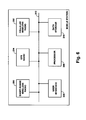
- FIG. 6 is a simplified block diagram depicting functional components of a mobile station operable in the method.
- FIG. 7 is a simplified block diagram depicting functional components of a RAN operable in the method.
- FIG. 1 is a line drawing depicting a scenario in which an end-user mobile station determines its own location based on locations of nearby end-user mobile stations.
- the figure depicts four end-user mobile stations 12 , 14 , 16 , 18 each carried by a respective user.
- These mobile stations may be cellular telephones, personal digital assistants, portable notebook computers, or other types of mobile communication devices.
- mobile station 12 is currently located inside a building 20 , whereas the other mobile stations are located outside of the building.
- mobile stations 14 , 16 , 18 each have a clear enough view of the sky to receive signals 22 , 24 , 26 from GPS satellites (an example 28 of which is illustrated) and to thereby determine or facilitate determine of their locations (“GPS locations”).
- GPS locations GPS locations
- mobile station 12 is unable to receive GPS signals as the building obstructs its view of the sky, and so mobile station 12 cannot determine its own GPS location.
- mobile station 12 may advantageously use the locations of nearby mobile stations 14 , 16 , 18 to determine its own location.
- mobile station 12 may broadcast a short-range wireless query generally seeking the locations of nearby mobile stations.
- mobile stations 14 , 16 , 18 may receive the short-range wireless query broadcast from mobile station 12 .
- they may then each send to mobile station 12 (or for that matter simply broadcast, for receipt by mobile station 12 ) a specification of their GPS location or a specification of their location as determined in some other manner, preferably as geographic coordinates such as latitude and longitude, and possibly altitude, coordinates.
- This back and forth communication between mobile station 12 and each nearby mobile station 14 , 16 , 18 is represented in FIG. 1 by arrows 30 , 32 , 34 and may occur through a short-range wireless communication protocol, such as ad hoc 802.11 signaling for instance, or any other mechanism now known or later developed.
- a short-range wireless communication protocol such as ad hoc 802.11 signaling for instance, or any other mechanism now known or later developed.
- mobile station 12 will preferably determine how far away each nearby mobile station is.
- each nearby mobile station may include in its response to mobile station a send-timestamp indicating when the nearby mobile station transmitted its location.
- Mobile station 12 may then read that send-timestamp upon receipt of the response and compare the send time to the current time so as to determine an end-to-end delay for wireless transmission from the nearby mobile station to itself. Based on that delay, the mobile station may then compute its distance from the nearby mobile station.
- mobile station 12 may determine the distance of each responding mobile station in some other way, such as by pinging each responding mobile station for delay information, and/or by considering signal strength, for instance.
- mobile station 12 may then compute (approximate) its own location, through use of a basic triangulation process or any other appropriate algorithm. For instance, mobile station 12 may compute for each nearby mobile station a circle or arc centered around the nearby mobile station and having a radius equal to the determined distance of that nearby mobile station, and mobile station 12 may then take the intersection of those circles or arcs as a representation of its own location. (If altitudes are provided, this analysis can take three dimensions into account).
- mobile station 12 could apply just as well in other scenarios. For instance, it is not necessary that mobile station 12 lack a plain view of the sky. It may be the case that mobile station 12 is simply not equipped with a GPS receiver or for some other reason seeks to determine its location based on locations of nearby mobile stations, regardless of its capabilities. Further, although just three nearby mobile stations 14 , 16 , 18 are shown, it is also possible that some other number of mobile stations could provide their location information. If mobile station 12 receives location information from fewer nearby mobile stations, the determination its location may be less accurate. Whereas, if mobile station 12 receives location information from a greater number of nearby mobile stations, the determination of its location may be more accurate.
- FIG. 2 is next a simplified block diagram depicting an arrangement of the four mobile stations of FIG. 1 , to help explain the location determination process.
- the figure depicts for each nearby mobile station a circle 36 , 38 , 40 centered about the location of the nearby mobile station and having a radius equal to the distance between the nearby mobile station.
- mobile station 12 may programmatically compute or represent these circles in memory, and mobile station 12 may programmatically find the point or area of intersection of the circles as a representation of where mobile station 12 is located. Program logic to find the intersection of a group of circles in a plane is known and is therefore not described here. (Likewise, in the event this occurs in three dimensions, program logic to find the intersection of a group of spheres is known and is therefore not described here.)
- RAN 42 that serves mobile stations 12 , 14 , 16 , 18 .
- the RAN may be operated by a wireless carrier to which each mobile station subscribes for service (or with which each mobile station can otherwise engage in useful wireless communication, even if pursuant an inter-carrier roaming agreement), for instance.
- RAN 42 may operate in a well known manner to provide one or more wireless coverage areas (e.g., cells and cell sectors) 44 in which the illustrated mobile stations can operate and, preferably, to provide the mobile stations with connectivity to one or more transport networks (not shown) such as the public switched telephone network (PSTN) and the Internet.
- PSTN public switched telephone network
- the RAN may take various forms.
- the RAN is shown including a cellular base transceiver station (BTS) 46 and a base station controller (BSC) 48 .
- BTS base transceiver station
- BSC base station controller
- Radio frequency (RF) communications from the RAN in a given coverage area are divided into various “forward link” channels on which the RAN can broadcast or unicast information to mobile stations in the coverage area.
- RF communications in the other direction are divided into various “reverse link” channels on which mobile stations can send information to the RAN.
- These channels can be used in the present method to provide the additional enhancement noted above, namely, to trigger transmission of a trust-signal from the RAN to the nearby mobile stations 14 , 16 , 18 .
- FIG. 3 is a message flow diagram depicting how this enhanced process can work in practice.
- the message flow of FIG. 3 assumes that mobile station 12 has encountered a trigger event of some sort that cause mobile station 12 to initiate this process.
- a user of mobile station 12 may engage a program link or browser link on mobile station 12 that ultimately causes mobile station 12 to determine its own location, and mobile station 12 may then detect that it does not have a GPS signal and therefore seek to determine its own location through the present process instead.
- the mobile station may have received a request from some other network entity, such as a location-based service provider or other mobile station, to determine location.
- Other examples of triggers are possible as well.
- mobile station 12 may begin the process by sending to RAN 42 a request for RAN 42 to emit a trust-signal.
- Mobile station 12 may provide this request to RAN 42 in any of a variety of ways.
- mobile station 12 may provide the request to RAN 42 in the form of an origination message via an access channel, in much the same way that the mobile station may originate a phone call if the mobile station is so equipped.
- the origination message in this instance, however, can be specially coded to indicate that it is a request for a trust-signal.
- the origination message can carry a service option code that the RAN is arranged to treat as an indication that the message is a request for a trust-signal, as opposed to a service option code that the RAN would interpret as a request to initiate a phone call.
- mobile station 12 may include in its trust-signal request an identifier of itself, such as mobile identification number, network access identifier, MAC address, or the like, sufficient for the RAN to determine what mobile station is placing the request and for the RAN to authenticate the requesting device as a condition to responding. Further, mobile station 12 may include in the request a unique key that can be used subsequently in the process to enable mobile station 12 to communicate with the nearby mobile stations 14 , 16 , 18 .
- the unique key can be a randomly generated binary sequence or other value, preferably one generated dynamically for this location determination process.
- the RAN may authenticate mobile station 12 through any known authentication process and may determine by reference to a subscription record for mobile station 12 whether mobile station 12 is entitled to have the RAN provide a trust-signal as requested. This may be a special service offered by the wireless carrier, for a fee charged to the owner of the mobile station.
- the RAN then provides the trust-signal as shown at step 52 .
- the RAN preferably provides the trust-signal for receipt by mobile stations that are likely to be nearby the requesting mobile station.
- the RAN may simply broadcast the trust-signal on an overhead channel for receipt by mobile stations that are operating in the same wireless coverage area (e.g., cell sector) as the requesting mobile station, and perhaps in adjacent cell sectors.
- the RAN may include the trust-signal within a system parameter message or other control channel message that mobile stations in the coverage area would normally receive and read.
- FIG. 3 shows step 52 as involving transmission of three signals, one to each of the nearby mobile stations 14 , 16 , 18 . If RAN 42 broadcasts or multicasts the trust-signal for receipt by those nearby mobile stations, merely one instance of the signal could be transmitted, and all three nearby mobile stations may receive that transmission. Thus, the figure indicates that the group of transmissions may cooperatively constitute the trust-signal provided by the RAN.
- the RAN may programmatically select which nearby mobile stations (e.g., of those in the same or adjacent coverage area as mobile station 12 ) should receive the trust-signal, and the RAN may unicast the trust-signal to just those nearby mobile stations.
- the RAN may monitor communications by mobile stations, to determine which mobile stations have been engaging in communication with a location server in the wireless carrier's network and which mobile stations have been using GPS functions to determine their GPS locations.
- the RAN may then target the trust-signal to those mobile stations specifically, particularly because those mobile stations are more likely to already have an indication of their current GPS locations and can therefore more readily respond to a query from mobile station 12 .
- the trust-signal that the RAN broadcasts preferably includes some sort of code that the recipient mobile stations are arranged to treat as an indication that the signal is a trust-signal.
- the code may be a specially defined binary sequence.
- the trust-signal may include the unique key that was provided by the requesting mobile station, so as to uniquely associate the trust-signal with the requesting mobile station's location determination process.
- the RAN may itself generate a unique key and provide it in the trust-signal and also provide it in a response signal to the requesting mobile station (or the requesting mobile station can simply receive it by itself also receiving the trust-signal).
- the signal can function to notify each nearby mobile station that the RAN backs the exchange of location information between the nearby mobile station and the querying mobile station 12 .
- the signal can function as a trigger to cause the nearby mobile stations to begin scanning the short-range wireless airwaves (e.g., WiFi or Bluetooth) for a location query signal from mobile station 12 ; this can be a great benefit, as it may help conserve the battery power of the nearby mobile stations, by avoiding the need for them to monitor the short-range wireless airwaves until necessary.
- the short-range wireless airwaves e.g., WiFi or Bluetooth
- the unique key provided by the trust-signal can be used to facilitate direct (e.g., short-range) wireless communication between the querying mobile station and each nearby mobile station (i.e., direct peer-to-peer communication between the mobile stations, without the communication passing through the RAN on its way from one mobile station to another).
- the key could be used as a mutual pairing code to facilitate BLUETOOTH communication between the mobile stations.
- the key could be used in some other manner to mutually secure (e.g., encrypt) communications between the mobile stations.
- Other benefits may inure as well.
- mobile station 12 begins broadcasting a query to seek locations of nearby mobile stations.
- the mobile station will broadcast this query via a short-range wireless protocol, such as Wi-Fi or BLUETOOTH for instance, in much the same way that it is known today for mobile devices to broadcast data such as SSIDs or pairing keys.
- the query broadcast by the mobile station 12 may specify its identifier and the unique key, with the unique key being couched as a pairing key or otherwise serving to associate requests and responses for the location determination process at issue, and mobile station 12 may then await receipt of pairing responses from other mobile stations.
- the query may include a defined code that each recipient mobile station is arranged to treat as an indication that the query seeks an indication of the recipient's location.
- FIG. 3 shows step 54 as involving transmission of three signals, one to each of the nearby mobile stations 14 , 16 , 18 .
- mobile station 12 may unicast such query signals to the nearby mobile stations.
- mobile station 12 will broadcast a single query signal, and each nearby mobile station that is suitably equipped and is currently scanning the short-range wireless airwaves in search of such a query signal will receive the query signal. Further, to help ensure that this happens, mobile station 12 may repeatedly broadcast the query signal.
- each nearby mobile station may condition reporting of its location to mobile station 12 on the nearby mobile station having received both (i) the location query from mobile station 12 and (ii) the trust-signal from RAN 42 .
- each nearby mobile station will determine that it has received both the location query from the mobile station 12 and the trust-signal from RAN 42 .
- the nearby mobile station may associate these two received signals with each other if they both contain or reference some common data, such as the unique key, an identifier of mobile station 12 , or the like, or may associate the two received signals together in some other manner.
- mobile station 12 may obtain locations of nearby mobile stations without the need for involvement of RAN 42 and/or without the need for a trust-signal.
- the nearby mobile station will send its location to mobile station 12 , as shown at step 58 .
- This step assumes, of course, that the nearby mobile station itself is aware of its own location, or determines its location in some manner perhaps in response to the location query.
- the nearby mobile station may determine its own location with use of GPS signaling in various other ways to the extent possible.
- the nearby mobile station may work with RAN 42 to facilitate an assisted-GPS location determination.
- the nearby mobile station may collect signal delay measurements from three serving cellular base stations in the vicinity and may report the base station identifiers and delay measurements via RAN 42 to a location server (not shown).
- the location server may then perform a database lookup to determine the fixed locations of the three base stations and may convert the delay measurements into distances respectively between the nearby mobile station and each base station.
- the location server may then apply triangulation as described above to approximate the nearby mobile station's location.
- the location server may perform a database lookup to determine GPS satellites that should be in the sky over the approximated location of the nearby mobile station, and the location server may then send a signal to the nearby mobile station directing the nearby mobile station to tune to transmissions from those GPS satellites.
- the nearby mobile station may then report to the location server information about the GPS satellite signals that it then receives, such as delay information, which the location server may in turn use as a basis to more accurately triangulate the location of the nearby mobile station.
- the location server may then report that determined location to the nearby mobile station. (In an alternative process, some of the steps just described as being carried out by the location server could be carried out instead by the nearby mobile station itself).
- Another way for the nearby mobile station to determine its location is for the nearby mobile station to carry out the present method, just as mobile station 12 does, based on locations of nearby mobile stations. This iterative process will be described below.
- the nearby mobile station determines or comes to know its own location
- the nearby mobile conveys its location to mobile station 12 in response to the query from mobile station 12 as shown in FIG. 3 .
- the manner in which each nearby mobile station conveys its location to mobile station 12 may vary depending on the short-range wireless protocol used. Details of certain short-range wireless protocols are known and therefore not described here. Further, others are bound to be developed in the future and can be used as well.
- each nearby mobile station will include in its response to mobile station 12 at least a specification of the nearby mobile station's location (likely approximated), such as geographic coordinates.
- the nearby mobile station may include a send timestamp as indicated above, to enable mobile station 12 to determine the transmission delay from the nearby mobile station and to thereby approximate the distance from the nearby mobile station, so as to facilitate triangulation.
- the nearby mobile station may include in its response a level of accuracy of the indicated location of the nearby mobile station.
- the indication of level of accuracy may be a simple value, such as weighting factor, that the querying mobile station is arranged to interpret as an indication of the accuracy level of the nearby mobile station's provided location. If the nearby mobile station has determined its location with assisted GPS, the accuracy may be relatively high, and so the level of accuracy indicated in the response may be a value that designates high accuracy. On the other hand, if the nearby mobile station has determined its location with mere base station triangulation, the accuracy may be relative low, and so the level of accuracy indicated in the response may be a value that designates low accuracy.
- the nearby mobile station has determined its location with mere base station triangulation, the accuracy may be relative low, and so the level of accuracy indicated in the response may be a value that designates low accuracy.
- Various other examples are possible as well.
- Mobile station 12 may use these indicated levels of accuracy in various ways.
- mobile station 12 may determine from the levels of accuracy how many nearby mobile station locations the mobile station should use as a basis to determine its own location. If the indicated levels of accuracy are relatively high, then mobile station may decide that locations of three nearby mobile stations would suffice. Whereas, if the levels of accuracy are relatively low, then the mobile station may decide that locations of a greater number of nearby mobile stations should be factored into its location determination process.
- mobile station 12 may then apply triangulation or another suitable process to determine its own location, at step 60 . This process is illustrated further back in FIG. 2 .
- mobile station 12 programmatically defines for each nearby mobile station a circle centered about the provided location of the nearby mobile station and having a radius equal to the distance of the nearby mobile station.
- mobile station 12 defines a circle 36 centered about the location of mobile station 14 and having a radius equal to the distance that mobile station 12 computed between it and mobile station 14 .
- mobile station defines a circle 38 centered about the location of mobile station 16 and having a radius equal to the distance that mobile station 12 computed between it and mobile station 16 .
- mobile station defines a circle 40 centered about the location of mobile station 14 and having a radius equal to the distance that mobile station 12 computed between it and mobile station 14 .
- Mobile station then programmatically finds the point or area of intersection of those circles, and mobile station assigns that point of intersection (or a representative point in the determined area of intersection) as a representation of the location of mobile station 12 .
- FIG. 4 This iterative process is generally illustrated in part by FIG. 4 , in a scenario where mobile station 18 applies the present method to determine its own location based on locations of nearby mobile stations 80 , 82 , 84 .
- mobile station 18 could determine its own location based on locations of mobile stations including, for instance, mobile stations 14 and 16 if possible; for clarity, however, mobile station 18 is shown using locations of other nearby mobile stations as a basis to determine its location.
- mobile station 18 may learn the locations and distance of nearby mobile stations 80 , 82 , 84 according to the present method. For instance, mobile station 18 may broadcast a location query via a short-range wireless protocol, and nearby mobile stations 80 , 82 , 84 may respond with indications of their locations. Further, mobile station 18 may request RAN 42 to provide a trust-signal, and nearby mobile stations 80 , 82 , 84 may condition reporting of their locations to mobile station 18 on receipt of both the query from mobile station 18 and the trust-signal from RAN 42 . Mobile station 18 may then also determine distances for each of the nearby mobile stations 80 , 82 , 84 .
- Mobile station may then define circles 86 , 88 , 90 respectively centered about each nearby mobile station and having radii equal to the determined distances. Mobile station 18 may then find the intersection of those circles and treat that intersection as a representation of its own location, which mobile station 18 may report to mobile station 12 in the process described above.
- mobile station 18 may receive indications of level of accuracy from the various nearby mobile stations 80 , 82 , 84 . Mobile station 18 may then use those levels of accuracy in the ways indicated above but may further use the levels of accuracy cooperatively to define a level of accuracy of the location of mobile station 18 that mobile station 18 determines through this process. For instance, if mobile station 18 receives only three relatively-low accuracy locations from nearby mobile stations 80 , 82 , 84 , then mobile station 18 may designate the determined location of mobile station 18 as a low-accuracy location. When mobile station 18 reports that location to mobile station 12 in the process above, mobile station 18 may then include in the report an indication that the location is low-accuracy, to help facilitate the process as described above.
- FIG. 5 a flow chart is provided to further illustrate some of the functions that can be carried out in accordance with an example of the present method, to determine the location of a given mobile station, such as mobile station 12 , based on the locations of nearby mobile stations, such as mobile stations 14 , 16 , 18 .
- mobile station 12 wirelessly signals to RAN 42 to cause RAN 42 to wirelessly output a trust-signal for receipt by the nearby mobile stations.
- this trust-signal may cause the nearby mobile stations to turn on their short-range radios so as to begin scanning for a location query.
- the mobile station wirelessly outputs a location query for receipt by the nearby mobile stations.
- each nearby mobile station receives both the trust-signal from the RAN and the location query from the given mobile station and, responsive to receiving both the trust-signal and the location query, wirelessly outputs an indication of its own location.
- mobile station 12 receives from each nearby mobile station the wirelessly output indication of the location of the nearby mobile station. Further, at step 108 , mobile station 12 determines, respectively for each nearby mobile station, a distance between the given mobile station and the nearby mobile station. At step 110 , mobile station then determines its own location based on the received indications of locations of the nearby mobile stations and the determined distances between the given mobile station and each nearby mobile station. Alternatively, rather than mobile station 12 itself making this final determination, mobile station 12 may send the received indications of locations and determined distances to another entity, such as a server via RAN 42 , and that entity may determine the location of mobile station 12 based on that data. In any event, the determined location may then be used to facilitate a location-based service, such as emergency response or a commercial service for instance, at step 112 .
- a location-based service such as emergency response or a commercial service for instance
- FIG. 6 is next a simplified block diagram showing functional components of a mobile station operable in accordance with an example of the present method.
- the mobile station may include a short-range wireless radio 200 , a cellular wireless radio 202 , a GPS radio 204 , a user interface 206 , a processor 208 , and data storage 210 , all of which may be communicatively linked together by a system bus, network, or other connection mechanism 212 .
- Short-range wireless radio 200 may comprise a transceiver suitable for allowing the mobile station to engage in wireless communication with other mobile stations according to a short-range wireless protocol, such as BLUETOOTH, Wi-Fi, or another such protocol now known or later developed.
- a short-range wireless protocol such as BLUETOOTH, Wi-Fi, or another such protocol now known or later developed.
- the short-range wireless radio 200 may comprise a suitable chipset and antenna, examples of which are well known.
- cellular wireless radio 202 may comprise a transceiver suitable for allowing the mobile station to engage in cellular wireless communication with RAN 42 according to a cellular wireless protocol such as one of those noted above for instance, or others later developed.
- cellular wireless radio 202 may similarly comprise a suitable chipset and antenna, examples of which are also well known.
- Cellular wireless radio 202 may be integrated together with short-range wireless radio 200 , such as on a common chipset and possibly sharing a common antenna arrangement.
- GPS radio 204 may comprise a GPS chipset and antenna suitable for allowing the mobile station to tune to various GPS satellites and to receive signals from the satellites, so as to facilitate GPS location determination as described above for instance.
- GPS radio 204 may also be integrated with short-range wireless radio 200 and/or with cellular wireless radio 202 , such as on a common chipset and sharing a common antenna arrangement for example.
- User interface 206 may comprise input and output components to facilitate user interaction with the WCD.
- user interface 206 may comprise a keypad, touch-sensitive screen, microphone, camera, and/or other input components, and a display screen, loudspeaker, and/or other output components.
- the mobile station might not include any user interface. This may be the case, for instance, if the mobile station comprises a data card (such as a PCMCIA card, an ES card, or a USB card) that couples with a device such as a notebook computer or the like.
- a data card such as a PCMCIA card, an ES card, or a USB card
- Processor 208 may comprise one or more general purposes processors (e.g., INTEL microprocessors) and/or one or more special-purpose processors (e.g., digital signal processors or application specific integrated circuits) and may be integrated with any of the wireless radios noted above.
- data storage 210 may comprise one or more volatile and/or non-volatile storage components, such as magnetic, optical, or organic storage components, and may be integrated with processor 208 .
- Data storage 210 preferably contains program instructions executable by processor 208 to carry out various mobile station functions described herein, although such functions can be implemented more generally by hardware, firmware, and/or software.
- the mobile station may function to detect a trigger for determining its own location and, perhaps after determining that it is unable to receive GPS signals, to initiate the present process of determining its location based on locations of nearby mobile stations.
- the mobile station may function to send a trust-signal request via cellular wireless radio 202 to RAN 42 to cause RAN 42 to emit a trust-signal, and the mobile station may function to broadcast a location query via short-range wireless radio 200 to seek location information from nearby mobile stations.
- the mobile station may function to determine its own location based upon locations and distances of nearby mobile stations.
- the mobile station may function to determine and report its own location. For instance, the mobile station may function to determine its own location as a GPS location if possible, or the mobile station may function to determine its own location through the present process, based on locations of other nearby mobile stations. Further, the mobile station may condition such reporting on its receipt of a location query and a trust-signal, and may include a send-timestamp in its report so as to enable the querying mobile station to determine distance and thus to determine location through triangulation or another algorithm.
- FIG. 7 is next a simplified block diagram showing functional components of a RAN operable in accordance with an example of the present method.
- the RAN includes a cellular wireless radio 300 , a processor 302 , and data storage 304 , which may be provided as features of one or more RAN elements such as BTS 46 or BSC 48 for instance, or may be provided in some entity or other manner.
- Cellular wireless radio 300 may comprise a transceiver suitable for communicating with and serving various mobile stations according to a cellular wireless protocol such as one of those noted above for instance, or others later developed.
- cellular wireless radio 300 may comprise a suitable chipset and antenna arrangement (e.g., on an antenna tower), examples of which are well known.
- Processor 302 may comprise a one or more general purposes processors and/or one or more special-purpose processors and may be integrated with cellular wireless radio 300 .
- data storage 304 may comprise one or more volatile and/or non-volatile storage components, such as magnetic, optical, or organic storage components, and may be integrated with processor 302 .
- Data storage 304 preferably contains program instructions executable by processor 302 to carry out various RAN functions described herein, although such functions can be implemented more generally by hardware, firmware, and/or software.
- the RAN may function to receive via cellular wireless radio 300 a trust-signal request from a mobile station, to authenticate the mobile station, and to responsively broadcast a trust-signal via cellular wireless radio 300 for receipt by mobile stations nearby the requesting mobile station (such as those in the same coverage area or an adjacent coverage area). Further, the RAN may provide the mobile stations with other service, such as connectivity with one or more transport networks and the ability to communicate with a location server or the like as discussed above.
Abstract
Description
Claims (20)
Priority Applications (1)
| Application Number | Priority Date | Filing Date | Title |
|---|---|---|---|
| US12/465,846 US8417264B1 (en) | 2009-05-14 | 2009-05-14 | Method and apparatus for determining location of a mobile station based on locations of multiple nearby mobile stations |
Applications Claiming Priority (1)
| Application Number | Priority Date | Filing Date | Title |
|---|---|---|---|
| US12/465,846 US8417264B1 (en) | 2009-05-14 | 2009-05-14 | Method and apparatus for determining location of a mobile station based on locations of multiple nearby mobile stations |
Publications (1)
| Publication Number | Publication Date |
|---|---|
| US8417264B1 true US8417264B1 (en) | 2013-04-09 |
Family
ID=47999310
Family Applications (1)
| Application Number | Title | Priority Date | Filing Date |
|---|---|---|---|
| US12/465,846 Active 2030-06-05 US8417264B1 (en) | 2009-05-14 | 2009-05-14 | Method and apparatus for determining location of a mobile station based on locations of multiple nearby mobile stations |
Country Status (1)
| Country | Link |
|---|---|
| US (1) | US8417264B1 (en) |
Cited By (45)
| Publication number | Priority date | Publication date | Assignee | Title |
|---|---|---|---|---|
| US20110251888A1 (en) * | 2010-04-09 | 2011-10-13 | Patrick Lee Faith | System and Method for Managing Tailored Marketing to Users of Wireless Devices |
| US20120083278A1 (en) * | 2010-10-01 | 2012-04-05 | Muhammad Ali Kazmi | Positioning measurements and carrier switching in multi-carrier wireless communication networks |
| US20120289243A1 (en) * | 2011-05-11 | 2012-11-15 | Cambridge Silicon Radio Limited | Cooperative positioning |
| US20130080598A1 (en) * | 2011-09-26 | 2013-03-28 | Alibaba Group Holding Limited | Determining the physical location of a client |
| US20130109407A1 (en) * | 2010-02-25 | 2013-05-02 | At&T Mobility Ii Llc | Sharing timed fingerprint location information |
| US20140120977A1 (en) * | 2012-10-25 | 2014-05-01 | David Amis | Methods and systems for providing multiple coordinated safety responses |
| US20140160951A1 (en) * | 2012-12-11 | 2014-06-12 | Yaron Alpert | Apparatus, system and method of simultaneous connectivity to location origin transceivers |
| US8886219B2 (en) | 2010-02-25 | 2014-11-11 | At&T Mobility Ii Llc | Timed fingerprint locating in wireless networks |
| US8892054B2 (en) | 2012-07-17 | 2014-11-18 | At&T Mobility Ii Llc | Facilitation of delay error correction in timing-based location systems |
| US8892112B2 (en) | 2011-07-21 | 2014-11-18 | At&T Mobility Ii Llc | Selection of a radio access bearer resource based on radio access bearer resource historical information |
| US8897802B2 (en) | 2011-07-21 | 2014-11-25 | At&T Mobility Ii Llc | Selection of a radio access technology resource based on radio access technology resource historical information |
| US8897805B2 (en) | 2012-06-15 | 2014-11-25 | At&T Intellectual Property I, L.P. | Geographic redundancy determination for time based location information in a wireless radio network |
| US8909247B2 (en) | 2011-11-08 | 2014-12-09 | At&T Mobility Ii Llc | Location based sharing of a network access credential |
| US8923134B2 (en) | 2011-08-29 | 2014-12-30 | At&T Mobility Ii Llc | Prioritizing network failure tickets using mobile location data |
| US8925104B2 (en) | 2012-04-13 | 2014-12-30 | At&T Mobility Ii Llc | Event driven permissive sharing of information |
| US8929827B2 (en) | 2012-06-04 | 2015-01-06 | At&T Mobility Ii Llc | Adaptive calibration of measurements for a wireless radio network |
| US8929914B2 (en) | 2009-01-23 | 2015-01-06 | At&T Mobility Ii Llc | Compensation of propagation delays of wireless signals |
| US20150011240A1 (en) * | 2012-02-20 | 2015-01-08 | Huawei Technologies Co., Ltd. | Network positioning method and related equipment |
| US8938258B2 (en) | 2012-06-14 | 2015-01-20 | At&T Mobility Ii Llc | Reference based location information for a wireless network |
| US8970432B2 (en) | 2011-11-28 | 2015-03-03 | At&T Mobility Ii Llc | Femtocell calibration for timing based locating systems |
| US8996031B2 (en) | 2010-08-27 | 2015-03-31 | At&T Mobility Ii Llc | Location estimation of a mobile device in a UMTS network |
| US20150095155A1 (en) * | 2013-09-30 | 2015-04-02 | Yahoo! Inc. | Method and system for collaborative location detection |
| US9009629B2 (en) | 2010-12-01 | 2015-04-14 | At&T Mobility Ii Llc | Motion-based user interface feature subsets |
| US9008698B2 (en) | 2011-07-21 | 2015-04-14 | At&T Mobility Ii Llc | Location analytics employing timed fingerprint location information |
| US9026133B2 (en) | 2011-11-28 | 2015-05-05 | At&T Mobility Ii Llc | Handset agent calibration for timing based locating systems |
| US9046592B2 (en) | 2012-06-13 | 2015-06-02 | At&T Mobility Ii Llc | Timed fingerprint locating at user equipment |
| US9053513B2 (en) | 2010-02-25 | 2015-06-09 | At&T Mobility Ii Llc | Fraud analysis for a location aware transaction |
| US9094929B2 (en) | 2012-06-12 | 2015-07-28 | At&T Mobility Ii Llc | Event tagging for mobile networks |
| US9103690B2 (en) | 2011-10-28 | 2015-08-11 | At&T Mobility Ii Llc | Automatic travel time and routing determinations in a wireless network |
| US9196157B2 (en) | 2010-02-25 | 2015-11-24 | AT&T Mobolity II LLC | Transportation analytics employing timed fingerprint location information |
| CN105445770A (en) * | 2014-08-28 | 2016-03-30 | 国际商业机器公司 | Positioning method of positioning device for satellite positioning system and positioning device |
| US9326263B2 (en) | 2012-06-13 | 2016-04-26 | At&T Mobility Ii Llc | Site location determination using crowd sourced propagation delay and location data |
| US9351111B1 (en) | 2015-03-06 | 2016-05-24 | At&T Mobility Ii Llc | Access to mobile location related information |
| US9351223B2 (en) | 2012-07-25 | 2016-05-24 | At&T Mobility Ii Llc | Assignment of hierarchical cell structures employing geolocation techniques |
| US9408174B2 (en) | 2012-06-19 | 2016-08-02 | At&T Mobility Ii Llc | Facilitation of timed fingerprint mobile device locating |
| US9426622B2 (en) * | 2014-12-22 | 2016-08-23 | Verizon Patent And Licensing Inc. | Determination of a location of a device based on information that identifies locations of other devices |
| US9462497B2 (en) | 2011-07-01 | 2016-10-04 | At&T Mobility Ii Llc | Subscriber data analysis and graphical rendering |
| US9519043B2 (en) | 2011-07-21 | 2016-12-13 | At&T Mobility Ii Llc | Estimating network based locating error in wireless networks |
| US20170064728A1 (en) * | 2010-11-12 | 2017-03-02 | Intellectual Ventures Holding 81 Llc | Scheduling communication in a wireless communication system |
| US9596571B1 (en) * | 2014-08-08 | 2017-03-14 | Polaris Wireless, Inc. | Estimating the location of a wireless terminal based on radio-frequency pattern matching and cooperative measurements |
| US20170171701A1 (en) * | 2014-06-12 | 2017-06-15 | Zte Corporation | Positioning method, device, positioning center, terminal and computer storage medium |
| US9769601B2 (en) | 2012-04-18 | 2017-09-19 | Google Inc. | Using peer devices to locate a mobile device |
| US10489737B2 (en) | 2015-12-21 | 2019-11-26 | Genetec Inc. | Method and system for viral identification of evacuees |
| US10516972B1 (en) | 2018-06-01 | 2019-12-24 | At&T Intellectual Property I, L.P. | Employing an alternate identifier for subscription access to mobile location information |
| US20210377908A1 (en) * | 2018-12-11 | 2021-12-02 | Qirfiraz Siddiqui | Apparatus, systems, and methods for determining a geo-location |
Citations (51)
| Publication number | Priority date | Publication date | Assignee | Title |
|---|---|---|---|---|
| US3710335A (en) | 1970-05-20 | 1973-01-09 | L Lepley | Azimuthal positioning system |
| US5528247A (en) | 1993-07-07 | 1996-06-18 | Mitsubishi Denki Kabushiki Kaisha | Mobile satellite communication system |
| US5736962A (en) | 1996-02-28 | 1998-04-07 | Tendler Cellular, Inc. | Time since last fix annunciation system for GPS-based wireless rescue system |
| US5974312A (en) | 1997-07-10 | 1999-10-26 | Ericsson Inc. | System and method for updating a memory in an electronic device via wireless data transfer |
| US5990826A (en) | 1997-10-07 | 1999-11-23 | Rockwell Science Center, Inc. | Interbuilding and urban canyon extension solution for global positioning systems |
| US6141542A (en) | 1997-07-31 | 2000-10-31 | Motorola, Inc. | Method and apparatus for controlling transmit diversity in a communication system |
| US6233448B1 (en) | 1998-07-22 | 2001-05-15 | Ericsson Inc. | System, method and apparatus for automatic feature activation/deactivation based upon positioning |
| US6246376B1 (en) | 2000-06-28 | 2001-06-12 | Texas Instruments Incorporated | Wireless location and direction indicator for multiple devices |
| US20010014597A1 (en) | 1997-10-28 | 2001-08-16 | Sony Corporation | Location messaging system using gps |
| US6295449B1 (en) | 1992-01-27 | 2001-09-25 | @Track Communications, Inc. | Data messaging in a communications network using a feature request |
| US20010048746A1 (en) | 2000-05-25 | 2001-12-06 | U. S. Philips Corporation | Method of estimating the location of a device |
| US20020118723A1 (en) * | 1999-08-02 | 2002-08-29 | Mccrady Dennis D. | Method and apparatus for determining the position of a mobile communication device using low accuracy clocks |
| US6456852B2 (en) | 1997-01-08 | 2002-09-24 | Trafficmaster Usa, Inc. | Internet distributed real-time wireless location database |
| US6473038B2 (en) | 2001-01-05 | 2002-10-29 | Motorola, Inc. | Method and apparatus for location estimation |
| US20020164995A1 (en) | 2001-05-03 | 2002-11-07 | International Business Machines Corporation | Method, system, and program for providing user location information for a personal information management system from transmitting devices |
| US20020177476A1 (en) | 2001-05-22 | 2002-11-28 | Chou Y. Hong | Durable global asset-tracking device and a method of using the same |
| US20030018744A1 (en) | 2001-02-07 | 2003-01-23 | Johanson James A. | Bluetooth device position display |
| US6560462B1 (en) | 2000-03-07 | 2003-05-06 | Samsung Electronics Co., Ltd. | System and method for determining the location of a mobile station in a wireless network |
| US6608592B2 (en) | 2002-01-18 | 2003-08-19 | Hewlett-Packard Development Company, Lp. | Location system using beacon transmitters |
| US6657549B1 (en) | 1999-08-05 | 2003-12-02 | Koninklijke Philips Electronics N.V. | Location finding system and method |
| US6748226B1 (en) | 1994-11-16 | 2004-06-08 | Minorplanet Systems Usa, Inc. | System and method for locating a mobile unit within the service area of a mobile communications network |
| US20040204097A1 (en) | 2002-10-25 | 2004-10-14 | Ibis Telecom, Inc. | Internet base station |
| US6898434B2 (en) | 2001-10-30 | 2005-05-24 | Hewlett-Packard Development Company, L.P. | Apparatus and method for the automatic positioning of information access points |
| US20050152396A1 (en) * | 2002-06-24 | 2005-07-14 | Roman Pichna | Ad hoc networking of terminals aided by a cellular network |
| US6963749B2 (en) | 2001-08-06 | 2005-11-08 | Denso Corporation | Radio communication terminal unit and method of transmitting location information |
| US6985812B2 (en) | 2001-04-13 | 2006-01-10 | General Dynamics Advanced Information Systems, Inc. | System and method for detecting interference in global positioning satellite signals |
| US6993345B2 (en) | 2001-08-30 | 2006-01-31 | Denso Corporation | Positioning system of wireless terminal |
| US20060072537A1 (en) | 2003-02-03 | 2006-04-06 | Don Lee | System for providing wireless internet mobile communication service and method of the same |
| US7027808B2 (en) | 2002-05-21 | 2006-04-11 | Philip Bernard Wesby | System and method for monitoring and control of wireless modules linked to assets |
| US20060087999A1 (en) * | 2004-10-22 | 2006-04-27 | Alcatel | Method of authenticating a mobile network node in establishing a peer-to-peer secure context between a pair of communicating mobile network nodes |
| US20060291427A1 (en) | 2005-06-25 | 2006-12-28 | Park Sun-Yong | Method for identifying home cell and apparatus thereof |
| US7181207B1 (en) | 1998-12-30 | 2007-02-20 | At&T Corp. | Method and apparatus for over-the-air activation of neighborhood cordless-type services |
| US7221928B2 (en) | 2003-10-01 | 2007-05-22 | Laird Mark D | Mobile emergency notification system |
| US7227710B2 (en) | 2003-09-30 | 2007-06-05 | Hitachi Global Storage Technologies Netherlands B.V. | Method for operating disk drive having improved timing marks |
| US20070135140A1 (en) | 2005-12-12 | 2007-06-14 | Nokia Corporation | System and method for mobile school trip guard |
| US7257426B1 (en) | 1999-05-26 | 2007-08-14 | Johnson Controls Technology Company | Wireless communications systems and method |
| US7272121B2 (en) | 2001-06-19 | 2007-09-18 | Telcordia Technologies, Inc. | Methods and apparatus for a modular wireless system |
| US7283091B1 (en) | 2005-08-08 | 2007-10-16 | Trimble Navigation Limited | Radio positioning system for providing position and time for assisting GPS signal acquisition in mobile unit |
| US7313401B2 (en) | 1997-05-09 | 2007-12-25 | Sony Corporation | Positioning system using packet radio to determine position and to obtain information relative to a position |
| US20080085727A1 (en) * | 2006-06-14 | 2008-04-10 | Kratz Tyler M | System and method for determining mobile device position information |
| US20080119160A1 (en) | 2006-11-22 | 2008-05-22 | Laurent Andriantsiferana | Enhanced location-based billing for gprs/umts networks |
| US20080132245A1 (en) * | 2006-11-30 | 2008-06-05 | Motorola, Inc. | Method and apparatus for surreptitiously triggering the collection of data from a lost wireless communications device equipped with audio and/or video collection means |
| US20080244148A1 (en) | 2007-04-02 | 2008-10-02 | Go2Call.Com, Inc. | VoIP Enabled Femtocell with a USB Transceiver Station |
| US20080299992A1 (en) | 2007-06-01 | 2008-12-04 | Qualcomm Incorporated | Methods and Apparatus for Determining FEMTO Base Station Location |
| US20080318626A1 (en) * | 2007-06-22 | 2008-12-25 | Broadcom Corporation | Multi-mode mobile communication device with motion sensor and methods for use therewith |
| US20090011779A1 (en) | 2005-04-08 | 2009-01-08 | Seeker Wirles Pty. Ltd. | Mobile Location |
| US7577443B1 (en) | 2007-12-20 | 2009-08-18 | Sprint Spectrum L.P. | Mobile-station and macro-network-aided location determination of a low-cost internet base station (LCIB) |
| US7595752B2 (en) | 2002-10-02 | 2009-09-29 | Global Locate, Inc. | Method and apparatus for enhanced autonomous GPS |
| US7603128B1 (en) | 2003-06-09 | 2009-10-13 | Sprint Spectrum L.P. | System and method for wireless distribution of location-based information in an enclosure |
| US7668765B2 (en) | 2000-07-07 | 2010-02-23 | Decarta Inc. | Method and apparatus for location-sensitive, subsidized cell phone billing |
| US7831216B1 (en) | 2007-11-27 | 2010-11-09 | Sprint Spectrum L.P. | Mobile-station-assisted low-cost-internet-base-station-(LCIB) location determination |
-
2009
- 2009-05-14 US US12/465,846 patent/US8417264B1/en active Active
Patent Citations (52)
| Publication number | Priority date | Publication date | Assignee | Title |
|---|---|---|---|---|
| US3710335A (en) | 1970-05-20 | 1973-01-09 | L Lepley | Azimuthal positioning system |
| US6295449B1 (en) | 1992-01-27 | 2001-09-25 | @Track Communications, Inc. | Data messaging in a communications network using a feature request |
| US5528247A (en) | 1993-07-07 | 1996-06-18 | Mitsubishi Denki Kabushiki Kaisha | Mobile satellite communication system |
| US6748226B1 (en) | 1994-11-16 | 2004-06-08 | Minorplanet Systems Usa, Inc. | System and method for locating a mobile unit within the service area of a mobile communications network |
| US5736962A (en) | 1996-02-28 | 1998-04-07 | Tendler Cellular, Inc. | Time since last fix annunciation system for GPS-based wireless rescue system |
| US6456852B2 (en) | 1997-01-08 | 2002-09-24 | Trafficmaster Usa, Inc. | Internet distributed real-time wireless location database |
| US7313401B2 (en) | 1997-05-09 | 2007-12-25 | Sony Corporation | Positioning system using packet radio to determine position and to obtain information relative to a position |
| US5974312A (en) | 1997-07-10 | 1999-10-26 | Ericsson Inc. | System and method for updating a memory in an electronic device via wireless data transfer |
| US6141542A (en) | 1997-07-31 | 2000-10-31 | Motorola, Inc. | Method and apparatus for controlling transmit diversity in a communication system |
| US5990826A (en) | 1997-10-07 | 1999-11-23 | Rockwell Science Center, Inc. | Interbuilding and urban canyon extension solution for global positioning systems |
| US20010014597A1 (en) | 1997-10-28 | 2001-08-16 | Sony Corporation | Location messaging system using gps |
| US6233448B1 (en) | 1998-07-22 | 2001-05-15 | Ericsson Inc. | System, method and apparatus for automatic feature activation/deactivation based upon positioning |
| US7181207B1 (en) | 1998-12-30 | 2007-02-20 | At&T Corp. | Method and apparatus for over-the-air activation of neighborhood cordless-type services |
| US7257426B1 (en) | 1999-05-26 | 2007-08-14 | Johnson Controls Technology Company | Wireless communications systems and method |
| US20020118723A1 (en) * | 1999-08-02 | 2002-08-29 | Mccrady Dennis D. | Method and apparatus for determining the position of a mobile communication device using low accuracy clocks |
| US6657549B1 (en) | 1999-08-05 | 2003-12-02 | Koninklijke Philips Electronics N.V. | Location finding system and method |
| US6560462B1 (en) | 2000-03-07 | 2003-05-06 | Samsung Electronics Co., Ltd. | System and method for determining the location of a mobile station in a wireless network |
| US20010048746A1 (en) | 2000-05-25 | 2001-12-06 | U. S. Philips Corporation | Method of estimating the location of a device |
| US6246376B1 (en) | 2000-06-28 | 2001-06-12 | Texas Instruments Incorporated | Wireless location and direction indicator for multiple devices |
| US7668765B2 (en) | 2000-07-07 | 2010-02-23 | Decarta Inc. | Method and apparatus for location-sensitive, subsidized cell phone billing |
| US6473038B2 (en) | 2001-01-05 | 2002-10-29 | Motorola, Inc. | Method and apparatus for location estimation |
| US20030018744A1 (en) | 2001-02-07 | 2003-01-23 | Johanson James A. | Bluetooth device position display |
| US6985812B2 (en) | 2001-04-13 | 2006-01-10 | General Dynamics Advanced Information Systems, Inc. | System and method for detecting interference in global positioning satellite signals |
| US20020164995A1 (en) | 2001-05-03 | 2002-11-07 | International Business Machines Corporation | Method, system, and program for providing user location information for a personal information management system from transmitting devices |
| US20020177476A1 (en) | 2001-05-22 | 2002-11-28 | Chou Y. Hong | Durable global asset-tracking device and a method of using the same |
| US7272121B2 (en) | 2001-06-19 | 2007-09-18 | Telcordia Technologies, Inc. | Methods and apparatus for a modular wireless system |
| US6963749B2 (en) | 2001-08-06 | 2005-11-08 | Denso Corporation | Radio communication terminal unit and method of transmitting location information |
| US6993345B2 (en) | 2001-08-30 | 2006-01-31 | Denso Corporation | Positioning system of wireless terminal |
| US6898434B2 (en) | 2001-10-30 | 2005-05-24 | Hewlett-Packard Development Company, L.P. | Apparatus and method for the automatic positioning of information access points |
| US6608592B2 (en) | 2002-01-18 | 2003-08-19 | Hewlett-Packard Development Company, Lp. | Location system using beacon transmitters |
| US7027808B2 (en) | 2002-05-21 | 2006-04-11 | Philip Bernard Wesby | System and method for monitoring and control of wireless modules linked to assets |
| US20050152396A1 (en) * | 2002-06-24 | 2005-07-14 | Roman Pichna | Ad hoc networking of terminals aided by a cellular network |
| US7595752B2 (en) | 2002-10-02 | 2009-09-29 | Global Locate, Inc. | Method and apparatus for enhanced autonomous GPS |
| US7117015B2 (en) | 2002-10-25 | 2006-10-03 | Intel Corporation, Inc | Internet base station |
| US20040204097A1 (en) | 2002-10-25 | 2004-10-14 | Ibis Telecom, Inc. | Internet base station |
| US20060072537A1 (en) | 2003-02-03 | 2006-04-06 | Don Lee | System for providing wireless internet mobile communication service and method of the same |
| US7603128B1 (en) | 2003-06-09 | 2009-10-13 | Sprint Spectrum L.P. | System and method for wireless distribution of location-based information in an enclosure |
| US7227710B2 (en) | 2003-09-30 | 2007-06-05 | Hitachi Global Storage Technologies Netherlands B.V. | Method for operating disk drive having improved timing marks |
| US7221928B2 (en) | 2003-10-01 | 2007-05-22 | Laird Mark D | Mobile emergency notification system |
| US20060087999A1 (en) * | 2004-10-22 | 2006-04-27 | Alcatel | Method of authenticating a mobile network node in establishing a peer-to-peer secure context between a pair of communicating mobile network nodes |
| US20090011779A1 (en) | 2005-04-08 | 2009-01-08 | Seeker Wirles Pty. Ltd. | Mobile Location |
| US20060291427A1 (en) | 2005-06-25 | 2006-12-28 | Park Sun-Yong | Method for identifying home cell and apparatus thereof |
| US7283091B1 (en) | 2005-08-08 | 2007-10-16 | Trimble Navigation Limited | Radio positioning system for providing position and time for assisting GPS signal acquisition in mobile unit |
| US20070135140A1 (en) | 2005-12-12 | 2007-06-14 | Nokia Corporation | System and method for mobile school trip guard |
| US20080085727A1 (en) * | 2006-06-14 | 2008-04-10 | Kratz Tyler M | System and method for determining mobile device position information |
| US20080119160A1 (en) | 2006-11-22 | 2008-05-22 | Laurent Andriantsiferana | Enhanced location-based billing for gprs/umts networks |
| US20080132245A1 (en) * | 2006-11-30 | 2008-06-05 | Motorola, Inc. | Method and apparatus for surreptitiously triggering the collection of data from a lost wireless communications device equipped with audio and/or video collection means |
| US20080244148A1 (en) | 2007-04-02 | 2008-10-02 | Go2Call.Com, Inc. | VoIP Enabled Femtocell with a USB Transceiver Station |
| US20080299992A1 (en) | 2007-06-01 | 2008-12-04 | Qualcomm Incorporated | Methods and Apparatus for Determining FEMTO Base Station Location |
| US20080318626A1 (en) * | 2007-06-22 | 2008-12-25 | Broadcom Corporation | Multi-mode mobile communication device with motion sensor and methods for use therewith |
| US7831216B1 (en) | 2007-11-27 | 2010-11-09 | Sprint Spectrum L.P. | Mobile-station-assisted low-cost-internet-base-station-(LCIB) location determination |
| US7577443B1 (en) | 2007-12-20 | 2009-08-18 | Sprint Spectrum L.P. | Mobile-station and macro-network-aided location determination of a low-cost internet base station (LCIB) |
Non-Patent Citations (20)
| Title |
|---|
| G. Djuknic and R. Richton, "Geolocation and Assisted-GPS," Lucent White Paper, 2000. |
| M. Amundson, "Dead Reckoning for consumer Electronics," 2006 Honeywell International. |
| Notice of allowance from U.S. Appl. No. 11/945,964, dated Jul. 7, 2010. |
| Notice of allowance from U.S. Appl. No. 11/960,987, dated May 14, 2009. |
| Office Action from U.S. Appl. No. 10/457,603, dated Aug. 1, 2007. |
| Office Action from U.S. Appl. No. 10/457,603, dated Feb. 17, 2009. |
| Office Action from U.S. Appl. No. 10/457,603, dated Jan. 29, 2007. |
| Office Action from U.S. Appl. No. 10/457,603, dated Mar. 18, 2008. |
| Office Action from U.S. Appl. No. 10/457,603, dated Mar. 23, 2006. |
| Office Action from U.S. Appl. No. 10/457,603, dated Sep. 30, 2008. |
| Office Action from U.S. Appl. No. 10/457,603, dated Sep. 8, 2006. |
| Office action from U.S. Appl. No. 11/945,964, dated Dec. 24, 2009. |
| Office action from U.S. Appl. No. 11/954,072, dated Apr. 2, 2010. |
| Office action from U.S. Appl. No. 11/954,072, dated Aug. 8, 2011. |
| Office action from U.S. Appl. No. 11/954,072, dated Feb. 25, 2011. |
| Office action from U.S. Appl. No. 11/954,072, dated Jun. 15, 2010. |
| Office action from U.S. Appl. No. 11/954,072, dated Oct. 14, 2009. |
| Office action from U.S. Appl. No. 11/960,987, dated Dec. 11, 2008. |
| U.S. Appl. No. 10/457,603, filed Jun. 9, 2003. |
| U.S. Appl. No. 11/954,072, filed Dec. 11, 2007. |
Cited By (104)
| Publication number | Priority date | Publication date | Assignee | Title |
|---|---|---|---|---|
| US8929914B2 (en) | 2009-01-23 | 2015-01-06 | At&T Mobility Ii Llc | Compensation of propagation delays of wireless signals |
| US9008684B2 (en) * | 2010-02-25 | 2015-04-14 | At&T Mobility Ii Llc | Sharing timed fingerprint location information |
| US20130109407A1 (en) * | 2010-02-25 | 2013-05-02 | At&T Mobility Ii Llc | Sharing timed fingerprint location information |
| US9053513B2 (en) | 2010-02-25 | 2015-06-09 | At&T Mobility Ii Llc | Fraud analysis for a location aware transaction |
| US8886219B2 (en) | 2010-02-25 | 2014-11-11 | At&T Mobility Ii Llc | Timed fingerprint locating in wireless networks |
| US9196157B2 (en) | 2010-02-25 | 2015-11-24 | AT&T Mobolity II LLC | Transportation analytics employing timed fingerprint location information |
| US20110251888A1 (en) * | 2010-04-09 | 2011-10-13 | Patrick Lee Faith | System and Method for Managing Tailored Marketing to Users of Wireless Devices |
| US8996031B2 (en) | 2010-08-27 | 2015-03-31 | At&T Mobility Ii Llc | Location estimation of a mobile device in a UMTS network |
| US20120083278A1 (en) * | 2010-10-01 | 2012-04-05 | Muhammad Ali Kazmi | Positioning measurements and carrier switching in multi-carrier wireless communication networks |
| US10034205B2 (en) * | 2010-10-01 | 2018-07-24 | Telefonaktiebolaget Lm Ericsson (Publ) | Positioning measurements and carrier switching in multi-carrier wireless communication networks |
| US11678359B2 (en) * | 2010-11-12 | 2023-06-13 | Intellectual Ventures Holding 81 Llc | Scheduling communication in a wireless communication system |
| US10721753B2 (en) | 2010-11-12 | 2020-07-21 | Intellectual Ventures Holding 81 Llc | Scheduling communication in a wireless communication system |
| US20220312434A1 (en) * | 2010-11-12 | 2022-09-29 | Intellectual Ventures Holding 81 Llc | Scheduling communication in a wireless communication system |
| US9788341B2 (en) * | 2010-11-12 | 2017-10-10 | Intellectual Ventures Holding 81 Llc | Scheduling communication in a wireless communication system |
| US11363616B2 (en) | 2010-11-12 | 2022-06-14 | Intellectual Ventures Holding 81 Llc | Scheduling communication in a wireless communication system |
| US10237884B2 (en) | 2010-11-12 | 2019-03-19 | Intellectual Ventures Holding 81 Llc | Scheduling communication in a wireless communication system |
| US20170064728A1 (en) * | 2010-11-12 | 2017-03-02 | Intellectual Ventures Holding 81 Llc | Scheduling communication in a wireless communication system |
| US9813900B2 (en) | 2010-12-01 | 2017-11-07 | At&T Mobility Ii Llc | Motion-based user interface feature subsets |
| US9009629B2 (en) | 2010-12-01 | 2015-04-14 | At&T Mobility Ii Llc | Motion-based user interface feature subsets |
| US9213081B2 (en) * | 2011-05-11 | 2015-12-15 | Qualcomm Technologies International, Ltd. | Cooperative positioning |
| US20120289243A1 (en) * | 2011-05-11 | 2012-11-15 | Cambridge Silicon Radio Limited | Cooperative positioning |
| US10972928B2 (en) | 2011-07-01 | 2021-04-06 | At&T Mobility Ii Llc | Subscriber data analysis and graphical rendering |
| US10091678B2 (en) | 2011-07-01 | 2018-10-02 | At&T Mobility Ii Llc | Subscriber data analysis and graphical rendering |
| US9462497B2 (en) | 2011-07-01 | 2016-10-04 | At&T Mobility Ii Llc | Subscriber data analysis and graphical rendering |
| US11483727B2 (en) | 2011-07-01 | 2022-10-25 | At&T Mobility Ii Llc | Subscriber data analysis and graphical rendering |
| US10701577B2 (en) | 2011-07-01 | 2020-06-30 | At&T Mobility Ii Llc | Subscriber data analysis and graphical rendering |
| US9232525B2 (en) | 2011-07-21 | 2016-01-05 | At&T Mobility Ii Llc | Selection of a radio access technology resource based on radio access technology resource historical information |
| US8892112B2 (en) | 2011-07-21 | 2014-11-18 | At&T Mobility Ii Llc | Selection of a radio access bearer resource based on radio access bearer resource historical information |
| US9008698B2 (en) | 2011-07-21 | 2015-04-14 | At&T Mobility Ii Llc | Location analytics employing timed fingerprint location information |
| US8897802B2 (en) | 2011-07-21 | 2014-11-25 | At&T Mobility Ii Llc | Selection of a radio access technology resource based on radio access technology resource historical information |
| US10085270B2 (en) | 2011-07-21 | 2018-09-25 | At&T Mobility Ii Llc | Selection of a radio access technology resource based on radio access technology resource historical information |
| US9510355B2 (en) | 2011-07-21 | 2016-11-29 | At&T Mobility Ii Llc | Selection of a radio access technology resource based on radio access technology resource historical information |
| US9519043B2 (en) | 2011-07-21 | 2016-12-13 | At&T Mobility Ii Llc | Estimating network based locating error in wireless networks |
| US10229411B2 (en) | 2011-08-05 | 2019-03-12 | At&T Mobility Ii Llc | Fraud analysis for a location aware transaction |
| US8923134B2 (en) | 2011-08-29 | 2014-12-30 | At&T Mobility Ii Llc | Prioritizing network failure tickets using mobile location data |
| US9069052B2 (en) * | 2011-09-26 | 2015-06-30 | Alibaba Group Holding Limited | Determining the physical location of a client |
| US20130080598A1 (en) * | 2011-09-26 | 2013-03-28 | Alibaba Group Holding Limited | Determining the physical location of a client |
| US10448195B2 (en) | 2011-10-20 | 2019-10-15 | At&T Mobility Ii Llc | Transportation analytics employing timed fingerprint location information |
| US9191821B2 (en) | 2011-10-28 | 2015-11-17 | At&T Mobility Ii Llc | Sharing timed fingerprint location information |
| US9103690B2 (en) | 2011-10-28 | 2015-08-11 | At&T Mobility Ii Llc | Automatic travel time and routing determinations in a wireless network |
| US10206113B2 (en) | 2011-10-28 | 2019-02-12 | At&T Mobility Ii Llc | Sharing timed fingerprint location information |
| US9681300B2 (en) | 2011-10-28 | 2017-06-13 | At&T Mobility Ii Llc | Sharing timed fingerprint location information |
| US11212320B2 (en) | 2011-11-08 | 2021-12-28 | At&T Mobility Ii Llc | Location based sharing of a network access credential |
| US10594739B2 (en) | 2011-11-08 | 2020-03-17 | At&T Intellectual Property I, L.P. | Location based sharing of a network access credential |
| US10362066B2 (en) | 2011-11-08 | 2019-07-23 | At&T Intellectual Property I, L.P. | Location based sharing of a network access credential |
| US9232399B2 (en) | 2011-11-08 | 2016-01-05 | At&T Intellectual Property I, L.P. | Location based sharing of a network access credential |
| US8909247B2 (en) | 2011-11-08 | 2014-12-09 | At&T Mobility Ii Llc | Location based sharing of a network access credential |
| US10084824B2 (en) | 2011-11-08 | 2018-09-25 | At&T Intellectual Property I, L.P. | Location based sharing of a network access credential |
| US9667660B2 (en) | 2011-11-08 | 2017-05-30 | At&T Intellectual Property I, L.P. | Location based sharing of a network access credential |
| US9810765B2 (en) | 2011-11-28 | 2017-11-07 | At&T Mobility Ii Llc | Femtocell calibration for timing based locating systems |
| US8970432B2 (en) | 2011-11-28 | 2015-03-03 | At&T Mobility Ii Llc | Femtocell calibration for timing based locating systems |
| US9743369B2 (en) | 2011-11-28 | 2017-08-22 | At&T Mobility Ii Llc | Handset agent calibration for timing based locating systems |
| US9026133B2 (en) | 2011-11-28 | 2015-05-05 | At&T Mobility Ii Llc | Handset agent calibration for timing based locating systems |
| US11178510B2 (en) | 2012-02-20 | 2021-11-16 | Huawei Technologies Co., Ltd. | Network positioning method and related equipment |
| US20150011240A1 (en) * | 2012-02-20 | 2015-01-08 | Huawei Technologies Co., Ltd. | Network positioning method and related equipment |
| US9888348B2 (en) * | 2012-02-20 | 2018-02-06 | Huawei Technologies Co., Ltd. | UE-assisted network positioning method and related equipment |
| US10667084B2 (en) | 2012-02-20 | 2020-05-26 | Huawei Technologies Co., Ltd. | Network positioning method and related equipment |
| US20180139578A1 (en) * | 2012-02-20 | 2018-05-17 | Huawei Technologies Co., Ltd. | Network positioning method and related equipment |
| US8925104B2 (en) | 2012-04-13 | 2014-12-30 | At&T Mobility Ii Llc | Event driven permissive sharing of information |
| US9563784B2 (en) | 2012-04-13 | 2017-02-07 | At&T Mobility Ii Llc | Event driven permissive sharing of information |
| US9864875B2 (en) | 2012-04-13 | 2018-01-09 | At&T Mobility Ii Llc | Event driven permissive sharing of information |
| US9769601B2 (en) | 2012-04-18 | 2017-09-19 | Google Inc. | Using peer devices to locate a mobile device |
| US8929827B2 (en) | 2012-06-04 | 2015-01-06 | At&T Mobility Ii Llc | Adaptive calibration of measurements for a wireless radio network |
| US9955451B2 (en) | 2012-06-12 | 2018-04-24 | At&T Mobility Ii Llc | Event tagging for mobile networks |
| US9094929B2 (en) | 2012-06-12 | 2015-07-28 | At&T Mobility Ii Llc | Event tagging for mobile networks |
| US10687302B2 (en) | 2012-06-12 | 2020-06-16 | At&T Mobility Ii Llc | Event tagging for mobile networks |
| US9596671B2 (en) | 2012-06-12 | 2017-03-14 | At&T Mobility Ii Llc | Event tagging for mobile networks |
| US9723446B2 (en) | 2012-06-13 | 2017-08-01 | At&T Mobility Ii Llc | Site location determination using crowd sourced propagation delay and location data |
| US9046592B2 (en) | 2012-06-13 | 2015-06-02 | At&T Mobility Ii Llc | Timed fingerprint locating at user equipment |
| US9521647B2 (en) | 2012-06-13 | 2016-12-13 | At&T Mobility Ii Llc | Site location determination using crowd sourced propagation delay and location data |
| US10477347B2 (en) | 2012-06-13 | 2019-11-12 | At&T Mobility Ii Llc | Site location determination using crowd sourced propagation delay and location data |
| US9326263B2 (en) | 2012-06-13 | 2016-04-26 | At&T Mobility Ii Llc | Site location determination using crowd sourced propagation delay and location data |
| US9769623B2 (en) | 2012-06-14 | 2017-09-19 | At&T Mobility Ii Llc | Reference based location information for a wireless network |
| US8938258B2 (en) | 2012-06-14 | 2015-01-20 | At&T Mobility Ii Llc | Reference based location information for a wireless network |
| US9473897B2 (en) | 2012-06-14 | 2016-10-18 | At&T Mobility Ii Llc | Reference based location information for a wireless network |
| US9398556B2 (en) | 2012-06-15 | 2016-07-19 | At&T Intellectual Property I, L.P. | Geographic redundancy determination for time based location information in a wireless radio network |
| US9769615B2 (en) | 2012-06-15 | 2017-09-19 | At&T Intellectual Property I, L.P. | Geographic redundancy determination for time based location information in a wireless radio network |
| US9615349B2 (en) | 2012-06-15 | 2017-04-04 | At&T Intellectual Property I, L.P. | Geographic redundancy determination for time based location information in a wireless radio network |
| US8897805B2 (en) | 2012-06-15 | 2014-11-25 | At&T Intellectual Property I, L.P. | Geographic redundancy determination for time based location information in a wireless radio network |
| US10225816B2 (en) | 2012-06-19 | 2019-03-05 | At&T Mobility Ii Llc | Facilitation of timed fingerprint mobile device locating |
| US9408174B2 (en) | 2012-06-19 | 2016-08-02 | At&T Mobility Ii Llc | Facilitation of timed fingerprint mobile device locating |
| US9591495B2 (en) | 2012-07-17 | 2017-03-07 | At&T Mobility Ii Llc | Facilitation of delay error correction in timing-based location systems |
| US9247441B2 (en) | 2012-07-17 | 2016-01-26 | At&T Mobility Ii Llc | Facilitation of delay error correction in timing-based location systems |
| US8892054B2 (en) | 2012-07-17 | 2014-11-18 | At&T Mobility Ii Llc | Facilitation of delay error correction in timing-based location systems |
| US10383128B2 (en) | 2012-07-25 | 2019-08-13 | At&T Mobility Ii Llc | Assignment of hierarchical cell structures employing geolocation techniques |
| US9351223B2 (en) | 2012-07-25 | 2016-05-24 | At&T Mobility Ii Llc | Assignment of hierarchical cell structures employing geolocation techniques |
| US10039111B2 (en) | 2012-07-25 | 2018-07-31 | At&T Mobility Ii Llc | Assignment of hierarchical cell structures employing geolocation techniques |
| US20140120977A1 (en) * | 2012-10-25 | 2014-05-01 | David Amis | Methods and systems for providing multiple coordinated safety responses |
| US9807815B2 (en) * | 2012-12-11 | 2017-10-31 | Intel Corporation | Apparatus, system and method of simultaneous connectivity to location origin transceivers |
| US20140160951A1 (en) * | 2012-12-11 | 2014-06-12 | Yaron Alpert | Apparatus, system and method of simultaneous connectivity to location origin transceivers |
| US20150095155A1 (en) * | 2013-09-30 | 2015-04-02 | Yahoo! Inc. | Method and system for collaborative location detection |
| US20170171701A1 (en) * | 2014-06-12 | 2017-06-15 | Zte Corporation | Positioning method, device, positioning center, terminal and computer storage medium |
| US10306398B2 (en) * | 2014-06-12 | 2019-05-28 | Zte Corporation | Method, system, positioning center for locating a terminal and non-transitory computer storage medium |
| US10527708B2 (en) * | 2014-08-08 | 2020-01-07 | Polaris Wireless, Inc. | Estimating the location of a wireless terminal based on cooperative measurements |
| US9596571B1 (en) * | 2014-08-08 | 2017-03-14 | Polaris Wireless, Inc. | Estimating the location of a wireless terminal based on radio-frequency pattern matching and cooperative measurements |
| US9989620B1 (en) | 2014-08-08 | 2018-06-05 | Polaris Wireless, Inc. | Estimating the location of a wireless terminal based on radio-frequency pattern matching and cooperative measurements |
| CN105445770A (en) * | 2014-08-28 | 2016-03-30 | 国际商业机器公司 | Positioning method of positioning device for satellite positioning system and positioning device |
| US9426622B2 (en) * | 2014-12-22 | 2016-08-23 | Verizon Patent And Licensing Inc. | Determination of a location of a device based on information that identifies locations of other devices |
| US9351111B1 (en) | 2015-03-06 | 2016-05-24 | At&T Mobility Ii Llc | Access to mobile location related information |
| US10206056B2 (en) | 2015-03-06 | 2019-02-12 | At&T Mobility Ii Llc | Access to mobile location related information |
| US11042826B2 (en) | 2015-12-21 | 2021-06-22 | Genetec Inc. | Method and system for viral identification of evacuees |
| US10489737B2 (en) | 2015-12-21 | 2019-11-26 | Genetec Inc. | Method and system for viral identification of evacuees |
| US10516972B1 (en) | 2018-06-01 | 2019-12-24 | At&T Intellectual Property I, L.P. | Employing an alternate identifier for subscription access to mobile location information |
| US20210377908A1 (en) * | 2018-12-11 | 2021-12-02 | Qirfiraz Siddiqui | Apparatus, systems, and methods for determining a geo-location |
Similar Documents
| Publication | Publication Date | Title |
|---|---|---|
| US8417264B1 (en) | Method and apparatus for determining location of a mobile station based on locations of multiple nearby mobile stations | |
| US10877161B2 (en) | Positioning method in mobile network, base station, and mobile terminal | |
| KR101607605B1 (en) | Peer-to-peer location service | |
| US8644793B2 (en) | Method of determining a location of a mobile device and method of managing a list for use in such a method | |
| KR101762993B1 (en) | System and method for providing network access to electronic devices | |
| US8897801B2 (en) | Transmission of location information by a transmitter as an aid to location services | |
| US9220082B2 (en) | Method of determining a location of a mobile device and method of managing a list for use in such a method | |
| CN100359961C (en) | Location technology support determinations in wireless communication networks and devices | |
| US20120149387A1 (en) | Detecting mobile device usage within wireless networks | |
| US9651674B2 (en) | Devices, systems and methods for providing location information over a cellular network | |
| KR100772583B1 (en) | Method and system for localization of mobile phone using wpan, and localization server and control method for the same | |
| CN101518119A (en) | Sensor networks based on wireless devices | |
| CN102379115A (en) | Method and apparatus for determining location information | |
| US20130143589A1 (en) | Mobile communication circuit reporting location information and methods thereof | |
| US20110059751A1 (en) | Method and location server for determining a postion of a target device | |
| EP3200520B1 (en) | Cooperative locating method and wireless terminal | |
| US20130143584A1 (en) | System and method for user control of location determination | |
| US8125943B2 (en) | Method for positioning user equipment accessing multiple mobile networks | |
| US9210680B2 (en) | Method and apparatus for selecting a real time location service provider | |
| US8855676B2 (en) | Method and apparatus for providing satellite assistance data | |
| US20030014189A1 (en) | System and method for mobile communications terminal positioning | |
| CN106488556B (en) | method and device for correcting offset of positioning signal | |
| KR101107811B1 (en) | Method and System for Searching Wireless LAN Information of Mobile Communication Terminal and Mobile Communication Terminal Having Function Therefore | |
| KR101140393B1 (en) | Method and System for Location Transmission Condition Setting of Mobile Communication Terminal | |
| WO2014176733A1 (en) | Positioning method, small base station, and macro base station |
Legal Events
| Date | Code | Title | Description |
|---|---|---|---|
| AS | Assignment |
Owner name: SPRINT SPECTRUM L.P., KANSAS Free format text: ASSIGNMENT OF ASSIGNORS INTEREST;ASSIGNORS:WHITNEY, JASON K.;DELKER, JASON R.;EVERSON, JOHN M.;AND OTHERS;SIGNING DATES FROM 20090512 TO 20090513;REEL/FRAME:022683/0945 |
|
| STCF | Information on status: patent grant |
Free format text: PATENTED CASE |
|
| CC | Certificate of correction | ||
| FPAY | Fee payment |
Year of fee payment: 4 |
|
| AS | Assignment |
Owner name: DEUTSCHE BANK TRUST COMPANY AMERICAS, NEW YORK Free format text: GRANT OF FIRST PRIORITY AND JUNIOR PRIORITY SECURITY INTEREST IN PATENT RIGHTS;ASSIGNOR:SPRINT SPECTRUM L.P.;REEL/FRAME:041937/0632 Effective date: 20170203 |
|
| AS | Assignment |
Owner name: DEUTSCHE BANK TRUST COMPANY AMERICAS, NEW YORK Free format text: SECURITY AGREEMENT;ASSIGNORS:T-MOBILE USA, INC.;ISBV LLC;T-MOBILE CENTRAL LLC;AND OTHERS;REEL/FRAME:053182/0001 Effective date: 20200401 |
|
| AS | Assignment |
Owner name: SPRINT SPECTRUM L.P., KANSAS Free format text: TERMINATION AND RELEASE OF FIRST PRIORITY AND JUNIOR PRIORITY SECURITY INTEREST IN PATENT RIGHTS;ASSIGNOR:DEUTSCHE BANK TRUST COMPANY AMERICAS;REEL/FRAME:052313/0299 Effective date: 20200401 |
|
| MAFP | Maintenance fee payment |
Free format text: PAYMENT OF MAINTENANCE FEE, 8TH YEAR, LARGE ENTITY (ORIGINAL EVENT CODE: M1552); ENTITY STATUS OF PATENT OWNER: LARGE ENTITY Year of fee payment: 8 |
|
| AS | Assignment |
Owner name: SPRINT SPECTRUM LLC, WASHINGTON Free format text: CHANGE OF NAME;ASSIGNOR:SPRINT SPECTRUM L.P.;REEL/FRAME:059044/0022 Effective date: 20210325 |
|
| AS | Assignment |
Owner name: SPRINT SPECTRUM LLC, KANSAS Free format text: RELEASE BY SECURED PARTY;ASSIGNOR:DEUTSCHE BANK TRUST COMPANY AMERICAS;REEL/FRAME:062595/0001 Effective date: 20220822 Owner name: SPRINT INTERNATIONAL INCORPORATED, KANSAS Free format text: RELEASE BY SECURED PARTY;ASSIGNOR:DEUTSCHE BANK TRUST COMPANY AMERICAS;REEL/FRAME:062595/0001 Effective date: 20220822 Owner name: SPRINT COMMUNICATIONS COMPANY L.P., KANSAS Free format text: RELEASE BY SECURED PARTY;ASSIGNOR:DEUTSCHE BANK TRUST COMPANY AMERICAS;REEL/FRAME:062595/0001 Effective date: 20220822 Owner name: SPRINTCOM LLC, KANSAS Free format text: RELEASE BY SECURED PARTY;ASSIGNOR:DEUTSCHE BANK TRUST COMPANY AMERICAS;REEL/FRAME:062595/0001 Effective date: 20220822 Owner name: CLEARWIRE IP HOLDINGS LLC, KANSAS Free format text: RELEASE BY SECURED PARTY;ASSIGNOR:DEUTSCHE BANK TRUST COMPANY AMERICAS;REEL/FRAME:062595/0001 Effective date: 20220822 Owner name: CLEARWIRE COMMUNICATIONS LLC, KANSAS Free format text: RELEASE BY SECURED PARTY;ASSIGNOR:DEUTSCHE BANK TRUST COMPANY AMERICAS;REEL/FRAME:062595/0001 Effective date: 20220822 Owner name: BOOST WORLDWIDE, LLC, KANSAS Free format text: RELEASE BY SECURED PARTY;ASSIGNOR:DEUTSCHE BANK TRUST COMPANY AMERICAS;REEL/FRAME:062595/0001 Effective date: 20220822 Owner name: ASSURANCE WIRELESS USA, L.P., KANSAS Free format text: RELEASE BY SECURED PARTY;ASSIGNOR:DEUTSCHE BANK TRUST COMPANY AMERICAS;REEL/FRAME:062595/0001 Effective date: 20220822 Owner name: T-MOBILE USA, INC., WASHINGTON Free format text: RELEASE BY SECURED PARTY;ASSIGNOR:DEUTSCHE BANK TRUST COMPANY AMERICAS;REEL/FRAME:062595/0001 Effective date: 20220822 Owner name: T-MOBILE CENTRAL LLC, WASHINGTON Free format text: RELEASE BY SECURED PARTY;ASSIGNOR:DEUTSCHE BANK TRUST COMPANY AMERICAS;REEL/FRAME:062595/0001 Effective date: 20220822 Owner name: PUSHSPRING, LLC, WASHINGTON Free format text: RELEASE BY SECURED PARTY;ASSIGNOR:DEUTSCHE BANK TRUST COMPANY AMERICAS;REEL/FRAME:062595/0001 Effective date: 20220822 Owner name: LAYER3 TV, LLC, WASHINGTON Free format text: RELEASE BY SECURED PARTY;ASSIGNOR:DEUTSCHE BANK TRUST COMPANY AMERICAS;REEL/FRAME:062595/0001 Effective date: 20220822 Owner name: IBSV LLC, WASHINGTON Free format text: RELEASE BY SECURED PARTY;ASSIGNOR:DEUTSCHE BANK TRUST COMPANY AMERICAS;REEL/FRAME:062595/0001 Effective date: 20220822 |