US8098752B2 - Apparatus and method for supporting a plurality of MIMO modes in a wireless communication system - Google Patents
Apparatus and method for supporting a plurality of MIMO modes in a wireless communication system Download PDFInfo
- Publication number
- US8098752B2 US8098752B2 US12/221,225 US22122508A US8098752B2 US 8098752 B2 US8098752 B2 US 8098752B2 US 22122508 A US22122508 A US 22122508A US 8098752 B2 US8098752 B2 US 8098752B2
- Authority
- US
- United States
- Prior art keywords
- mode
- mimo
- receiver
- information
- mimo mode
- Prior art date
- Legal status (The legal status is an assumption and is not a legal conclusion. Google has not performed a legal analysis and makes no representation as to the accuracy of the status listed.)
- Expired - Fee Related, expires
Links
- 238000000034 method Methods 0.000 title claims abstract description 18
- 238000004891 communication Methods 0.000 title claims abstract description 12
- 230000005540 biological transmission Effects 0.000 claims abstract description 13
- 238000013468 resource allocation Methods 0.000 claims description 9
- 230000009977 dual effect Effects 0.000 claims description 6
- 238000005259 measurement Methods 0.000 claims description 4
- 230000003044 adaptive effect Effects 0.000 claims 2
- 238000010586 diagram Methods 0.000 description 9
- 230000008901 benefit Effects 0.000 description 3
- 239000011159 matrix material Substances 0.000 description 3
- 238000012986 modification Methods 0.000 description 2
- 230000004048 modification Effects 0.000 description 2
- 230000015556 catabolic process Effects 0.000 description 1
- 238000012937 correction Methods 0.000 description 1
- 230000007423 decrease Effects 0.000 description 1
- 230000007812 deficiency Effects 0.000 description 1
- 238000006731 degradation reaction Methods 0.000 description 1
- 230000008054 signal transmission Effects 0.000 description 1
Images


Classifications
-
- H—ELECTRICITY
- H04—ELECTRIC COMMUNICATION TECHNIQUE
- H04B—TRANSMISSION
- H04B7/00—Radio transmission systems, i.e. using radiation field
- H04B7/02—Diversity systems; Multi-antenna system, i.e. transmission or reception using multiple antennas
- H04B7/04—Diversity systems; Multi-antenna system, i.e. transmission or reception using multiple antennas using two or more spaced independent antennas
- H04B7/06—Diversity systems; Multi-antenna system, i.e. transmission or reception using multiple antennas using two or more spaced independent antennas at the transmitting station
- H04B7/0686—Hybrid systems, i.e. switching and simultaneous transmission
- H04B7/0689—Hybrid systems, i.e. switching and simultaneous transmission using different transmission schemes, at least one of them being a diversity transmission scheme
-
- H—ELECTRICITY
- H04—ELECTRIC COMMUNICATION TECHNIQUE
- H04B—TRANSMISSION
- H04B7/00—Radio transmission systems, i.e. using radiation field
- H04B7/02—Diversity systems; Multi-antenna system, i.e. transmission or reception using multiple antennas
- H04B7/04—Diversity systems; Multi-antenna system, i.e. transmission or reception using multiple antennas using two or more spaced independent antennas
- H04B7/0413—MIMO systems
- H04B7/0417—Feedback systems
-
- H—ELECTRICITY
- H04—ELECTRIC COMMUNICATION TECHNIQUE
- H04B—TRANSMISSION
- H04B7/00—Radio transmission systems, i.e. using radiation field
- H04B7/02—Diversity systems; Multi-antenna system, i.e. transmission or reception using multiple antennas
- H04B7/04—Diversity systems; Multi-antenna system, i.e. transmission or reception using multiple antennas using two or more spaced independent antennas
- H04B7/0413—MIMO systems
- H04B7/0426—Power distribution
- H04B7/0434—Power distribution using multiple eigenmodes
-
- H—ELECTRICITY
- H04—ELECTRIC COMMUNICATION TECHNIQUE
- H04B—TRANSMISSION
- H04B7/00—Radio transmission systems, i.e. using radiation field
- H04B7/02—Diversity systems; Multi-antenna system, i.e. transmission or reception using multiple antennas
- H04B7/04—Diversity systems; Multi-antenna system, i.e. transmission or reception using multiple antennas using two or more spaced independent antennas
- H04B7/06—Diversity systems; Multi-antenna system, i.e. transmission or reception using multiple antennas using two or more spaced independent antennas at the transmitting station
- H04B7/0697—Diversity systems; Multi-antenna system, i.e. transmission or reception using multiple antennas using two or more spaced independent antennas at the transmitting station using spatial multiplexing
-
- H—ELECTRICITY
- H04—ELECTRIC COMMUNICATION TECHNIQUE
- H04L—TRANSMISSION OF DIGITAL INFORMATION, e.g. TELEGRAPHIC COMMUNICATION
- H04L1/00—Arrangements for detecting or preventing errors in the information received
- H04L1/0001—Systems modifying transmission characteristics according to link quality, e.g. power backoff
- H04L1/0015—Systems modifying transmission characteristics according to link quality, e.g. power backoff characterised by the adaptation strategy
-
- H—ELECTRICITY
- H04—ELECTRIC COMMUNICATION TECHNIQUE
- H04L—TRANSMISSION OF DIGITAL INFORMATION, e.g. TELEGRAPHIC COMMUNICATION
- H04L1/00—Arrangements for detecting or preventing errors in the information received
- H04L1/0001—Systems modifying transmission characteristics according to link quality, e.g. power backoff
- H04L1/0023—Systems modifying transmission characteristics according to link quality, e.g. power backoff characterised by the signalling
- H04L1/0025—Transmission of mode-switching indication
-
- H—ELECTRICITY
- H04—ELECTRIC COMMUNICATION TECHNIQUE
- H04L—TRANSMISSION OF DIGITAL INFORMATION, e.g. TELEGRAPHIC COMMUNICATION
- H04L1/00—Arrangements for detecting or preventing errors in the information received
- H04L1/02—Arrangements for detecting or preventing errors in the information received by diversity reception
- H04L1/06—Arrangements for detecting or preventing errors in the information received by diversity reception using space diversity
- H04L1/0618—Space-time coding
-
- H—ELECTRICITY
- H04—ELECTRIC COMMUNICATION TECHNIQUE
- H04L—TRANSMISSION OF DIGITAL INFORMATION, e.g. TELEGRAPHIC COMMUNICATION
- H04L25/00—Baseband systems
- H04L25/02—Details ; arrangements for supplying electrical power along data transmission lines
- H04L25/03—Shaping networks in transmitter or receiver, e.g. adaptive shaping networks
- H04L25/03006—Arrangements for removing intersymbol interference
- H04L2025/03777—Arrangements for removing intersymbol interference characterised by the signalling
- H04L2025/03802—Signalling on the reverse channel
-
- H—ELECTRICITY
- H04—ELECTRIC COMMUNICATION TECHNIQUE
- H04L—TRANSMISSION OF DIGITAL INFORMATION, e.g. TELEGRAPHIC COMMUNICATION
- H04L25/00—Baseband systems
- H04L25/02—Details ; arrangements for supplying electrical power along data transmission lines
- H04L25/03—Shaping networks in transmitter or receiver, e.g. adaptive shaping networks
- H04L25/03006—Arrangements for removing intersymbol interference
- H04L25/03343—Arrangements at the transmitter end
Definitions
- the present invention generally relates to a wireless communication system. More particularly, the present invention relates to an apparatus and method for supporting a plurality of multiple input multiple output (MIMO) modes in a wireless communication system.
- MIMO multiple input multiple output
- a system with multiple transmit and receive antennas has recently attracted interest to increase the reliability or throughput of signal transmission and reception in wireless communication systems.
- Such a system is called a MIMO system and there are a plurality of modes supporting the MIMO system (i.e., MIMO modes).
- MIMO modes are categorized into open-loop (OL) mode and closed-loop (CL) mode.
- OL open-loop
- CL closed-loop
- Channel information is not fed back in the OL mode whereas channel information is fed back in the CL mode.
- a MIMO system using the OL mode is called an OL-MIMO system and a MIMO system using the CL mode is called a CL-MIMO system.
- the OL-MIMO system adopts space time coding (STC) in order to increase diversity order or multiplexing order, and the CL-MIMO system uses a different transmission scheme depending on whether there is a single or multiple receivers. If channel information feedback is very accurate, dirty paper coding (DPC) mode is used, in which the transmitter transmits data with channel interference eliminated.
- STC space time coding
- DPC dirty paper coding
- a unified MIMO system supporting both the OL mode and the CL mode is proposed.
- a receiver notifies a transmitter (i.e., a base station (BS)) of its channel status, and the BS allocates resources to the receiver according to the channel status in the unified MIMO system.
- BS base station
- an aspect of exemplary embodiments of the present invention is to provide an apparatus and method for reducing the amount of feedback information in a unified MIMO system.
- Another aspect of exemplary embodiments of the present invention provides an apparatus and method for selecting an optimal MIMO mode from among a plurality of MIMO modes, taking into account the environment of a receiver in a unified MIMO system.
- a method for supporting a plurality of MIMO modes in a receiver in a wireless communication system in which one of the plurality of MIMO modes is selected according to at least one of a received signal strength, a speed of the receiver, a correlation between a transmitter and the receiver, the presence or absence of channel quality information, a preceding index, and antenna information, a rank, and the number of users.
- Feedback information is generated in a transmission format corresponding to the selected MIMO mode, and the feedback information is transmitted to the transmitter using feedback resources allocated according to the selected MIMO mode.
- an apparatus for supporting a plurality of MIMO modes in a wireless communication system in which a MIMO mode decider selects one of the plurality of MIMO modes according to at least one of a received signal strength, a speed of the receiver, a correlation between a transmitter and the receiver, the presence or absence of channel quality information, a preceding index, and antenna information, a rank, and the number of users.
- a feedback generator generates feedback information in a transmission format corresponding to the selected MIMO mode and transmits the feedback information to the transmitter using feedback resources allocated according to the selected MIMO mode.
- FIG. 1 is a block diagram of a unified MIMO system according to an exemplary embodiment of the present invention
- FIG. 2 is a block diagram of a transmitter in the unified MIMO system according to an exemplary embodiment of the present invention
- FIG. 3 is a block diagram of a receiver in the unified MIMO system according to an exemplary embodiment of the present invention.
- FIG. 4 is a flowchart illustrating an operation for performing a MIMO mode in the receiver in the unified MIMO system according to an exemplary embodiment of the present invention
- FIGS. 5A and 5B are a flowchart illustrating an operation for selecting a MIMO mode in the receiver in the unified MIMO system according to an exemplary embodiment of the present invention
- FIG. 6 illustrates a mode selection mechanism based on the signal-to-interference and noise ratio (SINR) and speed of the receiver in the unified MIMO system according to an exemplary embodiment of the present invention
- FIGS. 7A and 7B are a flowchart illustrating an operation for allocating a channel for each MIMO mode in the transmitter in the unified MIMO system according to an exemplary embodiment of the present invention
- FIG. 8 is a diagram illustrating available MIMO modes for the transmitter and the receiver in the unified MIMO system according to an exemplary embodiment of the present invention
- FIG. 9 illustrates an application of MIMO modes under a new mobile environment in the unified MIMO system according to an exemplary embodiment of the present invention
- FIG. 10 illustrates an application of MIMO modes under a new nomadic environment in the unified MIMO system according to an exemplary embodiment of the present invention.
- FIG. 11 illustrates the structure of CL MIMO feedback information in the unified MIMO system according to an exemplary embodiment of the present invention.
- FIGS. 1 through 11 discussed below, and the various embodiments used to describe the principles of the present disclosure in this patent document are by way of illustration only and should not be construed in any way to limit the scope of the disclosure. Those skilled in the art will understand that the principles of the present disclosure may be implemented in any suitably arranged wireless communication system.
- Exemplary embodiments of the present invention provide an apparatus and method for reducing the amount of feedback information to efficiently use resources in a unified MIMO system.
- the exemplary embodiments of the present invention also provide an apparatus and method for selecting an optimal MIMO mode from among a plurality of MIMO modes, taking into account the environment of a receiver in a unified MIMO system.
- FIG. 1 is a block diagram of a unified MIMO system according to an exemplary embodiment of the present invention.
- each of receivers 110 , 120 and 130 selects an optimal MIMO mode from among a plurality of MIMO modes according to its environment and transmits information about the selected MIMO modes to a transmitter 100 .
- Each receiver also measures downlink channel information and transmits to the transmitter 100 feedback information 140 that includes at least one of the measured downlink channel information, channel state information (CSI), channel quality information/indicator (CQI), a codebook index, channel rank information, a whole or stream-based reception SINR, and decoding information.
- the CSI and CQI are optionally included in the feedback information depending on an available feedback channel.
- the transmitter 100 schedules data transmission according to the MIMO mode information and the feedback information received from the receivers 110 , 120 and 130 , allocates the receivers 110 , 120 and 130 to streams or antennas according to the scheduling result, and transmits to the receivers 110 , 120 and 130 a downlink frame that includes a downlink MAP message that provides information about the scheduling and resource allocation information for the receivers 110 , 120 and 130 , and a downlink burst area with data for the receivers 110 , 120 and 130 , as indicated by reference numeral 150 .
- the receivers 110 , 120 and 130 decode the downlink frame, thus acquiring their data.
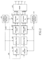
- FIG. 2 is a block diagram of the transmitter in the unified MIMO system according to an exemplary embodiment of the present invention.
- the transmitter includes feedback information receivers 202 and 214 , at least one transmission path 220 , and an adder 212 .
- a forward error correction (FEC) encoder 204 , a modulator 206 , a space-time encoder 208 , and a precoder 210 reside in the transmission path 220 .
- FEC forward error correction
- the feedback information receivers 202 and 214 receive feedback information and MIMO information from a receiver, determines a MIMO mode for the receiver based on the MIMO mode information, and transmits the determined MIMO mode to the transmission path 220 .
- the feedback information receiver 202 determines a modulation and coding scheme (MCS) level for the receiver according to the received feedback information and outputs information about the MCS level to the FEC encoder 204 , the modulator 206 , and the space-time encoder 208 . If the feedback information includes a precoder index being the index of a preceding matrix for use in the precoder 210 , the feedback information receiver 202 outputs the precoder index to the precoder 210 .
- MCS modulation and coding scheme
- information about uplink resources allocated to the receiver is generated according to the MIMO mode and a downlink frame including the uplink resource information is transmitted to the receiver.
- data is encoded, modulated, and space-time encoded according to the MCS level in the FEC encoder 204 , the modulator 206 , and the space-time encoder 208 and then precoded using the precoder index in the precoder 210 .
- the precoded signal is transmitted to the receiver.
- the FEC encoder 204 adds redundancy bits to information bits according to the MCS level so that the receiver can correct errors as well as detect the errors during decoding.
- the modulator 206 determines a modulation scheme according to the MCS level and modulates the coded bits received from the FEC encoder 204 .
- the space-time encoder 208 space-time encodes the modulation symbols received from the modulator 206 according to the MCS level.
- the precoder 210 decides on a precoder according to the precoder index and precodes the space-time coded modulation symbols using the determined precoder.
- the space-time coding and the preceding are optional according to the determined MIMO mode. For instance, if the MIMO mode is an OL MIMO mode, the feedback information receiver 202 determines an MCS level corresponding to the OL MIMO mode based on the feedback information.
- the space-time encoder 208 space-time encodes the modulation symbols according to the determined MCS level and outputs the space-time coded modulation symbols directly to the adder 212 without preceding in the precoder 210 because the OL MIMO mode uses space-time coding, not preceding.
- the feedback information receiver 202 determines an MCS level corresponding to the CL-DPC MIMO mode based on the feedback information.
- the space-time encoder 208 is deactivated, and the modulator 206 outputs the modulation symbols directly to the precoder 210 .
- the precoder 210 decides on a precoder according to the precoder index, precodes the modulation symbols using the determined precoder, and outputs the precoded symbols to the adder 212 . While it has been described that the transmitter supports the OL MIMO mode and the CL-DPC MIMO mode, it can support at least one of the OL MIMO mode, the CL MIMO mode, and the DPC mode.
- the transmitter can also schedule receivers operating in different MIMO modes simultaneously. While the transmitter is responsible for determining an MCS level in the above description, the receiver can determine an MCS level and notify the transmitter of the MCS level.
- FIG. 3 is a block diagram of a receiver in the unified MIMO system according to an exemplary embodiment of the present invention.
- the receiver includes a channel estimator 310 , a MIMO decoder 320 , a MIMO mode decider 370 , and a feedback generator 360 .
- the MIMO mode decider 370 has an SINR/speed measurer 330 , a MIMO mode selector 340 , and a MIMO mode generator 350 .
- the SINR/speed measurer 330 measures the SINR and speed of the receiver.
- the MIMO mode selector 340 selects the best MIMO mode from among a plurality of MIMO modes, taking into account the SINR and speed measurements.
- the MIMO mode generator 350 generates MIMO mode information indicating the selected MIMO mode.
- a feedback generator 360 transmits the MIMO mode information to the transmitter.
- a channel estimator 310 receives scheduling information and feedback resource allocation information about the receiver, and MIMO mode information indicating a MIMO mode determined by the transmitter. More specifically, the channel estimator 310 performs channel estimation by detecting common pilot symbols that are common to all users from a received signal, or by detecting dedicated pilot symbols specific to the receiver. After the channel estimation, the channel estimator 310 detects the scheduling information, the feedback resource allocation information, and the MIMO mode information from the received signal.
- the feedback generator 360 generates feedback information based on the scheduling information, the feedback resource allocation information, and the MIMO mode information received from the channel estimator 310 and transmits the feedback information in a transmission format corresponding to the MIMO mode information to the transmitter.
- the channel estimator 310 outputs the MIMO mode information to the MIMO decoder 320 .
- the MIMO decoder 320 selects a demodulation scheme corresponding to the MIMO mode information from among a plurality of demodulation schemes and demodulates the received signal according to the selected demodulation scheme.
- FIG. 4 is a flowchart illustrating an operation for performing a MIMO mode in the receiver in the unified MIMO system according to an exemplary embodiment of the present invention.
- the receiver measures its SINR and speed and selects a MIMO mode from among a plurality of MIMO modes according to the SINR or the speed in step 400 .
- the receiver generates feedback information based on scheduling information, MIMO mode information, and feedback resource allocation information received from the transmitter and transmits the feedback information to the transmitter.
- the receiver then receives a signal based on the MIMO mode information and acquires the received signal in step 420 .
- FIGS. 5A and 5B are a flowchart illustrating an operation for selecting a MIMO mode from among a plurality of MIMO modes in the receiver in the unified MIMO system according to an exemplary embodiment of the present invention.
- the receiver measures its SINR and speed in step 500 and determines its state by comparing the SINR or speed with a predetermined first criterion (Criterion 1) in step 510 .
- Criterion 1 is related to the speed or SINR of the receiver, preferably the speed of the receiver.
- the receiver selects an OL MIMO mode in step 520 and measures its rank in step 530 .
- the rank is the number of streams with eigenvectors equal to or higher than a predetermined value in a channel matrix with a size of the number of receive antennas x the number of transmit antennas.
- the receiver selects a space-time code from among a plurality of space-time codes, taking into account the rank information and the SINR measurement.
- the receiver determines whether a second criterion (Criterion 2) is satisfied in step 550 .
- Criterion 2 is the presence of a CQI, a precoding index, and antenna information (e.g., the number of transmit/receive antennas). If the receiver stores the CQI, the preceding index, and the antenna information, it proceeds to step 560 and otherwise, it jumps to step 580 .
- the receiver selects a CL MIMO mode.
- the receiver measures its rank and selects one of a single user (SU) mode, a dual user (DU) mode, and a multi-user (MU) mode according to the rank, the number of users, and an antenna spatial correlation in step 570 .
- SU single user
- DU dual user
- MU multi-user
- the receiver selects a DPC MIMO mode in step 580 and selects one of a block diagonalization (BD) mode, a regularized block diagonalization (RBD) mode, and a vector perturbation (VP) mode according to the SINR in step 590 .
- BD block diagonalization
- RBD regularized block diagonalization
- VP vector perturbation
- FIG. 6 illustrates a mode selection mechanism based on the SINR and speed of the receiver in the unified MIMO system according to an exemplary embodiment of the present invention.
- the horizontal axis represents the speed of the receiver and the vertical axis represents the SINR of the receiver.
- the receiver can select one of MIMO modes by comparing its SINR and speed with a plurality of thresholds.
- the receiver can measure the average SINR of streams. If the transmitter allocates a band-adaptive modulation and coding (Band-AMC) subchannel to the receiver, the receiver measures the SINR of each stream. Hence, the receiver can determine an MCS level on a stream-by-stream basis.
- the receiver selects one of MIMO modes by comparing its speed with speed thresholds and comparing its SINR with SINR thresholds. While the speed thresholds are set as 4 km/h, 10 km/h, 60 km/h and 120 km/h, they may vary depending on a wireless communication system. Also, while the speed and SINR of the receiver are taken into account for selection of a MIMO mode in the illustrated case of FIG. 6 , channel correlation information between the transmitter and the receiver can further be considered in addition to the speed and SINR of the receiver.
- FIGS. 7A and 7B are a flowchart illustrating an operation for allocating a channel to the receiver according to a MIMO mode suitable for the receiver in the transmitter in the unified MIMO system according to an exemplary embodiment of the present invention.
- the transmitter receives MIMO mode information from the receiver in step 700 and determines whether the received MIMO mode information indicates the OL MIMO mode in step 710 . If the received MIMO mode information indicates the OL MIMO mode, the transmitter allocates a diversity CQI channel to the receiver in order to receive information about an average MCS level for a total frequency band from the receiver in step 720 .
- the transmitter determines whether the MIMO mode information indicates the CL MIMO mode in step 730 . If the MIMO mode information indicates the CL MIMO mode, the transmitter determines whether the MIMO mode information further indicates the SU mode or the MU mode in step 740 . If the MIMO mode information further indicates the SU MIMO mode, the transmitter allocates a Band-AMC CQI channel to the receiver in order to receive information about a maximum band MCS level suitable for the SU mode from the receiver in step 750 .
- the transmitter allocates a Band-AMC CQI channel to the receiver in order to receive information about a maximum band MCS level suitable for the MU mode from the receiver in step 760 .
- Feedback information about the SU MIMO mode includes a rank and layer order index (RLOI), a maximum CQI of streams, and a delta CQI.
- Feedback information about the MU MIMO mode includes an RLOI, a maximum CQI of streams, and codebook information.
- step 770 the transmitter determines that the MIMO mode information indicates the DPC mode. Then the transmitter allocates a Band-AMC CQI channel to the receiver in order to receive information about a maximum band MCS level suitable for the DPC MIMO mode from the receiver in step 780 .
- FIG. 8 a MIMO mode diagram for the unified MIMO system will be described below.
- FIG. 8 is a diagram illustrating available MIMO modes for the transmitter and the receiver in the unified MIMO system according to an exemplary embodiment of the present invention.
- the MIMO modes are classified into the OL MIMO mode, the CL MIMO mode, and the DPC MIMO mode.
- the DPC MIMO mode requires the largest amount of feedback information and supports the highest data rate, whereas the OL MIMO mode requires the smallest amount of feedback information and supports the lowest data rate.
- the OL MIMO mode is distinguished from the CL MIMO mode by Criterion 1 and the CL MIMO mode is distinguished from the DPC MIMO mode by Criterion 2.
- Criterion 1 specifies a channel state value for the receiver.
- the channel state value is a speed threshold or a signal strength threshold (e.g., an SINR threshold).
- the OL MIMO mode is decided to be optimal for the receiver. If the speed of the receiver is smaller than the speed threshold, the CL MIMO mode is selected as optimal for the receiver.
- Criterion 2 is the presence of a CQI, a preceding index, and antenna information (e.g., the number of transmit/receive antennas). For example, if the receiver stores the CQI, the preceding index, and the antenna information, it is said that Criterion 2 is satisfied and the CL MIMO mode is determined as an optimal MIMO mode for the receiver. On the other hand, if the receiver does not store the CQI, the preceding index, and the antenna information, it is said that Criterion 2 is not satisfied, and the DPC MIMO mode is determined as an optimal MIMO mode for the receiver.
- the individual MIMO modes will be described in great detail.
- the OL MIMO mode does not require feedback information from the receiver.
- One of space-time codes is selected according to the rank and SINR of the receiver.
- the space-time codes include a diversity space-time code, a hybrid space-time code, and a spatial multiplexing space-time code.
- the diversity space-time code or the hybrid space-time code is selected according to a 3-1 criterion (T — 31), and the hybrid space-time code or the spatial multiplexing space-time code is selected according to a 3-2 criterion (T — 32).
- T — 31 and T — 32 are associated with rank and can be set to be different depending on a communication system.
- the receiver measures its rank, selects one of the diversity space-time code, the hybrid space-time code, and the spatial multiplexing space-time code according to the rank, generates feedback information including the selected space-time code, and transmits the feedback information to the transmitter.
- ranks and space-time code types is illustrated in Table 1 below.
- the diversity space-time code can be selected.
- the CL MIMO mode requires feedback information from the receiver.
- the CL MIMO mode is further branched into the SU MIMO mode, the DU MIMO mode, and the MU MIMO mode depending on the number of users for which antenna resources are divided and an antenna spatial correlation.
- T — 41 the DU mode in which two streams are allocated to each of two users
- T — 42 the MU mode in which one stream is allocated to each of four users.
- T — 41 and T — 42 are related to the number of users and an antenna spatial correlation.
- the DPC MIMO mode requires feedback information, especially very accurate channel information from the receiver.
- the DPC MIMO mode is further broken into a BD mode in which the inverse of a channel matrix is computed for a plurality of receivers each having a plurality of antennas, an RBD mode that further takes into account noise variance in the BD mode, and a VP mode that achieves a theoretically maximum channel capacity.
- the BD mode is distinguished from the RBD mode by a 5-1 criterion (T — 51), and the RBD mode is distinguished from the VP mode by a 5-2 criterion (T — 52).
- T — 51 and T-52 are related to SINR.
- FIG. 9 illustrates an application of MIMO modes under a new mobile environment in the unified MIMO system according to an exemplary embodiment of the present invention.
- the transmitter does not support the DPC MIMO mode for the receiver. Therefore, the transmitter provides a low data rate to the receiver in one of the OL MIMO mode and the CL MIMO mode in the new mobile environment.
- the transmitter when the receiver moves to a new nomadic environment characterized by a small cell size and a low user speed, the transmitter allocates resources to the receiver based on a feedback of channel state information from the receiver and supports a high data rate for the receiver. If the receiver has a high channel gain and can transmit perfect channel information to the transmitter, it requests allocation of a feedback link suitable for the DPC MIMO mode to the transmitter, and then the transmitter allocates resources to the receiver by sounding or an analog feedback.
- the resource allocation refers to allocation of time, frequency, and spatial resources.
- the transmitter can minimize the performance degradation of the receiver by use of a parameter that combines a space-time code of the OL MIMO mode with per user unitary rate control (PU2RC) of the CL MIMO mode. Also, the transmitter can further achieve a diversity gain using the space-time code.
- the PU2RC refers to extension of MU-MIMO to SU-MIMO.
- FIG. 10 illustrates an application of MIMO modes under a new nomadic environment in the unified MIMO system according to an exemplary embodiment of the present invention.
- the transmitter can operate in a unified MIMO system using the OL MIMO mode, the CL MIMO mode and the DPC MIMO mode.
- the receiver can requests the DPC MIMO mode to the transmitter.
- the transmitter can use a parameter being a combination of the BD mode and the VP mode. As a consequence, the receiver does not need to feed back information to the transmitter and simply has to perform modulo operation for DPC decoding.
- the good channel state of the receiver refers to a high channel gain of the receiver and transmission of perfect channel information to the transmitter.
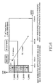
- FIG. 11 illustrates an exemplary structure of feedback information from the receiver in the CL MIMO mode in the unified MIMO system according to an exemplary embodiment of the present invention.
- the CL MIMO mode is further branched into the SU mode, the DU mode, and the MU mode.
- the feedback information includes a rank and layer order index (RLOI), a maximum CQI of streams, and a delta CQI.
- the feedback information includes the RLOI, the maximum CQI of streams, and a precoding index.
- the feedback information includes the RLOI, the maximum CQI of streams, and an offset channel quality information.
- Feedback information has the same length in the SU, DU and MU modes by adjusting the length of an RLOI in the SU and DU modes and the length of a precoding index in the MU mode.
- the RLOI can be two bits long, and the other bits can be filled with a preceding index for a plurality of users in the feedback information of the MU mode.
- a precoding index for determining a CQI order and a rank order is shortened in length, and an RLOI occupies four bits in the feedback information.
- the present invention advantageously minimizes the amount of feedback information since a receiver selects an optimal MIMO mode from among a plurality of MIMO modes according to its environment. Also, a transmitter can transmit a minimum amount of information required for resource allocation to the receiver.
Abstract
Description
| TABLE 1 | |||
| Rank (threshold) | Space-time code types | ||
| Below T_31 | Diversity | ||
| T_31 or higher and below T_32 | Hybrid | ||
| T_32 or higher | Spatial multiplexing | ||
Claims (16)
Applications Claiming Priority (3)
| Application Number | Priority Date | Filing Date | Title |
|---|---|---|---|
| KR10-2007-0077205 | 2007-07-31 | ||
| KR2007-0077205 | 2007-07-31 | ||
| KR20070077205 | 2007-07-31 |
Publications (2)
| Publication Number | Publication Date |
|---|---|
| US20090034639A1 US20090034639A1 (en) | 2009-02-05 |
| US8098752B2 true US8098752B2 (en) | 2012-01-17 |
Family
ID=40338107
Family Applications (1)
| Application Number | Title | Priority Date | Filing Date |
|---|---|---|---|
| US12/221,225 Expired - Fee Related US8098752B2 (en) | 2007-07-31 | 2008-07-31 | Apparatus and method for supporting a plurality of MIMO modes in a wireless communication system |
Country Status (2)
| Country | Link |
|---|---|
| US (1) | US8098752B2 (en) |
| KR (1) | KR20090013140A (en) |
Cited By (16)
| Publication number | Priority date | Publication date | Assignee | Title |
|---|---|---|---|---|
| US20120201321A1 (en) * | 2009-10-30 | 2012-08-09 | Nokia Corporation | Channel feedback to support efficient rank override |
| US20130094439A1 (en) * | 2011-10-17 | 2013-04-18 | Mehran Moshfeghi | Method and system for centralized distributed transceiver management |
| US20140133317A1 (en) * | 2012-11-09 | 2014-05-15 | Telefonaktiebolaget L M Ericsson (Publ) | Adaptive transmission mode switching |
| US20140133848A1 (en) * | 2012-11-15 | 2014-05-15 | Mitsubishi Electric Research Laboratories, Inc. | Adaptively Coding and Modulating Signals Transmitted Via Nonlinear Channels |
| US20140294115A1 (en) * | 2012-04-11 | 2014-10-02 | Huawei Technologies Co., Ltd. | Method and apparatus for configuring transmission mode |
| US20140314168A1 (en) * | 2011-11-30 | 2014-10-23 | Huawei Technologies Co., Ltd. | Data Transmission Method, Apparatus, and System |
| US9173187B2 (en) | 2008-03-31 | 2015-10-27 | Golba Llc | Determining the position of a mobile device using the characteristics of received signals and a reference database |
| US9197982B2 (en) | 2012-08-08 | 2015-11-24 | Golba Llc | Method and system for distributed transceivers for distributed access points connectivity |
| US9210683B2 (en) | 2009-07-09 | 2015-12-08 | Golba Llc | Method and system for device positioning utilizing distributed transceivers with array processing |
| US9366745B2 (en) | 2008-03-31 | 2016-06-14 | Golba Llc | Methods and systems for determining the location of an electronic device using multi-tone frequency signals |
| US9794814B2 (en) | 2012-11-28 | 2017-10-17 | Samsung Electronics Co., Ltd. | Method and apparatus for performing communication in a wireless communication system |
| CN107346982A (en) * | 2016-05-06 | 2017-11-14 | 北京信威通信技术股份有限公司 | A kind of descending multi-antenna transmission method and device |
| US9829560B2 (en) | 2008-03-31 | 2017-11-28 | Golba Llc | Determining the position of a mobile device using the characteristics of received signals and a reference database |
| US11018752B2 (en) | 2017-07-11 | 2021-05-25 | Silicon Valley Bank | Reconfigurable and modular active repeater device |
| US11183885B2 (en) * | 2016-05-13 | 2021-11-23 | Samsung Electronics Co., Ltd. | Wireless power transmission device and control method thereof |
| US11218892B2 (en) | 2012-11-28 | 2022-01-04 | Samsung Electronics Co., Ltd. | Method and apparatus for performing communication in a wireless communication system |
Families Citing this family (45)
| Publication number | Priority date | Publication date | Assignee | Title |
|---|---|---|---|---|
| KR101537591B1 (en) * | 2008-04-07 | 2015-07-20 | 엘지전자 주식회사 | Method for mode adaptation in MIMO system |
| KR101001015B1 (en) * | 2008-09-25 | 2010-12-14 | 한국전자통신연구원 | Multiple antenna wireless communication system for determining adaptably downlink transmission mode |
| WO2010060467A1 (en) * | 2008-11-26 | 2010-06-03 | Nokia Siemens Networks Oy | Transmission mode selection based on radio link quality and radio load on the air interface |
| US9094167B2 (en) * | 2009-02-02 | 2015-07-28 | Samsung Electronics Co., Ltd. | System and method for multi-user and multi-cell MIMO transmissions |
| US8284693B2 (en) * | 2009-02-03 | 2012-10-09 | Broadcom Corporation | Multi-stream priority-based space-time coding |
| US8274951B2 (en) * | 2009-03-17 | 2012-09-25 | Samsung Electronics Co., Ltd. | System and method for dynamic cell selection and resource mapping for CoMP joint transmission |
| EP3512219B1 (en) * | 2009-04-06 | 2022-05-04 | Marvell Asia Pte, Ltd. | Improved feedback strategies for multi-user mimo communication systems |
| KR101103136B1 (en) | 2009-04-08 | 2012-01-04 | 주식회사 세아네트웍스 | Apparatus and Method for Changing MIMO Mode in Wireless Communication System |
| CN101873159B (en) * | 2009-04-21 | 2013-01-16 | 华为技术有限公司 | Multi-input multi-output downlink transmission control method and device |
| KR101591403B1 (en) | 2009-04-30 | 2016-02-03 | 인텔렉추얼디스커버리 주식회사 | Method and Apparatus for Determining Precoding Matrix |
| US20100278278A1 (en) * | 2009-04-30 | 2010-11-04 | Lg Electronics Inc. | Method for setting precoder in open loop mimo system |
| US8396157B2 (en) * | 2009-05-14 | 2013-03-12 | Futurewei Technologies, Inc. | Probability based MIMO mode selection and switching system and method for wireless systems |
| CN101902305B (en) * | 2009-05-25 | 2013-10-30 | 富士通株式会社 | Communication device, communication method and base station |
| FR2947401B1 (en) * | 2009-06-26 | 2012-07-13 | Thales Sa | MULTI-ANTENNA COMMUNICATION SYSTEM |
| CN101944941B (en) * | 2009-07-03 | 2014-07-02 | 联想(上海)有限公司 | Method for controlling reconfigurable multiaerial system and mobile terminal |
| ES2358406B1 (en) * | 2009-07-07 | 2012-03-22 | Vodafone España, S.A.U. | RADIO NETWORK CONTROLLER AND METHOD TO SELECT A TRANSMISSION TECHNOLOGY FOR AN HSDPA CONNECTION. |
| CN101997586A (en) * | 2009-08-17 | 2011-03-30 | 中兴通讯股份有限公司 | Multi-carrier multi-antenna-based information feedback method and device |
| JP5380606B2 (en) * | 2009-10-30 | 2014-01-08 | エレクトロニクス アンド テレコミュニケーションズ リサーチ インスチチュート | Control and training symbol transmission method in multi-user wireless communication system |
| US8725084B2 (en) * | 2009-11-23 | 2014-05-13 | Cisco Technology, Inc. | MIMO mode switch management for beamformed MIMO systems |
| US8526519B2 (en) * | 2009-12-14 | 2013-09-03 | Texas Instruments Incorporated | Multi-rank precoding matrix indicator (PMI) feedback in a multiple-input multiple-output (MIMO) system |
| US8112049B2 (en) * | 2009-12-17 | 2012-02-07 | Telefonaktiebolaget Lm Ericsson (Publ) | Channel quality handling for precoder override |
| CN102122976A (en) | 2010-01-08 | 2011-07-13 | 上海贝尔股份有限公司 | Antenna selecting method and device for base station |
| US8750270B2 (en) * | 2010-02-25 | 2014-06-10 | Lg Electronics Inc. | Method and apparatus for transmitting feedback request and method and apparatus for receiving feedback request in wireless communication system |
| KR20110109992A (en) | 2010-03-29 | 2011-10-06 | 엘지전자 주식회사 | A method and apparatus for efficient feedback in a wireless communication system supporting multiple-antenna |
| EP2385440A1 (en) | 2010-05-07 | 2011-11-09 | ST-Ericsson SA | Method and system for controlling the operation of an electronic device |
| CN101860385B (en) * | 2010-06-23 | 2012-09-05 | 西安交通大学 | Channel modeling method for multi-input multi-output wireless communication system |
| US8547955B2 (en) * | 2010-07-28 | 2013-10-01 | Intel Corporation | Feedback scheme for MU-MIMO |
| US20120069927A1 (en) * | 2010-09-17 | 2012-03-22 | Intel Corporation | CQI feedback mechanisms for distortion-aware link adaptation toward enhanced multimedia communications |
| WO2012100691A1 (en) * | 2011-01-30 | 2012-08-02 | 北京新岸线无线技术有限公司 | Method and device for realizing multi-input multi-output |
| KR20120092278A (en) * | 2011-02-11 | 2012-08-21 | 삼성전자주식회사 | Method and apparatus for mimo precoding for distributed antenna systems based wireless communication |
| US8526380B1 (en) * | 2011-03-17 | 2013-09-03 | Sprint Communications Company L.P. | Dynamic transmission mode selection based on wireless communication device data rate capabilities |
| CN103354478A (en) | 2011-03-31 | 2013-10-16 | 北京新岸线移动多媒体技术有限公司 | Method used for realizing link self adaption, network device and terminal device |
| CN102832980B (en) * | 2011-06-14 | 2017-10-20 | 中兴通讯股份有限公司 | A kind of Uplink MIMO pattern method for switching between, device and equipment |
| US20130021925A1 (en) * | 2011-07-22 | 2013-01-24 | Sharp Laboratories Of America, Inc. | Coordinated multipoint (comp) transmission method selection and feedback requirements |
| JP5708345B2 (en) * | 2011-07-26 | 2015-04-30 | 富士通株式会社 | Wireless device and communication control method |
| EP2807756B1 (en) * | 2012-01-23 | 2021-05-26 | Telefonaktiebolaget LM Ericsson (publ) | Method and device for selecting precoding matrices based on representations of speed of related devices |
| CN104486041B (en) * | 2012-04-11 | 2018-06-05 | 华为技术有限公司 | A kind of transmission mode collocation method and device |
| CN102647217B (en) * | 2012-04-17 | 2015-01-14 | 上海交通大学 | Double-bounce half-duplex MIMO (Multiple-input multiple-output) relay network distributed type beam forming method |
| US9252905B2 (en) | 2012-09-24 | 2016-02-02 | Telefonaktiebolaget L M Ericsson (Publ) | Antenna resource management for multi-antenna structure |
| CN104079367B (en) * | 2013-03-25 | 2017-09-12 | 中国移动通信集团公司 | transmission mode switching method and device |
| JP2016149584A (en) * | 2013-06-10 | 2016-08-18 | シャープ株式会社 | Base station device, terminal, wireless communication system, integrated circuit |
| WO2017131268A1 (en) * | 2016-01-29 | 2017-08-03 | 한국과학기술원 | Apparatus and method for scheduling antenna system |
| EP3273624A1 (en) * | 2016-07-18 | 2018-01-24 | Institut Mines Telecom | Joint space-time and fec coding in multi-mode fiber optical transmission systems |
| KR20210012080A (en) * | 2019-07-23 | 2021-02-03 | 삼성전자주식회사 | Method for generating precoder and precoder generating device in multi user multiple input and multiple output communication system |
| US11522581B2 (en) * | 2020-05-08 | 2022-12-06 | Qualcomm Incorporated | Switching between intra-band multiple input multiple output and inter-band carrier aggregation |
Citations (12)
| Publication number | Priority date | Publication date | Assignee | Title |
|---|---|---|---|---|
| US20030185241A1 (en) * | 2002-04-01 | 2003-10-02 | Texas Instruments Incorporated | Wireless network scheduling data frames including physical layer configuration |
| US20040082311A1 (en) | 2002-10-28 | 2004-04-29 | Shiu Da-Shan | Utilizing speed and position information to select an operational mode in a wireless communication system |
| JP2006071325A (en) | 2004-08-31 | 2006-03-16 | Topukon Yamagata:Kk | Lens meter |
| JP2006100073A (en) | 2004-09-29 | 2006-04-13 | Hitachi Cable Ltd | Coaxial cable, and its manufacturing method, as well as connecting cable using that coaxial cable |
| KR20060033957A (en) | 2004-10-18 | 2006-04-21 | 엘지전자 주식회사 | Method of feedback of mimo mode and permutation type in ofdm/ofdma mobile communications system |
| JP2006110898A (en) | 2004-10-15 | 2006-04-27 | Toyo Tire & Rubber Co Ltd | Stock solution charging equipment for centrifugal casting machine |
| US7120199B2 (en) * | 2001-05-04 | 2006-10-10 | Telefonaktiebolaget Lm Ericsson (Publ) | Link adaptation for MIMO transmission schemes |
| US20070147536A1 (en) * | 2005-12-27 | 2007-06-28 | Ezer Melzer | Wireless communication device employing interference-sensitive mode selection and associated methods |
| US20070171849A1 (en) * | 2006-01-03 | 2007-07-26 | Interdigital Technology Corporation | Scheduling channel quality indicator and acknowledgement/negative acknowledgement feedback |
| US7477699B2 (en) * | 2006-12-20 | 2009-01-13 | Motorola, Inc. | Transmission technique selector for radio communication systems with multiple transmit and multiple receive antennas |
| US7564831B2 (en) | 2004-12-27 | 2009-07-21 | Lg Electronics, Inc. | Method of transmitting feedback information using an extended subheader |
| US20100284351A1 (en) * | 2007-09-12 | 2010-11-11 | Sharp Kabushiki Kaisha | Space-time-frequency domain based information feedback method, user equipment and base station thereof |
-
2008
- 2008-07-31 KR KR1020080075161A patent/KR20090013140A/en active Search and Examination
- 2008-07-31 US US12/221,225 patent/US8098752B2/en not_active Expired - Fee Related
Patent Citations (13)
| Publication number | Priority date | Publication date | Assignee | Title |
|---|---|---|---|---|
| US7120199B2 (en) * | 2001-05-04 | 2006-10-10 | Telefonaktiebolaget Lm Ericsson (Publ) | Link adaptation for MIMO transmission schemes |
| US20030185241A1 (en) * | 2002-04-01 | 2003-10-02 | Texas Instruments Incorporated | Wireless network scheduling data frames including physical layer configuration |
| US20040082311A1 (en) | 2002-10-28 | 2004-04-29 | Shiu Da-Shan | Utilizing speed and position information to select an operational mode in a wireless communication system |
| KR20050072772A (en) | 2002-10-28 | 2005-07-12 | 퀄컴 인코포레이티드 | Utilizing speed and position information to select an operational mode in a wireless communication system |
| JP2006071325A (en) | 2004-08-31 | 2006-03-16 | Topukon Yamagata:Kk | Lens meter |
| JP2006100073A (en) | 2004-09-29 | 2006-04-13 | Hitachi Cable Ltd | Coaxial cable, and its manufacturing method, as well as connecting cable using that coaxial cable |
| JP2006110898A (en) | 2004-10-15 | 2006-04-27 | Toyo Tire & Rubber Co Ltd | Stock solution charging equipment for centrifugal casting machine |
| KR20060033957A (en) | 2004-10-18 | 2006-04-21 | 엘지전자 주식회사 | Method of feedback of mimo mode and permutation type in ofdm/ofdma mobile communications system |
| US7564831B2 (en) | 2004-12-27 | 2009-07-21 | Lg Electronics, Inc. | Method of transmitting feedback information using an extended subheader |
| US20070147536A1 (en) * | 2005-12-27 | 2007-06-28 | Ezer Melzer | Wireless communication device employing interference-sensitive mode selection and associated methods |
| US20070171849A1 (en) * | 2006-01-03 | 2007-07-26 | Interdigital Technology Corporation | Scheduling channel quality indicator and acknowledgement/negative acknowledgement feedback |
| US7477699B2 (en) * | 2006-12-20 | 2009-01-13 | Motorola, Inc. | Transmission technique selector for radio communication systems with multiple transmit and multiple receive antennas |
| US20100284351A1 (en) * | 2007-09-12 | 2010-11-11 | Sharp Kabushiki Kaisha | Space-time-frequency domain based information feedback method, user equipment and base station thereof |
Cited By (65)
| Publication number | Priority date | Publication date | Assignee | Title |
|---|---|---|---|---|
| US9173187B2 (en) | 2008-03-31 | 2015-10-27 | Golba Llc | Determining the position of a mobile device using the characteristics of received signals and a reference database |
| US9829560B2 (en) | 2008-03-31 | 2017-11-28 | Golba Llc | Determining the position of a mobile device using the characteristics of received signals and a reference database |
| US9366745B2 (en) | 2008-03-31 | 2016-06-14 | Golba Llc | Methods and systems for determining the location of an electronic device using multi-tone frequency signals |
| US9210683B2 (en) | 2009-07-09 | 2015-12-08 | Golba Llc | Method and system for device positioning utilizing distributed transceivers with array processing |
| US8811516B2 (en) * | 2009-10-30 | 2014-08-19 | Nokia Corporation | Channel feedback to support efficient rank override |
| US20120201321A1 (en) * | 2009-10-30 | 2012-08-09 | Nokia Corporation | Channel feedback to support efficient rank override |
| US9918198B2 (en) | 2010-08-06 | 2018-03-13 | Golba Llc | Method and system for device positioning utilizing distributed transceivers with array processing |
| US9037094B2 (en) | 2011-10-17 | 2015-05-19 | Golba Llc | Method and system for high-throughput and low-power communication links in a distributed transceiver network |
| US11128415B2 (en) | 2011-10-17 | 2021-09-21 | Golba Llc | Method and system for a repeater network that utilizes distributed transceivers with array processing |
| US10069608B2 (en) | 2011-10-17 | 2018-09-04 | Golba Llc | Method and system for MIMO transmission in a distributed transceiver network |
| US11075724B2 (en) | 2011-10-17 | 2021-07-27 | Golba Llc | Method and system for a repeater network that utilizes distributed transceivers with array processing |
| US11075723B2 (en) | 2011-10-17 | 2021-07-27 | Golba Llc | Method and system for MIMO transmission in a distributed transceiver network |
| US10084576B2 (en) | 2011-10-17 | 2018-09-25 | Golba Llc | Method and system for centralized or distributed resource management in a distributed transceiver network |
| US9112648B2 (en) * | 2011-10-17 | 2015-08-18 | Golba Llc | Method and system for centralized distributed transceiver management |
| US11018816B2 (en) | 2011-10-17 | 2021-05-25 | Golba Llc | Method and system for a repeater network that utilizes distributed transceivers with array processing |
| US11108512B2 (en) * | 2011-10-17 | 2021-08-31 | Golba Llc | Method and system for centralized or distributed resource management in a distributed transceiver network |
| US8817678B2 (en) | 2011-10-17 | 2014-08-26 | Golba Llc | Method and system for centralized or distributed resource management in a distributed transceiver network |
| US10965411B2 (en) | 2011-10-17 | 2021-03-30 | Golba Llc | Method and system for a repeater network that utilizes distributed transceivers with array processing |
| US8780943B2 (en) | 2011-10-17 | 2014-07-15 | Golba Llc | Method and system for utilizing multiplexing to increase throughput in a network of distributed transceivers with array processing |
| US9225482B2 (en) | 2011-10-17 | 2015-12-29 | Golba Llc | Method and system for MIMO transmission in a distributed transceiver network |
| US10958389B2 (en) | 2011-10-17 | 2021-03-23 | Golba Llc | Method and system for providing diversity in a network that utilizes distributed transceivers with array processing |
| US10873431B2 (en) | 2011-10-17 | 2020-12-22 | Golba Llc | Method and system for utilizing multiplexing to increase throughput in a network of distributed transceivers with array processing |
| US20130094439A1 (en) * | 2011-10-17 | 2013-04-18 | Mehran Moshfeghi | Method and system for centralized distributed transceiver management |
| US9438389B2 (en) | 2011-10-17 | 2016-09-06 | Golba Llc | Method and system for centralized or distributed resource management in a distributed transceiver network |
| US10581567B2 (en) | 2011-10-17 | 2020-03-03 | Golba Llc | Method and system for high-throughput and low-power communication links in a distributed transceiver network |
| US20190312692A1 (en) * | 2011-10-17 | 2019-10-10 | Golba Llc | Method and system for centralized distributed transceiver management |
| US9602257B2 (en) | 2011-10-17 | 2017-03-21 | Golba Llc | Method and system for centralized distributed transceiver management |
| US9660777B2 (en) | 2011-10-17 | 2017-05-23 | Golba Llc | Method and system for utilizing multiplexing to increase throughput in a network of distributed transceivers with array processing |
| US10284344B2 (en) | 2011-10-17 | 2019-05-07 | Golba Llc | Method and system for centralized distributed transceiver management |
| US9686060B2 (en) | 2011-10-17 | 2017-06-20 | Golba Llc | Method and system for MIMO transmission in a distributed transceiver network |
| US9698948B2 (en) | 2011-10-17 | 2017-07-04 | Golba Llc | Method and system for high-throughput and low-power communication links in a distributed transceiver network |
| US9780928B2 (en) | 2011-10-17 | 2017-10-03 | Golba Llc | Method and system for providing diversity in a network that utilizes distributed transceivers and array processing |
| US10277370B2 (en) | 2011-10-17 | 2019-04-30 | Golba Llc | Method and system for utilizing multiplexing to increase throughput in a network of distributed transceivers with array processing |
| US20190074942A1 (en) * | 2011-10-17 | 2019-03-07 | Golba Llc | Method and system for centralized or distributed resource management in a distributed transceiver network |
| US10103853B2 (en) | 2011-10-17 | 2018-10-16 | Golba Llc | Method and system for a repeater network that utilizes distributed transceivers with array processing |
| US20170338921A1 (en) | 2011-10-17 | 2017-11-23 | Golba Llc | Method and system for high-throughput and low-power communication links in a distributed transceiver network |
| US11133903B2 (en) * | 2011-10-17 | 2021-09-28 | Golba Llc | Method and system for centralized distributed transceiver management |
| US20140314168A1 (en) * | 2011-11-30 | 2014-10-23 | Huawei Technologies Co., Ltd. | Data Transmission Method, Apparatus, and System |
| US9083406B2 (en) * | 2011-11-30 | 2015-07-14 | Huawei Technologies Co., Ltd. | Data transmission method, apparatus, and system |
| US9197301B2 (en) * | 2012-04-11 | 2015-11-24 | Huawei Technologies Co., Ltd. | Method and apparatus for configuring transmission mode |
| US20140294115A1 (en) * | 2012-04-11 | 2014-10-02 | Huawei Technologies Co., Ltd. | Method and apparatus for configuring transmission mode |
| US9253587B2 (en) | 2012-08-08 | 2016-02-02 | Golba Llc | Method and system for intelligently controlling propagation environments in distributed transceiver communications |
| US9197982B2 (en) | 2012-08-08 | 2015-11-24 | Golba Llc | Method and system for distributed transceivers for distributed access points connectivity |
| US20170317734A1 (en) | 2012-08-08 | 2017-11-02 | Golba Llc | Method and system for distributed transceivers for distributed access points connectivity |
| US10735079B2 (en) | 2012-08-08 | 2020-08-04 | Golba Llc | Method and system for distributed transceivers and mobile device connectivity |
| US10277299B2 (en) | 2012-08-08 | 2019-04-30 | Golba Llc | Method and system for optimizing communication using reflectors in distributed transceiver environments |
| US9680554B2 (en) | 2012-08-08 | 2017-06-13 | Golba Llc | Method and system for distributed transceivers for distributed access points connectivity |
| US9548805B2 (en) | 2012-08-08 | 2017-01-17 | Golba Llc | Method and system for optimizing communication in leaky wave distributed transceiver environments |
| US10020861B2 (en) | 2012-08-08 | 2018-07-10 | Golba Llc | Method and system for distributed transceivers and mobile device connectivity |
| US10608727B2 (en) | 2012-08-08 | 2020-03-31 | Golba Llc | Method and system for a distributed configurable transceiver architecture and implementation |
| US10615863B2 (en) | 2012-08-08 | 2020-04-07 | Golba Llc | Method and system for distributed transceivers for distributed access points connectivity |
| US11128367B2 (en) | 2012-08-08 | 2021-09-21 | Golba Llc | Method and system for optimizing communication in leaky wave distributed transceiver environments |
| US9923620B2 (en) | 2012-08-08 | 2018-03-20 | Golba Llc | Method and system for a distributed configurable transceiver architecture and implementation |
| US9226092B2 (en) | 2012-08-08 | 2015-12-29 | Golba Llc | Method and system for a distributed configurable transceiver architecture and implementation |
| US20140133317A1 (en) * | 2012-11-09 | 2014-05-15 | Telefonaktiebolaget L M Ericsson (Publ) | Adaptive transmission mode switching |
| CN104885393A (en) * | 2012-11-09 | 2015-09-02 | 瑞典爱立信有限公司 | Adaptive transmission mode switching |
| US9036608B2 (en) * | 2012-11-09 | 2015-05-19 | Telefonaktiebolaget L M Ericsson (Publ) | Adaptive transmission mode switching |
| US9496939B2 (en) | 2012-11-09 | 2016-11-15 | Telefonaktiebolaget Lm Ericsson (Publ) | Adaptive transmission mode switching |
| US9077508B2 (en) * | 2012-11-15 | 2015-07-07 | Mitsubishi Electric Research Laboratories, Inc. | Adaptively coding and modulating signals transmitted via nonlinear channels |
| US20140133848A1 (en) * | 2012-11-15 | 2014-05-15 | Mitsubishi Electric Research Laboratories, Inc. | Adaptively Coding and Modulating Signals Transmitted Via Nonlinear Channels |
| US11218892B2 (en) | 2012-11-28 | 2022-01-04 | Samsung Electronics Co., Ltd. | Method and apparatus for performing communication in a wireless communication system |
| US9794814B2 (en) | 2012-11-28 | 2017-10-17 | Samsung Electronics Co., Ltd. | Method and apparatus for performing communication in a wireless communication system |
| CN107346982A (en) * | 2016-05-06 | 2017-11-14 | 北京信威通信技术股份有限公司 | A kind of descending multi-antenna transmission method and device |
| US11183885B2 (en) * | 2016-05-13 | 2021-11-23 | Samsung Electronics Co., Ltd. | Wireless power transmission device and control method thereof |
| US11018752B2 (en) | 2017-07-11 | 2021-05-25 | Silicon Valley Bank | Reconfigurable and modular active repeater device |
Also Published As
| Publication number | Publication date |
|---|---|
| US20090034639A1 (en) | 2009-02-05 |
| KR20090013140A (en) | 2009-02-04 |
Similar Documents
| Publication | Publication Date | Title |
|---|---|---|
| US8098752B2 (en) | Apparatus and method for supporting a plurality of MIMO modes in a wireless communication system | |
| KR101293373B1 (en) | Method for transmitting data in multiple antenna system | |
| KR100790165B1 (en) | Method and system for transmitting data in communication system | |
| US8914015B2 (en) | Grouping of users for MIMO transmission in a wireless communication system | |
| US8442448B2 (en) | Apparatus and method for transmitting/receiving data in a closed-loop multi-antenna system | |
| US8279962B2 (en) | Method and apparatus for allocating feedback channel in multiple antenna communication system | |
| US8233939B2 (en) | Multiuser sector micro diversity system | |
| US9544031B2 (en) | Method of variable rate single user and multi user MIMO feedback for mobile communications system | |
| US8577303B2 (en) | Apparatus and method for transmitting channel sounding signal in wireless communication system | |
| US20100067616A1 (en) | Method of transmitting control information in multiple antenna system | |
| US8385838B2 (en) | Method of transmitting feedback information in multiple antenna system | |
| US20130016680A1 (en) | Systems and Methods for Multi-User MIMO | |
| KR20100050633A (en) | Apparatus and method for hybrid automatic repeat request in multi user-multiple input multiple output system | |
| US20110085504A1 (en) | Adaptive beam-forming and space-frequency block coding transmission scheme for mimo-ofdma systems | |
| KR20080065493A (en) | Method for indicating the combination of codeward and stream in the mimo communication system | |
| KR20080084092A (en) | Apparatus and method for feedback information in multiple antenna system | |
| KR101252859B1 (en) | Method and system for transmitting/receiving data in a communication system |
Legal Events
| Date | Code | Title | Description |
|---|---|---|---|
| AS | Assignment |
Owner name: SAMSUNG ELECTRONICS CO., LTD., KOREA, REPUBLIC OF Free format text: ASSIGNMENT OF ASSIGNORS INTEREST;ASSIGNORS:HWANG, IN-SOO;KIM, YUNG-SOO;CHO, MYEON-KYUN;REEL/FRAME:021385/0445 Effective date: 20080730 |
|
| ZAAA | Notice of allowance and fees due |
Free format text: ORIGINAL CODE: NOA |
|
| ZAAB | Notice of allowance mailed |
Free format text: ORIGINAL CODE: MN/=. |
|
| FEPP | Fee payment procedure |
Free format text: PAYOR NUMBER ASSIGNED (ORIGINAL EVENT CODE: ASPN); ENTITY STATUS OF PATENT OWNER: LARGE ENTITY |
|
| STCF | Information on status: patent grant |
Free format text: PATENTED CASE |
|
| FPAY | Fee payment |
Year of fee payment: 4 |
|
| MAFP | Maintenance fee payment |
Free format text: PAYMENT OF MAINTENANCE FEE, 8TH YEAR, LARGE ENTITY (ORIGINAL EVENT CODE: M1552); ENTITY STATUS OF PATENT OWNER: LARGE ENTITY Year of fee payment: 8 |
|
| FEPP | Fee payment procedure |
Free format text: MAINTENANCE FEE REMINDER MAILED (ORIGINAL EVENT CODE: REM.); ENTITY STATUS OF PATENT OWNER: LARGE ENTITY |
|
| LAPS | Lapse for failure to pay maintenance fees |
Free format text: PATENT EXPIRED FOR FAILURE TO PAY MAINTENANCE FEES (ORIGINAL EVENT CODE: EXP.); ENTITY STATUS OF PATENT OWNER: LARGE ENTITY |
|
| STCH | Information on status: patent discontinuation |
Free format text: PATENT EXPIRED DUE TO NONPAYMENT OF MAINTENANCE FEES UNDER 37 CFR 1.362 |
|
| FP | Lapsed due to failure to pay maintenance fee |
Effective date: 20240117 |