US8090060B2 - Demodulation technique for GFSK and DPSK - Google Patents
Demodulation technique for GFSK and DPSK Download PDFInfo
- Publication number
- US8090060B2 US8090060B2 US11/800,357 US80035707A US8090060B2 US 8090060 B2 US8090060 B2 US 8090060B2 US 80035707 A US80035707 A US 80035707A US 8090060 B2 US8090060 B2 US 8090060B2
- Authority
- US
- United States
- Prior art keywords
- state
- trellis
- received signal
- phase
- signal
- Prior art date
- Legal status (The legal status is an assumption and is not a legal conclusion. Google has not performed a legal analysis and makes no representation as to the accuracy of the status listed.)
- Active, expires
Links
Images


Classifications
-
- H—ELECTRICITY
- H04—ELECTRIC COMMUNICATION TECHNIQUE
- H04L—TRANSMISSION OF DIGITAL INFORMATION, e.g. TELEGRAPHIC COMMUNICATION
- H04L25/00—Baseband systems
- H04L25/02—Details ; arrangements for supplying electrical power along data transmission lines
- H04L25/03—Shaping networks in transmitter or receiver, e.g. adaptive shaping networks
- H04L25/03006—Arrangements for removing intersymbol interference
- H04L25/03012—Arrangements for removing intersymbol interference operating in the time domain
- H04L25/03019—Arrangements for removing intersymbol interference operating in the time domain adaptive, i.e. capable of adjustment during data reception
- H04L25/03057—Arrangements for removing intersymbol interference operating in the time domain adaptive, i.e. capable of adjustment during data reception with a recursive structure
-
- H—ELECTRICITY
- H04—ELECTRIC COMMUNICATION TECHNIQUE
- H04B—TRANSMISSION
- H04B7/00—Radio transmission systems, i.e. using radiation field
- H04B7/02—Diversity systems; Multi-antenna system, i.e. transmission or reception using multiple antennas
- H04B7/04—Diversity systems; Multi-antenna system, i.e. transmission or reception using multiple antennas using two or more spaced independent antennas
- H04B7/08—Diversity systems; Multi-antenna system, i.e. transmission or reception using multiple antennas using two or more spaced independent antennas at the receiving station
- H04B7/0837—Diversity systems; Multi-antenna system, i.e. transmission or reception using multiple antennas using two or more spaced independent antennas at the receiving station using pre-detection combining
- H04B7/0842—Weighted combining
- H04B7/0848—Joint weighting
-
- H—ELECTRICITY
- H04—ELECTRIC COMMUNICATION TECHNIQUE
- H04B—TRANSMISSION
- H04B7/00—Radio transmission systems, i.e. using radiation field
- H04B7/02—Diversity systems; Multi-antenna system, i.e. transmission or reception using multiple antennas
- H04B7/04—Diversity systems; Multi-antenna system, i.e. transmission or reception using multiple antennas using two or more spaced independent antennas
- H04B7/08—Diversity systems; Multi-antenna system, i.e. transmission or reception using multiple antennas using two or more spaced independent antennas at the receiving station
- H04B7/0837—Diversity systems; Multi-antenna system, i.e. transmission or reception using multiple antennas using two or more spaced independent antennas at the receiving station using pre-detection combining
- H04B7/0842—Weighted combining
- H04B7/086—Weighted combining using weights depending on external parameters, e.g. direction of arrival [DOA], predetermined weights or beamforming
-
- H—ELECTRICITY
- H04—ELECTRIC COMMUNICATION TECHNIQUE
- H04L—TRANSMISSION OF DIGITAL INFORMATION, e.g. TELEGRAPHIC COMMUNICATION
- H04L25/00—Baseband systems
- H04L25/02—Details ; arrangements for supplying electrical power along data transmission lines
- H04L25/03—Shaping networks in transmitter or receiver, e.g. adaptive shaping networks
- H04L25/03006—Arrangements for removing intersymbol interference
- H04L2025/0335—Arrangements for removing intersymbol interference characterised by the type of transmission
- H04L2025/03426—Arrangements for removing intersymbol interference characterised by the type of transmission transmission using multiple-input and multiple-output channels
Definitions
- Phase-shift keying is a digital modulation scheme that conveys data by changing, or modulating, the phase of a reference signal (the carrier wave). Any digital modulation scheme uses a finite number of distinct signals to represent digital data. PSK uses a finite number of phases.
- the demodulator which is designed specifically for the symbol-set used by the modulator, determines the phase of the received signal and maps it back to the symbol it represents, thus recovering the original data. This requires the receiver to be able to compare the phase of the received signal to a reference signal-such a system is termed coherent.
- the bit patterns can instead be used to change the phase of the wave by a specified amount.
- the demodulator determines the changes in the phase of the received signal rather than the phase itself. Since this scheme depends on the difference between successive phases, it is termed differential phase-shift keying (DPSK). DPSK can be significantly simpler to implement than ordinary PSK since there is no need for the demodulator to estimate the reference signal to determine the exact phase of the received signal (it is a non-coherent scheme). In exchange, it sometimes produces more erroneous demodulations. The exact requirements of the particular scenario under consideration determine which scheme is used.
- GSK Gaussian Frequency Shift Keying
- DECT Digital Enhanced Cordless Telecommunications
- GSM Global System for Mobile Communications
- HCSD High Speed Circuit Switched Data
- EDGE Enhanced Data Rates for GSM Evolution
- GFSK is also used by Cypress Wireless USB, Nordic Semiconductor, and z-wave devices.
- Gaussian frequency shift keying (GFSK) modulation is a modulation whereby the information bits are embedded in the frequency or phase of the transmitted signal, which makes the signal less susceptible to amplitude nonlinearities introduced by the channel and/or receiver hardware.
- GFSK is typically implemented as a form of frequency modulation (FM), in which case it is a modulation format with memory.
- FM frequency modulation
- GFSK is typically demodulated incoherently to reduce receiver complexity, but this can result in a 2-3 dB degradation in performance relative to a coherent demodulation where the phase and frequency of the signal is tracked.
- a technique for low-complexity high-performance coherent demodulation of GFSK signals involves utilizing a novel phase and frequency tracking mechanism coupled with a trellis search technique to track signal memory in the demodulation process.
- a method may include modeling modulation based upon a trellis.
- the method may further include estimating unknown parameters, selecting a maximum likelihood path through the trellis, and mapping the maximum likelihood path to an output bit sequence.
- FIG. 1 depicts a flowchart of an example of a method for detecting transmitted data with low complexity.
- FIG. 2 depicts an example of a trellis diagram for GFSK with 2p states.
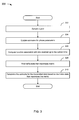
- FIG. 3 depicts a flowchart of an example of a demodulation process based on phase/frequency tracking and a trellis search.
- FIGS. 4A and 4B depict flowcharts of examples of methods for reducing ML detector complexity through per-survivor processing.
- FIG. 5 depicts a diagram of an example of mapping an ML path to bit estimates.
- FIG. 6 depicts a diagram of an example of a trellis and survivor path computation between the i ⁇ 1th and ith stage.
- FIGS. 7A and 7B depict flowcharts of examples of methods for reducing ML detector complexity through per-survivor processing.
- the memory in the information carrying phase is of length L ⁇ 1, since at time t the phase depends on the current data bit as well as the previous L ⁇ 1 data bits.
- the phase response is the integral of the frequency response g(t), i.e.
- the complex baseband transmitted signal can be written as
- a technique for detecting transmitted data with low complexity involves estimating unknown parameters and then using them in a trellis search to estimate the transmitted data.
- the trellis may or may not be a reduced state trellis.
- FIG. 1 depicts a flowchart 100 of an example of a method for detecting transmitted data with low complexity.
- the method is organized as a sequence of modules in the flowchart 100 .
- these and modules associated with other methods described herein may be reordered for parallel execution or into different sequences of modules.
- the flowchart 100 starts at module 102 with modeling modulation based upon a trellis.
- the modeling may or may not be accomplished in real time.
- the modeling may take place beforehand, and the remaining modules ( 104 - 108 ) of the flowchart 100 may take place in real-time or near-real-time.
- the flowchart 100 continues to module 104 where unknown parameters are estimated.
- both the phase offset ⁇ 0 and/or the frequency offset ⁇ ⁇ in the received signal are unknown.
- Let ⁇ circumflex over ( ⁇ ) ⁇ 0 and ⁇ circumflex over ( ⁇ ) ⁇ ⁇ denote the estimates for the phase offset ⁇ 0 and frequency offset ⁇ ⁇ , respectively. These estimates may be obtained from estimation algorithms applied to training sequences or preambles in the data prior to demodulation, data-driven estimation as described later with reference to FIGS. 3 , 4 A, 4 B, 7 A, and 7 B, or using other applicable known or convenient estimation techniques.
- a modulation index may or may not need to be approximated.
- the modulation index could be either explicit, approximated, or obviated.
- restricting the modulation index to these values allows coherent maximum-likelihood demodulation through a recursive updating of just a few parameters.
- the flowchart 100 continues to module 106 where a maximum-likelihood path through a trellis is selected.
- ⁇ ( ⁇ ,b[n ⁇ 1],b[n]) there are only four different values for ⁇ ( ⁇ ,b[n ⁇ 1],b[n]) and also that the phase is slightly different over the first bit time and the last bit time due to the lack of a previous bit for the first bit time and the lack of a subsequent bit for the last bit time.
- the phase of a received signal over any bit period (n ⁇ 1)T ⁇ t ⁇ nT depends only on d[n ⁇ 2], b[n ⁇ 1], and b[n], i.e.
- the transition from the trellis state at the (n ⁇ 1)th stage to the nth stage is determined by whether b[n] is a 0 or 1 bit, as depicted in FIG. 2 .
- the maximum-likelihood bit decision ⁇ tilde over (b) ⁇ [n] is determined by the transition from Stage n ⁇ 1 to Stage n.
- the flowchart 100 continues to module 108 where the maximum likelihood path is mapped to an output bit sequence. Having provided low complexity detection of transmitted data, the flowchart 100 ends.
- FIG. 2 depicts an example of a trellis diagram 200 for GFSK with 2p states.
- the number of states i.e., 2p
- the number of states is based upon d[n ⁇ 2] and b[n ⁇ 1], as described previously.
- FIG. 3 depicts a flowchart 300 of an example of a demodulation process based on phase/frequency tracking and a trellis search.
- the flowchart 300 starts at module 302 with sampling a signal.
- the received signal is sampled N times over a bit period, where N is a design parameter with a minimum value of 1 (1 sample per bit period). For the received signal over the ith bit period, these samples are averaged to obtain
- phase parameters may include, by way of example but not limitation, phase and frequency offsets.
- the demodulation process for a sequence of L transmitted bits proceeds as follows. Over each bit time iT the received signal is used to compute r[i] and obtain estimates for the phase and frequency offsets, ⁇ circumflex over ( ⁇ ) ⁇ 0 [i] and ⁇ circumflex over ( ⁇ ) ⁇ ⁇ [i], respectively.
- estimates may be obtained, by way of example but not limitation, from a preamble prior to bit transmission, through maximum-likelihood or maximum a posteriori estimation, or through a recursive updating at each bit time based on prior estimates and the received signal over the ith bit period.
- the recursive update can be simplified by making it a function of r[i] instead of the entire received signal over the ith bit time.
- the flowchart 300 continues to module 306 where a function associated with bits received up to the current time is computed.
- a sampled average for ⁇ [m i (t)] over the ith bit period is given by
- ⁇ [m i ] in terms of the ith data bit and the state of the trellis shown in FIG. 2 at stage i.
- the flowchart 300 continues to module 308 where a trellis state that maximizes the metric is found.
- metrics are computed at each stage, but the bit decisions can be made at each stage, or the decision can be delayed until all of the computations, at each stage, have been made. Waiting until the end to maximize the metric and output the corresponding bits introduces delay, but can result in a more optimal path, which tends to improve performance. Performing the maximization at each time i and outputting the bits associated with the trellis path with the maximum metric at time i, on the other hand, has the advantage of reduced delay and lower memory requirements.
- the flowchart 300 ends at module 310 where an estimate for the transmitted data based on the trellis state that maximizes the metric is determined.
- the detected data is thus a sequence ⁇ tilde over (b) ⁇ [0], . . . , ⁇ tilde over (b) ⁇ [L ⁇ 1] that maximizes the maximum-likelihood metric ⁇ [i] for each time i, or at time L ⁇ 1 at the end of the sequence of bit transmissions.
- FIGS. 4A and 4B depict flowcharts of examples of methods for reducing ML detector complexity through per-survivor processing.
- the complexity and memory requirements of the ML detector corresponding to the metric, ⁇ [L ⁇ 1], can be substantially reduced through per-survivor processing. This reduces the number of states in the trellis of FIG. 2 from 2p to 2.
- FIG. 4A is intended to show per-survivor processing where output is at the end of the process.
- the flowchart 400 A starts at module 402 where a trellis stage is initialized to ⁇ 1.
- the flowchart 400 A continues to module 404 where the trellis stage is incremented.
- d[i ⁇ 2] Over the ith bit time we compute d[i ⁇ 2] based on past bit decisions up until time i ⁇ 2. If d[i ⁇ 2] is fixed then the current bit decision only depends on this fixed value and the 2 possible values for the previous bit value b[i ⁇ 1].
- the trellis to determine b[i] has just 2 states, which we will denote as states 0 and 1. For this trellis let ⁇ y [i] ⁇ 0,1 ⁇ denote the start state of the survivor path in trellis section i that ends in state y ⁇ 0,1 ⁇ .
- the flowchart 400 A continues to module 405 where the received signal is sampled and averaged. For the received signal over the Rh bit period, the samples are averaged to obtain
- time-varying phase parameters may include, by way of example but not limitation, the phase offset and/or frequency offset.
- the phase and frequency offsets ⁇ circumflex over ( ⁇ ) ⁇ 0 [i] and ⁇ circumflex over ( ⁇ ) ⁇ ⁇ [i] are estimated. It may be noted that the time-varying phase parameters are not affected by data values, but rather by hardware variations, temperature, propagation environment, and/or other factors.
- the flowchart 400 A continues to module 410 where a metric is computed based on recursive updates of data functions and the time-varying phase parameters.
- the flowchart 400 A continues to module 412 where a survivor branch into each trellis state is determined.
- the flowchart 400 A continues to decision point 416 where it is determined whether a metric 0 (e.g., ⁇ 0 ) is greater than a metric 1 (e.g., ⁇ 1 ). If it is determined that the metric 0 is greater than the metric 1, then the flowchart 400 A continues to module 418 where the L ⁇ 1 bits for the survivor path into State 0 at time L ⁇ 1 are demodulated. In other words, if ⁇ 0 [L ⁇ 1]> ⁇ 1 [L ⁇ 1], the surviving path into State 0 at time L ⁇ 1 is assumed to be the ML path.
- a metric 0 e.g., ⁇ 0
- a metric 1 e.g., ⁇ 1
- the flowchart 400 A continues to module 420 where the L ⁇ 1 bits for the survivor path into State 0 at time L ⁇ 1 are demodulated.
- the surviving path into State 1 at time L ⁇ 1 is assumed to be the ML path.
- the bit ⁇ tilde over (b) ⁇ [i] corresponding to the survivor path into State 0 is ⁇ 0 [i+1] and the bit corresponding to the survivor path into State 1 is ⁇ 1 [i+1].
- the bit sequences up to time i ⁇ 1 corresponding to the survivor paths at time i are updated at each time interval and the demodulated bit sequence then corresponds to the ML trellis path at time L ⁇ 1.
- FIG. 4B illustrates per-survivor processing with output at each stage of the trellis. This reduces memory requirements and delay by outputting the bit associated with the survivor path at time i for the state x[i] ⁇ 0,1 ⁇ with the largest metric ⁇ x [i]. Specifically, at time i, the flowchart traces back some K of stages in the trellis and outputs the bit b[i ⁇ K] corresponding to the path for state x[i] ⁇ 0,1 ⁇ with the largest metric ⁇ x [i] at time i. Typically, 1 ⁇ K ⁇ L.
- the modules 452 - 462 are quite similar to modules 402 - 412 , so they are not re-described here.
- the flowchart 400 B continues from the module 462 to the decision point 464 where it is determined whether a metric 0 greater than a metric 1. If it is determined that the metric 0 is greater than the metric 1, then the flowchart 400 B continues to module 466 where the bit ⁇ tilde over (b) ⁇ [i ⁇ K] for the survivor path associated with State 0 at time i is output.
- the flowchart 400 B continues to module 472 where any remaining bits along the survivor path with the maximum metric are demodulated. For example, if you go back K stages, then you output K bits. In an illustrative embodiment, the bits b[L ⁇ K] to b[L ⁇ 1] are output. After module 472 , the flowchart 400 B ends.
- FIG. 5 depicts a diagram 500 of an example of mapping an ML path to bit estimates.
- FIG. 6 depicts a diagram 600 of an example of a trellis and survivor path computation between the i ⁇ 1th and ith stage.
- solid branches correspond to surviving paths (note there is only one entering each state at any trellis stage) and dashed branches corresponds to not yet decided survivor path entering State 0 at trellis stage i. If ⁇ 1 [i ⁇ 1]+ ⁇ 1 ⁇ 0 [i]> ⁇ 0 [i ⁇ 1]+ ⁇ 0 ⁇ 0 [i], the surviving branch entering State 0 in trellis section i starts in State 1 and ends in State 0.
- phase is slightly different over the first and last bit times since the phase over the first bit time does not have memory associated with the previous bit, and the phase over the last bit time does not have memory associated with a subsequent bit.
- phases corresponding to these first and last bit periods as ⁇ s ( ⁇ ,b[0]) and ⁇ e ( ⁇ ,b[L ⁇ 1]), respectively.
- the preamble processing will often take care of the first bit transmission and also provide an estimate of the phase offset ⁇ 0 . In this case z s (0) and z s (1) will never be used.
- ⁇ circumflex over ( ⁇ ) ⁇ 0 [i] denotes the phase offset estimate at time i
- this estimate depend only on ⁇ circumflex over ( ⁇ ) ⁇ 0 [i ⁇ 1]
- the frequency offset estimate at time i ⁇ circumflex over ( ⁇ ) ⁇ ⁇ [i] should depend only on ⁇ circumflex over ( ⁇ ) ⁇ ⁇ [i ⁇ 1].
- FIGS. 7A and 7B depict flowcharts 700 A and 700 B of examples of methods for reducing ML detector complexity through per-survivor processing.
- the flowcharts 700 A and 700 B are similar to the flowcharts 400 A and 400 B ( FIGS. 4A and 4B ), though different exemplary computations may be in order at certain of the steps.
- FIGS. 7A and 7B respectively refer to real data functions at modules 709 , 710 and 758 , 760 .
- the use of real data functions, instead of complex data functions can significantly reduce the complexity of the computations.
- a[i] ⁇ +1, ⁇ 1 ⁇ is the polar representation of the binary data.
- ⁇ [m i ] e j ⁇ hd[i ⁇ 2] z(a[i ⁇ 1],a[i]).
- DPSK also referred to as D-MPSK
- the information bits are mapped to the phases using Gray mapping.
- the transmitted baseband analog signal is given by
- the received base band signal is
- the DPSK signal can be demodulated by finding the maximum likelihood path through the trellis associated with the received signal, as has been described previously for GFSK (e.g., with reference FIG. 1 ).
- the transmit pulse can be truncated by using a window w(t) that is non-zero except N symbol intervals centered around zero
- h ⁇ ⁇ ( t ) ⁇ h ⁇ ( t ) ⁇ w ⁇ ( t ) - NT / 2 ⁇ t ⁇ NT / 2 0 elsewhere .
- This signal is averaged over the ith bit period to obtain
- the demodulation can be performed by a trellis search on a fully connected trellis with M states for the symbol z[i] that maximizes the maximum likelihood metric ⁇ [L ⁇ 1] for L ⁇ 1 symbols given by
- K ⁇ 0 is the trace back length that will also affect the delay of the decision.
- the starting state x can be put to the winning ending state from the previous trellis section, i.e.,
Abstract
Description
for h the modulation index, a[i]ε{+1,−1} the polar representation of the binary data bits, L the length of the signal memory, T the bit period, and q(t) the phase response. The memory in the information carrying phase is of length L−1, since at time t the phase depends on the current data bit as well as the previous L−1 data bits. The phase response is the integral of the frequency response g(t), i.e.
where g(t)=u(t)*hg(t) is the convolution of a rectangular pulse u(t) and a Gaussian pulse hg(t).
then the complex baseband received signal becomes r(t)=s(t)ejφ(t)+n(t)=ejψ(t,b)ejφ(t)+n(t), where s(t) is the complex baseband transmitted signal, n(t) is the complex baseband noise of the received signal, ψ(t,b) is the demodulated phase of the signal given by
the binary representation of the data, and φ(t)=φ0+2πΔƒt is the time-varying phase offset of the received signal, which depends on a fixed phase offset φ0 and a frequency offset Δƒ, and is thus independent of the data.
Note that ρ[mi] can be rewritten as
for vi=[vi[1],vi[2],vi[3]]=[d[i−2],b[i−1],b[i]]. Thus, we can express ρ[mi] in terms of the ith data bit and the state of the trellis shown in
where ρ*[{tilde over (m)}i] denotes the complex conjugate of ρ[{tilde over (m)}i].
for c=μx[i−1] and
Note that dμ
so that we can express the metrics for the first trellis stage as
where e−j{circumflex over (φ)}
The decisions on the last information bit is {tilde over (b)}[L−1]=x if Λx[L−1]>Λy[L−1] and the remaining bit decisions are made according to {tilde over (b)}[i]=μ{tilde over (b)}[i+1][i+1] for i=0,1, 2, . . . , L−2.
where again a[i]ε{+1,−1} is the polar representation of the binary data. Then ρ[mi]=ejπhd[i−2]z(a[i−1],a[i]).
where p[i]=βp[i−1]+(1−β)r[i]ρ*[{tilde over (m)}i]ρ[{tilde over (m)}i−1]r*[i−1], and 0≦β≦1 is the forgetting factor. The branch metric for trellis section i in (6) can now be approximated by λ[i]=Re{r[i]ρ*[{tilde over (m)}i]q*[i−1]}, where q[i] is the combined phase and frequency offset estimate according to
| for i = 1 : L (for all trellis sections) |
| for y = 0 : 1 (for all ending states) |
| for x = 0 : 1 (for all starting states) |
| ū′x = [ |
| Λ′x = Λx[i − 1] + cos(π(ū′x − |
| end |
| if Λ′1 > Λ′0 (finding the winning starting state) |
| μy[i] = 1 |
| δy[i] = [δ1[i − 1] + h]−1 +1 |
| Λy[i] = Λ′1 |
| ūy[i] = ū′1 |
| |
| |
| else |
| μy[i] = 0 |
| δy[i] = [δ0[i − 1] − h]−1 +1 |
| Λy[i] = Λ′0 |
| ūy[i] = ū′0 |
| |
| |
| end |
| end |
| if Λ1[i] > Λ0[i] (trace back decision by K=1 and normalization of metric) |
| Λ0[i] = Λ0[i] − Λ1[i] |
| Λ1[i] = Λ1[i] − Λ1[i] = 0 |
| {circumflex over (b)}[i − 1] = μ1[i] |
| else |
| Λ1[i] = Λ1[i] − Λ0[i] |
| Λ0[i] = Λ0[i] − Λ0[i] = 0 |
| {tilde over (b)}[i − 1] = μ0[i] |
| end |
| end |
In an illustrative embodiment, the information bits are mapped to the phases using Gray mapping. The first symbol s[0]=ejπφ[0] is transmitted with an arbitrary phase φ[0]ε[−1,+1). The transmitted symbols can also be written as s[i]=ejπ(Φ[i]+φ[0])=ejπΦ[i]ejπφ[0], where Φ[i]εS denotes the coherent data phases with
Note that φ[i]=Φ[i]−Φ[i−1], for i=1, 2, . . . , L. The transmitted baseband analog signal is given by
where h(t) is the transmit pulse shaping and T is the data symbol duration. The received base band signal is
where τ is the unknown propagation delay, Δ is the unknown frequency offset, θ=φ[0]−2Δτ is the unknown phase offset, and n(t) is the additive white Gaussian noise with two sided power spectral density
There may or may not be unknown parameters associated with, for example, the signal. The DPSK signal can be demodulated by finding the maximum likelihood path through the trellis associated with the received signal, as has been described previously for GFSK (e.g., with reference
Using {tilde over (h)}(t) as the transmit pulse, the received signal becomes
This signal is averaged over the ith bit period to obtain
Assuming perfect timing, the demodulation can be performed by a trellis search on a fully connected trellis with M states for the symbol z[i] that maximizes the maximum likelihood metric Λ[L−1] for L−1 symbols given by
Using the same notation as for GFSK, described previously, define
| for i = 1:L (for all trellis sections) |
| for y = 0:M − 1 (for all ending states) |
| for x = 0:M − 1 (for all starting states) |
|
|
|
|
|
| end | |
|
|
|
|
|
|
|
|
|
|
|
|
|
|
|
|
|
| end | |
|
|
|
| for y = 0:M − 1 (normalize the metric to prevent overflow) |
|
|
| end | |
| for k = i : −1:i − K (trace back in the trellis) |
|
|
|
|
|
| end | |
|
|
| end |
That will reduce the innermost for-loop with a factor of M.
Claims (18)
Priority Applications (1)
| Application Number | Priority Date | Filing Date | Title |
|---|---|---|---|
| US11/800,357 US8090060B2 (en) | 2006-05-04 | 2007-05-04 | Demodulation technique for GFSK and DPSK |
Applications Claiming Priority (3)
| Application Number | Priority Date | Filing Date | Title |
|---|---|---|---|
| US79795606P | 2006-05-04 | 2006-05-04 | |
| US81003606P | 2006-05-31 | 2006-05-31 | |
| US11/800,357 US8090060B2 (en) | 2006-05-04 | 2007-05-04 | Demodulation technique for GFSK and DPSK |
Publications (2)
| Publication Number | Publication Date |
|---|---|
| US20070268980A1 US20070268980A1 (en) | 2007-11-22 |
| US8090060B2 true US8090060B2 (en) | 2012-01-03 |
Family
ID=38668334
Family Applications (2)
| Application Number | Title | Priority Date | Filing Date |
|---|---|---|---|
| US11/800,357 Active 2030-02-03 US8090060B2 (en) | 2006-05-04 | 2007-05-04 | Demodulation technique for GFSK and DPSK |
| US12/299,470 Active 2029-03-04 US8446998B2 (en) | 2006-05-04 | 2007-05-04 | Multiple antenna receiver system and method |
Family Applications After (1)
| Application Number | Title | Priority Date | Filing Date |
|---|---|---|---|
| US12/299,470 Active 2029-03-04 US8446998B2 (en) | 2006-05-04 | 2007-05-04 | Multiple antenna receiver system and method |
Country Status (3)
| Country | Link |
|---|---|
| US (2) | US8090060B2 (en) |
| TW (1) | TWI411255B (en) |
| WO (1) | WO2007130578A2 (en) |
Cited By (1)
| Publication number | Priority date | Publication date | Assignee | Title |
|---|---|---|---|---|
| US20160020738A1 (en) * | 2014-07-16 | 2016-01-21 | Samsung Electronics Co., Ltd. | Diversity amp module and apparatus comprising the same |
Families Citing this family (40)
| Publication number | Priority date | Publication date | Assignee | Title |
|---|---|---|---|---|
| US7076228B1 (en) * | 1999-11-10 | 2006-07-11 | Rilling Kenneth F | Interference reduction for multiple signals |
| US8363744B2 (en) | 2001-06-10 | 2013-01-29 | Aloft Media, Llc | Method and system for robust, secure, and high-efficiency voice and packet transmission over ad-hoc, mesh, and MIMO communication networks |
| KR100587978B1 (en) * | 2004-11-29 | 2006-06-08 | 한국전자통신연구원 | Apparatus and method for blind modulation classification in satellite communication system |
| US8064835B2 (en) | 2006-01-11 | 2011-11-22 | Quantenna Communications, Inc. | Antenna assignment system and method |
| WO2007130578A2 (en) | 2006-05-04 | 2007-11-15 | Quantenna Communications, Inc. | Multiple antenna receiver system and method |
| US8091012B2 (en) | 2006-05-04 | 2012-01-03 | Quantenna Communications Inc. | System and method for decreasing decoder complexity |
| US8063839B2 (en) | 2006-10-17 | 2011-11-22 | Quantenna Communications, Inc. | Tunable antenna system |
| EP2095539B1 (en) * | 2006-12-20 | 2011-02-09 | Astrium Limited | Beamforming system and method |
| US7844008B2 (en) * | 2006-12-28 | 2010-11-30 | Nokia Corporation | Delayed branch decision in quadrature decomposition with M-searching |
| WO2009054938A1 (en) | 2007-10-19 | 2009-04-30 | Quantenna Communications, Inc. | Mitigating interference in a coded communication system |
| KR101231912B1 (en) * | 2008-08-26 | 2013-02-08 | 삼성전자주식회사 | method and transmitter for modifying beamforming vector iteratively |
| US9083573B2 (en) | 2008-10-15 | 2015-07-14 | Stmicroelectronics Asia Pacific Pte. Ltd. | Simultaneous transmission of signals, such as orthogonal-frequency-division-multiplexed (OFDM) signals, that include a same frequency |
| US9130789B2 (en) | 2008-10-15 | 2015-09-08 | Stmicroelectronics Asia Pacific Pte. Ltd. | Recovering data from a secondary one of simultaneous signals, such as orthogonal-frequency-division-multiplexed (OFDM) signals, that include a same frequency |
| US9338033B2 (en) * | 2008-10-15 | 2016-05-10 | Stmicroelectronics, Inc. | Recovering data from a primary one of simultaneous signals, such as orthogonal-frequency-division-multiplexed (OFDM) signals, that include a same frequency |
| FR2947401B1 (en) * | 2009-06-26 | 2012-07-13 | Thales Sa | MULTI-ANTENNA COMMUNICATION SYSTEM |
| US8401134B1 (en) * | 2009-09-30 | 2013-03-19 | The United States Of America As Represented By The Secretary Of The Navy | Broadband high dynamic range digital receiving system for electromagnetic signals |
| US8824526B2 (en) * | 2010-02-18 | 2014-09-02 | Intel Mobile Communications GmbH | Apparatus and method for antenna diversity reception |
| US9020074B2 (en) | 2010-02-18 | 2015-04-28 | Intel Mobile Communications GmbH | Apparatus and method for antenna diversity reception |
| BR112012023425A2 (en) * | 2010-03-17 | 2016-06-07 | Ericsson Telefon Ab L M | method and device for transmitting signals in a gsm system |
| US10050680B2 (en) * | 2010-06-07 | 2018-08-14 | Entropic Communications, Llc | Method and apparatus for real time multiplexing with transmitter and antenna array elements |
| US8477885B2 (en) * | 2011-01-21 | 2013-07-02 | Northrop Grumman Systems Corporation | Recursive frequency estimation |
| WO2012107797A1 (en) | 2011-02-07 | 2012-08-16 | Nokia Corporation | Processing samples of a received rf signal |
| JP5803429B2 (en) * | 2011-08-25 | 2015-11-04 | 富士通株式会社 | Receiver |
| CN103856255B (en) * | 2012-12-04 | 2017-06-06 | 华为终端有限公司 | Signal of communication processing method and its terminal |
| US9306781B2 (en) * | 2014-04-01 | 2016-04-05 | Samsung Electronics Co., Ltd | Apparatus and method for receiving signal in communication system supporting Gaussian frequency shift keying modulation scheme |
| US9432065B2 (en) * | 2014-10-02 | 2016-08-30 | Entropic Communications, Llc | Communication transceiver interface |
| TWI530186B (en) * | 2014-12-26 | 2016-04-11 | 絡達科技股份有限公司 | Tuner and method for crosstalk cancellation |
| CN104639855A (en) * | 2014-12-26 | 2015-05-20 | 络达科技股份有限公司 | Tuning device and method capable of eliminating interactive interferences |
| KR20170133550A (en) * | 2016-05-25 | 2017-12-06 | 삼성전자주식회사 | Receiver and detecting method of thereof |
| CN107872408B (en) * | 2016-09-23 | 2021-01-22 | 北京大学(天津滨海)新一代信息技术研究院 | Multi-tap radio frequency interference eliminator based on surface acoustic wave device |
| US11165521B2 (en) * | 2016-12-13 | 2021-11-02 | Amimon Ltd. | Analog signal transmission with multiple antennas |
| US10419063B2 (en) | 2016-12-30 | 2019-09-17 | Waviot Integrated Systems, Llc | Method and system for receiving telemetry messages over RF channel |
| US10326556B2 (en) | 2016-12-30 | 2019-06-18 | Waviot Integrated Systems, Llc | Method and system of frequency correction in LPWAN networks |
| WO2018126204A1 (en) | 2016-12-30 | 2018-07-05 | Waviot Integrated Systems, Llc | Simultaneous confirmation of many messages in lpwan & frequency correction for data transmission |
| US10257009B2 (en) | 2016-12-30 | 2019-04-09 | Waviot Integrated Systems, Llc | Method for multichannel signal search and demodulation and technique to demodulate and detect DBPSK FDMA ultra-narrow band signal |
| US10377444B2 (en) * | 2017-07-31 | 2019-08-13 | Shimano Inc. | Bicycle electric component |
| US11139590B2 (en) * | 2020-01-16 | 2021-10-05 | U-Blox Ag | Adaptive single-element antenna apparatus and method of operating same |
| US11277289B1 (en) * | 2020-11-25 | 2022-03-15 | Dialog Semiconductor B.V. | Demodulation unit and method for demodulating a DPSK signal |
| CN112688894B (en) * | 2020-12-23 | 2022-05-13 | 大唐半导体科技有限公司 | Viterbi demodulation algorithm and apparatus applied to GFSK system |
| CN113098811B (en) * | 2021-04-01 | 2022-06-28 | 高拓讯达(北京)科技有限公司 | Demodulation decoding method and demodulation decoding device for GFSK (Gaussian filtered Shift keying) signals |
Citations (64)
| Publication number | Priority date | Publication date | Assignee | Title |
|---|---|---|---|---|
| US5268695A (en) | 1992-10-06 | 1993-12-07 | Trimble Navigation Limited | Differential phase measurement through antenna multiplexing |
| US5729558A (en) * | 1995-03-08 | 1998-03-17 | Lucent Technologies Inc. | Method of compensating for Doppler error in a wireless communications system, such as for GSM and IS54 |
| US6035007A (en) | 1996-03-12 | 2000-03-07 | Ericsson Inc. | Effective bypass of error control decoder in a digital radio system |
| US6081700A (en) | 1996-12-17 | 2000-06-27 | Motorola, Inc. | Radio having a self-tuning antenna and method thereof |
| US6351499B1 (en) | 1999-12-15 | 2002-02-26 | Iospan Wireless, Inc. | Method and wireless systems using multiple antennas and adaptive control for maximizing a communication parameter |
| US6470047B1 (en) | 2001-02-20 | 2002-10-22 | Comsys Communications Signal Processing Ltd. | Apparatus for and method of reducing interference in a communications receiver |
| US6477208B1 (en) * | 1997-10-30 | 2002-11-05 | Comtier | Composite trellis system and method |
| US6477213B1 (en) | 1998-05-28 | 2002-11-05 | Matsushita Electric Industrial Co., Ltd. | Base station apparatus and radio communication method |
| US20020163879A1 (en) | 2001-01-19 | 2002-11-07 | Xiaodong Li | Multi-carrier communication with time division multiplexing and carrier-selective loading |
| US6484285B1 (en) | 2000-02-07 | 2002-11-19 | Ericsson, Inc. | Tailbiting decoder and method |
| US20030003863A1 (en) | 2001-05-04 | 2003-01-02 | Jorn Thielecke | Link adaptation for MIMO transmission schemes |
| US20030081701A1 (en) | 2001-10-26 | 2003-05-01 | Kobby Pick | Metric correction for multi user detection, for long codes DS-CDMA |
| US20030087673A1 (en) | 2001-05-16 | 2003-05-08 | Walton Jay R. | Method and apparatus for allocating downlink resources in a multiple-input multiple-output (MIMO) communication system |
| US20030141938A1 (en) * | 2002-01-30 | 2003-07-31 | The Aerospace Corporation | Quadrature vestigial sideband digital communications method |
| US20030157954A1 (en) | 2002-02-19 | 2003-08-21 | Irina Medvedev | Power control for partial channel-state information (CSI) multiple-input, multiple-output (MIMO) systems |
| US20030185309A1 (en) | 2001-04-07 | 2003-10-02 | Pautler Joseph J. | Method and system in a transceiver for controlling a multiple-input, multiple-output communications channel |
| US6642904B2 (en) | 2000-10-31 | 2003-11-04 | Mitsubishi Materials Corporation | Antenna |
| US20040013209A1 (en) * | 2001-05-17 | 2004-01-22 | Ephi Zehavi | GFSK receiver |
| US20040153679A1 (en) | 2002-11-20 | 2004-08-05 | Kabushiki Kaisha Toshiba | Reduced power consumption signal processing methods and apparatus |
| US6807404B2 (en) | 2000-04-25 | 2004-10-19 | Siemens Ag | Antenna diversity receiver with variable switching delay time |
| US20040234012A1 (en) | 2002-06-24 | 2004-11-25 | Rooyen Pieter Van | Reduced-complexity antenna system using multiplexed receive chain processing |
| US20040240486A1 (en) | 2003-05-30 | 2004-12-02 | Narasimhan Venkatesh | Flexible multi-channel multi-thread media access controller and physical layer interface for wireless networks |
| US20050053172A1 (en) | 2003-09-10 | 2005-03-10 | Nokia Corporation | Method and apparatus providing an advanced MIMO receiver that includes a signal-plus-residual-interference (SPRI) detector |
| US6871052B2 (en) | 2000-07-05 | 2005-03-22 | Koninklijke Philips Electronics N.V. | Antenna diversity receiver |
| US20050085269A1 (en) | 2002-04-30 | 2005-04-21 | Soodesh Buljore | Wireless communication using multi-transmit multi-receive antenna arrays |
| US20050099937A1 (en) | 2003-11-12 | 2005-05-12 | Samsung Electronics Co., Ltd. | Apparatus and method for sub-carrier allocation in a multiple-input and multiple-output (MIMO) orthogonal frequency division multiplexing (OFDM) communication system |
| US20050113041A1 (en) | 2003-11-26 | 2005-05-26 | Texas Instruments Incorporated | Frequency-domain subchannel transmit antenna selection and power pouring for multi-antenna transmission |
| US20050170839A1 (en) | 2004-02-04 | 2005-08-04 | Nokia Corporation | Variable bandwidth in a communication system |
| US20050192019A1 (en) | 2004-02-17 | 2005-09-01 | Samsung Electronics Co., Ltd. | Apparatus and method for transmitting and receiving data in multiuser MIMO system |
| US20050195784A1 (en) | 2004-03-05 | 2005-09-08 | Ramot At Tel Aviv University Ltd. | Antenna divison multiple access |
| US20050220057A1 (en) | 1999-06-01 | 2005-10-06 | Peter Monsen | Multiple access system and method for multibeam digital radio systems |
| US20050245201A1 (en) | 2004-04-30 | 2005-11-03 | Nokia Corporation | Front-end topology for multiband multimode communication engines |
| US6967598B2 (en) | 2004-02-20 | 2005-11-22 | Bae Systems Information And Electronic Systems Integration Inc | Reduced complexity multi-turbo multi-user detector |
| US20050265470A1 (en) | 2002-12-05 | 2005-12-01 | Matsushita Electric Industrial Co., Ltd. | Radio communication system, radio communication method, and radio communication device |
| US20050276361A1 (en) | 2004-06-10 | 2005-12-15 | Samsung Electronics Co., Ltd. | Interference power measurement apparatus and method for space-time beam forming |
| US20060034221A1 (en) | 2004-08-13 | 2006-02-16 | Jeyhan Karaoguz | Multi-dimensional network resource allocation |
| US20060034217A1 (en) | 2004-08-11 | 2006-02-16 | Samsung Electronics Co., Ltd. | Method and network device for enabling MIMO station and SISO station to coexist in wireless network without data collision |
| US20060083290A1 (en) * | 2004-10-19 | 2006-04-20 | Shin Cheol H | Frequency estimation method of MB-OFDM UWB system using time frequency hopping strategy |
| US7035343B2 (en) * | 2002-01-31 | 2006-04-25 | Qualcomm Inc. | Closed loop transmit diversity antenna verification using trellis decoding |
| US20060094385A1 (en) | 2004-11-04 | 2006-05-04 | Hamid Rafati | Architecture for multiple-antenna systems |
| US7058422B2 (en) * | 2000-09-20 | 2006-06-06 | Bae Systems Information And Electronic Systems Integration Inc. | Method for overusing frequencies to permit simultaneous transmission of signals from two or more users on the same frequency and time slot |
| US20060223487A1 (en) | 2005-04-04 | 2006-10-05 | Freescale Semiconductor, Inc. | Multi-band mixer and quadrature signal generator for a multi-mode radio receiver |
| US20060270427A1 (en) | 2005-05-30 | 2006-11-30 | Masaaki Shida | Wireless transceiver |
| US20060276227A1 (en) | 2005-06-02 | 2006-12-07 | Qualcomm Incorporated | Multi-antenna station with distributed antennas |
| WO2007021159A2 (en) | 2005-08-19 | 2007-02-22 | Samsung Electronics Co., Ltd. | Cinr estimating method and device using preamble in ofdm |
| US7194237B2 (en) | 2002-07-30 | 2007-03-20 | Ipr Licensing Inc. | System and method for multiple-input multiple-output (MIMO) radio communication |
| US7224743B2 (en) | 2003-04-24 | 2007-05-29 | Northrop Grumman Corporation | Efficient decoding of trellis coded modulation waveforms |
| US20070136446A1 (en) | 2005-12-01 | 2007-06-14 | Behrooz Rezvani | Wireless media server system and method |
| US20070153924A1 (en) | 2006-01-03 | 2007-07-05 | Fuyun Ling | Methods and apparatus for noise estimation in a communication system |
| US20070202818A1 (en) | 2004-09-27 | 2007-08-30 | Naoki Okamoto | Radio Transmission Device |
| US20070230638A1 (en) | 2006-03-30 | 2007-10-04 | Meir Griniasty | Method and apparatus to efficiently configure multi-antenna equalizers |
| US20070258534A1 (en) * | 2004-09-28 | 2007-11-08 | Rohde & Schwarz Gmbh & Co. Kg | Method and Device for Synchronizing the Carrier Frequency of an Offset Quadrature Phase-Modulated Signal |
| WO2007130578A2 (en) | 2006-05-04 | 2007-11-15 | Quantenna Communications, Inc. | Multiple antenna receiver system and method |
| US7298798B1 (en) * | 2001-08-24 | 2007-11-20 | Mediatek, Inc. | Method and system for decoding block codes |
| US7321636B2 (en) | 2001-05-31 | 2008-01-22 | Magnolia Broadband Inc. | Communication device with smart antenna using a quality-indication signal |
| US20080139123A1 (en) | 2006-12-06 | 2008-06-12 | Chungyeol Paul Lee | Method and System for Single Chip WLAN and Bluetooth Radios on a Single CMOS Substrate |
| US20080159123A1 (en) | 2003-10-08 | 2008-07-03 | Tehrani Ardavan M | Apparatus And Method Of Multiple Antenna Receiver Combining Of High Data Rate Wideband Packetized Wireless Communication Signals |
| US7400872B2 (en) | 2004-06-03 | 2008-07-15 | Oki Electric Industry Co., Ltd. | Radio receiver for selecting appropriate diversity antennas by comparing correlation values and a method for the same |
| US7415079B2 (en) | 2000-09-12 | 2008-08-19 | Broadcom Corporation | Decoder design adaptable to decode coded signals using min* or max* processing |
| US7450657B2 (en) | 2005-08-18 | 2008-11-11 | Beceem Communications Inc. | Antenna virtualization in communication systems |
| US7533327B2 (en) | 2006-03-07 | 2009-05-12 | Broadcom Corporation | Method and system for bluetooth decoding |
| US7564931B2 (en) * | 2005-05-10 | 2009-07-21 | Seagate Technology Llc | Robust maximum-likelihood based timing recovery |
| US7623836B1 (en) | 2003-06-19 | 2009-11-24 | Intel Corporation | Antenna selection for multicarrier communications |
| US20100091891A1 (en) | 2008-10-10 | 2010-04-15 | Wipro Limited | Link quality metric based antenna selection for transceivers |
Family Cites Families (16)
| Publication number | Priority date | Publication date | Assignee | Title |
|---|---|---|---|---|
| JP2728547B2 (en) * | 1990-06-13 | 1998-03-18 | 株式会社日立製作所 | Diversity receiver |
| GB9019487D0 (en) * | 1990-09-06 | 1990-10-24 | Ncr Co | Carrier detection for a wireless local area network |
| US5266695A (en) * | 1991-03-12 | 1993-11-30 | Edison Polymer Innovation Corporation | Composite densification with benzoxazines |
| US6032033A (en) * | 1996-12-03 | 2000-02-29 | Nortel Networks Corporation | Preamble based selection diversity in a time division multiple access radio system using digital demodulation |
| US7079584B2 (en) * | 1998-08-10 | 2006-07-18 | Kamilo Feher | OFDM, CDMA, spread spectrum, TDMA, cross-correlated and filtered modulation |
| WO2001069824A1 (en) * | 2000-03-14 | 2001-09-20 | Vyyo, Ltd. | Low-complexity beam forming and antenna diversity receiver |
| EP1502364A4 (en) * | 2002-04-22 | 2010-03-31 | Ipr Licensing Inc | Multiple-input multiple-output radio transceiver |
| US20050036575A1 (en) * | 2003-08-15 | 2005-02-17 | Nokia Corporation | Method and apparatus providing low complexity equalization and interference suppression for SAIC GSM/EDGE receiver |
| US7127013B2 (en) * | 2003-08-18 | 2006-10-24 | Airgo Networks, Inc. | Spacetime equalization in a wireless receiver |
| EP3340488B1 (en) * | 2003-10-01 | 2020-02-19 | Avago Technologies International Sales Pte. Limited | System and method for antenna selection |
| JP4336760B2 (en) * | 2004-01-14 | 2009-09-30 | 日本電気株式会社 | Diversity receiver and antenna switching control method |
| US8077691B2 (en) * | 2004-03-05 | 2011-12-13 | Qualcomm Incorporated | Pilot transmission and channel estimation for MISO and MIMO receivers in a multi-antenna system |
| TWI237453B (en) * | 2004-05-11 | 2005-08-01 | Realtek Semiconductor Corp | Method and apparatus for antenna diversity |
| US9089003B2 (en) * | 2004-07-28 | 2015-07-21 | Broadcom Corporation | Quality-of-service (QoS)-based delivery of multimedia call sessions using multi-network simulcasting |
| US8098776B2 (en) * | 2004-10-06 | 2012-01-17 | Broadcom Corporation | Method and system for pre-equalization in a single weight spatial multiplexing MIMO system |
| US7801248B2 (en) * | 2004-11-19 | 2010-09-21 | Qualcomm Incorporated | Interference suppression with virtual antennas |
-
2007
- 2007-05-04 WO PCT/US2007/010845 patent/WO2007130578A2/en active Application Filing
- 2007-05-04 TW TW096116031A patent/TWI411255B/en active
- 2007-05-04 US US11/800,357 patent/US8090060B2/en active Active
- 2007-05-04 US US12/299,470 patent/US8446998B2/en active Active
Patent Citations (66)
| Publication number | Priority date | Publication date | Assignee | Title |
|---|---|---|---|---|
| US5268695A (en) | 1992-10-06 | 1993-12-07 | Trimble Navigation Limited | Differential phase measurement through antenna multiplexing |
| US5729558A (en) * | 1995-03-08 | 1998-03-17 | Lucent Technologies Inc. | Method of compensating for Doppler error in a wireless communications system, such as for GSM and IS54 |
| US6035007A (en) | 1996-03-12 | 2000-03-07 | Ericsson Inc. | Effective bypass of error control decoder in a digital radio system |
| US6081700A (en) | 1996-12-17 | 2000-06-27 | Motorola, Inc. | Radio having a self-tuning antenna and method thereof |
| US6477208B1 (en) * | 1997-10-30 | 2002-11-05 | Comtier | Composite trellis system and method |
| US6477213B1 (en) | 1998-05-28 | 2002-11-05 | Matsushita Electric Industrial Co., Ltd. | Base station apparatus and radio communication method |
| US20050220057A1 (en) | 1999-06-01 | 2005-10-06 | Peter Monsen | Multiple access system and method for multibeam digital radio systems |
| US6351499B1 (en) | 1999-12-15 | 2002-02-26 | Iospan Wireless, Inc. | Method and wireless systems using multiple antennas and adaptive control for maximizing a communication parameter |
| US6484285B1 (en) | 2000-02-07 | 2002-11-19 | Ericsson, Inc. | Tailbiting decoder and method |
| US6807404B2 (en) | 2000-04-25 | 2004-10-19 | Siemens Ag | Antenna diversity receiver with variable switching delay time |
| US6871052B2 (en) | 2000-07-05 | 2005-03-22 | Koninklijke Philips Electronics N.V. | Antenna diversity receiver |
| US7415079B2 (en) | 2000-09-12 | 2008-08-19 | Broadcom Corporation | Decoder design adaptable to decode coded signals using min* or max* processing |
| US7058422B2 (en) * | 2000-09-20 | 2006-06-06 | Bae Systems Information And Electronic Systems Integration Inc. | Method for overusing frequencies to permit simultaneous transmission of signals from two or more users on the same frequency and time slot |
| US6642904B2 (en) | 2000-10-31 | 2003-11-04 | Mitsubishi Materials Corporation | Antenna |
| US20020163879A1 (en) | 2001-01-19 | 2002-11-07 | Xiaodong Li | Multi-carrier communication with time division multiplexing and carrier-selective loading |
| US6470047B1 (en) | 2001-02-20 | 2002-10-22 | Comsys Communications Signal Processing Ltd. | Apparatus for and method of reducing interference in a communications receiver |
| US20030185309A1 (en) | 2001-04-07 | 2003-10-02 | Pautler Joseph J. | Method and system in a transceiver for controlling a multiple-input, multiple-output communications channel |
| US20030003863A1 (en) | 2001-05-04 | 2003-01-02 | Jorn Thielecke | Link adaptation for MIMO transmission schemes |
| US20030087673A1 (en) | 2001-05-16 | 2003-05-08 | Walton Jay R. | Method and apparatus for allocating downlink resources in a multiple-input multiple-output (MIMO) communication system |
| US20040013209A1 (en) * | 2001-05-17 | 2004-01-22 | Ephi Zehavi | GFSK receiver |
| US7321636B2 (en) | 2001-05-31 | 2008-01-22 | Magnolia Broadband Inc. | Communication device with smart antenna using a quality-indication signal |
| US7298798B1 (en) * | 2001-08-24 | 2007-11-20 | Mediatek, Inc. | Method and system for decoding block codes |
| US20030081701A1 (en) | 2001-10-26 | 2003-05-01 | Kobby Pick | Metric correction for multi user detection, for long codes DS-CDMA |
| US20030141938A1 (en) * | 2002-01-30 | 2003-07-31 | The Aerospace Corporation | Quadrature vestigial sideband digital communications method |
| US7035343B2 (en) * | 2002-01-31 | 2006-04-25 | Qualcomm Inc. | Closed loop transmit diversity antenna verification using trellis decoding |
| US20050130694A1 (en) | 2002-02-19 | 2005-06-16 | Irina Medvedev | Power control for partial channel-state information (CSI) multiple-input, multiple-output (MIMO) systems |
| US7076263B2 (en) | 2002-02-19 | 2006-07-11 | Qualcomm, Incorporated | Power control for partial channel-state information (CSI) multiple-input, multiple-output (MIMO) systems |
| US20030157954A1 (en) | 2002-02-19 | 2003-08-21 | Irina Medvedev | Power control for partial channel-state information (CSI) multiple-input, multiple-output (MIMO) systems |
| US20050085269A1 (en) | 2002-04-30 | 2005-04-21 | Soodesh Buljore | Wireless communication using multi-transmit multi-receive antenna arrays |
| US20040234012A1 (en) | 2002-06-24 | 2004-11-25 | Rooyen Pieter Van | Reduced-complexity antenna system using multiplexed receive chain processing |
| US7194237B2 (en) | 2002-07-30 | 2007-03-20 | Ipr Licensing Inc. | System and method for multiple-input multiple-output (MIMO) radio communication |
| US20040153679A1 (en) | 2002-11-20 | 2004-08-05 | Kabushiki Kaisha Toshiba | Reduced power consumption signal processing methods and apparatus |
| US20050265470A1 (en) | 2002-12-05 | 2005-12-01 | Matsushita Electric Industrial Co., Ltd. | Radio communication system, radio communication method, and radio communication device |
| US7224743B2 (en) | 2003-04-24 | 2007-05-29 | Northrop Grumman Corporation | Efficient decoding of trellis coded modulation waveforms |
| US20040240486A1 (en) | 2003-05-30 | 2004-12-02 | Narasimhan Venkatesh | Flexible multi-channel multi-thread media access controller and physical layer interface for wireless networks |
| US7623836B1 (en) | 2003-06-19 | 2009-11-24 | Intel Corporation | Antenna selection for multicarrier communications |
| US20050053172A1 (en) | 2003-09-10 | 2005-03-10 | Nokia Corporation | Method and apparatus providing an advanced MIMO receiver that includes a signal-plus-residual-interference (SPRI) detector |
| US20080159123A1 (en) | 2003-10-08 | 2008-07-03 | Tehrani Ardavan M | Apparatus And Method Of Multiple Antenna Receiver Combining Of High Data Rate Wideband Packetized Wireless Communication Signals |
| US20050099937A1 (en) | 2003-11-12 | 2005-05-12 | Samsung Electronics Co., Ltd. | Apparatus and method for sub-carrier allocation in a multiple-input and multiple-output (MIMO) orthogonal frequency division multiplexing (OFDM) communication system |
| US20050113041A1 (en) | 2003-11-26 | 2005-05-26 | Texas Instruments Incorporated | Frequency-domain subchannel transmit antenna selection and power pouring for multi-antenna transmission |
| US20050170839A1 (en) | 2004-02-04 | 2005-08-04 | Nokia Corporation | Variable bandwidth in a communication system |
| US20050192019A1 (en) | 2004-02-17 | 2005-09-01 | Samsung Electronics Co., Ltd. | Apparatus and method for transmitting and receiving data in multiuser MIMO system |
| US6967598B2 (en) | 2004-02-20 | 2005-11-22 | Bae Systems Information And Electronic Systems Integration Inc | Reduced complexity multi-turbo multi-user detector |
| US20050195784A1 (en) | 2004-03-05 | 2005-09-08 | Ramot At Tel Aviv University Ltd. | Antenna divison multiple access |
| US20050245201A1 (en) | 2004-04-30 | 2005-11-03 | Nokia Corporation | Front-end topology for multiband multimode communication engines |
| US7400872B2 (en) | 2004-06-03 | 2008-07-15 | Oki Electric Industry Co., Ltd. | Radio receiver for selecting appropriate diversity antennas by comparing correlation values and a method for the same |
| US20050276361A1 (en) | 2004-06-10 | 2005-12-15 | Samsung Electronics Co., Ltd. | Interference power measurement apparatus and method for space-time beam forming |
| US20060034217A1 (en) | 2004-08-11 | 2006-02-16 | Samsung Electronics Co., Ltd. | Method and network device for enabling MIMO station and SISO station to coexist in wireless network without data collision |
| US20060034221A1 (en) | 2004-08-13 | 2006-02-16 | Jeyhan Karaoguz | Multi-dimensional network resource allocation |
| US20070202818A1 (en) | 2004-09-27 | 2007-08-30 | Naoki Okamoto | Radio Transmission Device |
| US20070258534A1 (en) * | 2004-09-28 | 2007-11-08 | Rohde & Schwarz Gmbh & Co. Kg | Method and Device for Synchronizing the Carrier Frequency of an Offset Quadrature Phase-Modulated Signal |
| US20060083290A1 (en) * | 2004-10-19 | 2006-04-20 | Shin Cheol H | Frequency estimation method of MB-OFDM UWB system using time frequency hopping strategy |
| US20060094385A1 (en) | 2004-11-04 | 2006-05-04 | Hamid Rafati | Architecture for multiple-antenna systems |
| US20060223487A1 (en) | 2005-04-04 | 2006-10-05 | Freescale Semiconductor, Inc. | Multi-band mixer and quadrature signal generator for a multi-mode radio receiver |
| US7564931B2 (en) * | 2005-05-10 | 2009-07-21 | Seagate Technology Llc | Robust maximum-likelihood based timing recovery |
| US20060270427A1 (en) | 2005-05-30 | 2006-11-30 | Masaaki Shida | Wireless transceiver |
| US20060276227A1 (en) | 2005-06-02 | 2006-12-07 | Qualcomm Incorporated | Multi-antenna station with distributed antennas |
| US7450657B2 (en) | 2005-08-18 | 2008-11-11 | Beceem Communications Inc. | Antenna virtualization in communication systems |
| WO2007021159A2 (en) | 2005-08-19 | 2007-02-22 | Samsung Electronics Co., Ltd. | Cinr estimating method and device using preamble in ofdm |
| US20070136446A1 (en) | 2005-12-01 | 2007-06-14 | Behrooz Rezvani | Wireless media server system and method |
| US20070153924A1 (en) | 2006-01-03 | 2007-07-05 | Fuyun Ling | Methods and apparatus for noise estimation in a communication system |
| US7533327B2 (en) | 2006-03-07 | 2009-05-12 | Broadcom Corporation | Method and system for bluetooth decoding |
| US20070230638A1 (en) | 2006-03-30 | 2007-10-04 | Meir Griniasty | Method and apparatus to efficiently configure multi-antenna equalizers |
| WO2007130578A2 (en) | 2006-05-04 | 2007-11-15 | Quantenna Communications, Inc. | Multiple antenna receiver system and method |
| US20080139123A1 (en) | 2006-12-06 | 2008-06-12 | Chungyeol Paul Lee | Method and System for Single Chip WLAN and Bluetooth Radios on a Single CMOS Substrate |
| US20100091891A1 (en) | 2008-10-10 | 2010-04-15 | Wipro Limited | Link quality metric based antenna selection for transceivers |
Non-Patent Citations (27)
| Title |
|---|
| Co-pending U.S. Appl. No. 11/653,135, filed Jan. 11, 2007. |
| Co-pending U.S. Appl. No. 11/800,378, filed May 4, 2007. |
| Co-pending U.S. Appl. No. 11/872,700, filed Oct. 15, 2007. |
| Co-pending U.S. Appl. No. 12/288,569, filed Oct. 20, 2008. |
| Co-pending U.S. Appl. No. 12/299,470, filed Mar. 19, 2009. |
| Final Office Action Mailed May 11, 2010 in Co-pending U.S. Appl. No. 11/653,135, filed Jan. 11, 2007. |
| Giallorenzi et al., "Noncoherent Sequence Demodulation for Trellis Coded M-DPSK", Military Communications Conference, 1991, MILCOM '91, Conference Record, Military Communication in a Changing World, IEEE, vol. 3, Nov. 1991, pp. 1023-1027. |
| Giallorenzi et al., Noncoherent Sequence Demodulation for Trellis Coded M-DPSK, 1991, Military Communicatios Conference, 1991. MILCON '91, Conference Record, 'Military Communications in a Changing World'., IEEE, vol. 3, pp. 1023-1027. * |
| Hong et al., "Detection of Amplitude-Phase Modulated Signals Over Frequency Nonselective Rayleigh Fading Channels with Adaptive Symbol-Aided Channel Estimation", 1996, Vehicular Technology Conference, 1996, Mobile Technology for the Human Race, IEEE 46th, vol. 2, pp. 983-987. |
| Hong et al., Detection of Amplitude-Phase Modulated Signals Over Frequency Nonselective Rayleigh Fading Channels With Adaptive Symbol-Aided Channel Estimation, 1996, Vehicular Technology Conference, 1996. 'Mobile Technology for the Human Race'., IEEE 46th, vol. 2, pp. 983-987. * |
| International Search Report of PCT/US07/10845 dated Jul. 28, 2008, pp. 1-3. |
| International Search Report of PCT/US2008/011965 dated Mar. 25, 2009, pp. 1-3. |
| International Search Report, PCT/US07/10845, (Jul. 28, 2008). |
| Non-Final Office Action Mailed Aug. 5, 2010, in co-pending U.S. Appl. No. 11/872,700, filed Oct. 15, 2007. |
| Non-Final Office Action Mailed Dec. 31, 2009 in Co-pending U.S. Appl. No. 11/653,135,. filed Jan. 11, 2007. |
| Non-Final Office Action Mailed Jun. 8, 2009 in Co-pending U.S. Appl. No. 11/653,135, filed Jan. 11, 2007. |
| Notice of Allowance mailed Mar. 17, 2011 from U.S. Appl. No. 11/800,378 filed May 4, 2007. |
| Notice of Allowance mailed May 23, 2011 from U.S. Appl. No. 11/872,700 filed Oct. 15, 2007. |
| Office Action mailed Dec. 7, 2010 from U.S. Appl. No. 11/800,378 filed May 4, 2007. |
| Office Action mailed Feb. 15, 2011 from U.S. Appl. No. 11/872,700 filed Oct. 15, 2007. |
| Office Action mailed Jan. 26, 2011 from U.S. Appl. No. 12/299,470 filed Mar. 19, 2009. |
| Office Action mailed May 4, 2011 from U.S. Appl. No. 11/653,135 filed Jan. 11, 2007. |
| Ratfai et al., IEEE Custom Integrated Circuit Conference, P-41-1:357-361 (2005). |
| Ratfai et al., IEEE Custom Integrated Circuit Conference, pp. 41-1:357-361 (2005). |
| Ratfai et al., IEEE Journal of Solid State Circuits, 42(6):1291-1299 (2007). |
| Written Opinion of PCT/US07/10845 dated Jul. 28, 2008, pp. 1-7. |
| Written Opinion of PCT/US2008/0119655 dated Mar. 25, 2009, pp. 1-6. |
Cited By (2)
| Publication number | Priority date | Publication date | Assignee | Title |
|---|---|---|---|---|
| US20160020738A1 (en) * | 2014-07-16 | 2016-01-21 | Samsung Electronics Co., Ltd. | Diversity amp module and apparatus comprising the same |
| US9553552B2 (en) * | 2014-07-16 | 2017-01-24 | Samsung Electronics Co., Ltd. | Diversity amp module and apparatus comprising the same |
Also Published As
| Publication number | Publication date |
|---|---|
| US8446998B2 (en) | 2013-05-21 |
| WO2007130578A3 (en) | 2008-10-02 |
| US20100020907A1 (en) | 2010-01-28 |
| WO2007130578A2 (en) | 2007-11-15 |
| US20070268980A1 (en) | 2007-11-22 |
| TW200805920A (en) | 2008-01-16 |
| TWI411255B (en) | 2013-10-01 |
Similar Documents
| Publication | Publication Date | Title |
|---|---|---|
| US8090060B2 (en) | Demodulation technique for GFSK and DPSK | |
| US7821915B2 (en) | Channel tracking in an OFDM wireless receiver | |
| CN109617844B (en) | Carrier synchronization method and system | |
| US9037187B2 (en) | Interference cancellation receiver and method | |
| US8139688B1 (en) | Differential receiver with frequency offset compensation | |
| US5867532A (en) | Data reception apparatus, data transmission apparatus and method thereof | |
| US10756935B2 (en) | GFSK detector | |
| US6473472B2 (en) | Adaptive array communication system and receiver | |
| US9729364B1 (en) | Frequency shift keying (FSK) demodulator and method therefor | |
| JP3164309B2 (en) | Maximum likelihood decoding synchronous detection method | |
| US7415078B2 (en) | Demodulation for phase modulation | |
| JP2009130486A (en) | Wireless communication system, and receiver | |
| US20040125883A1 (en) | Soft decision decoder, and log likelihood ratio calculator and method thereof for enhanced performance in soft decision decoding | |
| US7120207B2 (en) | Transmission method and radio receiver | |
| US7353170B2 (en) | Noise-adaptive decoding | |
| US7860191B2 (en) | Optimal two-layer coherent demodulation for D-PSK (Differential Phase Shift Keying) | |
| US8422600B2 (en) | Apparatus and method for estimating phase error based on variable step size | |
| US20230261912A1 (en) | A communication unit for soft-decision demodulation and method therefor | |
| KR20070000274A (en) | Apparatus and method of bpsk/qpsk blind modulation classification in wireless communication system | |
| KR20060136244A (en) | Apparatus and Method of BPSK/QPSK blind modulation classification in wireless communication system | |
| KR102227730B1 (en) | Low complexity sequence estimator for general packet radio service (gprs) system | |
| US8045646B2 (en) | Apparatus for estimating phase error and phase error correction system using the same | |
| US9401829B2 (en) | Method for generating a filter bank for receiving a signal modulated by continuous phase modulation, and method for receiving said signal | |
| US6970520B1 (en) | Methods and systems for accumulating metrics generated by a sequence estimation algorithm | |
| US20060140307A1 (en) | Multi-symbol noncoherent CPM detector |
Legal Events
| Date | Code | Title | Description |
|---|---|---|---|
| AS | Assignment |
Owner name: QUANTENNA COMMUNICATIONS, INC., CALIFORNIA Free format text: ASSIGNMENT OF ASSIGNORS INTEREST;ASSIGNORS:BRANNSTROM, FEDRIK;GOLDSMITH, ANDREA;FARROKHI, FARROKH;AND OTHERS;REEL/FRAME:019586/0307 Effective date: 20070710 |
|
| AS | Assignment |
Owner name: QUANTENNA COMMUNICATIONS, INC., CALIFORNIA Free format text: CORRECTIVE ASSIGNMENT TO CORRECT THE THE CITY ON THE RECORDAL NEEDS CORRECTION. THE CITY ON THE ASSIGNMENT ITSELF IS CORRECT. PREVIOUSLY RECORDED ON REEL 019586 FRAME 0307. ASSIGNOR(S) HEREBY CONFIRMS THE ASSIGNMENT;ASSIGNORS:BRANNSTROM, FREDRIK;GOLDSMITH, ANDREA;FARROKHI, FARROKH;AND OTHERS;REEL/FRAME:027283/0247 Effective date: 20070710 |
|
| FEPP | Fee payment procedure |
Free format text: PAYOR NUMBER ASSIGNED (ORIGINAL EVENT CODE: ASPN); ENTITY STATUS OF PATENT OWNER: LARGE ENTITY |
|
| STCF | Information on status: patent grant |
Free format text: PATENTED CASE |
|
| FEPP | Fee payment procedure |
Free format text: PAT HOLDER NO LONGER CLAIMS SMALL ENTITY STATUS, ENTITY STATUS SET TO UNDISCOUNTED (ORIGINAL EVENT CODE: STOL); ENTITY STATUS OF PATENT OWNER: LARGE ENTITY |
|
| FPAY | Fee payment |
Year of fee payment: 4 |
|
| AS | Assignment |
Owner name: SILICON VALLEY BANK, CALIFORNIA Free format text: SECURITY AGREEMENT;ASSIGNOR:QUANTENNA COMMUNICATIONS, INC.;REEL/FRAME:038754/0371 Effective date: 20160517 |
|
| AS | Assignment |
Owner name: QUANTENNA COMMUNICATIONS, INC., CALIFORNIA Free format text: RELEASE BY SECURED PARTY;ASSIGNOR:SILICON VALLEY BANK;REEL/FRAME:049332/0372 Effective date: 20190528 |
|
| MAFP | Maintenance fee payment |
Free format text: PAYMENT OF MAINTENANCE FEE, 8TH YEAR, LARGE ENTITY (ORIGINAL EVENT CODE: M1552); ENTITY STATUS OF PATENT OWNER: LARGE ENTITY Year of fee payment: 8 |
|
| AS | Assignment |
Owner name: DEUTSCHE BANK AG NEW YORK BRANCH, AS COLLATERAL AG Free format text: PATENT SECURITY AGREEMENT;ASSIGNOR:ON SEMICONDUCTOR CONNECTIVITY SOLUTIONS, INC.;REEL/FRAME:051426/0410 Effective date: 20191220 Owner name: DEUTSCHE BANK AG NEW YORK BRANCH, AS COLLATERAL AGENT, NEW YORK Free format text: PATENT SECURITY AGREEMENT;ASSIGNOR:ON SEMICONDUCTOR CONNECTIVITY SOLUTIONS, INC.;REEL/FRAME:051426/0410 Effective date: 20191220 |
|
| AS | Assignment |
Owner name: ON SEMICONDUCTOR CONNECTIVITY SOLUTIONS, INC., CALIFORNIA Free format text: MERGER AND CHANGE OF NAME;ASSIGNORS:RAPTOR OPERATIONS SUB, INC.;QUANTENNA COMMUNICATIONS, INC.;REEL/FRAME:063271/0657 Effective date: 20190619 Owner name: SEMICONDUCTOR COMPONENTS INDUSTRIES, LLC, ARIZONA Free format text: ASSIGNMENT OF ASSIGNORS INTEREST;ASSIGNOR:ON SEMICONDUCTOR CONNECTIVITY SOLUTIONS, INC.;REEL/FRAME:063280/0591 Effective date: 20230406 |
|
| AS | Assignment |
Owner name: ON SEMICONDUCTOR CONNECTIVITY SOLUTIONS, INC., ARIZONA Free format text: RELEASE BY SECURED PARTY;ASSIGNOR:DEUTSCHE BANK AG NEW YORK BRANCH;REEL/FRAME:063516/0736 Effective date: 20230501 |
|
| AS | Assignment |
Owner name: MAXLINEAR, INC., CALIFORNIA Free format text: ASSIGNMENT OF ASSIGNORS INTEREST;ASSIGNOR:SEMICONDUCTOR COMPONENTS INDUSTRIES, LLC;REEL/FRAME:063572/0701 Effective date: 20230502 |
|
| AS | Assignment |
Owner name: ON SEMICONDUCTOR CONNECTIVITY SOLUTIONS, INC., AS GRANTOR, ARIZONA Free format text: RELEASE OF SECURITY INTEREST IN PATENTS, RECORDED AT REEL 051426, FRAME 0410;ASSIGNOR:DEUTSCHE BANK AG NEW YORK BRANCH, AS COLLATERAL AGENT;REEL/FRAME:064067/0340 Effective date: 20230622 |
|
| MAFP | Maintenance fee payment |
Free format text: PAYMENT OF MAINTENANCE FEE, 12TH YEAR, LARGE ENTITY (ORIGINAL EVENT CODE: M1553); ENTITY STATUS OF PATENT OWNER: LARGE ENTITY Year of fee payment: 12 |