US7969937B2 - System and method for centralized station management - Google Patents
System and method for centralized station management Download PDFInfo
- Publication number
- US7969937B2 US7969937B2 US10/806,601 US80660104A US7969937B2 US 7969937 B2 US7969937 B2 US 7969937B2 US 80660104 A US80660104 A US 80660104A US 7969937 B2 US7969937 B2 US 7969937B2
- Authority
- US
- United States
- Prior art keywords
- rssi
- station
- access points
- rssi threshold
- threshold
- Prior art date
- Legal status (The legal status is an assumption and is not a legal conclusion. Google has not performed a legal analysis and makes no representation as to the accuracy of the status listed.)
- Active, expires
Links
Images


Classifications
-
- H—ELECTRICITY
- H04—ELECTRIC COMMUNICATION TECHNIQUE
- H04L—TRANSMISSION OF DIGITAL INFORMATION, e.g. TELEGRAPHIC COMMUNICATION
- H04L63/00—Network architectures or network communication protocols for network security
- H04L63/14—Network architectures or network communication protocols for network security for detecting or protecting against malicious traffic
- H04L63/1441—Countermeasures against malicious traffic
- H04L63/1466—Active attacks involving interception, injection, modification, spoofing of data unit addresses, e.g. hijacking, packet injection or TCP sequence number attacks
-
- H—ELECTRICITY
- H04—ELECTRIC COMMUNICATION TECHNIQUE
- H04W—WIRELESS COMMUNICATION NETWORKS
- H04W12/00—Security arrangements; Authentication; Protecting privacy or anonymity
- H04W12/06—Authentication
-
- H—ELECTRICITY
- H04—ELECTRIC COMMUNICATION TECHNIQUE
- H04W—WIRELESS COMMUNICATION NETWORKS
- H04W24/00—Supervisory, monitoring or testing arrangements
- H04W24/08—Testing, supervising or monitoring using real traffic
-
- H—ELECTRICITY
- H04—ELECTRIC COMMUNICATION TECHNIQUE
- H04W—WIRELESS COMMUNICATION NETWORKS
- H04W84/00—Network topologies
- H04W84/02—Hierarchically pre-organised networks, e.g. paging networks, cellular networks, WLAN [Wireless Local Area Network] or WLL [Wireless Local Loop]
- H04W84/10—Small scale networks; Flat hierarchical networks
- H04W84/12—WLAN [Wireless Local Area Networks]
Definitions
- Embodiments of the invention relate to the field of wireless communications, in particular, to a centralized mechanism for managing operations of and communications within a wireless network.
- WLAN wireless local area network
- a WLAN supports communications between wireless stations (STAs) and Access Points (APs).
- STAs wireless stations
- APs Access Points
- each AP independently operates as a relay station by supporting communications between wireless stations of a wireless network and resources of a wired network.
- the APs are designed to operate autonomously, with each AP maintaining sufficient intelligence to control its own connections with STAs.
- conventional WLANs are subject to a number of disadvantages.
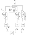
- FIG. 1 is an exemplary embodiment of a wireless network in accordance with the invention.
- FIG. 2 is an exemplary embodiment of a wireless network switch of FIG. 1 .
- FIG. 3A is an exemplary embodiment of the wireless network switch operating in cooperation with an Access Point (AP) to respond to a security attack on a wireless station (STA) of the wireless network.
- AP Access Point
- STA wireless station
- FIG. 3B is an exemplary embodiment of the operations of station management logic for a wireless network switch to block communications by a station under a security attack.
- FIG. 4 is an exemplary embodiment of a method of operation of the wireless network switch responding to a security attack.
- FIG. 5 is an exemplary embodiment of the wireless network switch operating in cooperation with a wireless station (STA) for centralized load balancing for the wireless network.
- STA wireless station
- FIG. 6 is an exemplary embodiment of a method of operation of the wireless network switch for load balancing.
- FIG. 7 is an exemplary embodiment of a wireless network switch operating in cooperation with an Access Point (AP) to detect coverage holes over a site.
- AP Access Point
- FIG. 8 is an exemplary embodiment of a method of operation of the wireless network switch for detecting coverage holes.
- FIG. 9 is an exemplary embodiment of a method of operation of the wireless network switch for limiting broadcast and/or multicast traffic over an Access Point (AP).
- AP Access Point
- FIG. 10 is an exemplary embodiment of a method of operation of the wireless network switch for RF neighborhood detection.
- Embodiments of the invention relate to a centralized mechanism for managing operations of and communications within a wireless network.
- the centralized mechanism may be deployed as station management logic (STM) within a wireless network switch.
- This logic may be deployed as a software module, executed by a processor, that is configured to handle the processing of a plurality of management messages during an Association phase between a STA and an AP, including but not limited or restricted to one or more of the following: PROBE REQUEST, PROBE RESPONSE, AUTHENTICATION, DEAUTHENTICATION, ASSOCIATION REQUEST, ASSOCIATION RESPONSE, REASSOCIATION REQUEST, REASSOCIATION RESPONSE and DISASSOCATION.
- the station management logic (STM) is configured to provide security protection, load balancing, coverage hole detection, and broadcast/multicast traffic reduction.
- the invention may be applicable to a variety of wireless networks such as a wireless local area network (WLAN) or wireless personal area network (WPAN).
- WLAN wireless local area network
- WPAN wireless personal area network
- the wireless network may be configured in accordance with any wireless communication protocol.
- Examples of various types of wireless communication protocols include Institute of Electrical and Electronics Engineers (IEEE) 802.11 standards, High Performance Radio Local Area Networks (HiperLAN) standards, WiMax (IEEE 802.16) and the like.
- the IEEE 802.11 standard may an IEEE 802.11b standard entitled “Wireless LAN Medium Access Control (MAC) and Physical Layer (PHY) specifications: Higher-Speed Physical Layer Extension in the 2.4 GHz Band” (IEEE 802.11b, 1999); an IEEE 802.11a standard entitled “Wireless LAN Medium Access Control (MAC) and Physical Layer (PHY) specifications: High-Speed Physical Layer in the 5 GHz Band” (IEEE 802.11a, 1999); a revised IEEE 802.11 standard “Wireless LAN Medium Access Control (MAC) and Physical Layer (PHY) specifications” (IEEE 802.11, 1999); or an IEEE 802.11g standard entitled “Wireless LAN Medium Access Control (MAC) and Physical Layer (PHY) specifications: Further Higher Data Rate Extension in the 2.4 GHz Band” (IEEE 802.11g, 2003).
- IEEE 802.11b entitled “Wireless LAN Medium Access Control (MAC) and Physical Layer (PHY) specifications: Higher-Speed Physical Layer Extension in the 2.4 GHz Band”
- IEEE 802.11a entitled “Wir
- logic includes hardware and/or software module(s) that are configured to perform one or more functions.
- a “processor” is logic that processes information. Examples of a processor include a microprocessor, an application specific integrated circuit, a digital signal processor, a micro-controller, a finite state machine, or even combinatorial logic.
- a “software module” is executable code such as an operating system, an application, an applet or even a routine.
- Software modules may be stored in any type of memory, namely suitable storage medium such as a programmable electronic circuit, a semiconductor memory device, a volatile memory (e.g., random access memory, etc.), a non-volatile memory (e.g., read-only memory, flash memory, etc.), a floppy diskette, an optical disk (e.g., compact disk or digital versatile disc “DVD”), a hard drive disk, tape, or any kind of interconnect (defined below).
- suitable storage medium such as a programmable electronic circuit, a semiconductor memory device, a volatile memory (e.g., random access memory, etc.), a non-volatile memory (e.g., read-only memory, flash memory, etc.), a floppy diskette, an optical disk (e.g., compact disk or digital versatile disc “DVD”), a hard drive disk, tape, or any kind of interconnect
- interconnect is generally defined as an information-carrying medium that establishes a communication pathway.
- the interconnect may be a wired interconnect, where the medium is a physical medium (e.g., electrical wire, optical fiber, cable, bus traces, etc.) or a wireless interconnect (e.g., air in combination with wireless signaling technology).
- Information is defined as data, address, control or any combination thereof.
- information may be transmitted as a message, namely a collection of bits in a predetermined format.
- One particular type of message is a frame including a header and a payload, each having a predetermined number of bits of information.
- wireless network 100 having a centralized mechanism to manage the operations of and communications within wireless network 100 is illustrated.
- wireless network 100 is deployed as a wireless local area network (WLAN) that comprises one or more wireless network switches 110 (e.g., WLAN switch) in communication with one or more access points (APs) 130 1 - 130 N (where N ⁇ 1) over an interconnect 120 .
- Interconnect 120 may be a wired or wireless information-carrying medium or even a mesh network for example.
- STAs wireless stations
- M ⁇ 1 wireless stations
- WLAN switch 110 comprises logic 200 that supports communications with APs 130 1 - 130 N over interconnect 120 .
- the wired network features resources that are available for users of wireless network 100 .
- resources may include database or data storage servers.
- WLAN switch 110 supports bi-directional communications by receiving messages from and transmitting messages to one or more targeted APs 130 1 , . . . , 130 N over interconnect 120 .
- Interconnect 120 may be part of any type of private or public wired network, including but not limited or restricted to Ethernet, Token Ring, Asynchronous Transfer Mode (ATM), Internet or the like.
- the network communication protocol utilized over interconnect 120 may be selected from a variety of protocols, including TCP/IP.
- logic 200 of WLAN switch 110 comprises station management logic (STM) 210 and a wired or wireless connector 220 .
- Connector 220 enables an exchange of information between a wired network and station management logic 210 .
- connector 220 may provide coupling for a plurality of Ethernet interconnects, serial interconnects and the like to enable access with APs over a wired public or private network.
- station management logic 210 processes information extracted from the wireless message.
- station management logic 210 is implemented as a processor executing a program, stored in memory, that is configured to provide centralized management involving security protection, load balancing, coverage hole detection, and broadcast/multicast traffic reduction of wireless network 100 .
- station management logic 210 may be a state machine. Regardless of the chosen architectural implementation, in order to provide such centralized management, different information is received, extracted and processed as described below.
- each AP 130 1 , . . . , or 130 N supports bi-directional communications by receiving wireless messages from any or all of the STAs 140 1 - 140 M in its coverage area and transferring data from the messages over interconnect 120 to which WLAN switch 110 is coupled.
- STA 140 1 is adapted to communicate with and accesses information from any associated AP.
- STA 140 1 is associated with AP 130 1 and communicates over the air in accordance with a selected wireless communications protocol.
- AP 130 1 generally operates as a transparent bridge connecting both wireless network 100 featuring STA 140 1 with the wired network.
- STA 140 1 comprises a removable, wireless network interface card (NIC) that is separate from or employed within a wireless device that processes information (e.g., computer, personal digital assistant “PDA”, telephone, alphanumeric pager, etc.).
- NIC wireless network interface card
- the NIC comprises a wireless transceiver, although it is contemplated that the NIC may feature only receive (RX) or transmit (TX) functionality such that only a receiver or transmitter is implemented.
- a wireless network switch e.g., WLAN switch 110
- one or more access points e.g., AP 130 1
- STA 140 1 a wireless station
- One common security attack is a “man-in-the-middle” attack that involves an attacker assuming the identity of an AP or STA and sending DEAUTHENTICATION messages to the other. This disrupts communications between AP 130 1 and STA 140 1 so that the attacker can monitor (“sniff”) for passwords and other information as communication is reestablished.
- STA 140 1 receives a DEAUTHENTICATION message 300 that impersonates origination from AP 130 1 . However, since STA 140 1 is in the coverage area for AP 130 1 , AP 130 1 detects DEAUTHENTICATION message 300 and forwarded the same to WLAN switch 110 for processing. Upon analysis of the type and subtype fields 310 of DEAUTHENTICATION message 300 , WLAN switch 110 is able to determine that a DEAUTHENTICATION message has been received.
- WLAN switch 110 is responsible for generating all valid DEAUTHENTICATION messages to STAs.
- station management software executed within WLAN switch 110 is able to immediately determine whether DEAUTHENTICATION message 300 is invalid through analysis of a source address (SRC_ADDR) 320 and/or destination address (DEST_ADDR) 330 .
- DEST_ADDR 330 indicates that the STA 140 1 is the targeted device, but WLAN switch 110 has no record of generating DEAUTHENTICATION message 300 , DEAUTHENTICATION message 300 is deemed invalid. Namely, DEST_ADDR 330 of DEAUTHENTICATION message 300 is compared to corresponding information from all valid DEAUTHENICATION messages recently transmitted from WLAN switch 110 . Data associated with recent, valid DEAUTHENTICATION messages are stored within a table accessible by WLAN switch 110 . If no match is detected, DEAUTHENTICATION message 300 is invalid. This causes WLAN switch 110 to block communications generated by STA 140 1 for associating with any AP 130 1 , . . . or 130 N .
- WLAN switch 110 places the MAC address of STA 140 1 into a security table 340 . Thereafter, WLAN switch 110 sends a message to an AP (e.g., AP 130 2 ), to which STA 140 1 is currently associated, to disassociate itself from STA 140 1 . Thereafter, upon receipt of any PROBE REQUEST, ASSOCIATION REQUEST or REASSOCIATION REQUEST messages transferred any AP 130 1 , . . . or 130 N in wireless network 100 , WLAN switch 110 accesses security table 340 to determine whether the station initiating the request message, such as STA 140 1 , is blocked. This may be accomplished by comparison of the SRC_ADDR of the request message to contents of security table 340 as shown.
- AP e.g., AP 130 2
- STA 140 1 may be precluded from freely communicating with any APs 130 1 - 130 N of wireless network 100 for either (i) a prescribed time period, which may be static or programmable for each network, or (ii) an indefinite duration until the network administrator removes STA 140 1 from security table 340 .
- an AP monitors the airwaves within its coverage area for broadcast, multicast and addressed wireless messages (item 400 ). For each received wireless message, the AP determines the particular type of wireless message received (item 410 ). This is accomplished by analyzing a message (or frame) type field in the header of the message. Upon determining a detected wireless message is a management message, such as a DEAUTHENTICATION message for example, the AP forwards the DEAUTHENTICATION message to the station management logic of the wireless network switch (items 420 and 425 ).
- a management message such as a DEAUTHENTICATION message for example
- the station management logic During normal operations, the station management logic generates all valid DEAUTHENTICATION messages to STAs. Upon receipt of the DEAUTHENTICATION message, which has been generated by a device other than the wireless network switch, the station management logic knows that a targeted STA is being attacked by reviewing of the DEST_ADDR of DEAUTHENTICATION message with records of recently generated DEAUTHENTICATION messages for example (item 430 ). This causes the station management logic to continuously block requests made by the targeted STA (item 440 ). These requests include a PROBE REQUEST, an ASSOCIATION REQUEST, a REASSOCIATION REQUEST and the like.
- requests from the targeted STA are blocked by the station management logic monitoring for management messages from the targeted STA (e.g., analyzing source address of a PROBE REQUEST, ASSOCIATION REQUEST, or REASSOCIATION REQUEST).
- station management logic Upon discovery, station management logic generates a message to the AP to deny such request.
- the targeted STA is permitted by the station management logic to freely associate with any AP (blocks 450 and 460 ). Such blocking may be lifted by the station management logic if (1) the network administrator manually clears the targeted STA from a block list, or (2) a prescribed time period for blocking requests by STA has elapsed. The prescribed time may automatically elapse if based on a policy rule established by the network administrator.
- wireless network switch 110 operating in cooperation with one or more access points (e.g., AP 130 1 , AP 130 2 , AP 130 3 ) and a wireless station (STA 140 1 ) attempting to associate with one of the APs 130 1 - 130 3 is shown.
- station management logic 210 of wireless network switch 110 provides centralized control in steering STA 140 1 to a suitable AP during the Association phase.
- STA 140 1 is configured to associate with an AP through passive scanning (beacons) or active scanning. “Active scanning” involves STA 140 1 broadcasting a PROBE REQUEST message 500 to all APs capable of receiving the request on multiple channels. For this embodiment, APs 130 1 - 130 3 receive a first PROBE REQUEST message 500 . However, instead of each AP 130 1 - 130 3 returning a response to STA 140 1 , first PROBE REQUEST message 500 is altered and subsequently routed to station management logic 210 .
- each AP 130 1 - 130 3 measures the received signal strength for first PROBE REQUEST message 500 and generates a corresponding received signal strength indicator (RSSI) value 510 1 - 510 3 .
- RSSI received signal strength indicator
- the RSSI value 510 1 - 510 3 is loaded into a field 520 of first PROBE REQUEST 500 (e.g., Duration ID field) to produce modified Probe Requests 530 1 - 530 3 , respectively.
- modified Probe Request messages 530 1 - 530 3 are transferred to station management logic 210 from AP 130 1 - 130 3 , respectively.
- station management logic (STM) 210 does not respond to modified Probe Request messages 530 1 - 530 3 , but rather awaits a second set of Probe Request messages 550 1 - 550 3 or modified versions thereof.
- Probe Request messages 550 1 - 550 3 may be modified to include the newly measured RSSI value. However, if the time duration between first PROBE REQUEST 500 and second PROBE REQUEST message 540 is nominal (e.g., a few milliseconds), modified Probe Request messages 550 1 - 550 3 need not include an updated RSSI value.
- additional parameters such as (i) number of users on AP 130 1 - 130 3 or (ii) percentage of bandwidth utilization by AP 130 1 - 130 3 for example, may be monitored by the AP themselves and periodically transferred to wireless network switch 110 .
- the values of these parameters may be contained in fields of the first or second set of modified Probe Request messages 530 1 - 530 3 or 550 1 - 550 3 , respectively.
- the number of users on AP 130 1 - 130 3 and/or the percentage of bandwidth utilization by AP 130 1 - 130 3 may be monitored by wireless network switch 110 internally, where load balancing is activated when maximum or minimum thresholds are exceeded.
- STM 210 analyzes the RSSI values and/or load on each AP, and responds to second PROBE REQUEST message 540 on behalf of the AP 130 1 , . . . , or 130 3 selected to associate with STA 140 , (e.g., AP 130 1 ).
- This allows STM 210 to steer STA 140 1 to a suitable AP based on instantaneous load and proximity.
- this centralized Request/Response processing allows overloaded APs and/or APs remotely located from the STA to be hidden during the Association phase.
- STA 140 1 After PROBE RESPONSE message 560 has been received, STA 140 1 starts the authentication and associate exchanges with the selected AP 130 1 . Thereafter, communications are established between STA 140 1 and AP 130 1 .
- FIG. 6 is an exemplary embodiment of a method of operation of the wireless network switch for load balancing during an initial communication session.
- STA sends a PROBE REQUEST message in an attempt to associate with an AP (item 600 ).
- the PROBE REQUEST message is usually sent to a broadcast address so that multiple APs can receive the PROBE REQUEST message.
- each AP computes the RSSI value for the received PROBE REQUEST message (item 610 ).
- the RSSI value may be placed in an unused field of the PROBE REQUEST message for transfer to the STM (item 620 ).
- each AP may be configured to send a message other than a modified PROBE REQUEST message.
- This message would be inclusive of the RSSI value and only selected information from the received PROBE REQUEST message.
- the selected information may include (i) a code to identify that the message is a PROBE REQUEST message, (ii) an address of the STA generating the PROBE REQUEST message, (iii) load of the AP, etc.
- the STM Upon receipt of messages from the APs, generated in response to receipt of the PROBE REQUEST, the STM does not respond, but rather awaits a second set of messages produced in response to another (second) PROBE REQUEST message generated by the STA when the previous (first) PROBE REQUEST message was not responded to (items 650 and 660 ).
- the second set of messages may be modified PROBE REQUEST messages including newly measured RSSI value and/or load information).
- the second set of messages may be identical to the subsequent (second) PROBE REQUEST message or may be modified to include other information needed to determine the optimal AP to associate with the STA.
- the STM After receipt of the second set of messages, the STM analyzes the RSSI values and/or load on each AP, and responds to second PROBE REQUEST message on behalf of the AP selected to associate with STA (items 670 , 680 and 690 ).
- the station management logic hiding overloaded APs and/or APs remotely located from the STA during the Association phase, the overall wireless traffic is substantially reduced.
- a “coverage hole” is a location where a STA cannot associate with any AP.
- Centralized station management logic allows for the wireless network to discover coverage holes and to automatically perform events to eliminate or substantially reduce discovered coverage holes. Examples of such events include, but are not limited or restricted to (1) increasing transmission power for selected APs or (2) notifying a network administrator regarding the coverage hole.
- wireless network 100 comprises wireless network switch 110 , one or more access points (e.g., AP 130 1 , . . . , AP 130 N ) and one or more wireless stations (e.g., STA 140 1 ).
- Station management logic (STM) 210 implemented within wireless network switch 110 , provides centralized control for management messages received from each AP 130 1 - 130 N during an Association phase with STA 140 1 .
- each AP 130 1 - 130 N measures the RSSI value for a received management frame 700 and provides the RSSI value to STM 210 .
- two RSSI thresholds are used to determine the presence of a coverage hole. These thresholds may be static in nature (e.g., set in one-time programmable memory of wireless network switch 110 ) or may be dynamic in nature (e.g., set by a network administrator in memory of wireless network switch 110 ).
- a first RSSI threshold (referred to as “Good_RSSI_Threshold”) indicates that STA 140 1 is not in a coverage hole if any AP 130 1 , . . . , or 130 N detects an RSSI value more than Good_RSSI_Threshold for any message from STA 140 1 .
- a second RSSI threshold (referred to as “Bad_RSSI_Threshold”) indicates that that STA 140 1 may be in a coverage hole if all APs 130 1 - 130 N detect an RSSI value below Bad_RSSI_Threshold during message broadcasts from STA 140 1 during the Association phase.
- Good_RSSI_Threshold may be set to approximately 20 dbm0 while Bad_RSSI_Threshold may be set to approximately 10 dbm0.
- STA 140 1 wireless communications by STA 140 1 are monitored. If none of APs 130 1 - 130 N detects an RSSI value for a management message above Bad_RSSI_Threshold, STM 210 adds STA 140 1 to a potential coverage hole list. Thereafter, if STA 140 1 either fails to complete association with an AP or consistently provides messages with RSSI values below Bad_RSSI_Threshold to the associated AP, STA 140 1 is determined to be in a coverage hole. Namely, the placement of STA 140 1 within an entry of the potential coverage hole list causes STM 210 to perform events to mitigate or eliminate the potential coverage hole.
- STM 210 Upon receiving a management frame, which originates from STA 140 1 and indicates an RSSI value above Good_RSSI_Threshold, STM 210 removes STA 140 1 from an entry of the potential coverage hole list.
- a plurality of RSSI thresholds are established (item 800 ). These “thresholds,” namely Good_RSSI_Threshold and Bad_RSSI_Threshold, are used to determine the presence of a coverage hole.
- each AP measures the RSSI value for the management frame and provides the RSSI value to the station management logic “STM” (items 810 , 820 and 830 ).
- the STM determines whether any of these RSSI values are greater than Good_RSSI_Threshold (item 840 ). If so, there is no coverage hole at the location of the monitored STA (item 850 ).
- station management logic (STM) 210 has knowledge of all STAs 140 1 - 140 M associated with all APs 130 1 - 130 N in wireless network 100 . Namely, STM 210 maintains an AP-STA table 900 to identify which STAs are associated with which APs.
- AP-STA table 900 comprises MAC addresses 910 for APs 130 1 - 130 N and MAC addresses 920 of STAs 140 i , . . . , and/or 140 j associated with each AP 130 1 , . . . , or 130 N .
- AP-STA table 900 is updated.
- the MAC address for the newly associated STA is added to AP-STA table 900 after the Association phase has completed.
- a newly disassociated STA is removed from AP-STA table 900 .
- STM 210 determines whether an AP (e.g., AP 130 2 ) now has no STAs associated therewith. If so, STM 210 removes the MAC address of AP 130 2 from a multicast group list 930 stored within wireless network switch 110 . Since multicast group list 930 is accessed by wireless network switch 110 to determine the targeted destinations for multicast and broadcast transmissions, AP 130 2 would discontinue sending any broadcast or multicast messages until at least one STA becomes associated with AP 130 2 . Once a STA becomes associated with AP 130 2 , STM 210 adds the MAC address of AP 130 2 back to multicast group list 930 .
- AP e.g., AP 130 2
- a wireless network switch receives PROBE REQUEST messages on different channels through different APs ( 1000 ). These PROBE REQUEST messages originate from the same STA.
- the wireless network switch Upon receipt, the wireless network switch dynamically computes RF neighborhoods of all APs deployed ( 1010 ). According to one embodiment of the invention, a channel number and a MAC address associated with the AP is included as information within the PROBE REQUEST message ( 1020 ). The wireless network switch creates a filtered channel list, which includes the MAC address of the AP and channel number extracted from PROBE REQUEST messages ( 1030 ). The filtered channel list is provided to the STA at completion of its association, such as in an ASSOCIATION RESPONSE message for example ( 1040 ). This enables the STA to use this filtered channel list to make more efficient mobility decision in future associations.
Abstract
Description
Claims (16)
Priority Applications (5)
| Application Number | Priority Date | Filing Date | Title |
|---|---|---|---|
| US10/806,601 US7969937B2 (en) | 2004-03-23 | 2004-03-23 | System and method for centralized station management |
| US13/168,789 US8750272B2 (en) | 2004-03-23 | 2011-06-24 | System and method for centralized station management |
| US13/363,309 US9432848B2 (en) | 2004-03-23 | 2012-01-31 | Band steering for multi-band wireless clients |
| US13/460,795 US20120218931A1 (en) | 2004-03-23 | 2012-04-30 | System and Method for Centralized Station Management |
| US13/460,813 US9019911B2 (en) | 2004-03-23 | 2012-04-30 | System and method for centralized station management |
Applications Claiming Priority (1)
| Application Number | Priority Date | Filing Date | Title |
|---|---|---|---|
| US10/806,601 US7969937B2 (en) | 2004-03-23 | 2004-03-23 | System and method for centralized station management |
Related Parent Applications (1)
| Application Number | Title | Priority Date | Filing Date |
|---|---|---|---|
| US13/156,215 Continuation-In-Part US8699418B2 (en) | 2004-03-23 | 2011-06-08 | Band steering for multi-band wireless clients |
Related Child Applications (1)
| Application Number | Title | Priority Date | Filing Date |
|---|---|---|---|
| US13/168,789 Division US8750272B2 (en) | 2004-03-23 | 2011-06-24 | System and method for centralized station management |
Publications (2)
| Publication Number | Publication Date |
|---|---|
| US20050213579A1 US20050213579A1 (en) | 2005-09-29 |
| US7969937B2 true US7969937B2 (en) | 2011-06-28 |
Family
ID=34989736
Family Applications (4)
| Application Number | Title | Priority Date | Filing Date |
|---|---|---|---|
| US10/806,601 Active 2028-05-17 US7969937B2 (en) | 2004-03-23 | 2004-03-23 | System and method for centralized station management |
| US13/168,789 Active 2024-11-28 US8750272B2 (en) | 2004-03-23 | 2011-06-24 | System and method for centralized station management |
| US13/460,795 Abandoned US20120218931A1 (en) | 2004-03-23 | 2012-04-30 | System and Method for Centralized Station Management |
| US13/460,813 Expired - Lifetime US9019911B2 (en) | 2004-03-23 | 2012-04-30 | System and method for centralized station management |
Family Applications After (3)
| Application Number | Title | Priority Date | Filing Date |
|---|---|---|---|
| US13/168,789 Active 2024-11-28 US8750272B2 (en) | 2004-03-23 | 2011-06-24 | System and method for centralized station management |
| US13/460,795 Abandoned US20120218931A1 (en) | 2004-03-23 | 2012-04-30 | System and Method for Centralized Station Management |
| US13/460,813 Expired - Lifetime US9019911B2 (en) | 2004-03-23 | 2012-04-30 | System and method for centralized station management |
Country Status (1)
| Country | Link |
|---|---|
| US (4) | US7969937B2 (en) |
Cited By (7)
| Publication number | Priority date | Publication date | Assignee | Title |
|---|---|---|---|---|
| US20100027459A1 (en) * | 2008-07-31 | 2010-02-04 | Canon Kabushiki Kaisha | Communication system and method for controlling the same |
| US8072952B2 (en) * | 2006-10-16 | 2011-12-06 | Juniper Networks, Inc. | Load balancing |
| US20120004001A1 (en) * | 2010-06-30 | 2012-01-05 | Fujitsu Limited | Coverage hole compensation in wireless communication networks |
| US20120051244A1 (en) * | 2010-08-24 | 2012-03-01 | Sony Corporation | Wireless communication apparatus, program, wireless communication method, and wireless communication system |
| US8750272B2 (en) | 2004-03-23 | 2014-06-10 | Aruba Networks, Inc. | System and method for centralized station management |
| US9432848B2 (en) | 2004-03-23 | 2016-08-30 | Aruba Networks, Inc. | Band steering for multi-band wireless clients |
| US20170150533A1 (en) * | 2015-11-19 | 2017-05-25 | Nike, Inc. | System, apparatus, and method for received signal strength indicator (rssi) based authentication |
Families Citing this family (36)
| Publication number | Priority date | Publication date | Assignee | Title |
|---|---|---|---|---|
| US20090252097A1 (en) * | 2008-04-08 | 2009-10-08 | Aruba Networks, Inc. | Band steering for multi-band wireless clients |
| US8699418B2 (en) * | 2008-04-08 | 2014-04-15 | Aruba Networks, Inc. | Band steering for multi-band wireless clients |
| US20060045113A1 (en) * | 2004-08-31 | 2006-03-02 | Palisca Andrea G | Method for establishing high-reliability wireless connectivity to mobile devices using multi channel radios |
| US7480264B1 (en) * | 2005-02-10 | 2009-01-20 | Sonicwall, Inc. | Centralized wireless LAN load balancing |
| US8139521B2 (en) * | 2005-10-28 | 2012-03-20 | Interdigital Technology Corporation | Wireless nodes with active authentication and associated methods |
| CN101379769B (en) * | 2006-02-01 | 2011-07-13 | Lg电子株式会社 | Method for transmitting information in wireless local area network system |
| US7499718B2 (en) | 2006-08-01 | 2009-03-03 | Cisco Technology, Inc. | Enhanced coverage hole detection in wireless networks |
| US7826838B1 (en) * | 2006-11-02 | 2010-11-02 | Nvidia Corporation | Adaptive contention for wireless devices |
| US9088907B2 (en) * | 2007-06-18 | 2015-07-21 | Xirrus, Inc. | Node fault identification in wireless LAN access points |
| US8625538B2 (en) * | 2007-11-13 | 2014-01-07 | International Business Machines Corporation | Method and apparatus for association control in mobile wireless networks |
| TWI372531B (en) * | 2008-06-10 | 2012-09-11 | Ind Tech Res Inst | Wireless network, access point, and load balancing method thereof |
| US8204029B2 (en) * | 2008-11-10 | 2012-06-19 | Cisco Technology, Inc. | Mobile intelligent roaming using multi-modal access point devices |
| TW201108793A (en) * | 2009-08-31 | 2011-03-01 | Ralink Technology Corp | Method and apparatus for roaming seamlessly |
| US8848590B2 (en) * | 2009-09-24 | 2014-09-30 | Nokia Corporation | Multicast group management in wireless networks |
| US9130834B2 (en) * | 2009-12-22 | 2015-09-08 | Nokia Solutions And Networks Oy | Method and device for monitoring backbone inter base-station communication |
| CN102131235A (en) * | 2010-01-15 | 2011-07-20 | 西门子公司 | Load balancing method in radio communication system |
| US10034300B2 (en) * | 2010-06-10 | 2018-07-24 | Cisco Technology, Inc | Load based probe response scheduling |
| US8687512B2 (en) * | 2011-04-29 | 2014-04-01 | Aruba Networks, Inc. | Signal strength aware band steering |
| US9578663B2 (en) * | 2011-12-08 | 2017-02-21 | Lg Electronics Inc. | Method and apparatus for setting up link at high-speed in wireless communication system |
| WO2013111309A1 (en) * | 2012-01-26 | 2013-08-01 | 富士通株式会社 | Communication method, communication terminal and base station apparatus |
| US9419858B2 (en) | 2012-07-23 | 2016-08-16 | Maxlinear, Inc. | Method and system for service group management in a cable network |
| US8761142B2 (en) * | 2012-10-19 | 2014-06-24 | Ubiquiti Networks, Inc. | Distributed seamless roaming in wireless networks |
| US9137724B1 (en) * | 2012-12-21 | 2015-09-15 | Juniper Networks, Inc. | Methods and apparatus for load balancing in high density depolyments of wireless access points according to spatial stream capabilities |
| EP2785136B1 (en) * | 2013-03-27 | 2016-06-15 | Fujitsu Limited | Relieving Congestion in Wireless Local Area Networks |
| US9401874B2 (en) * | 2013-08-14 | 2016-07-26 | Qualcomm Incorporated | Minimizing coverage holes in a communication network |
| US10257775B2 (en) * | 2013-08-28 | 2019-04-09 | Telefonaktiebolaget Lm Ericsson (Publ) | Attachment of a mobile terminal to a radio access network |
| US9655037B2 (en) * | 2014-04-07 | 2017-05-16 | Qualcomm Incorporated | Method and apparatus for an improved mechanism for selecting an access point |
| US9867117B2 (en) * | 2014-07-25 | 2018-01-09 | Comcast Cable Communications, Llc | Network admission control |
| JP6267603B2 (en) * | 2014-08-27 | 2018-01-24 | 日本電信電話株式会社 | COMMUNICATION CONTROL SYSTEM, COMMUNICATION CONTROL DEVICE, AND COMMUNICATION CONTROL METHOD |
| US9913193B2 (en) * | 2015-02-20 | 2018-03-06 | Qualcomm Incorporated | Access point steering |
| US9973935B2 (en) | 2015-07-24 | 2018-05-15 | Parallel Wireless, Inc. | SON-controlled DFS |
| CN107404752A (en) * | 2017-07-21 | 2017-11-28 | 深圳市盛路物联通讯技术有限公司 | Frequency choosing method and internet-of-things terminal based on signal intensity |
| EP3689034B1 (en) * | 2017-09-30 | 2022-09-28 | ARRIS Enterprises LLC | Access-point discovery of wireless-network topology |
| US11211998B2 (en) * | 2019-04-03 | 2021-12-28 | Baylor University | Virtual wireless network |
| US20210111990A1 (en) * | 2019-10-14 | 2021-04-15 | Cisco Technology, Inc. | Systems and methods for providing multiple disjointed paths to core network at first-mile access |
| US11576048B1 (en) * | 2020-04-28 | 2023-02-07 | T-Mobile Innovations Llc | Mitigating authentication-based hacking of access restricted telecommunication services |
Citations (58)
| Publication number | Priority date | Publication date | Assignee | Title |
|---|---|---|---|---|
| US5193101A (en) * | 1991-02-04 | 1993-03-09 | Motorola, Inc. | On-site system frequency sharing with trunking systems using spread spectrum |
| US5212806A (en) * | 1990-10-29 | 1993-05-18 | International Business Machines Corporation | Distributed control methods for management of migrating data stations in a wireless communications network |
| US5428816A (en) * | 1993-09-09 | 1995-06-27 | Hughes Aircraft Company | Method and apparatus for mobile assisted handoff |
| US5509051A (en) * | 1993-09-09 | 1996-04-16 | Hughes Aircraft Company | Prioritization of neighboring cells |
| US5640677A (en) * | 1993-07-09 | 1997-06-17 | Telefonaktiebolaget Lm Ericsson | Best server selection in layered cellular radio system |
| US5673307A (en) * | 1994-02-17 | 1997-09-30 | Spectralink Corporation | Handoff method for indoor cellular phone system |
| US5878119A (en) * | 1996-06-20 | 1999-03-02 | Northern Telecom Limited | Idle suppression and signal threshold determination therefor |
| US5878328A (en) * | 1995-12-21 | 1999-03-02 | At&T Wireless Services, Inc. | Method and apparatus for wireless communication system organization |
| US5991287A (en) * | 1996-12-30 | 1999-11-23 | Lucent Technologies, Inc. | System and method for providing seamless handover in a wireless computer network |
| US6038444A (en) * | 1994-08-19 | 2000-03-14 | Trimble Navigation Limited | Method and apparatus for advising cellphone users of possible actions to avoid dropped calls |
| US20010018346A1 (en) * | 1999-12-28 | 2001-08-30 | Ntt Docomo, Inc. | Method and apparatus for stabilizing communication in mobile communication system |
| US20020159544A1 (en) * | 2001-02-28 | 2002-10-31 | Jeyhan Karaoguz | Multi-mode quadrature amplitude modulation receiver for high rate wireless personal area networks |
| US20020181418A1 (en) * | 2001-05-08 | 2002-12-05 | Awater Geert Arnout | Network system comprising access points |
| US6560442B1 (en) * | 1999-08-12 | 2003-05-06 | Ericsson Inc. | System and method for profiling the location of mobile radio traffic in a wireless communications network |
| US6697337B1 (en) * | 2001-09-17 | 2004-02-24 | Networks Associates Technology, Inc. | Method and apparatus for capture, analysis and display of packet information sent in an IEEE 802.11 wireless network |
| US20040037247A1 (en) * | 2002-08-23 | 2004-02-26 | Koninklijke Philips Electronics N.V. | Frequency hopping in 5GHz WLAN via dynamic frequency selection |
| US20040039817A1 (en) * | 2002-08-26 | 2004-02-26 | Lee Mai Tranh | Enhanced algorithm for initial AP selection and roaming |
| US20040042609A1 (en) * | 2002-09-04 | 2004-03-04 | Tekelec | Methods and systems for enhancing network security in a telecommunications signaling network |
| US20040063455A1 (en) * | 2002-08-07 | 2004-04-01 | Extricom Ltd. | Wireless LAN with central management of access points |
| US20040063427A1 (en) * | 2002-09-30 | 2004-04-01 | Murali Narasimha | Greyzone system selection |
| US20040068668A1 (en) * | 2002-10-08 | 2004-04-08 | Broadcom Corporation | Enterprise wireless local area network switching system |
| US20040185852A1 (en) * | 2003-03-08 | 2004-09-23 | Samsung Electronics Co., Ltd. | System and method for implementing a handoff in a traffic state in a broadband wireless access communication system |
| US20040243846A1 (en) * | 2003-05-30 | 2004-12-02 | Aboba Bernard D. | Secure association and management frame verification |
| US20050003827A1 (en) * | 2003-02-13 | 2005-01-06 | Whelan Robert J. | Channel, coding and power management for wireless local area networks |
| US6842726B1 (en) * | 2001-06-05 | 2005-01-11 | At&T Wireless Services, Inc. | Method of determining RF coverage area in a point-to-multipoint transmission system |
| US20050059353A1 (en) * | 2003-09-11 | 2005-03-17 | Smith Brian K. | Method and system for providing adaptive probe requests |
| US20050068925A1 (en) * | 2002-07-26 | 2005-03-31 | Stephen Palm | Wireless access point setup and management within wireless local area network |
| US20050070275A1 (en) * | 2003-09-30 | 2005-03-31 | Intel Corporation | Wireless network roaming timer method and apparatus |
| US20050075142A1 (en) * | 2003-06-19 | 2005-04-07 | Ipr Licensing, Inc. | Antenna steering and hidden node recognition for an access point |
| US20050086465A1 (en) * | 2003-10-16 | 2005-04-21 | Cisco Technology, Inc. | System and method for protecting network management frames |
| US20050083210A1 (en) * | 2002-06-27 | 2005-04-21 | Shuey Kenneth C. | Dynamic self-configuring metering network |
| US20050090259A1 (en) * | 2003-10-24 | 2005-04-28 | Qualcomm Incorporated | Handoff between a wireless local area network and a cellular communication system |
| US20050119001A1 (en) * | 2003-11-28 | 2005-06-02 | Hitachi Communication Technologies, Ltd. | Wireless communication system, server and mobile station therefor |
| US20050128990A1 (en) * | 2003-12-12 | 2005-06-16 | Samsung Electronics Co., Ltd. | System and method for controlling operation states of a medium access control layer in a broadband wireless access communication system |
| US20050128988A1 (en) * | 2003-09-30 | 2005-06-16 | Simpson Floyd D. | Enhanced passive scanning |
| US20050138178A1 (en) * | 2003-12-19 | 2005-06-23 | Shaun Astarabadi | Wireless mobility manager |
| US20050135270A1 (en) * | 2003-12-19 | 2005-06-23 | Larsen James D. | Probing method for a multi-station network |
| US20050141498A1 (en) * | 2003-10-16 | 2005-06-30 | Cisco Technology, Inc | Network infrastructure validation of network management frames |
| US20050207448A1 (en) * | 2002-09-09 | 2005-09-22 | Iyer Pradeep J | Reconfigurable access point |
| US20050227623A1 (en) * | 2004-03-19 | 2005-10-13 | Micro-Star Int'l. Co., Ltd. | Wireless network service provider and associated channel-searching method |
| US20050245237A1 (en) * | 2001-09-28 | 2005-11-03 | Tomoko Adachi | Base station apparatus and terminal apparatus |
| US6973053B1 (en) * | 2000-09-12 | 2005-12-06 | Bbnt Solutions Llc | Using direct cluster member to cluster member links to improve performance in mobile communication systems |
| US20050277426A1 (en) * | 2002-07-31 | 2005-12-15 | Koninklijke Philips Electronics N.V. | System for locating a mobile unit |
| US7031336B2 (en) * | 2002-08-26 | 2006-04-18 | Colubris Networks, Inc. | Space-time-power scheduling for wireless networks |
| US20060111103A1 (en) * | 2003-04-29 | 2006-05-25 | Jeong Moo R | Fast active scanning wireless network apparatus and method |
| US20060116170A1 (en) * | 2002-05-24 | 2006-06-01 | Cisco Technology, Inc. | Intelligent association of nodes with PAN coordinator |
| US7079850B2 (en) * | 2002-04-11 | 2006-07-18 | Accenture Global Services Gmbh | Localization of radio-frequency transceivers |
| US20060200540A1 (en) * | 2003-09-04 | 2006-09-07 | Fujitsu Limited | Information provision method and computer-readable recording medium recording information provision program |
| US7113498B2 (en) * | 2002-06-05 | 2006-09-26 | Broadcom Corporation | Virtual switch |
| US7116980B2 (en) * | 2003-12-18 | 2006-10-03 | Crown Castle International Corp. | Method and system for management of radio frequency communication coverage over wide geographic areas |
| US20070025486A1 (en) * | 2002-10-01 | 2007-02-01 | Widefi, Inc. | Control message management in physical layer repeater |
| US20070165537A1 (en) * | 2003-12-17 | 2007-07-19 | Telefonaktiebolaget Lm Ericsson | System and method for radio resource management in a communication system |
| US7293088B2 (en) * | 2003-07-28 | 2007-11-06 | Cisco Technology, Inc. | Tag location, client location, and coverage hole location in a wireless network |
| US7301926B1 (en) * | 2003-04-04 | 2007-11-27 | Airespace, Inc. | Automatic coverage hole detection in computer network environments |
| US7313113B1 (en) * | 2003-04-04 | 2007-12-25 | Airespace, Inc. | Dynamic transmit power configuration system for wireless network environments |
| US20080031185A1 (en) * | 2002-01-11 | 2008-02-07 | Broadcom Corporation | Tracking multiple interface connections by mobile stations |
| US20080211641A1 (en) * | 2004-01-21 | 2008-09-04 | Numerex Corp. | Method and system for interacting with a vehicle over a mobile radiotelephone network |
| US7499718B2 (en) * | 2006-08-01 | 2009-03-03 | Cisco Technology, Inc. | Enhanced coverage hole detection in wireless networks |
Family Cites Families (28)
| Publication number | Priority date | Publication date | Assignee | Title |
|---|---|---|---|---|
| CA2137587C (en) | 1994-12-08 | 1999-03-23 | Murray Charles Baker | Broadcast/multicast filtering by the bridge-based access point |
| US6675208B1 (en) | 1997-10-14 | 2004-01-06 | Lucent Technologies Inc. | Registration scheme for network |
| US20030039232A1 (en) * | 2001-08-22 | 2003-02-27 | Alessio Casati | Method of sending a multicast message in such as a GPRS/UMTS network, and a mobile telecommunications network |
| US7330472B2 (en) | 2001-10-26 | 2008-02-12 | Sharp Laboratories Of America, Inc. | System and method for hybrid coordination in a wireless LAN |
| US7042865B1 (en) | 2001-11-16 | 2006-05-09 | Cisco Technology, Inc. | Automated IP multicast filtering |
| US7075904B1 (en) * | 2001-11-16 | 2006-07-11 | Sprint Spectrum L.P. | Method and system for multicasting messages to select mobile recipients |
| US7406319B2 (en) | 2001-11-19 | 2008-07-29 | At&T Corp. | WLAN having load balancing by access point admission/termination |
| CN100512546C (en) | 2001-12-05 | 2009-07-08 | 汤姆森许可公司 | Method and apparatus for calling a mobile terminal in a wireless LAN |
| US7016948B1 (en) * | 2001-12-21 | 2006-03-21 | Mcafee, Inc. | Method and apparatus for detailed protocol analysis of frames captured in an IEEE 802.11 (b) wireless LAN |
| US7689210B1 (en) | 2002-01-11 | 2010-03-30 | Broadcom Corporation | Plug-n-playable wireless communication system |
| US7689225B2 (en) | 2002-01-28 | 2010-03-30 | Ntt Docomo, Inc. | Method and apparatus for dormant mode support with paging |
| ES2400937T3 (en) | 2002-03-08 | 2013-04-15 | Telefonaktiebolaget Lm Ericsson (Publ) | Compatibility between several WLAN standards |
| US7424268B2 (en) * | 2002-04-22 | 2008-09-09 | Cisco Technology, Inc. | System and method for management of a shared frequency band |
| GB2387996B (en) | 2002-04-23 | 2006-01-11 | Lucent Technologies Inc | Wireless communication network with automatic threshold adjustment |
| US20040054774A1 (en) | 2002-05-04 | 2004-03-18 | Instant802 Networks Inc. | Using wireless network access points for monitoring radio spectrum traffic and interference |
| US6957067B1 (en) * | 2002-09-24 | 2005-10-18 | Aruba Networks | System and method for monitoring and enforcing policy within a wireless network |
| US20040102192A1 (en) | 2002-11-26 | 2004-05-27 | Texas Instruments Incorporated | Method and system for discovery and display of operating wireless networks |
| KR100580244B1 (en) | 2003-01-23 | 2006-05-16 | 삼성전자주식회사 | A handoff method in wirelessLAN |
| US6870815B2 (en) | 2003-01-30 | 2005-03-22 | Atheros Communications, Inc. | Methods for implementing a dynamic frequency selection (DFS) and a temporary channel selection feature for WLAN devices |
| US7453840B1 (en) * | 2003-06-30 | 2008-11-18 | Cisco Systems, Inc. | Containment of rogue systems in wireless network environments |
| US6980535B2 (en) | 2003-08-28 | 2005-12-27 | Motorola, Inc. | Passive probing for handover in a local area network |
| US20050085259A1 (en) | 2003-10-15 | 2005-04-21 | Conner W. S. | Technique to coordinate wireless network over a power line or other wired back channel |
| EP1557982B1 (en) | 2004-01-26 | 2011-05-11 | STMicroelectronics Srl | Method and system for admission control in communication networks |
| US7836189B2 (en) | 2004-01-26 | 2010-11-16 | Avaya Inc. | Multiple simultaneous wireless connections in a wireless local area network |
| US7170868B2 (en) | 2004-02-05 | 2007-01-30 | Motorola, Inc. | Method for preserving wireless resources in a wireless local area network |
| US7489648B2 (en) | 2004-03-11 | 2009-02-10 | Cisco Technology, Inc. | Optimizing 802.11 power-save for VLAN |
| US7969937B2 (en) | 2004-03-23 | 2011-06-28 | Aruba Networks, Inc. | System and method for centralized station management |
| US20080126455A1 (en) | 2006-07-11 | 2008-05-29 | France Telecom | Methods of protecting management frames exchanged between two wireless equipments, and of receiving and transmitting such frames, computer programs, and data media containing said computer programs |
-
2004
- 2004-03-23 US US10/806,601 patent/US7969937B2/en active Active
-
2011
- 2011-06-24 US US13/168,789 patent/US8750272B2/en active Active
-
2012
- 2012-04-30 US US13/460,795 patent/US20120218931A1/en not_active Abandoned
- 2012-04-30 US US13/460,813 patent/US9019911B2/en not_active Expired - Lifetime
Patent Citations (59)
| Publication number | Priority date | Publication date | Assignee | Title |
|---|---|---|---|---|
| US5212806A (en) * | 1990-10-29 | 1993-05-18 | International Business Machines Corporation | Distributed control methods for management of migrating data stations in a wireless communications network |
| US5193101A (en) * | 1991-02-04 | 1993-03-09 | Motorola, Inc. | On-site system frequency sharing with trunking systems using spread spectrum |
| US5640677A (en) * | 1993-07-09 | 1997-06-17 | Telefonaktiebolaget Lm Ericsson | Best server selection in layered cellular radio system |
| US5428816A (en) * | 1993-09-09 | 1995-06-27 | Hughes Aircraft Company | Method and apparatus for mobile assisted handoff |
| US5509051A (en) * | 1993-09-09 | 1996-04-16 | Hughes Aircraft Company | Prioritization of neighboring cells |
| US5673307A (en) * | 1994-02-17 | 1997-09-30 | Spectralink Corporation | Handoff method for indoor cellular phone system |
| US6038444A (en) * | 1994-08-19 | 2000-03-14 | Trimble Navigation Limited | Method and apparatus for advising cellphone users of possible actions to avoid dropped calls |
| US5878328A (en) * | 1995-12-21 | 1999-03-02 | At&T Wireless Services, Inc. | Method and apparatus for wireless communication system organization |
| US5878119A (en) * | 1996-06-20 | 1999-03-02 | Northern Telecom Limited | Idle suppression and signal threshold determination therefor |
| US5991287A (en) * | 1996-12-30 | 1999-11-23 | Lucent Technologies, Inc. | System and method for providing seamless handover in a wireless computer network |
| US6560442B1 (en) * | 1999-08-12 | 2003-05-06 | Ericsson Inc. | System and method for profiling the location of mobile radio traffic in a wireless communications network |
| US20010018346A1 (en) * | 1999-12-28 | 2001-08-30 | Ntt Docomo, Inc. | Method and apparatus for stabilizing communication in mobile communication system |
| US6973053B1 (en) * | 2000-09-12 | 2005-12-06 | Bbnt Solutions Llc | Using direct cluster member to cluster member links to improve performance in mobile communication systems |
| US20020159544A1 (en) * | 2001-02-28 | 2002-10-31 | Jeyhan Karaoguz | Multi-mode quadrature amplitude modulation receiver for high rate wireless personal area networks |
| US20020181418A1 (en) * | 2001-05-08 | 2002-12-05 | Awater Geert Arnout | Network system comprising access points |
| US6842726B1 (en) * | 2001-06-05 | 2005-01-11 | At&T Wireless Services, Inc. | Method of determining RF coverage area in a point-to-multipoint transmission system |
| US6697337B1 (en) * | 2001-09-17 | 2004-02-24 | Networks Associates Technology, Inc. | Method and apparatus for capture, analysis and display of packet information sent in an IEEE 802.11 wireless network |
| US20050245237A1 (en) * | 2001-09-28 | 2005-11-03 | Tomoko Adachi | Base station apparatus and terminal apparatus |
| US20080031185A1 (en) * | 2002-01-11 | 2008-02-07 | Broadcom Corporation | Tracking multiple interface connections by mobile stations |
| US7079850B2 (en) * | 2002-04-11 | 2006-07-18 | Accenture Global Services Gmbh | Localization of radio-frequency transceivers |
| US20060116170A1 (en) * | 2002-05-24 | 2006-06-01 | Cisco Technology, Inc. | Intelligent association of nodes with PAN coordinator |
| US7113498B2 (en) * | 2002-06-05 | 2006-09-26 | Broadcom Corporation | Virtual switch |
| US20050083210A1 (en) * | 2002-06-27 | 2005-04-21 | Shuey Kenneth C. | Dynamic self-configuring metering network |
| US20050068925A1 (en) * | 2002-07-26 | 2005-03-31 | Stephen Palm | Wireless access point setup and management within wireless local area network |
| US20050277426A1 (en) * | 2002-07-31 | 2005-12-15 | Koninklijke Philips Electronics N.V. | System for locating a mobile unit |
| US20040063455A1 (en) * | 2002-08-07 | 2004-04-01 | Extricom Ltd. | Wireless LAN with central management of access points |
| US20040037247A1 (en) * | 2002-08-23 | 2004-02-26 | Koninklijke Philips Electronics N.V. | Frequency hopping in 5GHz WLAN via dynamic frequency selection |
| US7031336B2 (en) * | 2002-08-26 | 2006-04-18 | Colubris Networks, Inc. | Space-time-power scheduling for wireless networks |
| US20040039817A1 (en) * | 2002-08-26 | 2004-02-26 | Lee Mai Tranh | Enhanced algorithm for initial AP selection and roaming |
| US20040042609A1 (en) * | 2002-09-04 | 2004-03-04 | Tekelec | Methods and systems for enhancing network security in a telecommunications signaling network |
| US20050207448A1 (en) * | 2002-09-09 | 2005-09-22 | Iyer Pradeep J | Reconfigurable access point |
| US20040063427A1 (en) * | 2002-09-30 | 2004-04-01 | Murali Narasimha | Greyzone system selection |
| US20070025486A1 (en) * | 2002-10-01 | 2007-02-01 | Widefi, Inc. | Control message management in physical layer repeater |
| US20040068668A1 (en) * | 2002-10-08 | 2004-04-08 | Broadcom Corporation | Enterprise wireless local area network switching system |
| US20050003827A1 (en) * | 2003-02-13 | 2005-01-06 | Whelan Robert J. | Channel, coding and power management for wireless local area networks |
| US20040185852A1 (en) * | 2003-03-08 | 2004-09-23 | Samsung Electronics Co., Ltd. | System and method for implementing a handoff in a traffic state in a broadband wireless access communication system |
| US20080062942A1 (en) * | 2003-04-04 | 2008-03-13 | Hills Alexander H | Dynamic Transmit Power Configuration System for Wireless Network Environments |
| US7313113B1 (en) * | 2003-04-04 | 2007-12-25 | Airespace, Inc. | Dynamic transmit power configuration system for wireless network environments |
| US7301926B1 (en) * | 2003-04-04 | 2007-11-27 | Airespace, Inc. | Automatic coverage hole detection in computer network environments |
| US20060111103A1 (en) * | 2003-04-29 | 2006-05-25 | Jeong Moo R | Fast active scanning wireless network apparatus and method |
| US20040243846A1 (en) * | 2003-05-30 | 2004-12-02 | Aboba Bernard D. | Secure association and management frame verification |
| US20050075142A1 (en) * | 2003-06-19 | 2005-04-07 | Ipr Licensing, Inc. | Antenna steering and hidden node recognition for an access point |
| US7293088B2 (en) * | 2003-07-28 | 2007-11-06 | Cisco Technology, Inc. | Tag location, client location, and coverage hole location in a wireless network |
| US20060200540A1 (en) * | 2003-09-04 | 2006-09-07 | Fujitsu Limited | Information provision method and computer-readable recording medium recording information provision program |
| US20050059353A1 (en) * | 2003-09-11 | 2005-03-17 | Smith Brian K. | Method and system for providing adaptive probe requests |
| US20050128988A1 (en) * | 2003-09-30 | 2005-06-16 | Simpson Floyd D. | Enhanced passive scanning |
| US20050070275A1 (en) * | 2003-09-30 | 2005-03-31 | Intel Corporation | Wireless network roaming timer method and apparatus |
| US20050141498A1 (en) * | 2003-10-16 | 2005-06-30 | Cisco Technology, Inc | Network infrastructure validation of network management frames |
| US20050086465A1 (en) * | 2003-10-16 | 2005-04-21 | Cisco Technology, Inc. | System and method for protecting network management frames |
| US20050090259A1 (en) * | 2003-10-24 | 2005-04-28 | Qualcomm Incorporated | Handoff between a wireless local area network and a cellular communication system |
| US20050119001A1 (en) * | 2003-11-28 | 2005-06-02 | Hitachi Communication Technologies, Ltd. | Wireless communication system, server and mobile station therefor |
| US20050128990A1 (en) * | 2003-12-12 | 2005-06-16 | Samsung Electronics Co., Ltd. | System and method for controlling operation states of a medium access control layer in a broadband wireless access communication system |
| US20070165537A1 (en) * | 2003-12-17 | 2007-07-19 | Telefonaktiebolaget Lm Ericsson | System and method for radio resource management in a communication system |
| US7116980B2 (en) * | 2003-12-18 | 2006-10-03 | Crown Castle International Corp. | Method and system for management of radio frequency communication coverage over wide geographic areas |
| US20050135270A1 (en) * | 2003-12-19 | 2005-06-23 | Larsen James D. | Probing method for a multi-station network |
| US20050138178A1 (en) * | 2003-12-19 | 2005-06-23 | Shaun Astarabadi | Wireless mobility manager |
| US20080211641A1 (en) * | 2004-01-21 | 2008-09-04 | Numerex Corp. | Method and system for interacting with a vehicle over a mobile radiotelephone network |
| US20050227623A1 (en) * | 2004-03-19 | 2005-10-13 | Micro-Star Int'l. Co., Ltd. | Wireless network service provider and associated channel-searching method |
| US7499718B2 (en) * | 2006-08-01 | 2009-03-03 | Cisco Technology, Inc. | Enhanced coverage hole detection in wireless networks |
Cited By (15)
| Publication number | Priority date | Publication date | Assignee | Title |
|---|---|---|---|---|
| US8750272B2 (en) | 2004-03-23 | 2014-06-10 | Aruba Networks, Inc. | System and method for centralized station management |
| US9432848B2 (en) | 2004-03-23 | 2016-08-30 | Aruba Networks, Inc. | Band steering for multi-band wireless clients |
| US9019911B2 (en) | 2004-03-23 | 2015-04-28 | Aruba Networks, Inc. | System and method for centralized station management |
| US8072952B2 (en) * | 2006-10-16 | 2011-12-06 | Juniper Networks, Inc. | Load balancing |
| US8446890B2 (en) | 2006-10-16 | 2013-05-21 | Juniper Networks, Inc. | Load balancing |
| US8233454B2 (en) * | 2008-07-31 | 2012-07-31 | Canon Kabushiki Kaisha | Communication system and method for switching between wireless connections |
| US20100027459A1 (en) * | 2008-07-31 | 2010-02-04 | Canon Kabushiki Kaisha | Communication system and method for controlling the same |
| US8718654B2 (en) * | 2010-06-30 | 2014-05-06 | Fujitsu Limited | Coverage hole compensation in wireless communication networks |
| US20120004001A1 (en) * | 2010-06-30 | 2012-01-05 | Fujitsu Limited | Coverage hole compensation in wireless communication networks |
| US8792394B2 (en) * | 2010-08-24 | 2014-07-29 | Sony Corporation | Wireless communication apparatus, program, wireless communication method, and wireless communication system |
| US20120051244A1 (en) * | 2010-08-24 | 2012-03-01 | Sony Corporation | Wireless communication apparatus, program, wireless communication method, and wireless communication system |
| US20170150533A1 (en) * | 2015-11-19 | 2017-05-25 | Nike, Inc. | System, apparatus, and method for received signal strength indicator (rssi) based authentication |
| US10039145B2 (en) * | 2015-11-19 | 2018-07-31 | Nike, Inc. | System, apparatus, and method for received signal strength indicator (RSSI) based authentication |
| US20180368193A1 (en) * | 2015-11-19 | 2018-12-20 | Nike, Inc. | System, apparatus, and method for received signal strength indicator (rssi) based authentication |
| US10728931B2 (en) * | 2015-11-19 | 2020-07-28 | Nike, Inc. | System, apparatus, and method for received signal strength indicator (RSSI) based authentication |
Also Published As
| Publication number | Publication date |
|---|---|
| US8750272B2 (en) | 2014-06-10 |
| US20120218931A1 (en) | 2012-08-30 |
| US20110258696A1 (en) | 2011-10-20 |
| US20050213579A1 (en) | 2005-09-29 |
| US9019911B2 (en) | 2015-04-28 |
| US20120213159A1 (en) | 2012-08-23 |
Similar Documents
| Publication | Publication Date | Title |
|---|---|---|
| US7969937B2 (en) | System and method for centralized station management | |
| US9432848B2 (en) | Band steering for multi-band wireless clients | |
| US9003527B2 (en) | Automated method and system for monitoring local area computer networks for unauthorized wireless access | |
| US7764648B2 (en) | Method and system for allowing and preventing wireless devices to transmit wireless signals | |
| US9143956B2 (en) | System and method for monitoring and enforcing policy within a wireless network | |
| US7216365B2 (en) | Automated sniffer apparatus and method for wireless local area network security | |
| US8817788B2 (en) | Wireless communication terminal, method, program, recording medium, and wireless communication system | |
| US20060165073A1 (en) | Method and a system for regulating, disrupting and preventing access to the wireless medium | |
| US7333481B1 (en) | Method and system for disrupting undesirable wireless communication of devices in computer networks | |
| US7710933B1 (en) | Method and system for classification of wireless devices in local area computer networks | |
| US20080186932A1 (en) | Approach For Mitigating The Effects Of Rogue Wireless Access Points | |
| US20090016529A1 (en) | Method and system for prevention of unauthorized communication over 802.11w and related wireless protocols | |
| WO2004023730A2 (en) | System and method for remotely monitoring wirless networks | |
| US9794119B2 (en) | Method and system for preventing the propagation of ad-hoc networks | |
| WO2013116564A1 (en) | Band steering for multi-band wireless clients |
Legal Events
| Date | Code | Title | Description |
|---|---|---|---|
| AS | Assignment |
Owner name: ARUBA NETWORKS, CALIFORNIA Free format text: ASSIGNMENT OF ASSIGNORS INTEREST;ASSIGNORS:IYER, PRADEEP J.;NARASIMHAN, PARTHA;ANDRADE, MERWYN;AND OTHERS;REEL/FRAME:015125/0660 Effective date: 20040322 |
|
| AS | Assignment |
Owner name: ARUBA WIRELESS NETWORKS, INC., CALIFORNIA Free format text: CORRECTIVE ASSIGNMENT TO CORRECT THE NAME OF THE ASSIGNEE THAT WAS INCORRECTLY IDENTIFIED PREVIOUSLY RECORDED ON REEL 015125 FRAME 0660;ASSIGNORS:IYER, PRADEEP J.;NARASIMHAN, PARTHA;ANDRADE, MERWYN;AND OTHERS;REEL/FRAME:018575/0620 Effective date: 20040322 |
|
| AS | Assignment |
Owner name: ARUBA NETWORKS, INC., CALIFORNIA Free format text: CHANGE OF NAME;ASSIGNORS:IYER, PRADEEP J.;NARASIMHAN, PARTHA;ANDRADE, MERWYN;AND OTHERS;REEL/FRAME:018605/0798 Effective date: 20040322 |
|
| STCF | Information on status: patent grant |
Free format text: PATENTED CASE |
|
| CC | Certificate of correction | ||
| FPAY | Fee payment |
Year of fee payment: 4 |
|
| AS | Assignment |
Owner name: HEWLETT-PACKARD DEVELOPMENT COMPANY, L.P., TEXAS Free format text: ASSIGNMENT OF ASSIGNORS INTEREST;ASSIGNOR:ARUBA NETWORKS, INC.;REEL/FRAME:035814/0518 Effective date: 20150529 |
|
| AS | Assignment |
Owner name: ARUBA NETWORKS, INC., CALIFORNIA Free format text: ASSIGNMENT OF ASSIGNORS INTEREST;ASSIGNOR:HEWLETT-PACKARD DEVELOPMENT COMPANY, L.P.;REEL/FRAME:036379/0274 Effective date: 20150807 |
|
| AS | Assignment |
Owner name: HEWLETT PACKARD ENTERPRISE DEVELOPMENT LP, TEXAS Free format text: ASSIGNMENT OF ASSIGNORS INTEREST;ASSIGNOR:ARUBA NETWORKS, INC.;REEL/FRAME:045921/0055 Effective date: 20171115 |
|
| MAFP | Maintenance fee payment |
Free format text: PAYMENT OF MAINTENANCE FEE, 8TH YEAR, LARGE ENTITY (ORIGINAL EVENT CODE: M1552); ENTITY STATUS OF PATENT OWNER: LARGE ENTITY Year of fee payment: 8 |
|
| MAFP | Maintenance fee payment |
Free format text: PAYMENT OF MAINTENANCE FEE, 12TH YEAR, LARGE ENTITY (ORIGINAL EVENT CODE: M1553); ENTITY STATUS OF PATENT OWNER: LARGE ENTITY Year of fee payment: 12 |