US7769544B2 - Autonomous vehicle railroad crossing warning system - Google Patents
Autonomous vehicle railroad crossing warning system Download PDFInfo
- Publication number
- US7769544B2 US7769544B2 US10/476,750 US47675004A US7769544B2 US 7769544 B2 US7769544 B2 US 7769544B2 US 47675004 A US47675004 A US 47675004A US 7769544 B2 US7769544 B2 US 7769544B2
- Authority
- US
- United States
- Prior art keywords
- controller
- crossing
- locomotive
- warning system
- vehicle
- Prior art date
- Legal status (The legal status is an assumption and is not a legal conclusion. Google has not performed a legal analysis and makes no representation as to the accuracy of the status listed.)
- Expired - Lifetime, expires
Links
Images


Classifications
-
- G—PHYSICS
- G08—SIGNALLING
- G08G—TRAFFIC CONTROL SYSTEMS
- G08G1/00—Traffic control systems for road vehicles
- G08G1/16—Anti-collision systems
- G08G1/164—Centralised systems, e.g. external to vehicles
-
- B—PERFORMING OPERATIONS; TRANSPORTING
- B61—RAILWAYS
- B61L—GUIDING RAILWAY TRAFFIC; ENSURING THE SAFETY OF RAILWAY TRAFFIC
- B61L29/00—Safety means for rail/road crossing traffic
- B61L29/24—Means for warning road traffic that a gate is closed or closing, or that rail traffic is approaching, e.g. for visible or audible warning
- B61L29/28—Means for warning road traffic that a gate is closed or closing, or that rail traffic is approaching, e.g. for visible or audible warning electrically operated
-
- B—PERFORMING OPERATIONS; TRANSPORTING
- B61—RAILWAYS
- B61L—GUIDING RAILWAY TRAFFIC; ENSURING THE SAFETY OF RAILWAY TRAFFIC
- B61L2205/00—Communication or navigation systems for railway traffic
- B61L2205/04—Satellite based navigation systems, e.g. GPS
-
- B—PERFORMING OPERATIONS; TRANSPORTING
- B61—RAILWAYS
- B61L—GUIDING RAILWAY TRAFFIC; ENSURING THE SAFETY OF RAILWAY TRAFFIC
- B61L2207/00—Features of light signals
- B61L2207/02—Features of light signals using light-emitting diodes (LEDs)
Definitions
- the present invention relates generally to the field of vehicle collision/crossing warning systems. More particularly, the present invention relates to a relatively inexpensive, low-power vehicle collision/crossing warning system that enables simple and decentralized installation, operation, and maintenance of a reliable vehicle collision/crossing warning system.
- Railroad crossing warning systems are perhaps the most familiar of a variety of vehicle collision/crossing warning systems.
- the purpose of such warning systems is to notify vehicles and/or stationery warning indicators of the approach and/or proximity of a vehicle.
- Other examples of such warning systems include emergency vehicle traffic light override systems, automobile navigation systems, airport and construction zone vehicle tracking systems and other navigational control and warning systems.
- the present invention is an autonomous vehicle collision/crossing warning system that provides for simple, inexpensive and decentralized installation, operation, and maintenance of a reliable vehicle collision/crossing warning system.
- the autonomous warning system preferably utilizes a single frequency TDM radio communication network with GPS clock synchronization, time slot arbitration and connectionless UDP protocol to broadcast messages to all vehicles and components in the warning system.
- Adaptive localized mapping of components of interest within the warning system eliminates the need for centralized databases or coordination and control systems and enables new vehicles and warning systems to be easily added to the system in a decentralized manner.
- stationary warning systems are deployed as multiple self-powered units each equipped to receive broadcast messages and to communicate with the other units by a low power RF channel in a redundant Master-Slave configuration.
- the communication schemes are preferably arranged for low duty cycle operation to decrease power consumption.
- a preferred embodiment of the present invention is directed to a railroad crossing warning system that is low-cost and well-suited for use with low volume highway-rail intersections.
- the autonomous railroad crossing warning system in accordance with this embodiment includes a tracking device, such as a GPS receiver to calculate the position, velocity, and heading of a locomotive.
- a GPS receiver is also provided at each railroad crossing to provide the location of the crossing to both passing locomotives and other crossings.
- the present invention also includes at least one communication device on each locomotive and at each crossing that provides an autonomous single-frequency radio network utilizing time division multiplexed communication and synchronizes the radios with the GPS time clock. Synchronization between transmitting and receiving of the radios on the network allows reduced power consumption by the receivers.
- a communication protocol is used to ensure proper channel hopping and eliminate data collisions, which allows multiple devices to use one radio frequency.
- Software is provided at each railroad crossing to calculate locomotive arrival time at the crossing based on GPS data received through the radio network from the locomotive and activate the motorist warning devices at appropriate times.
- the software supports multiple locomotives in the vicinity of the crossing and screens out locomotives that are on different courses and will not intersect the crossing.
- the two-way communication between locomotives and crossings will allow system status data from each crossing to be collected by passing locomotives and, if a crossing warning system is completely inoperable, automatically issuing a mayday broadcast to be received by passing vehicles and, optionally, having the passing locomotive telephone a centralized computer system with the location of the failure through a cellular phone on the locomotive.
- data collection on the status and condition of the warning system is distributively collected by each locomotive.
- a handheld display/keyboard preferably is used to alert locomotive operators to upcoming crossings and also is used to enter locomotive length for purposes of broadcasting this information.
- the present invention preferably includes an autonomous locomotive detection system that does not impinge on the railroad right of way.
- low frequency seismic sensors are used to awaken the control system at each railroad crossing when a locomotive approaches within a certain distance of the crossing.
- Additional dual ultrasonic sensors may be used to monitor for the presence of components in the crossing, as well as when the locomotive has left the crossing.
- dual magnetometers are used to monitor for presence of locomotives in or near the crossing.
- Another element of the present invention is the design allows for the use of solar power to provide all system power needs at railroad crossings.
- all of the hardware required for the crossing warning system is mounted on the existing cross buck posts or railroad ahead warning signs so that additional site construction is minimized.
- One feature of a preferred embodiment of the present invention is a self-adaptive mapping algorithm that generates micro maps for each subsystem.
- the subsystems communicate with devices passing through their immediate environment and learn of other components in their environment and teach the passing devices information it does not know.
- This self-propagating algorithm eliminates the need for a Master map at each subsystem.
- Passing devices generate Master maps that automatically update when passing through subsystems and teach subsystems of new components in their environment, thereby allowing passing vehicles to learn of upcoming components in the immediate environment.
- a feature of the communication scheme of the present invention provides for a dual RF arrangement having broadcast cells surrounding each component in the warning system having a radius of at least about 0.25 miles preferably using 2 W transmitters and local zones surrounding each units in a stationary warning system having a radius of less than about 0.25 miles preferably using 100 mW transmitters.
- the local zone network preferably is synchronized by the Master unit with periodic GPS time stamps such that fewer GPS operations are required by the Slave units.
- the dual RF cellular arrangement with the arbitrated UDP (user datedgram protocol) communication scheme allows for vehicles to seamlessly join and leave cells as the move across stationary warning systems.
- vehicles can be equipped with collision avoidance software and systems to inform moving vehicles of impending collisions with other vehicles.
- software in stationary devices makes decisions based upon analysis of the broadcast information to determine potential relevance and estimated arrival times of vehicles within a corresponding cell.
- the local zone network utilizes phase and amplitude analysis of broadcast signals received by each of the units to differentiate valid locomotive broadcasts from extraneous triggers.
- each locomotive is provided with a tracking (GPS) device on the locomotive to calculate position, speed and heading.
- GPS tracking
- Each crossing is also provided with a tracking (GPS) device to calculate at least an initial position and to establish clock synchronization.
- the communication scheme between the locomotive and the crossing preferably allows for 2-way communication but does not require handshake, acknowledgements or complete reception of all broadcasts in order to function properly.
- multiple transceivers at the crossing provide 2+ levels of redundancy.
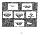
- FIG. 1 is a block diagram of a vehicle warning system 10 according to the present invention.
- FIG. 2 is diagram illustrating the vehicle warning system located at a railroad crossing.
- FIG. 3 is a block diagram of the locomotive communications control system that operates within a warning system of the present invention.
- FIG. 4 is a block diagram that illustrates the interaction of a locomotive with a master controller and the controllers of a warning system located at a railroad crossing.
- FIG. 5A illustrates a block diagram of the transceiver that forms a part of the control system of the warning system of the present invention.
- FIG. 5B illustrates the schematic diagram of the transceiver of FIG. 5A .
- FIG. 5C illustrates a block diagram of another embodiment of the transceiver used in the warning system of the present invention.
- FIG. 6A illustrates a schematic of one of the processors for the warning system of the present invention.
- FIG. 6B illustrates a schematic of another embodiment of the processors for the warning system of the present invention.
- FIG. 7 illustrates a schematic of a magnetometer sensor detector used in the warning system of the present invention.
- FIG. 8 illustrates a flow chart for the timing synchronization between the controllers of the warning system and a GPS system.
- FIG. 9A illustrates a locomotive communication sequence according to the present invention.
- FIG. 9B illustrates an example of a railroad crossing communication sequence according to the present invention.
- FIG. 10 illustrates a sequence of communications windows that occur within a two-second window as part of the warning system of the present invention.
- FIG. 11A illustrates the arbitration time slots for up to eight locomotives.
- FIG. 11B illustrates an expanded view for each of the locomotive arbitration time slots.
- FIG. 11C illustrates the arbitration scheme for four known locomotives.
- FIG. 11D illustrates an arbitration scheme to address the situation of a locomotive that drops out of communications range.
- FIG. 12 illustrates a locomotive begin transmission with its respective time slots operating within the warning system of the present invention.
- FIG. 13A illustrates the basic framework for inter-crossing communications according to the present invention.
- FIG. 13B illustrates an installation of the warning system according to the present invention.
- FIG. 13C illustrates the system waking up upon detecting a beacon transmission from a locomotive.
- FIG. 13D illustrates the warning system waking up irrespective of a locomotive or housekeeping.
- FIG. 13E illustrates the status of other controllers on the crossing as the master controller is being powered up for the first time.
- FIG. 13F illustrates how the master controller assigns time slots to itself and to the slave controller.
- FIG. 13G illustrates the master controller assigning a time slot to one of the advanced warning controllers.
- FIG. 13H illustrates the master controller sending GPS data to all of the units within its control.
- FIG. 14A illustrates the basic scheme for locomotive acknowledgement within the warning system of the present invention.
- FIG. 14B illustrates an arbitration for a railroad crossing from the master controller to the locomotive.
- FIG. 14C illustrates an arbitration for crossing where there are three requests for acknowledgement made to a locomotive.
- FIG. 14D illustrates a token communication window for sending large blocks of data.
- the present invention provides an autonomous vehicle collision/crossing warning system that is both low cost and highly reliable.
- warning systems are to notify vehicles and/or stationery objects such as warning indicators of the approach and/or proximity of a vehicle.
- Examples of such warning systems include railroad crossing warning systems, emergency vehicle traffic light override systems, automobile navigation systems, airport and construction zone vehicle tracking systems and other navigational control and warning systems.
- the present invention is applicable to a wide variety of vehicles, including trains, automobiles, trucks, boats, ships and any other mobile land or water craft.
- the present invention may also be used with a wide variety of stationary objects, such a warning systems, traffic lights, traffic control devices and the like.
- the present invention is not suited for use as a vehicle warning system for aircraft. While the preferred embodiment of the present invention will be described with respect to a highway-rail intersection system, it will be understood that the warning system of the present invention is equally applicable to any of the warning systems or vehicles just described.
- the highway-rail intersection warning system of the present invention is self-contained, powered by solar cells with battery backup, and does not require costly phone line or power installations.
- Components of the warning system include built in safety redundancy capabilities to ensure continuous operation in case an advanced warning sign or a cross-buck sign were damaged in an accident. The remaining functional devices would provide notification of a problem to a fault notification center, and to the next intersection, informing them that two intersection components at a “damaged” intersection were no longer operational. If all four units of a typical installation were damaged the smart Self Updating adaptive mapping system in the locomotive would notify the engineer and the fault notification center.
- An advantage to the present invention is that Time Division Multiple (or Multiplexed) Access (TDMA) communications are used in the control system, which permits several devices, such as the locomotive, crossing, and advanced warning devices, to share a common radio frequency without interfering with each other.
- TDMA Time Division Multiple
- the warning system of the present invention uses precision timing derived from the GPS satellite system and pre-assigned timeslots for specific device communications activities. In this manner, for example, up to 8 locomotives can communicate with an individual intersection without interfering with each other. Timeslots and maintenance of precision timing lets the system operate without a Master Network controller as is used in prior art systems.
- FIGS. 1 and 2 illustrate one embodiment of a vehicle warning system 10 according to the present invention.
- system 10 includes a master control system or controller 20 (located on one side of a railroad track or intersection 12 ), a slave control system or controller 30 (located on the other side of track 12 opposite master controller 20 ), and two advanced warning control system or controllers 40 and 50 (located on opposite sides of track 12 ).
- System 10 further includes a vehicle control system or controller 60 that is located on a moving vehicle (in this example, a locomotive).
- Master controller 20 controls the communications between itself and the crossing slave units (e.g., controllers 30 , 40 and 50 ).
- Controller 20 includes a GPS (global positioning system) receiver and provides the primary listening communications link to the vehicle controller (e.g., vehicle controller arrangement 60 ).
- Controller 20 is mounted on a cross-buck 14 and includes solar power cells, batteries, and dual double sided LED lights for optimum visibility to motorists approaching the intersection.
- controller 20 houses the crossing GPS and one of two ultra-sonic locomotive detection sensors, which are used to validate that the crossing is occupied by a railcar or any other vehicle, or if the crossing is clear.
- Slave controller 30 is mounted on cross-buck 16 and includes most of the components that are in the master controller except for the GPS receiver. Both controllers have ultra-sonic locomotive detection sensors that “PING” and analyze the returned echo to establish the status of the crossing or to time the locomotive entrance and exit from the crossing for evaluation purposes. The sensors may also be used to determine, in conjunction with the precision navigation system on the locomotive, where the actual end of locomotive is, i.e. real length of locomotive. In a related embodiment, the ultra-sonic locomotive detectors can be substituted with magnetometer sensors. This embodiment will be discussed in detail later in the specification.
- Advanced warning controllers 40 and 50 include most of the components that are in the slave controller except for the advanced warning sensors (e.g., ultra-sonic or magnetometer sensors). To conserve power, controllers 40 and 50 “SLEEP” most of the time and are awakened at periodic intervals to be told a locomotive or a vehicle is approaching the intersection or crossing and to stay awake during activation. Two advanced warning controllers are used and are installed on each side of the track on advanced railroad warning signs 18 to warn drivers that they are approaching a railroad crossing or intersection. Controllers 40 and 50 depend on a timeslot strategy that is used by the entire warning system 10 to conserve energy. All crossing devices maintain time synchronization to a GPS derived clock of controller 20 . This ensures accurate timeslot management by all devices system 10 . System 10 further includes a locomotive (or vehicle) controller 60 used by any locomotive crossing the intersection.
- SLEEP SLEEP
- controllers 40 and 50 “SLEEP” most of the time and are awakened at periodic intervals to be told a locomotive or a vehicle is approaching the intersection or
- System 10 “wakes up”, when a locomotive is approaching from either direction, and provides a warning 30-seconds before the locomotive arrives at the intersection.
- the early advance warning is intended to provide drivers with enough time to take appropriate action.
- System 10 will continue flashing until after the locomotive has passed and all railcars have cleared the intersection. In the event that one of the signs has been damaged in an accident, the other signs will still continue to operate providing their advanced warning.
- a system problem message will be forwarded to a fault notification center.
- the railroad engineer/conductor will have available a handheld (or systems mounted) Locomotive Data Entry and Display module ( FIG. 3 ).
- system 10 communicates with the intersection and activates the intersection.
- the engineer receives a system-activated notice, or in case of problems (for example damage to one of the signs equipped with a controller) the Data Display unit will notify the engineer of the problem. It will also notify the fault notification center via cell phone of the problem.
- the advance warning and cross-buck signs will have been activated and flashing warnings to motorists.
- the Data Entry module is also used to enter the number of cars for locomotive length in backing situations.
- System 10 also uses a Smart Self Updating System (SSUS) to poll the crossing and share the latest systems information. In this way, as the locomotive moves down the track it is also updating itself and all crossings along the line with the latest system information. Using the SSUS will require no input on the locomotive engineers part. Furthermore, a locomotive equipped with a controller 60 including SSUS, does not need to be programmed by the engineer. System 10 receives all its updated system information from the first intersection it approaches. At this time it will know what to expect as it continues down line. This information will be useful at times when all system 10 components at one of the equipped intersections has been damaged. This event of total system failure of all components at an intersection will be known by the approaching locomotive equipped with controller 60 . The engineer will be notified as well as the fault notification center.
- SSUS Smart Self Updating System
- System 10 will in turn pass this information along to the next intersection, and thereby all locomotives approaching the intersections it has passed. Only, when the locomotive is backing, and there will be a significant number of new of railcars aided to the locomotive, will the engineer need to update system 10 with the total number of cars. In this example embodiment, as the last car of the locomotive exits the intersection the flashing lights will be deactivated and the system will wait for the next locomotive to approach.
- Each locomotive SSUS contains a database of the status of all known crossings and each crossing controller has a copy of a smaller localized database. Each time a locomotive and crossing interact, the databases are compared and whoever has the latest information, passes this data to the other. In this manner, locomotives will have the most up to date status of the system. To achieve the high reliability in this system, any of system 10 components could communicate with the locomotive in the event of a Master controller failure. If a locomotive is new to an intersection it will have learned of that intersection from the previous intersection. In the event of a total system 10 failure (from vandalism or an act of God) the locomotive will have prior warning of the problem, giving a warning to the engineer and providing notification to the fault notification center.
- Locomotives as they travel the system, will receive notifications from partially failed crossings through the MAYDAY broadcasts.
- a locomotive with a new advanced warning system can enter its first system 10 equipped highway intersection and receive the latest system updates for all the warning systems in that area. This information is then propagated from locomotive to the warning system, and vise-versa as required.
- system 10 uses the locomotive as a platform for a BEACON signal that is transmitted every 4 seconds in a timeslot.
- the BEACON contains geographic location information about the locomotives position, speed, direction of locomotive motion and heading. This information is obtained from a precision DGPS (differential) receiver on the locomotive. Any crossing can listen to any locomotive at all times, if the locomotive is within radio range of the crossing.
- DGPS differential
- Controller 20 contains a powerful 16 bit microcomputer (and DGPS and transmitter) that compares its location, derived from it's onboard DGPS receiver, to that of the locomotive data derived from the BEACON transmission and decides if the locomotive is approaching the crossing and activation needs to occur. Once activation has occurred master controller 20 can optionally notify the locomotive that the crossing is activated. Master controller 20 also controls the other warning devices in system 10 and collects information about the state of each device such as the battery and whether a self-test of on-board devices was successful. As the locomotive enters the crossing, a set of ultra-sonic sensors connected to master controller 20 and another set connected to slave controller 30 confirms the crossing. Master controller 20 also deactivates the crossing when the locomotive has passed. The same sensors are used for locomotive cars left on the crossing.
- any of the controllers disposed on the crossing posts can operate as the master controller in the event master controller 20 fails. Because system 10 maintains a continuous dialogue between devices, the devices can very quickly detect abnormal behaviors and respond with a call for help, referred to as a MAYDAY. Any crossing device can initiate a MAYDAY. This transmission is made anytime a locomotive is in listening range to the crossing even if the locomotive will never intersect the crossing. This ensures prompt reporting of failed crossing devices due to the immediate call the locomotive controller 60 places to the fault notification center.
- all crossing system components mount on existing structures with no addition construction required in most instances.
- all crossing devices are totally self-contained and mount as a single unit.
- All crossing components use extremely long life Lithium Ion battery technology, combined with a high efficiency solar panel.
- the battery pack is designed to provide 5 full days of operation with minimal solar input.
- the battery pack uses state of the art long life, low temperature operation AGM(Absorbed Glass Mat) Sealed Lead Acid (e.g., Concord SunXtender PVX1234T battery).
- the overall crossing system design allows most active components to “SLEEP” in an inactive state and be awakened based on the Timeslot communications scheme to be described later. This allows for extremely low power drain on the system, permitting smaller batteries, and solar panels.
- Each station or location at the crossing is totally self contained such that no wiring or construction is needed to install the system.
- FIG. 3 illustrates the locomotive control system or controller 60 that includes: a DGPS receiver 61 , a digital radio 62 , a cell phone and modem 63 , a processor 64 , a mass storage device 65 , and a key pad and display 66 .
- a locomotive equipped with controller 60 and a crossing with master controller 20 has GPS location data on board. This data allows the system to know about the devices by geo-location. Knowing about the location of a crossing and knowing where the locomotive is, the system can cross check if it is approaching a crossing and has not gotten a confirmation that the crossing is activated. This is the fail-safe for a totally broken crossing. In system 10 , if the locomotive knows about a crossing, it cannot forecast that it should have received a confirmation and warn the engineer. Typically the locomotive does not need to know there is a crossing ahead because, if the crossing is working, the locomotive beacon will cause it to activate. When the crossing activates, it sends geo-location data to the locomotive, which causes the locomotive to “discover” the presence of the crossing. This discovery process causes the locomotive to learn about this “new” crossing. Data about the new crossing is placed in the locomotives' database.
- Database 65 of the locomotive controller 60 contains the geo-location and track direction through the crossing.
- the Master controller at the crossing knows its location from its own on-board GPS, so as soon as a new crossing is turned on it has this data with no human intervention. This is stored as 4 bytes for milli-arc-seconds of latitude, 4 bytes for milli-arc-seconds of longitude and two bytes indicating compass direction of the rails through the crossing. In the last two bytes the crossing status is also encoded. It has been estimated that there 260,000 crossings in the US, therefore to store the entire US crossing database requires less that 3 megabytes of flash memory in the locomotive while the crossings will only store a localized map of their individual surroundings.
- the warning system uses to its advantage the fact that the locomotive cannot be in California and Maine at the same time.
- the locomotive is in Minnesota, so only data that is within a grid of one degree by one degree, is actual exchanged during the dialogue. This would typically be less than a few hundred crossings.
- CRC Cyclic Redundancy Check
- data is stored in the crossings based on a 1 degree, which is approximately 60 NM by 60 NM or a 69 by 69 statute mile grid.
- the crossing data has the crossing in the center of the grid.
- the locomotive receives the location of the crossing and uses this location to generate a CRC on the same grid data and then compares this with the CRC sent from the crossing. If the databases match, no exchange occurs, if not then an update exchange takes place based on the latest data.
- the latest data is determined by comparing all locomotive time stamped entries with-in the prescribed grid with the database time stamp from the crossing. The device with the latest data sends this data to the other.
- the system architecture of system 10 is based on a Time Division Multiple Access (TDMA) wireless communications system using a dedicated radio frequency for transmission of data between the locomotive(s) and crossing(s) (see FIGS. 1 and 2 ).
- System 10 uses precision Differential Global Positioning System (DGPS) navigation methods to determine distance of the locomotive or locomotive from an individual crossing. All arrival and departure calculations are done at the individual crossing sites.
- the locomotive's controller 60 is primarily responsible for generating a BEACON broadcast used in the crossing arrival and departure calculations.
- the BEACON conveys latitude, longitude, heading, speed, length and backing status.
- Locomotive controller 60 is also responsible for collecting and storing status data from working crossings and relaying fault notifications from failed crossing.
- the system 10 architecture makes optimum use of power, hardware and communications bandwidth to provide a safer more effective system for advanced warning activation.
- the use of DGPS provides precise location of locomotives and precision timing for communications.
- the System also uses the number of locomotive cars to compute end of locomotive location relative to the crossing.
- Precision DGPS timing is used to synchronize controller 20 intersection radio network and provide for TDMA (Time Division Multiple Access) control of communications within warning system 10 .
- TDMA Time Division Multiple Access
- all field devices use TDMA and the radio network to allow for minimum power consumption through the use of a concept referred to as “SLEEP”.
- the concept of “SLEEP” permits devices to essentially go into “hibernation” and consume very low power, then awaken at appropriate times to respond to communications from other devices.
- the SLEEP architecture permits very economical implementation of battery and solar power systems for field devices and lowers installation costs.
- system 10 uses solar cells manufactured by Solarex (model SX-30), which are a multi-crystal solar electric cell that provides photovoltaic power for general use. They operate DC loads directly or, in an inverter-equipped system, AC loads.
- DGPS receiver 61 operates in a DGPS mode to provide ⁇ 5 meter RMS fixes on location.
- the radio system 62 provides for beacon broadcasts to all warning system 10 equipped crossings and receives information from crossings.
- Processor 64 provides control of radio communications, generates position information and logs data for system performance evaluation.
- the Engine interface to the processor provides accurate low velocity locomotive position data for use in dead reckoning.
- a keypad and display provides a means for the locomotive crews to monitor the system and enter data about the locomotive such as number of cars, as needed.
- Cell phone modem 63 is used to report system faults and for doing data collection remotely.
- Controller 60 controls the transmission of beacons to surrounding warning system 10 crossings by using precise DGPS derived timing to transmit these beacons and network status data at the correct time interval or timeslot.
- the crossings listen in appropriate timeslots for controller 60 beacon broadcasts.
- the timeslot control also ensures that the beacon of controller 60 does not unintentionally interfere with local crossing system communications, as the crossing system communicates within itself during a different time interval than the beacon broadcast from controller 60 .
- all warning system 10 controllers have built in diagnostics to verify that the flashers work and the status of the batteries are known at all times for all devices.
- FIG. 4 illustrates how the locomotive with controller 60 interacts via messaging with the controllers located at a crossing (or intersection).
- the crossing controllers wake up and remain in a state of alert until the locomotive has passed.
- the timeslot strategy ensures that a wakeup cycle occurs every 4 seconds corresponding to the locomotive beacon transmission.
- the speed of the locomotive and the distance at which the radio network communicates gives a several minute margin between locomotive controller 60 wake up and the crossing activation.
- controller 60 messages to the crossing, using 2 watts of power, speed and position data via the beacon; or an acknowledgement or uploads data.
- the locomotive receives messages: crossing activated/deactivated; upload data; or MAYDAY signal.
- messages received include: enter standby mode; activate warning and provide acknowledgement or deactivate warning and acknowledge.
- Any non-functioning crossing device(s) are detected and an alarm is sent in a special timeslot called the MAYDAY mode.
- Each of the controllers of system 10 are capable of acting as MAYDAY senders in the event of a detected crossing failure.
- Loss of master controller 20 is detectable by any of the crossing slave controllers or the advanced warning controllers because of periodic polling between master and slave devices. If the Slave devices detect a number of missed polls by their master 20 , they will enter a MAYDAY mode in which they will take turns, to maximize battery life, sending the MAYDAY broadcast to any locomotives in the area. All remaining slave units will continue to function, and any remaining device can control the intersection.
- slave devices will resynchronize their time-base communications by using locomotive controller 60 and its beacon derived timing allowing proper timeslot operation. This feature ensures that faults get reported as soon as possible, even if the locomotive detecting the MAYDAY broadcast is not dealing with the failed intersection.
- the MAYDAY is sent on a higher power, i.e. 2 watts to ensure maximum range. Further, the MAYDAY is only active during times the warning system 10 at the crossing hears a beacon broadcast from a locomotive. MAYDAY broadcasts include geo-location data of the failed crossing. This information is then relayed via the cell phone modem in the locomotive to the designated responders.
- Systems 10 use 1 narrow band FM channel in the VHF or UHF band.
- System 10 uses 2 watts for locomotive BEACON broadcasts and 100 mw for crossing intercommunications. Crossings preferably use 2 watts for MAYDAY transmissions when attempting to notify a nearby locomotive. Multiple transmitters are managed through the use of a TDMA control scheme using DGPS timing corrections for network synchronization.
- FIGS. 5A and 5B a block, diagram and a schematic diagram illustrate, respectively, a preferred embodiment of a transceiver that is used in system 10 .
- System 10 communications are based on the use of a narrow band (5 KHz channel) FM radio system and uses GMSK FM modulation to transmit at 4800 BPS data rates.
- the 8 MHz oscillator 102 is composed of Q 2 , Xt 2 , D 2 , C 100 , C 122 , C 34 , C 98 , C 99 and resistors R 46 , R 63 and R 67 (see FIG. 5B ).
- This is a modified Clapp oscillator, with varactor diode D 2 being the tuning element.
- Application of a DC voltage will cause D 2 to decrease its capacitance, which in turn causes crystal XT 2 to shift its frequency upward.
- no modulation applied capacitor C 122 is adjusted for exactly 8 Mhz oscillator frequency.
- the modulator 101 is composed of CMOS Switch IC- 10 that connects the varactor diode to either the Receiver Frequency Adjust Pot R 81 or to the Modulation source from the output of IC 8 A-pin 1 .
- the choice of inputs to the varactor diode is determined by the TX/RX signal at pin 1 of IC- 10 .
- Pot VR 6 adjusts the modulator DC level to provide 8 MHz output from crystal with no AC modulation applied.
- the modulated or static 8 MHz frequency signal is applied to Synthesizer ( 104 ) IC- 3 . This 8 MHz frequency is divided internally by synthesizer 104 to obtain a 4 MHz reference frequency.
- This reference is compared to the output of the VCO signal from IC 6 pin 5 , when in the transmit mode, should be 221.9525 MHz.
- Synthesizer 104 then divides this 221.9525 MHz frequency to equal 4 MHz. Any error between the reference and the divided VCO will produce a voltage which represents this error. This voltage is applied to varactor diode D 1 of oscillator 106 to tune the VCO to the correct frequency. Capacitor C 2 adjusts the center frequency of the VCO. Because the VCO must produce two frequencies, one for transmit at 221.9525 MHz and 243.3525 MHz, synthesizer 104 get reprogrammed between Transmit Mode and Receive modes to change the internal divisor to allow generation of either frequency from the same 8 MHz reference.
- Synthesizer 104 requires a short period of time for it to switch frequencies. During this time the LOCK signal is false. This LOCK signal is used to prevent transmission until the VCO has stabilized at the correct frequency. Buffer amplifier IC 6 108 supplies the frequency to both the transmitter and receiver sections.
- Transmitter DC power is controlled by transistor Q 4 , Q 7 , Q 8 and Q 9 ( 110 ).
- the components serve to inhibit application of DC power to the transmitter power amplifier 112 until we have Synthesizer LOCK and TX Mode is true.
- Power amplifier ( 112 ) IC- 15 amplifies the RF signal from IC 6 to the desired transmit level and feeds this signal to the PIN diode switching network 114 composed of PIN Diodes D 5 , D 6 . D 7 and associated components.
- the PIN Diodes are forward biased in a manner to short the receiver input to ground and couple the transmitter output to the antenna matching network 116 made up of L 14 , L 15 , L 26 and associated components.
- the matching network 116 acts as a low pass filter to remove out of band energy and to match impedance to the antenna 50 .
- the receiver is a dual conversion super heterodyne design using 21.4 MHz as its 1 st IF and 455 KHz as its second IF. Because of the extreme close channel spacing at the operating frequency, (5 KHz), the receiver is designed to provide very narrow reception. The bandwidth is less than 3.5 KHz.
- filters are used to produce this very narrow response, including a 221 MHz helical filter # 1 ( 118 ), receiver RF amplifier 120 , 221 MHz helical filter # 2 ( 112 ). These components serve to reject out of band signals and provide a small gain in the signal. There are 4 poles of helical filter employed.
- a 1 st mixer (221 to 21.4) ( 124 ), 21.4 MHz 4 pole crystal filter, 2 nd mixer and 21.9450 MHz oscillator perform the conversion from 221.9525 MHz to the 21.4 crystal IF filter center frequency.
- the mixer portion 124 of IC 2 receives the 243.3525 MHz frequency from synthesizer 104 and mixes it with the 221.9525 MHz signal and produces 21.4 MHz, the difference.
- the 21.4 MHz is then passed through the 4 pole 21.4 crystal filter 126 . This signal from the crystal filter is then fed into the second mixer stage in IC 1 ( 128 ) where it is mixed with 20.9450 MHz to produce a difference signal of 455 KHz.
- KHz 2 nd IF # 1 ( 130 ), 455 KHz IF amplifier 132 , 455 KHz 2 nd IF filter # 2 ( 134 ) serve to limit the input signal by providing a very high level of amplification at 455 KHz frequency. This limiting removes AM components of the signal and it is then fed to the quad detector for conversion from FM to audio.
- a quadrature detector 136 , audio amplifier 138 and filter, carrier detector ( 140 ) recover the original FM modulated data from the 455 KHz if signal and filter it to remove the by products of the conversion and provide the audio to the modem on the main CPV board.
- a carrier detect signal is also provided by IC 1 . This signal is used to determine if a carrier at the 221.9525 MHz frequency is available.
- a block diagram illustrates another embodiment of a transceiver 150 connected to a processor designed in accordance with a preferred embodiment of the communication protocol of an autonomous vehicle warning system of the present invention.
- the transmitter section includes a transmit PI network 152 connected to a power amplifier 154 and then to a buffer/IF amplifier 156 .
- Buffer amplifier 156 is connected to a synthesizer 158 that is connected to a voltage controlled and temperature compensated oscillator 160 that is then connected to a modem 162 .
- the receiver includes a resonator 164 connected to a linear amplifier 166 and to a mixer 168 , with the mixer receiving a 220 MHz input from synthesizer 158 .
- Mixer 168 is connected to a 21 MHz crystal filter 170 and to a mixer 172 that is connected to a 21 MHz oscillator.
- Mixer 172 is also connected to a 455 MHz IF filter 174 that is connected to a 2 nd IF filter and quad detector 176 .
- FIGS. 6A-6B illustrate schematics of the processor and subsystems for warning system 10 .
- FIGS. 6A and 6B illustrate processors 200 A and 200 B, respectively, that are the heart of warning system 10 .
- Several switched supply circuits 202 A and 202 B are shown as well as a data modem 204 A and 204 B for receive and transmit capabilities.
- Flash controls 206 A and 206 B and solar battery charger circuits 208 A and 208 B are also illustrated.
- FIG. 7 illustrates a schematic of a magnetometer sensor detector 250 used as a substitute for the ultra-sonic sensors in warning system 10 .
- the magnetometer sensor detects a train approaching or departing the crossing depending on changes in the magnetic field around the sensor caused by the size of the train.
- Magnetometer includes an IC device 252 connected to a photocell module 254 for power that is connected to a resistor 256 and transistors 256 and 258 .
- Each magnetometer channel is read through an A/D converter that outputs a value between ⁇ 4095 and 4096. Both channels are “zeroed” to mid-scale. The two channels are physically oriented so that when a train passes the crossing, one channel increases its signal and the other decreases its signal.
- Each magnetometer channel is read every 1 ⁇ 8 th of a second. After each reading of the magnetometer the difference between the channels is calculated and stored. The difference data is filtered by averaging the last 16 stored values.
- Two separate XBARR calculations are performed on the last 64 (8 sub-groups of 8 readings each) filtered readings. Each of these calculations produces upper and lower control limits. One set of limits is used to determine the beginning of a train detection event (in limits). The other set is used to determine the end of a train detection event (out limits). These calculations are performed after each reading except when in a train event; the out limits already calculated are used until the end of the train event. Control limits only on the background data only. The new filtered data is tested to see if it is inside or outside the control limits. A train detection event is started when 90 percent of the last 8 filtered readings are outside the XBARR in limits. A train detection event is ended when 90 percent of the last 16 filtered readings are inside the XBARR out limits.
- the filtering and XBARR calculation require 80 readings to be buffered, so no detection is possible for the first 10 seconds.
- the 10 second delay is also used after train detection events end to be sure that no event data is used to calculate new control limits.
- the magnetometer is reset or re-balanced after each train event.
- Power consumption is one of the challenges in implementing a warning system in remote locations utilizing solar power and batteries only.
- a locomotive or vehicle operating within the warning system does not have a power problem since both the vehicle and the locomotive are powered with generators. Therefore, a GPS receiver connected to the controllers can stay on at all times. However, the GPS receiver and the controllers located at the intersection need to transition into a “sleep state” in order to preserve power.
- the primary microprocessor in each controller goes to sleep and wakes up based on its 32 KHz clock. All of the devices in the warning system then wake up at exactly the same time to determine if a signal is being transmitted from an approaching locomotive. In this example embodiment, the goal is to minimize the size of the solar panel to keep the cost down.
- the devices wake up every two seconds and listen to see if signals are being actively transmitted. If no signal is detected within the first 10 milliseconds of waking up, the microprocessor determines that no signal is present and returns to its sleep state. It is important that all of the devices of the warning system wake up and sleep at exactly the same time to ensure synchronized communication with each other and with an approaching locomotive.
- the devices or controllers located at the railroad crossing experience drift in their crystal oscillators due to temperature and other factors and so there is a need to periodically resynchronize the clock within the microprocessors with a stable clock source.
- the GPS clock is used as the stable clock source.
- the GPS receivers at the crossings are also transitioned into a sleep state.
- the entire system wakes up and the GPS receiver requires the satellites, requires its positions, requires its timing synchronization from the satellites and then the software in the microprocessor acknowledges that it must divide its crystal oscillator frequency by 32,768.
- a one-second pulse should result indicating the one pulse per second in that frequency. If the crystal has drifted and it is putting out 32,772, for example, the frequency would be 4 hertz too high.
- the microprocessor determines that the crystal oscillator must be compensated in order to bring the crystal back to 32,768 hertz to ensure the controllers in the warning system are in synchronization with each other and with the approaching locomotive.
- the microprocessor uses the 32,772 as the divider to generate the one second clock that is used for comparing with the GPS retrieve time stamp.
- the microprocessor compensates for the error in the crystal oscillator based on comparing it with the one second pulse that is generated by the GPS receiver.
- a set of flowcharts 300 A and 300 B illustrate the process for calibration of the timers in the crossing controllers using the GPS clock. All critical tasks are dependent on precise timing synchronization with the GPS clock.
- the GPS receiver When the GPS receiver is on, the GPS continuously sends out serial data to the microprocessor.
- a complete GPS packet is received, a task is placed into the low-priority task queue to process the GPS packet (since the timing-critical portion of the GPS signal arrives via a different interrupt).
- the GPS packets are then split out into position, time, and other parameters.
- the GPS also emits a one pulse-per-second (PPS) interrupt. In normal operation, a GPS time packet indicating that this pulse is valid is generated about 400 ms before the actual 1 PPS interrupt.
- PPS pulse-per-second
- Running concurrently with this interrupt is a counter based on a 32.768 kHz crystal.
- the flow of events for each interrupt effectively synchronizes the counter with the GPS interrupt.
- the GPS runs for about 10 minutes on startup to synchronize with the counter, then runs for about 1 minute every hour after initial synchronization to maintain synchronization within the required tolerance for this system.
- the timer determines that an hour has gone by it issues a task to the task queue instructing the main loop to re-enable the GPS and resynchronize.
- the resynchronization can be implemented once every 15 minutes up to once every four hours.
- a timed-event queue has also been implemented. For example, every time the synchronized timer or 1 PPS GPS clock detect the occurrence of an even-numbered second, 6 timed events are scheduled, corresponding to each of the phases of the communications protocol: initial wake-up, locomotive arbitration, locomotive BEACON transmissions, crossing housekeeping, crossing acknowledgement, and token/map data communication. These events are scheduled to happen at 0 ms, 25 ms, 130 ms, 675 ms, 1000 ms, and 1500 ms, respectively. As each timed event expires, the task corresponding to each event is placed into the task queue by the event timer. The main loop receives these tasks (all high priority tasks due to their timing sensitive nature) and processes them as they are scheduled to happen.
- a brief review of the synchronization process between the GPS and the timer and flowcharts 300 A and 300 B indicates that upon a GPS interrupt start at step 302 A the system determines whether to start calibration or not. If not at step 304 A, the system determines if it is in calibration mode. If the system is not in calibration mode at step 306 A, the system determines whether there is enough calibration and finally in step 308 A if there is not enough calibration then the GPS one pulse per second interrupt ends. With respect to flowchart 300 B and the timer, the timer also follows a similar sequence of queries 302 B through 306 B but includes an additional step 307 of determining whether long term calibration is necessary. If such calibration is not necessary then the process proceeds to step 308 B, the system determines to end timer interrupt.
- the system may count rollovers in step 316 if it is in the calibration mode or schedule a radio task on an even second count at step 318 if there is enough calibration or start the GPS calibration mode at step 320 if long term calibration is required.
- calibration can start at step 310 with the prerun timer which will then end the GPS interrupt.
- step 312 if the system is in calibration mode, the calibration will be computed and a radio task on an even second count will be scheduled.
- step 314 if there is enough calibration, the timer starts and then proceeds eventually to end the GPS interrupt.
- a network controller with a central database is not necessary to keep track of the addresses of the various controllers in the warning system.
- the controllers at the crossings do not necessarily require assigned addresses upon initial installation.
- the present invention utilizes the geo position, the latitude/longitude coordinates provided by the GPS as an address. After a crossing controller is installed on a cross buck with a GPS receiver, the controller will wake up, retrieve its location using the GPS receiver and its latitude and longitude coordinates, and from that point on the controller uses as its address the geoposition. This will also be the controller's address in the locomotive database. As the locomotive is moving through the system, it can say I'm at Waseca, Minn.
- latitude X/longitude Y latitude X/longitude Y
- the latitude and longitude generated by the GPS receiver at the crossings also serves a purpose other than for timing synchronization.
- the locomotive can be advised of its correct location in the event there is a problem with the GPS system in a particular location using differential GPS.
- the controllers can provide the corrections to the GPS reception of the locomotive.
- two flowcharts 400 A and 400 B respectively, illustrate two-second communications sequences for a locomotive and a crossing.
- communications protocol tasks are loaded into the timer event queue when an even-second task is processed since communications tasks are high priority.
- the task queue is actually made up of two queues: one queue is for high priority tasks, such as radio communication, and the second queue is for low priority software maintenance tasks (such as reading the temperature, maintaining the real-time clock, etc.) Tasks are always fetched and executed from the high priority queue first. After all the high priority tasks are executed, low priority tasks are given a chance to execute. Due to the timing critical nature of the high priority tasks, the low priority tasks are time-limited to less than 100 ⁇ s execution time. Regardless of the priority the task, all tasks are internally guarded by an event timer to not exceed a specific time allocation.
- FIG. 9A is an example of a locomotive 2-second communications sequence 400 A that includes five steps that are queued up as timer events. As the timer expires each event in order, a task is pushed onto the task queue. The main loop reads each consecutive task out of the task queue and processes it in turn. With respect to step 402 A, the locomotive transmits a 10 millisecond transmit key which is then followed by a time slot arbitration at step 404 A. Once the time slot arbitration time has expired, the train transmits the beacon signal at step 406 A and then at step 408 A the train listens for an acknowledgement or a signal from the crossing. At step 410 the controller on the train determines if there is a need to exchange map data with the crossing based on the feedback from the crossing at step 408 A. If so, the exchange data is performed and the transmission ends.
- FIG. 9B is an example of a crossing 2-second communications sequence 400 B that corresponds to the steps of process 400 A.
- these five tasks are all scheduled as timer events initially. As the timer reaches the scheduled time for each event, the corresponding task is pushed onto the task queue where the main task is pushed onto the task queue where the main task handling loop performs the appropriate actions.
- the crossing at step 402 B waits for the millisecond transmit key or performed housekeeping processes until it is timed out.
- step 404 B if a transmit key is received from a locomotive, then the crossing controllers listen for a locomotive arbitration until the step times out.
- the crossing controllers conduct housekeeping if housekeeping is in order or if there is a transmit key to the locomotive.
- the crossing controllers perform an acknowledge function if a beacon signal is detected from the locomotive.
- the crossing controllers will perform an update of map data in response to the beacon data from the locomotive after which the sequence for the crossing ends.
- a short window at time T 0 is used as a “wake up”. Any device that will transmit any data must use this window first to tell the—“wake up and listen”. If it hears this window it knows to listen more. If a master controller at a stationary warning crossing wants to talk to its slaves it must use this window to tell the slave controllers to wake up and listen. Every locomotive broadcasts in this window prior to sending the beacon. Typically the intersection controllers will only listen to this and can sleep the other part of their days. T 0 lasts for 1 ms+10 ms+1 ms+1 ms dead band for 13 ms, which gives T 1 at 13 ms or beyond. As an example, choosing 25 ms gives flexibility in the wakeup. In 10 ms may not be possible to send out the header, which takes 12 ms. This wakeup is just a carrier detect and lock.
- FIGS. 11A-11D are a series of time slot diagrams illustrating locomotive radio communications when multiple locomotives are communicating simultaneously with warning system 10 .
- the communications protocol allows 8 locomotives in any communication grid (see FIG. 11A ).
- This scheme uses the beginning interval of the BEACON transmission from the locomotive to encode the active channels that are being used.
- This encoding is the network protocol, which allows the locomotives to chose the correct channel for data transmit.
- the first half of this time slot performs the locomotive arbitration while the second half is the actual beacon transmit. Adding a locomotive will cost 12 ms+67 ms for 79 ms in total of time.
- the arbitration preferably is performed with a 2 ms carrier detect.
- a 1 -A 8 are divided in to 3, 4 ms windows each for 24 sub windows.
- the total Arbitration is 0.096 seconds.
- locomotive # 1 is in time slot A 1 then it will randomly transmit its arbitration beacon in 1 of the 3 sub slots of A 1 while listening to all other 23 slots.
- the locomotive will ask: A) whether another locomotive in the same slot, and B) what time slots are being used. If locomotive A and locomotive B are in Beacon slot 1 they randomly transmit their arbitration in one of the 3 arbitration sub slots, A 1 . 1 -A 1 . 3 . If locomotives hear other locomotives in their arbitration window they know two or more locomotives are in the same beacon interval, which should be avoided.
- the locomotives next determine who was 1 st , 2 nd and so on.
- the first sub-slot will stay in the first beacon time window.
- the second will take the second beacon channel and the third the next.
- FIG. 11C illustrates the arbitration sequence for 4 known locomotives; two or more are in A 1 , one is in A 2 and at least 1 is in time slot A 3 .
- the arbitration sequence is as follows:
- Arbitration 1 The first locomotive was A 1 . 1 . This locomotive will stay in slot since he was the first device to use an arbitration slot. The locomotive in time slot A 1 . 3 will move to A 2 since he was the second device to arbitrate a position. This proceeds through all 8 locomotives. Each Beacon window following arbitration will reflect the choices shown in Arbitration 2 .
- Arbitration 2 After arbitration # 1 the locomotives use the assigned beacon position. They will then re-arbitrate at random positions 1 - 3 of their time slot in arbitration # 2 as shown above. The locomotive in time slot # 1 believes he is the only one in one and the first in a string of arbitrations so he will stay there. The locomotive in A 2 . 1 discovers he is the first in A 2 and will stay there as well. The locomotive in A 2 . 3 discovers he was the third and thus should be in beacon slot A 3 and will move to this slot. The locomotive in slot A 3 . 3 discovers he was the fourth and thus should be in A 4 and will move over to this slot. This proceeds down through all slots and locomotives. After arbitration # 2 the locomotives use the assigned beacon position.
- the crossing knows to listen for arbitration.
- the master controller at the crossing will now know many trains are dialoging and in what beacon slots to listen. If no arbitration occurs but A 0 was used the controller knows a master controller is going to transmit or an acknowledge will occur.
- the GPS latitude and longitude is used as the seed for the random number generator.
- FIG. 11D illustrates an arbitration sequence to address the situation of locomotives that drop out of communication range.
- two trains drop out of communication range. These two are either permanently out or range or will fade back in soon. Either way, the algorithm is the same.
- the first arbitration slot goes to A 1 , the second to A 2 and so on.
- Arbitration # 2 the locomotive which was there fades back in. This will force all locomotives after this one to move down one and let the new one in.
- the crossing always knows what slot to listen in and only needs a wake up for the A 0 wake up call every time. By default any locomotive all by itself will be in slot A 1 and beacon # 1 .
- FIG. 12 illustrates a locomotive beacon transmission during operation of warning system 10 .
- the beacon signal occurs after the arbitration and the Locomotive time slot takes into consideration the arbitration results. Every locomotive will transmit a header followed by a data block containing the position, heading and speed of the locomotive.
- FIGS. 13A-13H illustrate the basic framework for inter-crossing communications according to the present invention. All housekeeping is performed at low power (about 100 mw or less), which drastically limas the range f communication and cross talk. In the real world of vehicle warning systems, there is no real control of the installations, the number of devices per crossing or distance between crossings. Thus, there must be another arbitration protocol to clean up the communication and optimization after installation. The concept is for every crossing in range of each other to have a specific time slot. A maximum number of crossing devices per area is first selected. In the preferred protocol, there is a limit of 16 devices in any 300-meter range (see FIG. 13A ). Clusters can overlap and will have unique ID's. The housekeeping is used for status, light on, lights off and so on. It should be noted that the locomotives have a special 0.6 seconds for arbitration, whereas the crossing controllers have no special arbitration time and therefore is provided for in the command structure.
- the controllers in FIG. 13B are initially identified as the Master (XM), Slave (XS) and the two advanced warning controllers (XA).
- the time slot selection will follow this predefined structure and helps to simplify the intercrossing communication protocol.
- the Master controller is located on the North side of the tracks with the Slave being located on the South side.
- the Master will always be on the West side and the SLAVE will always be on the East side.
- the first advanced controller from the Master on the north/west side will be programmed to XA 1 , second XA 2 and so on.
- the first unit on the south/east side would be the next sequential number, XA 3 in this example.
- the sequential members continue increasing as additional XA's are added.
- FIGS. 13C and 13D the details of the preferred embodiment of a Housekeeping Command Protocol is illustrated and described. Where there is no T 0 wakeup, no housekeeping is performed. To conserve power, all units turn on at T 0 to see if anything is going on. In the following case nothing is going on so after 12 ms all units go back to sleep for the remainder of the 2 second communication cycle. This gives a 0.6% wakeup duty when nothing is happening. When there is a wakeup at T 0 and no housekeeping, at T 0 all units wake up and listen. In the following example we see a T 0 wakeup. At this time we do not know if it is a locomotive, housekeeping or both. All units must listen to the beacon arbitration.
- the controller sees 3 of the 24 slots utilized and so it must listen to Beacon 1 , 2 and 3 because there are 3 locomotives.
- the controller issues a wakeup and listens to see if any crossing communications are required. Because it sees no A 1 wakeup, the controllers can sleep again.
- T 0 wakeup with housekeeping preferably all units wake up and listen.
- T 0 wakeup At this time, it is unknown if it is a locomotive, housekeeping or both. All units must listen to the beacon arbitration. If there are no arbitrations, the controller sleeps through the beacon timeframe.
- T 3 the controller performs a wakeup and listens to see if any crossing communications are required. Because A 1 is used but A 2 is not, the controller listens to the masters only. In the above example, it is possible to have had a beacon since it makes no difference to the A 1 wakeup. If a master wants to talk it must occur at wakeup at T 0 and T 3 .
- Time Slot Selection Details of Crossings is described in connection with FIGS. 13E-13H .
- the crossing master On first power up, the crossing master will transmit a status request in the second arbitration slot. This is done at the 100-mw-power level to see all local crossings in radio range with a programmed time slot. Every crossing with a time slot answers with status in its time slot. The new warnings will not answer since they do not have time slot. This teaches the Master what is occurring in his low power environment.
- the MASTER 1 knows which are the open time slots (H 1 -H 5 & H 12 -H 16 ).
- the MASTER 1 was preprogrammed with this size and configuration (such as 4 MASTER 1 /SLAVE 1 /XA 1 /XA 2 ).
- the MASTER 1 will now pick the first open slot and program its slaves 1 by 1 verifying proper time slot progression. In this example, the MASTER 1 will program and receive positive confirmation of SLAVE 1 .
- the MASTER 1 will specify it is talking to any un-programmed SLAVE 1 and will tell the SLAVE 1 what its set time slot will be.
- the SLAVE 1 immediately takes the time slot and responds to the MASTER 1 with the echo of its program command in it programmed slot.
- the SLAVE 1 will now only answer the MASTER 1 in time slot H 1 .
- the SLAVE 1 knows who programmed it and who it should listen to from this point forward.
- the new MASTER 1 After the new MASTER 1 is able to communicate with the SLAVE 1 it will communicate with the XA 1 (next on its control list). This process will follow the same protocol. To save power during installation the MASTER 1 should be the last device to be powered up allowing quick setup and less transmits of setup. Every device must know what it is and every Master must know the total configuration. This will proceed until the MASTER 1 detects that all is well and all units are programmed. The MASTER can verify final installation by requesting a status and hearing back from its own units. Only its units will answer since all XA's and SLAVE's; only listen to the master whom programmed them and answer this master.
- the MASTER 1 With respect to GPS coordinate programming, the MASTER 1 must program all units in its warning system with the proper installed GPS coordinates. This GPS data is only programmed on the first power up configuration and is only used for Master failure backup. To do this, 8 transmits are used with a command telling the SLAVE & XA's what is coming. The MASTER 1 will then send a command telling all future devices at this crossing what the command and byte are, for instance, longitude 4 , Byte 4 of longitude. Every device in the network will echo back the command they just received so the Master knows if things are fine. After any unit receives its geo-position it will immediately respond with an acknowledge command so the MASTER 1 can verify all units were programmed correctly. If the MASTER 1 does not get a proper response from one of the units it will know there was a problem and will resend the GPS byte in error.
- FIGS. 14A-14C illustrate the locomotive acknowledgement process and the token communications window ( FIG. 14D ) warning system 10 .
- This basic T 4 communication window is for sending the locomotive controller status. This is done at high power and needs to be flexible for many crossings in a 2-mile radius. To make he present invention simple and flexible, it is preferable to arbitrate randomly on 8 windows and the first 2 requests will get the Acknowledge windows.
- this communication is done from the crossing to the locomotive after the housekeeping in order to quickly and efficiently answer status in the same timing window.
- the only time the controller wakes up and listens to this window is if the controller you want to uses it. If the controller is not talking to a locomotive, the controller just sleeps during this section. Seeding the random number generator occurs when first turning on the crossing from a locomotive activation or projected activation.
- a locomotive acknowledges is received from the master controller MX, where there are two crossing master controllers. Each of these MASTERs wants to transmit some information to a Locomotive. These two MASTER's will randomly select a position A 1 through A 8 based on the seed of the locomotive arrival at the crossing. These two crossings were the only ones requesting to communicate so they both get to talk in the acknowledgement windows. In this example there are three requests for the acknowledge window from MASTER to a Locomotive. The system is only able to do two of these and the third must wait until the next window.
- T 5 Token communication window preferably this is used for sending large block of data quickly. This is accomplished by using one guard band and header followed by 10 streamlined data blocks.
- a typical 8 crossing data map would be 4 long., 4 lat, by 8 for 64 bytes+40 unknown for 100 maximum.
- a locomotive is just passing time and heading down the track—nothing is around and it is in beacon slot 1 .
- it will use the wake up followed by Arbitration slot A 1 .
- It will next randomly pick a sub slot of A 1 . a -A 1 . c and listen to all 27 remaining arbitration slots.
- It will discover that it is the only locomotive around and thus stay in beacon slot # 1 .
- the locomotive In the Beacon # 1 Header the locomotive will transmit command 0x00 and its ID. This is a Beacon only transmission. This would leave the token open for the next locomotive or intersection to use.
- the token is grabbed by whoever takes it first.
- In the Beacon # 1 Data block it will transmit position, heading and speed. The locomotive is always listening when it is not transmitting so it will just listen until it either arbitrates with another train or it is replied to from an intersection.
- a single locomotive has approached a single intersection and now receives an acknowledgement. This assumes the Master is functional. All the same as above—just a simple beacon.
- the intersection has been programmed and arbitrated. The system is fully set up for position, housekeeping and acknowledge. We look at the Beacon and see if it is time to respond or not. If not we sit and watch the locomotive approach and verify proper vectors and so on. When the Locomotive is 45 ⁇ 1 seconds it is time to act as follows. In time slot T 3 the MASTER will transmit control command 0x02—Turn On—with 10-13 seconds countdown to the controllers in the same time slot. In the SLAVE and advanced warning slots for this crossing we receive back 10x01—Status Reply xxxxxxxx.
- the MASTER looks at the replies to verify everyone is working and received the turn on command. If the MASTER sees an error it can retransmit the turn on command a second time and watch the replies. This can be done 3 times to ensure that there is more than one chance to do a correct transmit from the Master to all intersections. By 35 seconds from arrival an acknowledgement to the locomotive. A reply in the acknowledge slot T 4 is arbitrated in this slot. A return to the Status in the control block of the header and Position in the data block and the Locomotive will display its status accordingly. If a unit has failed, do not try to turn it on again after an acknowledge to the locomotive.
- the MASTER looks at the replies to verify everyone is working and received the turn on command.
- the MASTER will immediately know there is and error and a unit is nonfunctional.
- the MASTER can retransmit the turn on command a second time and watch the replies. This can be done three times to ensure that there is more than one chance to do a correct transmit from the Master to all intersections.
- the locomotive By 35 seconds from arrival the locomotive must be acknowledged and a reply in the acknowledge slot T 4 as arbitrated in this slot.
- the locomotive returns the Status in the control block of the header and Position in the data block.
- the Locomotive will now know I have an error and will call in the problem. MY controller will function to the best of its abilities less whatever has failed.
- a single locomotive has approached a single intersection and now receives and acknowledge. This assumes the Master failed but the SLAVE functioned.
- the intersection has been programmed and arbitrated and is fully set up for position, housekeeping and acknowledge.
- a look at the beacon determines if it is time to respond or not. If not we wait and watch the locomotive approach and verify proper vectors and so on.
- the Locomotive is 45 ⁇ 1 seconds it is time to ac as follows.
- time slot T 3 the MASTER did not transmit—it has failed.
- the SLAVE and advanced controllers know there is a problem but do nothing.
- the MASTER again does not transmit—it has failed.
- the SLAVE and advanced controllers know there is a problem but do nothing.
- the MASTER again does not transmit—it has failed.
- the SLAVE and advanced controllers know there is a problem.
- the SLAVE will now set itself to the MASTER housekeeping slot and act as a Master.
- the SLAVE is now a MASTER and it will transmit control command 0x02—Turn On—with 2-5 seconds.
- the MASTER will immediately know if the other devices function and will respond accordingly.
- the MASTER must acknowledge the locomotive and will reply in the acknowledge slot T 4 as arbitrated in this slot.
- the Locomotive will now know there is a failure or error and will call in the problem.
- the master controller will function to the best of its abilities less whatever has failed.
- a single locomotive is approaching an equipped intersection.
- the controller responds with an Ack, the CRC for the map is forwarded as well.
- the Locomotive will look at the acknowledge location of the and CRC. Then it will calculate its CRC and verify both databases match. If there is a CRC error calculated by the locomotive the following occurs.
- the locomotive will request the token if it is open. Once the locomotive receives the token it will dump the crossings coordinates and the 7 controllers it has in memory along with date and CRC data. Now the Crossing will updated or any part of the mapping, which is out of date.
- the controller will transmit its status for the locomotive to verify CRC.
- a vehicle such as a bus, would map its most likely future course.
- a vehicle such as a bus, would map the locomotives most likely future position
- the vehicles intelligent collision avoidance would then give warnings such as: locomotive in nearby proximity, approaching but no projected collision and caution—paths cross.
- Another example of such an application is use of the autonomous collision/crossing warning system as part of a warning system on emergency vehicles.
- an autonomous collision/crossing warning system of the present invention is installed on locomotives and then buses and safety vehicles, the system can be provided with a comprehensive, educative, alert and decision making communications software arrangement which allowing for:
- intersection needs protection there is an efficient low cost warning system utilizing C 3 MASTER, SLAVE and XA technologies.
- the bus will know of the locomotive from its beacon.
- beacon communication network of the present invention is in collision/crossing warning systems for maritime applications.
- the buoy By installing a C 3 MASTER at each buoy or other waterway object of interest and C 3 Beacons on each vessel, the buoy could listen to approach information and predict proper passage or potential errors. This potential error could then be used to alert the crew of their error and potential future problems. Expounding this farther, the same intelligent projection and collision software could be used to warn crews of the presence of other ships and impending problems yet to come.
- TDMA is used to control the radio network and for time synchronization through the use of precision timing derived from a Global Positioning Satellite System on both locomotive and crossing systems.
- This system permits several devices to actively communicate in the area of a single device and not interfere with that device. This is particularly useful when the system is deployed in the vicinity of several devices using a shared radio frequency.
- This approach also enables inter-crossing communications without interference from/to nearby crossings.
- Dual power radio transceivers, for inter-crossing communications minimize the load on the solar power systems to maximize battery life. Low power transmissions ( ⁇ 100 mw) are used for inter-crossing communications while higher power transmissions (2 watts) are used for MAYDAY broadcasts.
- Network control is based on timeslot network transmissions such that various warning systems 10 crossing units only need be “AWAKE” during certain time intervals, i.e. every 4 seconds. This permits 3 seconds sleep out of every 4 seconds (less than 25% duty cycle) to maximize battery power.
- the various embodiments of the present invention also provide two-way positive confirmation wireless communications links between locomotive and crossing indicating activation, deactivation and status of data; although such a return acknowledgement from the stationary controller is not necessary.
- individual crossing master controllers can screen out locomotives, which are in the area, but on different courses that will not intersect the crossing. Further, automatic fault notification of malfunctioning crossings detected by the locomotives is communicated via Cell Phone Modem/Pager.
- Locomotive controllers are also capable of collecting data and storing such in non-volatile memory for post processing on a PC. Collected data is also transmitted via cell phone at the end of the day.
- system 10 utilizes USCG (United States Coast Guard) DGPS Broadcast data when available or it can fall back on local generated, pseudo range, error data from the Master-crossing controller. This data is included in transmissions from the Master-crossing controller to the locomotive and will be used by the locomotive GPS receiver to correct for range errors in its receiver, if needed.
- the Great Circle Navigation method is used in all navigation calculations for increased accuracy. Further, minimum power “sleep mode” is included on all solar powered devices for power conservation. Accurately timed, wake up for communications synchronization, is maintained by all devices with a precision time base source at each device. Corrections are sent from Master crossing controller periodically to correct for time base drift. All time information is obtained via DGPS and is accurate to microseconds.
- the communications system design allows generous margins for time errors before system performance is affected.
Abstract
Description
Claims (10)
Priority Applications (2)
| Application Number | Priority Date | Filing Date | Title |
|---|---|---|---|
| US10/476,750 US7769544B2 (en) | 2001-05-07 | 2002-05-07 | Autonomous vehicle railroad crossing warning system |
| US12/841,827 US20110125405A1 (en) | 2001-05-07 | 2010-07-22 | Autonomous vehicle railroad crossing warning system |
Applications Claiming Priority (3)
| Application Number | Priority Date | Filing Date | Title |
|---|---|---|---|
| US28932001P | 2001-05-07 | 2001-05-07 | |
| US10/476,750 US7769544B2 (en) | 2001-05-07 | 2002-05-07 | Autonomous vehicle railroad crossing warning system |
| PCT/US2002/014390 WO2002091013A2 (en) | 2001-05-07 | 2002-05-07 | Autonomous vehicle collision/crossing warning system and method |
Related Child Applications (1)
| Application Number | Title | Priority Date | Filing Date |
|---|---|---|---|
| US12/841,827 Division US20110125405A1 (en) | 2001-05-07 | 2010-07-22 | Autonomous vehicle railroad crossing warning system |
Publications (2)
| Publication Number | Publication Date |
|---|---|
| US20040249571A1 US20040249571A1 (en) | 2004-12-09 |
| US7769544B2 true US7769544B2 (en) | 2010-08-03 |
Family
ID=23111020
Family Applications (2)
| Application Number | Title | Priority Date | Filing Date |
|---|---|---|---|
| US10/476,750 Expired - Lifetime US7769544B2 (en) | 2001-05-07 | 2002-05-07 | Autonomous vehicle railroad crossing warning system |
| US12/841,827 Abandoned US20110125405A1 (en) | 2001-05-07 | 2010-07-22 | Autonomous vehicle railroad crossing warning system |
Family Applications After (1)
| Application Number | Title | Priority Date | Filing Date |
|---|---|---|---|
| US12/841,827 Abandoned US20110125405A1 (en) | 2001-05-07 | 2010-07-22 | Autonomous vehicle railroad crossing warning system |
Country Status (4)
| Country | Link |
|---|---|
| US (2) | US7769544B2 (en) |
| AU (1) | AU2002305426A1 (en) |
| CA (1) | CA2446545C (en) |
| WO (1) | WO2002091013A2 (en) |
Cited By (50)
| Publication number | Priority date | Publication date | Assignee | Title |
|---|---|---|---|---|
| US20080169939A1 (en) * | 2007-01-11 | 2008-07-17 | Dickens Charles E | Early warning control system for vehicular crossing safety |
| US20090043435A1 (en) * | 2007-08-07 | 2009-02-12 | Quantum Engineering, Inc. | Methods and systems for making a gps signal vital |
| US20090115633A1 (en) * | 2007-11-02 | 2009-05-07 | Lawry Brian D | Methods and systems for automated warning device |
| US20090176512A1 (en) * | 2008-01-08 | 2009-07-09 | James Morrison | Passive traffic alert and communication system |
| US20090176511A1 (en) * | 2008-01-08 | 2009-07-09 | Mobiletraffic Networks, Inc. | Mobile alerting network |
| US20090209233A1 (en) * | 2008-01-08 | 2009-08-20 | Mobile Traffic Network, Inc. | Mobile alerting network |
| US20090216395A1 (en) * | 2008-02-22 | 2009-08-27 | Wabtec Holding Corp. | System and Method for Identifying a Condition of an Upcoming Feature in a Track Network |
| US20090233575A1 (en) * | 2008-01-08 | 2009-09-17 | Mobile Traffic Network, Inc. | Mobile alerting network |
| US20100332058A1 (en) * | 2009-06-30 | 2010-12-30 | Quantum Engineering, Inc. | Vital speed profile to control a train moving along a track |
| US20110125405A1 (en) * | 2001-05-07 | 2011-05-26 | Ansaldo Sts Usa, Inc. | Autonomous vehicle railroad crossing warning system |
| US20120265380A1 (en) * | 2011-04-13 | 2012-10-18 | California Institute Of Technology | Target Trailing with Safe Navigation with colregs for Maritime Autonomous Surface Vehicles |
| US20140263857A1 (en) * | 2013-03-18 | 2014-09-18 | Todd Huntimer | Train detection systems and methods |
| US20140326835A1 (en) * | 2013-05-03 | 2014-11-06 | Thales Canada Inc | Vehicle position determining system and method of using the same |
| US20140361126A1 (en) * | 2013-06-05 | 2014-12-11 | General Electric Company | Systems and method for controlling warnings at vehicle crossings |
| US9007231B2 (en) | 2013-01-17 | 2015-04-14 | Baker Hughes Incorporated | Synchronization of distributed measurements in a borehole |
| US9128815B2 (en) | 2013-01-14 | 2015-09-08 | Thales Canada Inc | Control system for vehicle in a guideway network |
| US20160109551A1 (en) * | 2009-10-05 | 2016-04-21 | Bae Systems Plc | Radio positioning of a mobile receiver using a virtual positioning reference |
| US20160229435A1 (en) * | 2014-09-16 | 2016-08-11 | Michael C. Ryan | Virtual Railroad Crossing Alert |
| US9569969B2 (en) * | 2014-04-17 | 2017-02-14 | Raytheon Company | Track collision avoidance control system |
| US20170141861A1 (en) * | 2014-07-31 | 2017-05-18 | Huawei Technologies Co., Ltd. | Apparatus and method for sending vehicle broadcast information |
| US9721397B2 (en) | 2015-08-11 | 2017-08-01 | International Business Machines Corporation | Automatic toll booth interaction with self-driving vehicles |
| US9718471B2 (en) | 2015-08-18 | 2017-08-01 | International Business Machines Corporation | Automated spatial separation of self-driving vehicles from manually operated vehicles |
| US9731726B2 (en) | 2015-09-02 | 2017-08-15 | International Business Machines Corporation | Redirecting self-driving vehicles to a product provider based on physiological states of occupants of the self-driving vehicles |
| US9751532B2 (en) | 2015-10-27 | 2017-09-05 | International Business Machines Corporation | Controlling spacing of self-driving vehicles based on social network relationships |
| US9785145B2 (en) | 2015-08-07 | 2017-10-10 | International Business Machines Corporation | Controlling driving modes of self-driving vehicles |
| US9791861B2 (en) | 2015-11-12 | 2017-10-17 | International Business Machines Corporation | Autonomously servicing self-driving vehicles |
| US9836973B2 (en) | 2016-01-27 | 2017-12-05 | International Business Machines Corporation | Selectively controlling a self-driving vehicle's access to a roadway |
| US9834224B2 (en) | 2015-10-15 | 2017-12-05 | International Business Machines Corporation | Controlling driving modes of self-driving vehicles |
| US9869560B2 (en) | 2015-07-31 | 2018-01-16 | International Business Machines Corporation | Self-driving vehicle's response to a proximate emergency vehicle |
| US9889716B2 (en) | 2016-02-03 | 2018-02-13 | Ford Global Technologies, Llc | Roadway-crossing-anomaly detection system and method |
| US9896100B2 (en) | 2015-08-24 | 2018-02-20 | International Business Machines Corporation | Automated spatial separation of self-driving vehicles from other vehicles based on occupant preferences |
| US9944291B2 (en) | 2015-10-27 | 2018-04-17 | International Business Machines Corporation | Controlling driving modes of self-driving vehicles |
| US10029701B2 (en) | 2015-09-25 | 2018-07-24 | International Business Machines Corporation | Controlling driving modes of self-driving vehicles |
| US10061326B2 (en) | 2015-12-09 | 2018-08-28 | International Business Machines Corporation | Mishap amelioration based on second-order sensing by a self-driving vehicle |
| US10093322B2 (en) | 2016-09-15 | 2018-10-09 | International Business Machines Corporation | Automatically providing explanations for actions taken by a self-driving vehicle |
| US10152060B2 (en) | 2017-03-08 | 2018-12-11 | International Business Machines Corporation | Protecting contents of a smart vault being transported by a self-driving vehicle |
| US10176525B2 (en) | 2015-11-09 | 2019-01-08 | International Business Machines Corporation | Dynamically adjusting insurance policy parameters for a self-driving vehicle |
| US20190063929A1 (en) * | 2017-08-28 | 2019-02-28 | Panasonic Intellectual Property Corporation Of America | Information processing apparatus, vehicle, information processing method, running control method, and map updating method |
| US10259452B2 (en) | 2017-01-04 | 2019-04-16 | International Business Machines Corporation | Self-driving vehicle collision management system |
| US10363893B2 (en) | 2017-01-05 | 2019-07-30 | International Business Machines Corporation | Self-driving vehicle contextual lock control system |
| US10460577B2 (en) | 2018-02-28 | 2019-10-29 | Pony Ai Inc. | Directed alert notification by autonomous-driving vehicle |
| US10523750B2 (en) * | 2004-04-02 | 2019-12-31 | Apple Inc. | System and method for peer-to-peer communication in cellular systems |
| US10529147B2 (en) | 2017-01-05 | 2020-01-07 | International Business Machines Corporation | Self-driving vehicle road safety flare deploying system |
| US10607293B2 (en) | 2015-10-30 | 2020-03-31 | International Business Machines Corporation | Automated insurance toggling for self-driving vehicles |
| US10643256B2 (en) | 2016-09-16 | 2020-05-05 | International Business Machines Corporation | Configuring a self-driving vehicle for charitable donations pickup and delivery |
| US10685391B2 (en) | 2016-05-24 | 2020-06-16 | International Business Machines Corporation | Directing movement of a self-driving vehicle based on sales activity |
| US10919552B2 (en) * | 2017-09-15 | 2021-02-16 | Siemens Mobility GmbH | Method for determining an embarking/disembarking duration of an object |
| US11254337B2 (en) * | 2018-12-13 | 2022-02-22 | Westinghouse Air Brake Technologies Corporation | Determining location of a rail vehicle based on a radio frequency signal |
| US11340618B2 (en) | 2019-08-08 | 2022-05-24 | Robotic Research Opco, Llc | Drone based inspection system at railroad crossings |
| US11397091B2 (en) | 2019-08-21 | 2022-07-26 | International Business Machines Corporation | Vehicle route optimization |
Families Citing this family (67)
| Publication number | Priority date | Publication date | Assignee | Title |
|---|---|---|---|---|
| US9733625B2 (en) | 2006-03-20 | 2017-08-15 | General Electric Company | Trip optimization system and method for a train |
| US10308265B2 (en) | 2006-03-20 | 2019-06-04 | Ge Global Sourcing Llc | Vehicle control system and method |
| US10569792B2 (en) | 2006-03-20 | 2020-02-25 | General Electric Company | Vehicle control system and method |
| US7792089B2 (en) * | 2002-07-31 | 2010-09-07 | Cattron-Theimeg, Inc. | System and method for wireless remote control of locomotives |
| DE10259546A1 (en) * | 2002-12-19 | 2004-07-01 | Robert Bosch Gmbh | Device for wireless transmission of a trigger signal |
| US9950722B2 (en) | 2003-01-06 | 2018-04-24 | General Electric Company | System and method for vehicle control |
| US7949463B2 (en) | 2003-12-15 | 2011-05-24 | Gary Ignatin | Information filtering and processing in a roadway travel data exchange network |
| US7414545B2 (en) * | 2003-12-18 | 2008-08-19 | George Vickas | Incursion collision avoidance system for vehicle traffic control |
| US20090066491A1 (en) * | 2004-04-05 | 2009-03-12 | Demetrius Thompson | Wireless safety system for trains, buses and trucks |
| US8862379B2 (en) * | 2004-09-20 | 2014-10-14 | The Boeing Company | Vehicle collision shield |
| US7149606B2 (en) * | 2005-03-01 | 2006-12-12 | Fanul Robotics America, Inc. | Synchronizing controllers linked by a communications network |
| US8443083B2 (en) * | 2005-05-04 | 2013-05-14 | Qualcomm Incorporated | Arbitration of resources at a wireless device among contending applications |
| US7155358B2 (en) * | 2005-05-18 | 2006-12-26 | Safetran Systems Corporation | Highway-rail grade crossing remote setup, calibration and troubleshooting |
| US9946571B1 (en) | 2005-05-30 | 2018-04-17 | Invent.Ly, Llc | Predictive power management in a wireless sensor network using activity costs |
| US7539882B2 (en) | 2005-05-30 | 2009-05-26 | Rambus Inc. | Self-powered devices and methods |
| US9846479B1 (en) | 2005-05-30 | 2017-12-19 | Invent.Ly, Llc | Smart security device with monitoring mode and communication mode |
| US9791910B1 (en) | 2005-05-30 | 2017-10-17 | Invent.Ly, Llc | Predictive power management in a wireless sensor network using presence detection |
| US9721210B1 (en) | 2013-11-26 | 2017-08-01 | Invent.ly LLC | Predictive power management in a wireless sensor network |
| EP1731397A1 (en) * | 2005-06-06 | 2006-12-13 | Siemens Schweiz AG | Protection system for a secure level crossing |
| US20070118273A1 (en) * | 2005-11-21 | 2007-05-24 | Wai-Cheung Tang | Method and system for obtaining traffic information using transponders |
| US20070170314A1 (en) * | 2006-01-26 | 2007-07-26 | Kane Mark E | Method and system for locating end of train units |
| US9828010B2 (en) | 2006-03-20 | 2017-11-28 | General Electric Company | System, method and computer software code for determining a mission plan for a powered system using signal aspect information |
| US9689681B2 (en) | 2014-08-12 | 2017-06-27 | General Electric Company | System and method for vehicle operation |
| US8630757B2 (en) * | 2006-03-20 | 2014-01-14 | General Electric Company | System and method for optimizing parameters of multiple rail vehicles operating over multiple intersecting railroad networks |
| WO2007143756A2 (en) * | 2006-06-09 | 2007-12-13 | Carnegie Mellon University | System and method for autonomously convoying vehicles |
| US8028961B2 (en) | 2006-12-22 | 2011-10-04 | Central Signal, Llc | Vital solid state controller |
| FI7610U1 (en) * | 2007-01-22 | 2007-08-09 | Jet Tekno Oy | Warning system for level crossings |
| US7772996B2 (en) * | 2007-05-25 | 2010-08-10 | Spot Devices, Inc. | Alert and warning system and method |
| US20090254277A1 (en) * | 2008-04-02 | 2009-10-08 | Salco Products, Inc. | Powered transmitter for railroad car applications |
| CN101445120B (en) * | 2008-11-17 | 2011-04-13 | 济南威度电子科技有限公司 | Device for detecting occupation of railway track |
| US9834237B2 (en) | 2012-11-21 | 2017-12-05 | General Electric Company | Route examining system and method |
| CN101877831B (en) * | 2009-04-30 | 2014-06-18 | 厦门雅迅网络股份有限公司 | Method for transmitting data from vehicle-mounted equipment to center |
| US8848622B2 (en) * | 2009-07-22 | 2014-09-30 | Qualcomm Incorporated | Methods and apparatus for improving power efficiency and latency of mobile devices using an external timing source |
| US8565169B2 (en) * | 2010-01-12 | 2013-10-22 | Qualcomm Incorporated | Timing synchronization methods and apparatus |
| DE102010012749A1 (en) * | 2010-03-25 | 2011-09-29 | Kuka Laboratories Gmbh | Method for operating an autonomous industrial truck |
| WO2011153115A2 (en) | 2010-05-31 | 2011-12-08 | Central Signal, Llc | Roadway detection |
| US20120028085A1 (en) * | 2010-07-08 | 2012-02-02 | James Wurth | Lithium ion battery for railroad locomotive |
| CN102668606B (en) * | 2010-07-30 | 2016-06-08 | 松下知识产权经营株式会社 | Without line apparatus |
| US8909396B2 (en) * | 2011-01-25 | 2014-12-09 | The Island Radar Company | Methods and systems for detection and notification of blocked rail crossings |
| US20130256466A1 (en) * | 2012-04-03 | 2013-10-03 | Metrom Rail, Llc | Rail crossing remote diagnostics |
| JP6045213B2 (en) * | 2012-06-18 | 2016-12-14 | 大同信号株式会社 | Railroad crossing obstacle detection device |
| US8849557B1 (en) | 2012-11-15 | 2014-09-30 | Google Inc. | Leveraging of behavior of vehicles to detect likely presence of an emergency vehicle |
| US8838321B1 (en) | 2012-11-15 | 2014-09-16 | Google Inc. | Modifying a vehicle state based on the presence of a special-purpose vehicle |
| US9669851B2 (en) | 2012-11-21 | 2017-06-06 | General Electric Company | Route examination system and method |
| US9682716B2 (en) | 2012-11-21 | 2017-06-20 | General Electric Company | Route examining system and method |
| US20140203149A1 (en) * | 2013-01-23 | 2014-07-24 | Aaron Raiser | Mobile Computing Based Railway Crossing Collision Avoidance System |
| US9296397B2 (en) * | 2013-02-27 | 2016-03-29 | Progress Rail Services Corporation | Emergency override system |
| US10086857B2 (en) | 2013-11-27 | 2018-10-02 | Shanmukha Sravan Puttagunta | Real time machine vision system for train control and protection |
| US9796400B2 (en) * | 2013-11-27 | 2017-10-24 | Solfice Research, Inc. | Real time machine vision and point-cloud analysis for remote sensing and vehicle control |
| US9514651B2 (en) | 2014-08-19 | 2016-12-06 | Here Global B.V. | Optimal warning distance |
| RU2570734C1 (en) * | 2014-09-05 | 2015-12-10 | Владимир Иванович Рогов | Process for control over vehicles that features higher degree of validity and for identification of vehicle at control station |
| US9598094B2 (en) * | 2014-09-29 | 2017-03-21 | Progress Rail Services Corporation | Method and system for event recorder playback |
| US10967894B2 (en) * | 2014-11-19 | 2021-04-06 | The Island Radar Company | Redundant, self-deterministic, failsafe sensor systems and methods for railroad crossing and adjacent signalized intersection vehicular traffic control preemption |
| WO2016126321A1 (en) | 2015-02-06 | 2016-08-11 | Delphi Technologies, Inc. | Method and apparatus for controlling an autonomous vehicle |
| US20180012492A1 (en) | 2015-02-06 | 2018-01-11 | Delphi Technologies, Inc. | Method of automatically controlling an autonomous vehicle based on electronic messages from roadside infrastructure or other vehicles |
| WO2016142837A1 (en) | 2015-03-07 | 2016-09-15 | Verity Studios | Distributed localization systems and methods and self-localizing apparatus |
| US10111044B2 (en) | 2015-05-29 | 2018-10-23 | Verity Studios Ag | Methods and systems for scheduling the transmission of localization signals and operating self-localizing apparatus |
| RU2708534C2 (en) * | 2015-08-27 | 2019-12-09 | ФОРД ГЛОУБАЛ ТЕКНОЛОДЖИЗ, ЭлЭлСи | Improved prevention of collisions |
| WO2017165784A1 (en) | 2016-03-25 | 2017-09-28 | Sharp Laboratories Of America, Inc. | Controlling resource usage for vehicle (v2x) communications |
| EP3443720B1 (en) * | 2016-04-11 | 2023-08-02 | Telefonaktiebolaget LM Ericsson (PUBL) | Flight path control based on cell broadcast messages |
| US10768001B2 (en) * | 2018-01-10 | 2020-09-08 | Ford Global Technologies, Llc | Methods and apparatus to facilitate mitigation of vehicle trapping on railroad crossings |
| US10816995B2 (en) * | 2018-08-24 | 2020-10-27 | Baidu Usa Llc | GPS based high precision timestamp generation circuit for an autonomous driving vehicle |
| JP7054667B2 (en) * | 2018-10-23 | 2022-04-14 | 株式会社京三製作所 | Road traffic control system |
| JP7054666B2 (en) * | 2018-10-23 | 2022-04-14 | 株式会社京三製作所 | Information provision system and in-vehicle equipment |
| CN110375728B (en) * | 2019-07-24 | 2021-05-28 | 山东麦港数据系统有限公司 | GYK rail car navigation method and system based on graph database |
| GB2590915A (en) * | 2020-01-04 | 2021-07-14 | Smart Tech Ltd | Unmanned pedestrian crossing warning system |
| US11528232B1 (en) * | 2021-08-27 | 2022-12-13 | Hong Kong Applied Science and Technology Research Institute Company Limited | Apparatus and method for handling real-time tasks with diverse size based on message queue |
Citations (38)
| Publication number | Priority date | Publication date | Assignee | Title |
|---|---|---|---|---|
| US4723737A (en) | 1984-10-18 | 1988-02-09 | Matra Transport | Process and device for transmitting data between vehicles moving over a track |
| US4931793A (en) * | 1988-07-01 | 1990-06-05 | Solitron Devices, Inc. | System for providing a warning when vehicles approach a common collision point |
| US4942395A (en) | 1987-08-24 | 1990-07-17 | Ferrari John S | Railroad grade crossing motorist warning system |
| US5098044A (en) | 1989-12-22 | 1992-03-24 | General Railway Signal Corporation | Highway crossing control system for railroads utilizing a communications link between the train locomotive and the crossing protection equipment |
| US5325302A (en) | 1990-10-15 | 1994-06-28 | Bvr Technologies, Ltd. | GPS-based anti-collision warning system |
| US5420883A (en) * | 1993-05-17 | 1995-05-30 | Hughes Aircraft Company | Train location and control using spread spectrum radio communications |
| US5450329A (en) | 1993-12-22 | 1995-09-12 | Tanner; Jesse H. | Vehicle location method and system |
| US5539398A (en) | 1994-01-07 | 1996-07-23 | Minnesota Mining And Manufacturing Company | GPS-based traffic control preemption system |
| US5554982A (en) | 1994-08-01 | 1996-09-10 | Hughes Aircraft Co. | Wireless train proximity alert system |
| US5574469A (en) | 1994-12-21 | 1996-11-12 | Burlington Northern Railroad Company | Locomotive collision avoidance method and system |
| US5620155A (en) * | 1995-03-23 | 1997-04-15 | Michalek; Jan K. | Railway train signalling system for remotely operating warning devices at crossings and for receiving warning device operational information |
| US5699986A (en) * | 1996-07-15 | 1997-12-23 | Alternative Safety Technologies | Railway crossing collision avoidance system |
| US5729213A (en) * | 1995-08-21 | 1998-03-17 | Ferrari; John S. | Train warning system |
| US5739768A (en) | 1995-08-22 | 1998-04-14 | Dynamic Vehicle Safety Systems, Ltd. | Train proximity detector |
| US5757291A (en) | 1995-09-08 | 1998-05-26 | Pulse Electornics, Inc. | Integrated proximity warning system and end of train communication system |
| US5774829A (en) * | 1995-12-12 | 1998-06-30 | Pinterra Corporation | Navigation and positioning system and method using uncoordinated beacon signals in conjunction with an absolute positioning system |
| US5864304A (en) * | 1996-08-08 | 1999-01-26 | At&T Corp | Wireless railroad grade crossing warning system |
| US5872526A (en) | 1996-05-23 | 1999-02-16 | Sun Microsystems, Inc. | GPS collision avoidance system |
| WO1999009429A1 (en) | 1997-08-18 | 1999-02-25 | Dynamic Vehicle Safety Systems, Ltd. | Collision avoidance using gps device and train proximity detector |
| JPH1159419A (en) | 1997-08-12 | 1999-03-02 | Japan Aviation Electron Ind Ltd | Train approach warning device |
| US5898680A (en) * | 1996-11-05 | 1999-04-27 | Worldspace, Inc. | System for providing location-specific data to a user |
| US5900825A (en) | 1996-08-01 | 1999-05-04 | Manitto Technologies, Inc. | System and method for communicating location and direction specific information to a vehicle |
| US5926117A (en) * | 1997-06-10 | 1999-07-20 | Hitachi, Ltd. | Vehicle control system, vehicle mounting apparatus, base station apparatus and vehicle control method |
| US5983161A (en) * | 1993-08-11 | 1999-11-09 | Lemelson; Jerome H. | GPS vehicle collision avoidance warning and control system and method |
| US6104978A (en) * | 1998-04-06 | 2000-08-15 | General Electric Company | GPS-based centralized tracking system with reduced energy consumption |
| US6122514A (en) * | 1997-01-03 | 2000-09-19 | Cellport Systems, Inc. | Communications channel selection |
| US6160493A (en) | 1997-10-29 | 2000-12-12 | Estech Corporation | Radio warning system for hazard avoidance |
| WO2001001587A2 (en) | 1999-06-30 | 2001-01-04 | Apcot Medical Systems, Inc. | Method and system for data communications and dynamic networking between vehicles |
| US6179252B1 (en) | 1998-07-17 | 2001-01-30 | The Texas A&M University System | Intelligent rail crossing control system and train tracking system |
| US6185504B1 (en) | 1999-01-28 | 2001-02-06 | International Business Machines Corporation | Vehicle scheduling and collision avoidance system using time multiplexed global positioning system |
| US6218961B1 (en) | 1996-10-23 | 2001-04-17 | G.E. Harris Railway Electronics, L.L.C. | Method and system for proximity detection and location determination |
| US6301545B1 (en) * | 1999-04-30 | 2001-10-09 | Sirf Technology, Inc. | Global positioning system tag system |
| US20010032908A1 (en) * | 1999-12-07 | 2001-10-25 | Kurt Anderson | Automated railroad crossing warning system |
| US6317058B1 (en) * | 1999-09-15 | 2001-11-13 | Jerome H. Lemelson | Intelligent traffic control and warning system and method |
| US6340139B1 (en) * | 2000-06-01 | 2002-01-22 | Labarge, Inc. | Highway grade crossing vehicle violation detector |
| US6370475B1 (en) | 1997-10-22 | 2002-04-09 | Intelligent Technologies International Inc. | Accident avoidance system |
| US20020055817A1 (en) | 2000-08-18 | 2002-05-09 | Yue-Hong Chou | Real-time smart mobile device for location information processing |
| US6611755B1 (en) * | 1999-12-19 | 2003-08-26 | Trimble Navigation Ltd. | Vehicle tracking, communication and fleet management system |
Family Cites Families (5)
| Publication number | Priority date | Publication date | Assignee | Title |
|---|---|---|---|---|
| JPH03217856A (en) * | 1990-01-23 | 1991-09-25 | Ricoh Co Ltd | Two-component developer for dry processing for electrostatic latent image |
| US20020161524A1 (en) * | 2000-02-20 | 2002-10-31 | Oexmann Dale F. | Vehicle collision warning system |
| US6641091B1 (en) * | 2000-06-01 | 2003-11-04 | General Electric Company | Highway railroad crossing vehicle detection methods and systems |
| US7769544B2 (en) * | 2001-05-07 | 2010-08-03 | Ansaldo Sts Usa, Inc. | Autonomous vehicle railroad crossing warning system |
| US6759948B2 (en) * | 2001-09-21 | 2004-07-06 | Time Domain Corporation | Railroad collision avoidance system and method for preventing train accidents |
-
2002
- 2002-05-07 US US10/476,750 patent/US7769544B2/en not_active Expired - Lifetime
- 2002-05-07 AU AU2002305426A patent/AU2002305426A1/en not_active Abandoned
- 2002-05-07 WO PCT/US2002/014390 patent/WO2002091013A2/en not_active Application Discontinuation
- 2002-05-07 CA CA2446545A patent/CA2446545C/en not_active Expired - Lifetime
-
2010
- 2010-07-22 US US12/841,827 patent/US20110125405A1/en not_active Abandoned
Patent Citations (40)
| Publication number | Priority date | Publication date | Assignee | Title |
|---|---|---|---|---|
| US4723737A (en) | 1984-10-18 | 1988-02-09 | Matra Transport | Process and device for transmitting data between vehicles moving over a track |
| US4942395A (en) | 1987-08-24 | 1990-07-17 | Ferrari John S | Railroad grade crossing motorist warning system |
| US4931793A (en) * | 1988-07-01 | 1990-06-05 | Solitron Devices, Inc. | System for providing a warning when vehicles approach a common collision point |
| US5098044A (en) | 1989-12-22 | 1992-03-24 | General Railway Signal Corporation | Highway crossing control system for railroads utilizing a communications link between the train locomotive and the crossing protection equipment |
| US5325302A (en) | 1990-10-15 | 1994-06-28 | Bvr Technologies, Ltd. | GPS-based anti-collision warning system |
| US5420883A (en) * | 1993-05-17 | 1995-05-30 | Hughes Aircraft Company | Train location and control using spread spectrum radio communications |
| US5983161A (en) * | 1993-08-11 | 1999-11-09 | Lemelson; Jerome H. | GPS vehicle collision avoidance warning and control system and method |
| US5450329A (en) | 1993-12-22 | 1995-09-12 | Tanner; Jesse H. | Vehicle location method and system |
| US5539398A (en) | 1994-01-07 | 1996-07-23 | Minnesota Mining And Manufacturing Company | GPS-based traffic control preemption system |
| US5554982A (en) | 1994-08-01 | 1996-09-10 | Hughes Aircraft Co. | Wireless train proximity alert system |
| US5574469A (en) | 1994-12-21 | 1996-11-12 | Burlington Northern Railroad Company | Locomotive collision avoidance method and system |
| US5620155A (en) * | 1995-03-23 | 1997-04-15 | Michalek; Jan K. | Railway train signalling system for remotely operating warning devices at crossings and for receiving warning device operational information |
| US5729213A (en) * | 1995-08-21 | 1998-03-17 | Ferrari; John S. | Train warning system |
| US5739768A (en) | 1995-08-22 | 1998-04-14 | Dynamic Vehicle Safety Systems, Ltd. | Train proximity detector |
| US5757291A (en) | 1995-09-08 | 1998-05-26 | Pulse Electornics, Inc. | Integrated proximity warning system and end of train communication system |
| US5774829A (en) * | 1995-12-12 | 1998-06-30 | Pinterra Corporation | Navigation and positioning system and method using uncoordinated beacon signals in conjunction with an absolute positioning system |
| US5872526A (en) | 1996-05-23 | 1999-02-16 | Sun Microsystems, Inc. | GPS collision avoidance system |
| US5890682A (en) | 1996-07-15 | 1999-04-06 | Alternative Safety Technologies | Railway crossing collision avoidance system |
| US5699986A (en) * | 1996-07-15 | 1997-12-23 | Alternative Safety Technologies | Railway crossing collision avoidance system |
| US5900825A (en) | 1996-08-01 | 1999-05-04 | Manitto Technologies, Inc. | System and method for communicating location and direction specific information to a vehicle |
| US5864304A (en) * | 1996-08-08 | 1999-01-26 | At&T Corp | Wireless railroad grade crossing warning system |
| US6218961B1 (en) | 1996-10-23 | 2001-04-17 | G.E. Harris Railway Electronics, L.L.C. | Method and system for proximity detection and location determination |
| US5898680A (en) * | 1996-11-05 | 1999-04-27 | Worldspace, Inc. | System for providing location-specific data to a user |
| US6122514A (en) * | 1997-01-03 | 2000-09-19 | Cellport Systems, Inc. | Communications channel selection |
| US5926117A (en) * | 1997-06-10 | 1999-07-20 | Hitachi, Ltd. | Vehicle control system, vehicle mounting apparatus, base station apparatus and vehicle control method |
| JPH1159419A (en) | 1997-08-12 | 1999-03-02 | Japan Aviation Electron Ind Ltd | Train approach warning device |
| US6345233B1 (en) | 1997-08-18 | 2002-02-05 | Dynamic Vehicle Safety Systems, Ltd. | Collision avoidance using GPS device and train proximity detector |
| WO1999009429A1 (en) | 1997-08-18 | 1999-02-25 | Dynamic Vehicle Safety Systems, Ltd. | Collision avoidance using gps device and train proximity detector |
| US6370475B1 (en) | 1997-10-22 | 2002-04-09 | Intelligent Technologies International Inc. | Accident avoidance system |
| US6160493A (en) | 1997-10-29 | 2000-12-12 | Estech Corporation | Radio warning system for hazard avoidance |
| US6104978A (en) * | 1998-04-06 | 2000-08-15 | General Electric Company | GPS-based centralized tracking system with reduced energy consumption |
| US6179252B1 (en) | 1998-07-17 | 2001-01-30 | The Texas A&M University System | Intelligent rail crossing control system and train tracking system |
| US6185504B1 (en) | 1999-01-28 | 2001-02-06 | International Business Machines Corporation | Vehicle scheduling and collision avoidance system using time multiplexed global positioning system |
| US6301545B1 (en) * | 1999-04-30 | 2001-10-09 | Sirf Technology, Inc. | Global positioning system tag system |
| WO2001001587A2 (en) | 1999-06-30 | 2001-01-04 | Apcot Medical Systems, Inc. | Method and system for data communications and dynamic networking between vehicles |
| US6317058B1 (en) * | 1999-09-15 | 2001-11-13 | Jerome H. Lemelson | Intelligent traffic control and warning system and method |
| US20010032908A1 (en) * | 1999-12-07 | 2001-10-25 | Kurt Anderson | Automated railroad crossing warning system |
| US6611755B1 (en) * | 1999-12-19 | 2003-08-26 | Trimble Navigation Ltd. | Vehicle tracking, communication and fleet management system |
| US6340139B1 (en) * | 2000-06-01 | 2002-01-22 | Labarge, Inc. | Highway grade crossing vehicle violation detector |
| US20020055817A1 (en) | 2000-08-18 | 2002-05-09 | Yue-Hong Chou | Real-time smart mobile device for location information processing |
Non-Patent Citations (1)
| Title |
|---|
| Canadian Application No. 2,446,545 Search Report dated Dec. 18, 2009. |
Cited By (87)
| Publication number | Priority date | Publication date | Assignee | Title |
|---|---|---|---|---|
| US20110125405A1 (en) * | 2001-05-07 | 2011-05-26 | Ansaldo Sts Usa, Inc. | Autonomous vehicle railroad crossing warning system |
| US10523750B2 (en) * | 2004-04-02 | 2019-12-31 | Apple Inc. | System and method for peer-to-peer communication in cellular systems |
| US20080169939A1 (en) * | 2007-01-11 | 2008-07-17 | Dickens Charles E | Early warning control system for vehicular crossing safety |
| US20090043435A1 (en) * | 2007-08-07 | 2009-02-12 | Quantum Engineering, Inc. | Methods and systems for making a gps signal vital |
| US20090115633A1 (en) * | 2007-11-02 | 2009-05-07 | Lawry Brian D | Methods and systems for automated warning device |
| US20090176512A1 (en) * | 2008-01-08 | 2009-07-09 | James Morrison | Passive traffic alert and communication system |
| US8306503B2 (en) * | 2008-01-08 | 2012-11-06 | Global Alert Network, Inc. | Mobile alerting network |
| US20090233575A1 (en) * | 2008-01-08 | 2009-09-17 | Mobile Traffic Network, Inc. | Mobile alerting network |
| US20100069093A1 (en) * | 2008-01-08 | 2010-03-18 | Mobile Traffic Network, Inc. | Mobile alerting network |
| US8126479B2 (en) | 2008-01-08 | 2012-02-28 | Global Alert Network, Inc. | Mobile alerting network |
| US20090209233A1 (en) * | 2008-01-08 | 2009-08-20 | Mobile Traffic Network, Inc. | Mobile alerting network |
| US20090176511A1 (en) * | 2008-01-08 | 2009-07-09 | Mobiletraffic Networks, Inc. | Mobile alerting network |
| US8126480B2 (en) | 2008-01-08 | 2012-02-28 | Global Alert Network, Inc. | Mobile alerting network |
| US8099113B2 (en) | 2008-01-08 | 2012-01-17 | Global Alert Network, Inc. | Passive traffic alert and communication system |
| US8594707B2 (en) | 2008-01-08 | 2013-11-26 | Global Alert Network, Inc. | Mobile alerting network |
| US8423048B2 (en) | 2008-01-08 | 2013-04-16 | Global Alert Network, Inc. | Mobile alerting network |
| US8301112B2 (en) | 2008-01-08 | 2012-10-30 | Global Alert Network, Inc. | Mobile alerting network |
| US8306555B2 (en) | 2008-01-08 | 2012-11-06 | Global Alert Network, Inc. | Passive traffic alert and communication system |
| US20090216395A1 (en) * | 2008-02-22 | 2009-08-27 | Wabtec Holding Corp. | System and Method for Identifying a Condition of an Upcoming Feature in a Track Network |
| US8175764B2 (en) | 2008-02-22 | 2012-05-08 | Wabtec Holding Corp. | System and method for identifying a condition of an upcoming feature in a track network |
| US9168935B2 (en) | 2009-06-30 | 2015-10-27 | Siemens Industry, Inc. | Vital speed profile to control a train moving along a track |
| US8509970B2 (en) | 2009-06-30 | 2013-08-13 | Invensys Rail Corporation | Vital speed profile to control a train moving along a track |
| US20100332058A1 (en) * | 2009-06-30 | 2010-12-30 | Quantum Engineering, Inc. | Vital speed profile to control a train moving along a track |
| US20160109551A1 (en) * | 2009-10-05 | 2016-04-21 | Bae Systems Plc | Radio positioning of a mobile receiver using a virtual positioning reference |
| US9715004B2 (en) * | 2009-10-05 | 2017-07-25 | Bae Systems Plc | Radio positioning of a mobile receiver using a virtual positioning reference |
| US8849483B2 (en) * | 2011-04-13 | 2014-09-30 | California Institute Of Technology | Target trailing with safe navigation with colregs for maritime autonomous surface vehicles |
| US20120265380A1 (en) * | 2011-04-13 | 2012-10-18 | California Institute Of Technology | Target Trailing with Safe Navigation with colregs for Maritime Autonomous Surface Vehicles |
| US9128815B2 (en) | 2013-01-14 | 2015-09-08 | Thales Canada Inc | Control system for vehicle in a guideway network |
| US9007231B2 (en) | 2013-01-17 | 2015-04-14 | Baker Hughes Incorporated | Synchronization of distributed measurements in a borehole |
| US20140263857A1 (en) * | 2013-03-18 | 2014-09-18 | Todd Huntimer | Train detection systems and methods |
| US9227642B2 (en) * | 2013-03-18 | 2016-01-05 | Todd M. Huntimer | Train detection systems and methods |
| US9227641B2 (en) * | 2013-05-03 | 2016-01-05 | Thales Canada Inc | Vehicle position determining system and method of using the same |
| US9499184B2 (en) * | 2013-05-03 | 2016-11-22 | Thales Canada Inc | Method of determining a position of a vehicle on a guideway |
| US20160107662A1 (en) * | 2013-05-03 | 2016-04-21 | Thales Canada Inc | Method of determining a position of a vehicle on a guideway |
| US20140326835A1 (en) * | 2013-05-03 | 2014-11-06 | Thales Canada Inc | Vehicle position determining system and method of using the same |
| US20140361126A1 (en) * | 2013-06-05 | 2014-12-11 | General Electric Company | Systems and method for controlling warnings at vehicle crossings |
| US9150229B2 (en) * | 2013-06-05 | 2015-10-06 | General Electric Company | Systems and method for controlling warnings at vehicle crossings |
| US9569969B2 (en) * | 2014-04-17 | 2017-02-14 | Raytheon Company | Track collision avoidance control system |
| US20170141861A1 (en) * | 2014-07-31 | 2017-05-18 | Huawei Technologies Co., Ltd. | Apparatus and method for sending vehicle broadcast information |
| US9755771B2 (en) * | 2014-07-31 | 2017-09-05 | Huawei Technologies Co., Ltd. | Apparatus and method for sending vehicle broadcast information |
| US9688297B2 (en) * | 2014-09-16 | 2017-06-27 | Michael C. Ryan | Virtual railroad crossing alert |
| US20160229435A1 (en) * | 2014-09-16 | 2016-08-11 | Michael C. Ryan | Virtual Railroad Crossing Alert |
| US11460308B2 (en) | 2015-07-31 | 2022-10-04 | DoorDash, Inc. | Self-driving vehicle's response to a proximate emergency vehicle |
| US9869560B2 (en) | 2015-07-31 | 2018-01-16 | International Business Machines Corporation | Self-driving vehicle's response to a proximate emergency vehicle |
| US9785145B2 (en) | 2015-08-07 | 2017-10-10 | International Business Machines Corporation | Controlling driving modes of self-driving vehicles |
| US9721397B2 (en) | 2015-08-11 | 2017-08-01 | International Business Machines Corporation | Automatic toll booth interaction with self-driving vehicles |
| US9718471B2 (en) | 2015-08-18 | 2017-08-01 | International Business Machines Corporation | Automated spatial separation of self-driving vehicles from manually operated vehicles |
| US9896100B2 (en) | 2015-08-24 | 2018-02-20 | International Business Machines Corporation | Automated spatial separation of self-driving vehicles from other vehicles based on occupant preferences |
| US10202117B2 (en) | 2015-08-24 | 2019-02-12 | International Business Machines Corporation | Automated spatial separation of self-driving vehicles from other vehicles based on occupant preferences |
| US10173679B2 (en) | 2015-08-24 | 2019-01-08 | International Business Machines Corporation | Automated spatial separation of self-driving vehicles from other vehicles based on occupant preferences |
| US9731726B2 (en) | 2015-09-02 | 2017-08-15 | International Business Machines Corporation | Redirecting self-driving vehicles to a product provider based on physiological states of occupants of the self-driving vehicles |
| US9884629B2 (en) | 2015-09-02 | 2018-02-06 | International Business Machines Corporation | Redirecting self-driving vehicles to a product provider based on physiological states of occupants of the self-driving vehicles |
| US11738765B2 (en) | 2015-09-25 | 2023-08-29 | Slingshot Iot Llc | Controlling driving modes of self-driving vehicles |
| US10717446B2 (en) | 2015-09-25 | 2020-07-21 | Slingshot Iot Llc | Controlling driving modes of self-driving vehicles |
| US11597402B2 (en) | 2015-09-25 | 2023-03-07 | Slingshot Iot Llc | Controlling driving modes of self-driving vehicles |
| US11091171B2 (en) | 2015-09-25 | 2021-08-17 | Slingshot Iot Llc | Controlling driving modes of self-driving vehicles |
| US10029701B2 (en) | 2015-09-25 | 2018-07-24 | International Business Machines Corporation | Controlling driving modes of self-driving vehicles |
| US9981669B2 (en) | 2015-10-15 | 2018-05-29 | International Business Machines Corporation | Controlling driving modes of self-driving vehicles |
| US9834224B2 (en) | 2015-10-15 | 2017-12-05 | International Business Machines Corporation | Controlling driving modes of self-driving vehicles |
| US9944291B2 (en) | 2015-10-27 | 2018-04-17 | International Business Machines Corporation | Controlling driving modes of self-driving vehicles |
| US10543844B2 (en) | 2015-10-27 | 2020-01-28 | International Business Machines Corporation | Controlling driving modes of self-driving vehicles |
| US9751532B2 (en) | 2015-10-27 | 2017-09-05 | International Business Machines Corporation | Controlling spacing of self-driving vehicles based on social network relationships |
| US10607293B2 (en) | 2015-10-30 | 2020-03-31 | International Business Machines Corporation | Automated insurance toggling for self-driving vehicles |
| US10176525B2 (en) | 2015-11-09 | 2019-01-08 | International Business Machines Corporation | Dynamically adjusting insurance policy parameters for a self-driving vehicle |
| US9791861B2 (en) | 2015-11-12 | 2017-10-17 | International Business Machines Corporation | Autonomously servicing self-driving vehicles |
| US10061326B2 (en) | 2015-12-09 | 2018-08-28 | International Business Machines Corporation | Mishap amelioration based on second-order sensing by a self-driving vehicle |
| US10109195B2 (en) | 2016-01-27 | 2018-10-23 | International Business Machines Corporation | Selectively controlling a self-driving vehicle's access to a roadway |
| US9836973B2 (en) | 2016-01-27 | 2017-12-05 | International Business Machines Corporation | Selectively controlling a self-driving vehicle's access to a roadway |
| US10207560B2 (en) | 2016-02-03 | 2019-02-19 | Ford Global Technologies, Llc | Roadway-crossing-anomaly detection system and method |
| US9889716B2 (en) | 2016-02-03 | 2018-02-13 | Ford Global Technologies, Llc | Roadway-crossing-anomaly detection system and method |
| US11295372B2 (en) | 2016-05-24 | 2022-04-05 | International Business Machines Corporation | Directing movement of a self-driving vehicle based on sales activity |
| US10685391B2 (en) | 2016-05-24 | 2020-06-16 | International Business Machines Corporation | Directing movement of a self-driving vehicle based on sales activity |
| US10207718B2 (en) | 2016-09-15 | 2019-02-19 | International Business Machines Corporation | Automatically providing explanations for actions taken by a self-driving vehicle |
| US10093322B2 (en) | 2016-09-15 | 2018-10-09 | International Business Machines Corporation | Automatically providing explanations for actions taken by a self-driving vehicle |
| US10643256B2 (en) | 2016-09-16 | 2020-05-05 | International Business Machines Corporation | Configuring a self-driving vehicle for charitable donations pickup and delivery |
| US10259452B2 (en) | 2017-01-04 | 2019-04-16 | International Business Machines Corporation | Self-driving vehicle collision management system |
| US10363893B2 (en) | 2017-01-05 | 2019-07-30 | International Business Machines Corporation | Self-driving vehicle contextual lock control system |
| US10529147B2 (en) | 2017-01-05 | 2020-01-07 | International Business Machines Corporation | Self-driving vehicle road safety flare deploying system |
| US10152060B2 (en) | 2017-03-08 | 2018-12-11 | International Business Machines Corporation | Protecting contents of a smart vault being transported by a self-driving vehicle |
| US10935385B2 (en) * | 2017-08-28 | 2021-03-02 | Panasonic Intellectual Property Corporation Of America | Information processing apparatus, vehicle, information processing method, running control method, and map updating method |
| US20190063929A1 (en) * | 2017-08-28 | 2019-02-28 | Panasonic Intellectual Property Corporation Of America | Information processing apparatus, vehicle, information processing method, running control method, and map updating method |
| US10919552B2 (en) * | 2017-09-15 | 2021-02-16 | Siemens Mobility GmbH | Method for determining an embarking/disembarking duration of an object |
| US10726687B2 (en) | 2018-02-28 | 2020-07-28 | Pony Ai Inc. | Directed alert notification by autonomous-driving vehicle |
| US10460577B2 (en) | 2018-02-28 | 2019-10-29 | Pony Ai Inc. | Directed alert notification by autonomous-driving vehicle |
| US11254337B2 (en) * | 2018-12-13 | 2022-02-22 | Westinghouse Air Brake Technologies Corporation | Determining location of a rail vehicle based on a radio frequency signal |
| US11340618B2 (en) | 2019-08-08 | 2022-05-24 | Robotic Research Opco, Llc | Drone based inspection system at railroad crossings |
| US11397091B2 (en) | 2019-08-21 | 2022-07-26 | International Business Machines Corporation | Vehicle route optimization |
Also Published As
| Publication number | Publication date |
|---|---|
| US20040249571A1 (en) | 2004-12-09 |
| CA2446545C (en) | 2012-12-04 |
| WO2002091013A3 (en) | 2004-09-02 |
| AU2002305426A1 (en) | 2002-11-18 |
| WO2002091013A2 (en) | 2002-11-14 |
| US20110125405A1 (en) | 2011-05-26 |
| CA2446545A1 (en) | 2002-11-14 |
Similar Documents
| Publication | Publication Date | Title |
|---|---|---|
| US7769544B2 (en) | Autonomous vehicle railroad crossing warning system | |
| EP1483755B1 (en) | Wireless mobile vehicle real-time tracking and notification systems and methods related thereto | |
| US5691980A (en) | Local communication network for power reduction and enhanced reliability in a multiple node tracking system | |
| CN101720461B (en) | Alert and warning system and method | |
| US6700506B1 (en) | Bus arrival notification system and methods related thereto | |
| JP3914591B2 (en) | Moving asset tracking method | |
| US9193367B2 (en) | Crossing proximity and train-on-approach notification system | |
| US6630891B1 (en) | Vehicle warning system | |
| US20080316055A1 (en) | Emergency Vehicle Traffic Signal Preemption System | |
| US7464904B2 (en) | Method and system providing sleep and wake-up modes for railway track circuit unit | |
| US7113108B1 (en) | Emergency vehicle control system traffic loop preemption | |
| JPH09120410A (en) | Method for gathering of data by tracking of freight sensor | |
| RU2467902C1 (en) | System of control and warning about train approach | |
| US6246954B1 (en) | Time multiplexed global positioning system for control of traffic lights | |
| US6185504B1 (en) | Vehicle scheduling and collision avoidance system using time multiplexed global positioning system | |
| CN115812226A (en) | System and method for interactive vehicle transportation network | |
| RU2514132C2 (en) | System for radio telephone messaging on motorways | |
| CN112485818B (en) | Train control vehicle-mounted positioning method and system and vehicle-mounted terminal | |
| US20220132289A1 (en) | System and method for transmission of an emergency message from a host vehicle via a vehicle-to-x communication system | |
| JP3863022B2 (en) | Surveillance radio station, on-board station and train radio system | |
| CN202710073U (en) | Vehicle-mounted information terminal | |
| RU203259U1 (en) | CROSSING SIGNAL DEVICE | |
| RU100657U1 (en) | SATELLITE NAVIGATION CAR SYSTEM | |
| Farouk et al. | An Automatic Bus Route Monitoring System for the Federal University of Technology, Minna | |
| RU42899U1 (en) | CITY TRANSPORT TRAFFIC CONTROL SYSTEM |
Legal Events
| Date | Code | Title | Description |
|---|---|---|---|
| AS | Assignment |
Owner name: C3 TRANS SYSTEM LLC, MINNESOTA Free format text: ASSIGNMENT OF ASSIGNORS INTEREST;ASSIGNORS:BLESENER, JAMES L.;MELBY, GORDON M.;REEL/FRAME:015011/0257 Effective date: 20040719 |
|
| AS | Assignment |
Owner name: UNION SWITCH & SIGNAL INC.,PENNSYLVANIA Free format text: ASSIGNMENT OF ASSIGNORS INTEREST;ASSIGNOR:C3 TRANE SYSTEMS LLC;REEL/FRAME:024084/0685 Effective date: 20051003 Owner name: UNION SWITCH & SIGNAL INC., PENNSYLVANIA Free format text: ASSIGNMENT OF ASSIGNORS INTEREST;ASSIGNOR:C3 TRANE SYSTEMS LLC;REEL/FRAME:024084/0685 Effective date: 20051003 |
|
| AS | Assignment |
Owner name: UNION SWITCH & SIGNAL INC.,PENNSYLVANIA Free format text: CORRECTIVE ASSIGNMENT TO CORRECT THE TYPOGRAPHICAL ERROR IN ASSIGNORS NAME PREVIOUSLY RECORDED ON REEL 024084 FRAME 0685. ASSIGNOR(S) HEREBY CONFIRMS THE REMAINDER OF THE INFORMATION AS RECORDED IN THE ORIGINAL ASSIGNMENT;ASSIGNOR:C3 TRANS SYSTEM LLC;REEL/FRAME:024131/0961 Effective date: 20051003 Owner name: UNION SWITCH & SIGNAL INC., PENNSYLVANIA Free format text: CORRECTIVE ASSIGNMENT TO CORRECT THE TYPOGRAPHICAL ERROR IN ASSIGNORS NAME PREVIOUSLY RECORDED ON REEL 024084 FRAME 0685. ASSIGNOR(S) HEREBY CONFIRMS THE REMAINDER OF THE INFORMATION AS RECORDED IN THE ORIGINAL ASSIGNMENT;ASSIGNOR:C3 TRANS SYSTEM LLC;REEL/FRAME:024131/0961 Effective date: 20051003 |
|
| AS | Assignment |
Owner name: ANSALDO STS USA, INC.,PENNSYLVANIA Free format text: CHANGE OF NAME;ASSIGNOR:UNION SWITCH & SIGNAL INC.;REEL/FRAME:024179/0771 Effective date: 20081218 Owner name: ANSALDO STS USA, INC., PENNSYLVANIA Free format text: CHANGE OF NAME;ASSIGNOR:UNION SWITCH & SIGNAL INC.;REEL/FRAME:024179/0771 Effective date: 20081218 |
|
| STCF | Information on status: patent grant |
Free format text: PATENTED CASE |
|
| FPAY | Fee payment |
Year of fee payment: 4 |
|
| MAFP | Maintenance fee payment |
Free format text: PAYMENT OF MAINTENANCE FEE, 8TH YEAR, LARGE ENTITY (ORIGINAL EVENT CODE: M1552) Year of fee payment: 8 |
|
| MAFP | Maintenance fee payment |
Free format text: PAYMENT OF MAINTENANCE FEE, 12TH YEAR, LARGE ENTITY (ORIGINAL EVENT CODE: M1553); ENTITY STATUS OF PATENT OWNER: LARGE ENTITY Year of fee payment: 12 |