US7580378B2 - Distance/ranging determination using relative phase data - Google Patents
Distance/ranging determination using relative phase data Download PDFInfo
- Publication number
- US7580378B2 US7580378B2 US11/080,379 US8037905A US7580378B2 US 7580378 B2 US7580378 B2 US 7580378B2 US 8037905 A US8037905 A US 8037905A US 7580378 B2 US7580378 B2 US 7580378B2
- Authority
- US
- United States
- Prior art keywords
- signal
- signal source
- receiver
- distance
- determining
- Prior art date
- Legal status (The legal status is an assumption and is not a legal conclusion. Google has not performed a legal analysis and makes no representation as to the accuracy of the status listed.)
- Expired - Lifetime, expires
Links
Images


Classifications
-
- G—PHYSICS
- G01—MEASURING; TESTING
- G01S—RADIO DIRECTION-FINDING; RADIO NAVIGATION; DETERMINING DISTANCE OR VELOCITY BY USE OF RADIO WAVES; LOCATING OR PRESENCE-DETECTING BY USE OF THE REFLECTION OR RERADIATION OF RADIO WAVES; ANALOGOUS ARRANGEMENTS USING OTHER WAVES
- G01S13/00—Systems using the reflection or reradiation of radio waves, e.g. radar systems; Analogous systems using reflection or reradiation of waves whose nature or wavelength is irrelevant or unspecified
- G01S13/74—Systems using reradiation of radio waves, e.g. secondary radar systems; Analogous systems
- G01S13/82—Systems using reradiation of radio waves, e.g. secondary radar systems; Analogous systems wherein continuous-type signals are transmitted
- G01S13/84—Systems using reradiation of radio waves, e.g. secondary radar systems; Analogous systems wherein continuous-type signals are transmitted for distance determination by phase measurement
-
- G—PHYSICS
- G01—MEASURING; TESTING
- G01S—RADIO DIRECTION-FINDING; RADIO NAVIGATION; DETERMINING DISTANCE OR VELOCITY BY USE OF RADIO WAVES; LOCATING OR PRESENCE-DETECTING BY USE OF THE REFLECTION OR RERADIATION OF RADIO WAVES; ANALOGOUS ARRANGEMENTS USING OTHER WAVES
- G01S5/00—Position-fixing by co-ordinating two or more direction or position line determinations; Position-fixing by co-ordinating two or more distance determinations
- G01S5/02—Position-fixing by co-ordinating two or more direction or position line determinations; Position-fixing by co-ordinating two or more distance determinations using radio waves
- G01S5/14—Determining absolute distances from a plurality of spaced points of known location
Definitions
- the present invention relates to radio frequency identification tags (RF tags), and in particular, to an RF communication system and method for locating RF tags utilizing relative phase information from multiple channels.
- RF tags radio frequency identification tags
- Radio frequency (RF) technology which is employed in many industries.
- RF technology is in locating, identifying, and tracking objects, such as animals, inventory, and vehicles.
- RF identification (RFID) tag systems have been developed that facilitate monitoring of remote objects.
- a basic RFID system 10 includes two components: an interrogator or reader 12 , and a transponder (commonly called an RF tag) 14 .
- the interrogator 12 and RF tag 14 include respective antennas 16 , 18 .
- the interrogator 12 transmits through its antenna 16 a radio frequency interrogation signal 20 to the antenna 18 of the RF tag 14 .
- the RF tag 14 produces an amplitude-modulated response signal 22 that is transmitted back to the interrogator 12 through the tag antenna 18 by a process known as backscatter.
- the conventional RF tag 14 includes an amplitude modulator 24 with a switch 26 , such as a MOS transistor, connected between the tag antenna 18 and ground.
- a driver (not shown) creates a modulating signal 28 based on an information code, typically an identification code, stored in a non-volatile memory (not shown) of the RF tag 14 .
- the modulating signal 28 is applied to a control terminal of the switch 26 , which causes the switch 26 to alternately open and close.
- the switch 26 is open, the tag antenna 18 reflects a portion of the interrogation signal 20 back to the interrogator 18 as a reflected portion 30 of the response signal 22 .
- the interrogation signal 20 travels through the switch 26 to ground, without being reflected, thereby creating a null portion 32 of the response signal 22 .
- the interrogation signal 20 is amplitude-modulated to produce the response signal 22 by alternately reflecting and absorbing the interrogation signal 20 according to the modulating signal 28 , which is characteristic of the stored information code.
- the RF tag 14 could also be modified so that the interrogation signal is reflected when the switch 26 is closed and absorbed when the switch 26 is open.
- the interrogator 18 demodulates the response signal 22 to decode the information code represented by the response signal.
- the substantial advantage of RFID systems is the non-contact, non-line-of-sight capability of the technology.
- the interrogator 12 emits the interrogation signal 20 with a range from one inch to one hundred feet or more, depending upon its power output and the radio frequency used.
- Tags can be read through a variety of substances such as smell, fog, ice, paint, dirt, and other visually and environmentally challenging conditions where bar codes or other optically-read technologies would be useless.
- RF tags can also be read at remarkable speeds, in most cases responding in less than one hundred milliseconds.
- a typical RF tag system 10 will contain a number of RF tags 14 and the interrogator 12 .
- the beam-powered RF tag is often referred to as a passive device because it derives the energy needed for its operation from the interrogation signal beamed at it.
- the tag rectifies the field and changes the reflective characteristics of the tag itself, creating a change in reflectivity that is seen at the interrogator.
- a battery-powered semi-passive RFID tag operates in a similar fashion, modulating its RF cross section in order to reflect a delta to the interrogator to develop a communication link.
- the battery is the source of the tag's operational power.
- a transmitter is used to create its own radio frequency energy powered by the battery.
- the range of communication for such tags varies according to the transmission power of the interrogator 12 and the RF tag 14 .
- Battery-powered tags operating at 2,450 MHz have traditionally been limited to less than ten meters in range. However, devices with sufficient power can reach up to 200 meters in range, depending on the frequency and environmental characteristics.
- prior art communication systems can communicate with an RF tag that is within a certain distance of the interrogator (depending on the interrogator power), the interrogator cannot determine the location of the RF tag. For example, the prior art interrogator may be able to determine that there is an RF tag within 100 meters of the interrogator, but cannot determine whether it is 90 meters away or 45 meters away. In addition, the prior art interrogator cannot determine whether the RF tag is in front of, behind, or to either side of the interrogator. There are numerous applications for which such location information is important.
- Embodiments of the present invention are directed to a method and system for locating an RF transponder.
- the method includes transmitting from a source to a multi-channel receiver a signal that is processed to determine a phase difference and hence a distance, position, location, orientation, or relative movement, or combinations of the foregoing regarding the source.
- an interrogator and a transponder in the form of an RF tag are provided, and the RF tag determines the phase difference of the signal or signals to determine a relationship between the tag and the interrogator.
- the interrogator determines a phase relationship of a multi-channel signal to determine the relationship, such as distance, position, location, or relative movement.
- the roles of the interrogator and RF tag are reversed.
- the comparison and determination of a phase difference between the two signals are performed in one embodiment by phase locking the first signal to produce a reference signal.
- the reference signal is then mixed with the second signal to produce a mixed signal.
- a counter determines the phase difference by counting the number of nulls or peaks in the mixed signal, the nulls corresponding to respective portions of the signals that are of opposite phase to each other and the peaks corresponding to respective portions of the signals that are in phase with each other.
- the number of nulls or peaks within a period is directly related to the distance between the interrogator and the RF tag.
- the second signal is a frequency modulated signal that includes plural frequency portions each at different frequencies and the counter counts nulls or peaks in plural different mixed signals produced by mixing the respective frequency portions with the reference signal.
- a multi-channel interrogator or receiver can be used where the phase information relative between multiple channels can be used with two or more successive readings in time or in frequency or in relative distance to determine a real distance, a position, and movement of a tag.
- the system can be used to determine if a multi-path null has occurred to decide to use or not to use this information when determining distance by other means.
- other information can be used such as a null in either direction, field strength estimation, backscatter intensity, and ramping power to determine relative distance.
- two or more successive readings in time or frequency or relative distance can be made of the phase information relative to multiple channels to determine the relative field in front of a reader antenna by having a tag of known position modulate or having an antenna of known position modulate.
- a combination of the above is also provided where a tag is powered in the standard UHF fashion at a single frequency at a time and where a lower power signal that is spread spectrum in nature or UWB is used to take a near-instantaneous snapshot of the data showing quadrature nulls. The plot so taken can contain much if not all of the data for determining distance or position or delta in relation to the standard ranging position using quadrature nulls.
- FIG. 1 is a schematic diagram of a prior art RF communication system employing amplitude-modulated backscatter signals.
- FIG. 2 is a schematic diagram of an RF communication system for locating an RF tag according to an embodiment of the present invention.
- FIG. 3 is a schematic diagram of a phase comparison circuit employed in the system of FIG. 2 .
- FIG. 4 is an alternate embodiment of an interrogator for use in the system of FIG. 2 .
- FIG. 5 is an alternate interrogator for locating an RF tag according to a further embodiment of the present invention.
- FIG. 6 is a simplified block diagram of a homodyne receiver circuit.
- FIG. 7 is a simplified block diagram of in-phase and quadrature signal generation circuit.
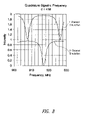
- FIG. 8 is a plot of I and Q output strength at a distance of 4 meters.
- FIG. 9 is a plot of I and Q output strength at a distance of 8 meters.
- FIG. 10 is a plot of calculated null spacing in frequency with respect to distance.
- FIG. 11 is a plot of in-phase signal strength for a tag 1.8 meters from an antenna and with a 20-foot cable.
- FIG. 12 is a plot of null spacing with respect to distance for the tag of FIG. 11 .
- FIG. 13 is a plot of I and Q signals in response to a masked scroll command.
- FIG. 14 is a plot of the phase angle relationships of the I and Q signals.
- FIG. 15 is a plot of the phase angle rotation/MHz with respect to distance.
- an embodiment of the present invention is directed to an RF communication system 34 that determines a distance between a reader or interrogator 36 and an RF transponder or tag 38 .
- the system 34 determines the distance by transmitting from the interrogator 36 to the RF tag 38 a first signal 40 at a first frequency and a frequency modulated second signal 42 at a second frequency.
- the RF tag 38 compares the signals 40 , 42 and determines a phase difference between the two signals.
- the distance between the interrogator 36 and the RF tag 38 is directly related to that detected phase difference.
- the interrogator 36 includes a controller 44 , a variable signal source 46 , a tapped transmission line 48 , a signal analyzer 50 , and an antenna 52 .
- the controller 44 can be any general purpose processor, such as a known microprocessor, or can be specifically designed to control the operation of the interrogator 36 as described herein. Examples of the tapped transmission line 48 and signal analyzer 50 can be found in U.S. Pat. No. 4,360,810 to Landt, which is incorporated by reference herein in its entirety.
- the tapped transmission line 48 enables the single antenna 52 to be used to transmit and receive signals simultaneously. Of course other systems for receiving and decoding the response signal from the RF tag 38 could be employed, such as the system shown in U.S. Pat. No. 4,075,632, which is incorporated herein by reference.
- the RF tag 38 includes a controller 54 , a memory 56 , a modulating switch 58 , an antenna 60 , a phase comparison circuit 62 , and a mode switch 64 .
- the controller 54 can be any general purpose processor, such as a known microprocessor, programmed to control the operation of the RF tag 38 as described herein or can be specifically designed to provide the control functions.
- the mode switch 64 alternately couples the antenna 60 to either the modulating switch 58 or the phase comparison circuit 62 under the control of the controller 54 as discussed in more detail below.
- an information code such as an identification code that identifies the RF tag 38 or an object to which the RF tag is attached or both.
- the information code could represent numerous other pieces of information, such as the environmental conditions surrounding the RF tag 38 , inventory information associated with the RF tag, or information that was previously written to the RF tag before or after the RF tag was placed into service.
- the memory 56 can be implemented with any type of memory, but preferably is non-volatile memory so that the information code is not lost when power is lost.
- the interrogator 36 transmits a continuous wave interrogation signal to the RF tag 38 in an attempt to determine the identity of the RF tag.
- the controller 54 of the RF tag 38 creates a modulating signal that is applied to the modulating switch 58 , which modulates the interrogation signal to produce a backscatter response signal that is transmitted back to the interrogator 36 .
- the modulation of the interrogation signal can be amplitude-modulation as described above with respect to FIG. 1 or can be phase-modulation as described in U.S. patent application Ser. No. 09/588,997 entitled Phase Modulation in RF Tag, which was abandoned in favor or U.S. patent application Ser. No. 10/928,712 entitled Phase Modulation in RF Tag, which are incorporated herein by reference.
- the response signal from the RF tag 38 is received by the interrogator 38 and mixed with the interrogation signal in the tapped transmission line 48 .
- the tapped transmission line 48 and signal analyzer 50 combine to demodulate the response signal to determine the information code of the RF tag 38 and pass the information code to the controller 44 .
- the controller 44 determines whether the information code is valid, and if so, transmits an acknowledgement signal to the RF tag 38 .
- the RF tag 38 switches into a distance determination mode by coupling the phase comparison circuit 62 to the antenna 60 via the mode switch 64 .
- the interrogator 36 transmits the first and second signals 40 , 42 to the RF tag 38 .
- the second signal 42 is transmitted after the first signal 40 is transmitted, but the signals could be transmitted simultaneously by separate antennas without departing from the invention.
- the controller 44 of the interrogator 36 can be programmed to cause the variable signal source 46 to transmit only the first signal 40 at the first frequency followed by the second signal 42 at the second frequency.
- the controller 44 can be programmed to cause the signal source 46 to transmit a frequency ramp that starts at the first frequency and includes the second frequency, that is, the first and second signals 40 , 42 can be part of the frequency ramp.
- the signal source 46 can randomly or pseudo-randomly changes frequencies to transmit the first and second signals 40 , 42 .
- the invention includes any combination of two or more frequencies.
- the phase comparison circuit 62 of the RF tag 38 compares the signals 40 , 42 and determines a phase difference between the two signals.
- the distance between the interrogator 36 and the RF tag 38 is directly related to that detected phase difference.
- the phase comparison circuit 62 passes to the controller 54 information indicative of the phase difference, which the controller can use to compute the distance between the interrogator 36 and the RF tag 38 .
- the phase comparison circuit 62 includes a signal divider 66 , phased lock loop 68 , mixer 70 , and null/peak counter 72 .
- the signal divider 66 divides the incoming first signal 40 into two identical signals, one of which going to the phase lock loop 68 .
- the phase lock loop 68 phase locks, and preferably amplitude locks, on the incoming signal to produce a reference signal that is substantially identical to the incoming first signal 40 .
- the phase lock loop 68 preferably is selected to provide a robust phase lock with a long lock and hold capability.
- the reference signal is passed to the mixer 70 , which also receives the other one of the signals from the signal divider 66 and produces a mixed output signal that is a combination of the two signals input to the mixer.
- the mixed output signal is a combination of the first signal 40 received from the signal divider 66 and the reference signal, which is substantially identical to the first signal 40 , so the mixed output signal is equal to the first signal 40 except with larger peaks and valleys.
- the mixer 70 receives at one input the second signal 42 from the signal divider 66 and at the other input the reference signal which is substantially identical to the first signal 40 .
- the mixer 70 combines the second signal 42 with the reference signal, resulting in a mixed output signal with two frequency components.
- the second signal 42 will be at a maximum while the reference signal is at a minimum, resulting in null points in the mixed output signal.
- Consecutive null points of the mixed output signal will be separated by peak points at which both the second and reference signals are at a maximum, or both are at a minimum.
- the null/peak counter 72 counts either the null points or the peak points in the mixed output signal and provides the resulting count to the controller 54 .
- the null/peak counter 70 can be either an analog counter or can include an analog/digital converter and a digital signal processor to determine the count digitally.
- the frequencies of the first and second signals 40 , 42 are known to the controller 54 , and thus, the controller uses the count provided by the null/peak counter 72 to compute the distance between the interrogator 36 and the RF tag 38 .
- the controller can incorporate the count into a count signal that is transmitted by the RF tag 38 back to the interrogator 36 .
- the controller 44 would then use the count and the frequencies of the first and second signals 40 , 42 to determine the distance between the interrogator 36 and the RF tag 38 .
- a first signal at 880 MHz has a wavelength of 34.0909091 cm and a second signal at 884 MHz has a wavelength of 33.9366516 cm.
- the first and second signals will be 180 degrees out of phase, resulting in a null point in the mixed signal output by the mixer 70 .
- there will be an additional null point and thus, the distance between the interrogator 36 and the RF tag 38 can be determined with an accuracy of +/ ⁇ 37 m using a first signal at 880 MHz and a second signal at 884 MHz.
- the accuracy can be improved by using a frequency modulated second signal rather than keeping the second signal at only the second frequency.
- the second signal includes a first portion at 883 MHz, a second portion at 884 MHz, and a third portion at 890 MHz. Mixing each of those portions of the second signal with the first signal results in first, second, and the mixed signals with nulls at distances of 50, 37.5, and 15 meters, respectively. Therefore, if the counter counts 1 null for each of the first and second mixed signals and 3 nulls for the third mixed signal, then the controller can determine that the distance between the interrogator 36 and RF tag 38 is between 50 and 60 meters.
- the first mixed signal would have had no nulls; and if the distance were more than 60 meters, then the third mixed signal would have had 4 nulls.
- the accuracy of the distance determination can be improved further.
- the interrogator 36 employs a quarter-wave dipole antenna as the antenna 52 , but any type of antenna could be employed.
- the antenna 52 is a phased-array antenna, which enables the interrogator 36 to determine the direction of the RF tag 38 relative to the interrogator. By determining both the direction and distance of the RF tag 38 relative to the interrogator 36 , the interrogator accurately determines the location of the RF tag 38 .
- FIG. 4 Shown in FIG. 4 is an alternate interrogator 36 A that can determine the direction and distance of the RF tag 38 relative to the interrogator 36 A without employing a direction-determining antenna like the phased-array antenna. Instead, the interrogator 36 A employs first and second antennas 52 A, 52 B that are each connected by an antenna switch 74 to the same tapped transmission line 48 as in the interrogator 36 of FIG. 2 . To determine the location (distance and direction) of the RF tag 36 , the interrogator 36 A determines first and second distances from the first and second antennas 52 A, 52 B, respectively, to the RF tag according to the same scheme as described above.
- the interrogator 36 A first transmits the first and second signals via the first antenna 52 A, the RF tag 38 counts the nulls in the mixed signal output from the mixer 70 , and the controller 44 calculates the first distance; and then the process is repeated using the second antenna 52 A to determine the second distance.
- the controller 44 controls which antenna 52 A, 52 B is used at a time by controlling the antenna switch 74 .
- the controller 44 uses the first and second distances and the known distance between the two antennas 52 A, 52 B to compute the location of the RF tag 38 using simple geometry.
- FIG. 5 Shown in FIG. 5 is another alternate interrogator 36 B that can locate (distance and direction) the RF tag 38 or any prior art RF tag without modifications to the prior art RF tags.
- the interrogator 36 B includes, in addition to the same elements 44 - 52 of the interrogator 36 of FIG. 2 , a position input device 76 , and the null/peak counter 72 .
- the position input device 76 inputs to the controller 44 the positions of the interrogator 36 B at two different locations.
- the interrogator 36 B takes a distance measurement to the RF tag at each of the two different locations of the interrogator and uses those distance measurements, together with the position information provided by the position input device 76 , to compute the location of the RF tag.
- the position input device can be a simple keyboard or other device through which a user inputs the position of the interrogator or it can be an accelerometer or other device that measures a position change from a first location to a second location of the interrogator.
- the interrogator 36 B can be moved between two locations for which position information is pre-programmed into the controller 44 to avoid having to input new position information with each distance determination.
- the interrogator 36 B can determine the location of any RF tag.
- the controller 44 causes the variable signal source 46 to transmit the first and second signals 40 , 42 via the antenna 52 .
- the RF tag reflects and modulates the first and second signals 40 , 42 .
- the modulation is done to distinguish the RF tag from other objects such as metal cans or other reflecting objects.
- the reflected first signal 40 is received by the antenna 52 and mixed with the second signal 42 by the tapped transmission line 48 .
- the null/peak counter 72 counts the nulls or peaks in the mixed signal output by the tapped transmission line 48 and the controller 44 determines a first distance between the interrogator 36 B and the RF tag based on the null or peak count. It should be appreciated that the distance determination algorithm used by the controller must compensate for the fact that the total path length of the communication is now out and back.
- the user then moves the interrogator 36 B to a second location and the process is repeated to determine a second distance between the interrogator 36 B and the RF tag.
- the controller 44 determines the location of the RF tag based on the first and second distances and on the interrogator location information provided by the position input device 76 .
- the interrogator 36 B like the interrogators 36 , 36 A, can be provided as a hand-held device.
- FIGS. 2-5 show the interrogators 36 , 36 A, 36 B incorporating the variable signal source 46 , it should be appreciated that the roles of the interrogator and the RF tag can be completely reversed. That is, the RF tag could transmit the first and second signals to the interrogator, and either the interrogator or the RF tag could perform any of the distance determination functions. In may be preferable to incorporate many or all of the distance determination functions on the interrogator to keep the size of the RF tag to a minimum, but it is not essential to the invention.
- a multi-channel interrogator or receiver can be used where the phase information between multiple channels can be used with two or more successive readings in time or in frequency or in relative distance to determine a real distance or a position or location, or a relative movement of a tag or any combination of the foregoing.
- the system can be used to determine if a multi-path null has occurred to decide to use or not to use this information when determining distance by other means.
- other information can be used such as a null in either direction, field strength estimation, backscater intensity, and ramping power to determine relative distance.
- two or more successive readings in time or frequency or relative distance can be made of the phase information on multiple channels to determine the relative field in front of a reader antenna by having a tag of known position modulate or having an antenna of known position modulate.
- a combination of the above is also provided where a tag is powered in the standard UHF fashion at a single frequency at a time and where a lower power signal that is spread spectrum in nature or UWB is used to take a near-instantaneous snapshot of the data showing quadrature nulls.
- the plot so taken can contain much if not all of the data for determining distance or position or delta in relation to the standard ranging position using quadrature nulls.
- the detected backscatter modulation intensity from an RFID transponder is determined by a number of factors, including, but not limited to, transmitted power by the interrogator, antenna gain (both interrogator and transponder), relative antenna orientation, distance between the transponder and the interrogator, frequency, and the receiver design.
- multi-channel receiver architectures are used for range and bearing determination between an RFID interrogator and a selected transponder or closely spaced group of transponders.
- FIG. 6 shown therein is a simplified block diagram of a homodyne receiver 82 in which an incoming RF signal is received on an antenna 84 and processed by a bandpass filter 86 .
- the filtered signal then passes through a low noise amplifier 88 and is combined with the output of a local oscillator 92 at a mixer 90 .
- a lowpass filter 94 receives the output from the mixer 90 where the resulting base band signal is filtered to select a desired channel on the output 96 .
- the main advantage of a homodyne receiver is that the incoming RF signal is down-converted directly to base band without any intermediate frequency stage. As a result, this architecture is simple and does not require any high-frequency bandpass filter, thus requiring fewer components, especially external components.
- a homodyne receiver uses two mixers as shown more clearly in FIG. 7 .
- a local oscillator 98 is shown generating a first output received at a first mixer 100 , which also receives as input the RF signal 102 .
- the output from the local oscillator 98 also passes through a 90-degree phase shifter 104 , the output of which is fed to a second mixer 106 that also receives the RF input 102 .
- the output from the first mixer denoted in FIG. 7 as the “I mixer,” is the in-phase I output 108
- the output 110 from the “Q mixer” 106 is quadrature or Q output 110 that is 90 degrees out of phase from the I output 108 .
- the received signal 102 is split and fed into both mixers.
- the RF signal drives the first mixer 100 to generate the in-phase output 108 and the RF signal 102 drives the “Q mixer” 106 to generate the 90-degree out-of-phase Q output 110
- the amplitude will drop to zero when the phase angle is 90 degrees plus a multiple of pi radians of the signal because a cosine of those angles is equal to zero.
- the Q output 110 the amplitude falls to zero whenever the phase angle is a multiple of pi because the Q output 110 is merely the I output 108 shifted by 90 degrees.
- these outputs are combined or summed, their outputs will have periods of signal cancellation or quadrature nulls. Movement of the device sending the RF signal, such as an RFID transponder, can change the relationship of these signals and hence the intensity, duration, and frequency of the nulls.
- Airy function for a Fabry-Perot etalon can be modified to describe quadrature backscatter amplitude by subtracting the normal expression for cavity transmission from one and appropriately scaling the phase rotation.
- the reflectivity term (R) is related to the antenna gains of the tag and transceiver as well as the signal strength and amplifier characteristics:
- R The Reflectivity of the Mirrors used in the Fabry-Perot Etalon. As applied to backscatter modulation, this term is related to Antenna Gains for the Reader and the Tag, Amplifier Characteristics.
- phi an angular term used in the expression that is a function of distance, wavelength and the angular dispersion of the beam (expression given in the text).
- the phase change is a function of distance, wavelength and the dispersion of the beam.
- n the refractive index of the transmission medium.
- Nulls in this expression occur at periodic frequencies. Null spacing follows the modified expression for an etalon's free spectral range:
- predicted I/Q signal strength as a function of frequency is shown in FIGS. 8 and 9 for distances of 4 and 8 meters respectively.
- the null spacing in MHz and calculated distance is shown in FIG. 10 .
- the distance d can be determined from the null spacing via the free spectral range equation above.
- the null spacing is a function of the distance to the tag.
- FIG. 11 Shown in FIG. 11 is a plot for a tag 1.8 meters from an antenna with a 20-foot cable.
- the observed null spacing is substantially closer than that predicted by a 1.8 Meter spacing.
- the effective distance to the tag is on the order of 13 meters.
- FIG. 13 illustrates an example of the base band in-phase (I) and quadrature (Q) signal from a portion of a tag response to a “masked scroll” command.
- the channels are in fair relative phase with each other. At various times each will be inverted with respect to each other. As each of these signals pass through quadrature nulls, either through motion at a fixed frequency or through a frequency change at a fixed distance, the amplitude of the voltage passes through zero.
- the 90-degree delay in the homodyne receiver design ensures that as one channel passes through a null, the other channel is at maximum signal intensity. The sense of this signal inverts every quarter wavelength. An important aspect of this is the characteristic inversion of the data that occurs after the quadrature null and the relative phase before and after in relation to the other channel.
- FIG. 14 which is a plot of the I data against the Q data from FIG. 12 , shows a vector with a characteristic phase angle. As frequency or distance changes, this vector rotates. The direction of the rotation is determined by whether the frequency is increasing or decreasing or if the direction of travel is towards or away from the antenna.
- the magnitude of the rotation is calculated from the expression for free spectral range as discussed above. A given channel passes through a minimum for every 180 degrees of rotation of the I/Q vector. The magnitude of this rotation as a function of frequency change,
- the distance can be measured by comparing the angles of the I-Q vectors at two frequencies.
- the rotation of the I-Q vector could be used to find the distance to a tag very quickly.
- a common data rate available under U.S. regulations commands to takes can take less than 2 msec to execute.
- To find the approximate distance to the tag one could move to a frequency, issue a command that causes a tag response, move to another frequency, issue another similar command that causes another tag response, and compare the change in I-Q phase angle. This could take about 10 msec to complete with certain frequency hopping schemes.
- the present invention discloses a method of determining a positional relationship between a radio frequency signal source and a multi-channel receiver, comprising: receiving at the multi-channel receiver a first signal from the signal source that is at a first frequency; issuing a first global scroll command to obtain a first I-Q signal vector; receiving at the multi-channel receiver a second signal from the signal source that is at a second frequency; issuing a second global scroll command to obtain a second I-Q signal vector; and comparing the first and second I-Q vectors and calculating the positional relationship distance between the signal source and the multi-channel receiver.
- issuing the first and second global scroll commands comprises issuing a masked scroll command.
- phase changes can be made in firmware in the receiver microprocessor that acquires data from the tag and controls the interrogation signal frequency. By evaluating the phase null behavior on the I and Q Channels or by examining the way the phase angle rotates as frequency is changed, the microprocessor in the reader can determine distance as described above.
- the RF communication systems and methods discussed herein provide important advantages over prior systems.
- the disclosed RF communication systems greatly extend the range of applications to which RF tag technology can be applied.
- the RF communication system discussed above can be employed to locate lost weapons on a battlefield, animals across a large property, and any inventory object within a warehouse.
Abstract
Description
where:
where:
where:
is a linear function of distance, as shown in
-
- a) An RFID system with a multi-channel receiver where the phase information relative between the multiple channels can be used with two or more successive readings in time or in frequency or in relative distance to determine real distance to the tag.
- b) An RFID system with a multi-channel receiver where the phase information relative between the multiple channels can be used with two or more successive readings in time or in frequency or in relative distance to determine position of the tag by using antenna vectoring, multiple antennas or characteristics of an antenna pattern.
- c) An RFID system with a multi-channel receiver where the phase information relative between the multiple channels can be used with two or more successive readings in time or in frequency or in relative distance to determine the vector to the tag by using antenna vectoring, multiple antennas or characteristics of an antenna pattern.
- d) An RFID system with a multi-channel receiver where the phase information relative between the multiple channels can be used with two or more successive readings in time or in frequency or in relative distance to determine if the tag is coming toward or away from the antenna.
- e) An RFID system with a multi-channel receiver where the phase information relative between the multiple channels can be used with two or more successive readings in time or in frequency or in relative distance to determine if a multi-path null has occurred to decide to use or not use this information when determine distance by other means.
- f) An RFID system with a multi-channel receiver where the phase information relative between the multiple channels can be used with two or more successive readings in time or in frequency or in relative distance to determine position of the tag and using this relative phase information in conjunction with other information such as null in either direction, field strength estimation, backscatter intensity, and ramping power to the tag to determine relative distance.
- g) An RFID system with a multi-channel receiver where the phase information relative between the multiple channels can be used with two or more successive readings in time or in frequency or in relative distance to determine the relative field in front of a reader antenna by having a tag of known position modulate or having an antenna of known position modulate.
- h) A combination of the above where a tag is powered in the standard UHF fashion at a single frequency at a time and where a lower power signal which is spread spectrum in nature or UWB is used to take a near instantaneous snapshot of the data showing quadrature nulls. The plot so taken contains much if not all of the data for determining distance or position or delta in both related to the standard ranging position using quadrature nulls.
Claims (26)
Priority Applications (3)
| Application Number | Priority Date | Filing Date | Title |
|---|---|---|---|
| US11/080,379 US7580378B2 (en) | 2000-06-06 | 2005-03-14 | Distance/ranging determination using relative phase data |
| PCT/US2006/008611 WO2006099148A1 (en) | 2005-03-14 | 2006-03-10 | Distance/ranging determination using relative phase data |
| EP06748335A EP1869493A1 (en) | 2005-03-14 | 2006-03-10 | Distance/ranging determination using relative phase data |
Applications Claiming Priority (2)
| Application Number | Priority Date | Filing Date | Title |
|---|---|---|---|
| US09/588,998 US6868073B1 (en) | 2000-06-06 | 2000-06-06 | Distance/ranging by determination of RF phase delta |
| US11/080,379 US7580378B2 (en) | 2000-06-06 | 2005-03-14 | Distance/ranging determination using relative phase data |
Related Parent Applications (1)
| Application Number | Title | Priority Date | Filing Date |
|---|---|---|---|
| US09/588,998 Continuation-In-Part US6868073B1 (en) | 2000-06-06 | 2000-06-06 | Distance/ranging by determination of RF phase delta |
Publications (2)
| Publication Number | Publication Date |
|---|---|
| US20050237953A1 US20050237953A1 (en) | 2005-10-27 |
| US7580378B2 true US7580378B2 (en) | 2009-08-25 |
Family
ID=36602691
Family Applications (1)
| Application Number | Title | Priority Date | Filing Date |
|---|---|---|---|
| US11/080,379 Expired - Lifetime US7580378B2 (en) | 2000-06-06 | 2005-03-14 | Distance/ranging determination using relative phase data |
Country Status (3)
| Country | Link |
|---|---|
| US (1) | US7580378B2 (en) |
| EP (1) | EP1869493A1 (en) |
| WO (1) | WO2006099148A1 (en) |
Cited By (35)
| Publication number | Priority date | Publication date | Assignee | Title |
|---|---|---|---|---|
| US20070103303A1 (en) * | 2005-11-07 | 2007-05-10 | Radiofy Llc, A California Limited Liability Company | Wireless RFID networking systems and methods |
| US20080143584A1 (en) * | 2006-12-18 | 2008-06-19 | Radiofy Llc, A California Limited Liability Company | Method and system for determining the distance between an RFID reader and an RFID tag using phase |
| US20080143482A1 (en) * | 2006-12-18 | 2008-06-19 | Radiofy Llc, A California Limited Liability Company | RFID location systems and methods |
| US20090002165A1 (en) * | 2007-06-28 | 2009-01-01 | Micron Technology, Inc. | Method and system of determining a location characteristic of a rfid tag |
| US20090303004A1 (en) * | 2008-06-05 | 2009-12-10 | Keystone Technology Solutions, Llc | Systems and Methods to Determine Motion Parameters using RFID Tags |
| US20090303005A1 (en) * | 2008-06-05 | 2009-12-10 | Keystone Technology Solutions, Llc | Systems and Methods to Determine Kinematical Parameters using RFID Tags |
| US20100182133A1 (en) * | 2007-06-28 | 2010-07-22 | The Nippon Signal Co., Ltd. | Reader/writer and article sorting system |
| US20100271263A1 (en) * | 2008-03-31 | 2010-10-28 | Mehran Moshfeghi | Method and System for Determining the Position of a Mobile Station |
| US20100309051A1 (en) * | 2008-03-31 | 2010-12-09 | Mehran Moshfeghi | Method and system for determining the position of a mobile device |
| US20110043407A1 (en) * | 2008-03-31 | 2011-02-24 | GOLBA Radiofy LLC, a California Limited Liability Company | Methods and systems for determining the location of an electronic device |
| US7911324B2 (en) | 2001-02-16 | 2011-03-22 | Automotive Technologies International, Inc. | Method and system for obtaining information about RFID-equipped objects |
| US20110090062A1 (en) * | 2009-10-16 | 2011-04-21 | Rf Controls, Llc | Phase Ranging RFID Location System |
| US20110187600A1 (en) * | 2010-01-29 | 2011-08-04 | Tc License Ltd. | System and method for measurement of distance to a tag by a modulated backscatter rfid reader |
| US8149155B2 (en) | 2007-12-18 | 2012-04-03 | Omron Corporation | Range measuring method, range measuring apparatus, non-contacted IC medium and range measuring system |
| US8169312B2 (en) | 2009-01-09 | 2012-05-01 | Sirit Inc. | Determining speeds of radio frequency tags |
| US20120182129A1 (en) * | 2008-06-06 | 2012-07-19 | Lyngsoe Systems | System and method for wireless communications |
| US8226003B2 (en) | 2006-04-27 | 2012-07-24 | Sirit Inc. | Adjusting parameters associated with leakage signals |
| US8248212B2 (en) | 2007-05-24 | 2012-08-21 | Sirit Inc. | Pipelining processes in a RF reader |
| US20120280862A1 (en) * | 2011-05-03 | 2012-11-08 | Harris Corporation | Wireless location detection and/or tracking device and associated methods |
| US8416079B2 (en) | 2009-06-02 | 2013-04-09 | 3M Innovative Properties Company | Switching radio frequency identification (RFID) tags |
| US8427316B2 (en) | 2008-03-20 | 2013-04-23 | 3M Innovative Properties Company | Detecting tampered with radio frequency identification tags |
| US8446256B2 (en) | 2008-05-19 | 2013-05-21 | Sirit Technologies Inc. | Multiplexing radio frequency signals |
| US8742975B2 (en) | 2010-04-27 | 2014-06-03 | Amtech Systems, LLC | System and method for microwave ranging to a target in presence of clutter and multi-path effects |
| US9116237B2 (en) | 2013-01-01 | 2015-08-25 | Disney Enterprises | Phase-based ranging for backscatter RFID tags |
| US20170180011A1 (en) * | 2015-12-17 | 2017-06-22 | Humatics Corporation | Radio-frequency localization techniques and associated systems, devices, and methods |
| US9829560B2 (en) | 2008-03-31 | 2017-11-28 | Golba Llc | Determining the position of a mobile device using the characteristics of received signals and a reference database |
| US10062025B2 (en) | 2012-03-09 | 2018-08-28 | Neology, Inc. | Switchable RFID tag |
| WO2018191312A1 (en) | 2017-04-11 | 2018-10-18 | Dolby Laboratories Licensing Corporation | Layered augmented entertainment experiences |
| US10139484B2 (en) * | 2014-08-14 | 2018-11-27 | Samsung Electronics Co., Ltd. | Apparatus and method for wireless distance measurement |
| WO2018229681A1 (en) | 2017-06-14 | 2018-12-20 | Drb S.R.L.S. | Radio beacon system |
| US10422870B2 (en) | 2015-06-15 | 2019-09-24 | Humatics Corporation | High precision time of flight measurement system for industrial automation |
| US10571558B2 (en) | 2008-06-05 | 2020-02-25 | Micron Technology, Inc. | Systems and methods to use radar in RFID systems |
| US10591592B2 (en) | 2015-06-15 | 2020-03-17 | Humatics Corporation | High-precision time of flight measurement systems |
| US10976419B2 (en) * | 2017-03-17 | 2021-04-13 | Kabushiki Kaisha Toshiba | Distance measuring device and distance measuring method |
| US20230033590A1 (en) * | 2021-07-30 | 2023-02-02 | Toshiba Global Commerce Solutions Holdings Corporation | Radio frequency identification discontinuity correction |
Families Citing this family (63)
| Publication number | Priority date | Publication date | Assignee | Title |
|---|---|---|---|---|
| US7228228B2 (en) * | 2000-11-15 | 2007-06-05 | Sagentia Limited | Tag tracking |
| WO2004114240A2 (en) * | 2003-06-13 | 2004-12-29 | Xtec, Incorporated | Differential radio frequency identification reader |
| US7058377B1 (en) * | 2003-08-14 | 2006-06-06 | The United States Of America As Represented By The Secretary Of The Navy | Dual channel downconverter for pulsed radio frequency measurements |
| DE102004006504A1 (en) * | 2004-02-10 | 2005-09-08 | Infineon Technologies Ag | Contactless data carrier with signal generator |
| US7616092B2 (en) * | 2004-05-11 | 2009-11-10 | Sensormatic Electronics Corporation | Wireless transponder for a security system |
| DE102005009579B4 (en) * | 2005-02-28 | 2010-04-22 | ASTRA Gesellschaft für Asset Management mbH & Co. KG | Method for locating a detector wafer |
| US7649491B2 (en) * | 2005-03-09 | 2010-01-19 | Omron Corporation | Distance measuring apparatus, distance measuring method, reflector and communication system |
| US20060220795A1 (en) * | 2005-03-22 | 2006-10-05 | Supply Focus | Method and apparatus for tag with adjustable read distance |
| US8191780B2 (en) | 2005-04-07 | 2012-06-05 | Freedom Shopping, Inc. | Self checkout kiosk and retail security system |
| US7405662B2 (en) * | 2005-06-14 | 2008-07-29 | Datalogic Mobile, Inc. | Wireless tag ranging |
| US20070096876A1 (en) * | 2005-10-20 | 2007-05-03 | Raj Bridgelall | Adaptive RFID devices |
| WO2007083889A1 (en) * | 2005-12-15 | 2007-07-26 | Electronics And Telecommunications Research Institute | Method and apparatus for transmitter locating using a single receiver |
| KR100904681B1 (en) * | 2005-12-15 | 2009-06-25 | 한국전자통신연구원 | Method and apparatus for transmitter locating using a single receiver |
| FI119453B (en) * | 2006-01-30 | 2008-11-14 | Voyantic Oy | Apparatus and method for radio frequency systems |
| US7652577B1 (en) | 2006-02-04 | 2010-01-26 | Checkpoint Systems, Inc. | Systems and methods of beamforming in radio frequency identification applications |
| DE102006026495A1 (en) * | 2006-06-07 | 2007-12-13 | Fraunhofer-Gesellschaft zur Förderung der angewandten Forschung e.V. | Transponder`s position or location determining method for use in e.g. radio frequency identification system, involves determining mapping signals, and assigning inductive coupling to antenna device by distance or orientation of transponder |
| US7873326B2 (en) | 2006-07-11 | 2011-01-18 | Mojix, Inc. | RFID beam forming system |
| US20080084312A1 (en) * | 2006-10-10 | 2008-04-10 | Daily Michael A | Radio frequency identification layered foam tag |
| US7880618B2 (en) * | 2007-03-28 | 2011-02-01 | Round Rock Research, Llc | Methods and systems of determining physical characteristics associated with objects tagged with RFID tags |
| US7859408B2 (en) * | 2007-03-28 | 2010-12-28 | Round Rock Research, Llc | Methods and systems of determining physical characteristics associated with objects tagged with RFID tags |
| US8181865B2 (en) * | 2007-04-24 | 2012-05-22 | Freedom Shopping, Inc. | Radio frequency identification point of sale unassisted retail transaction and digital media kiosk |
| US20080280560A1 (en) * | 2007-05-09 | 2008-11-13 | Micron Technology, Inc. | Method and system of placing a rfid tag in a continuous transmission mode |
| US7932814B2 (en) * | 2007-10-04 | 2011-04-26 | Round Rock Research, Llc | Method and system to determine physical parameters as between a RFID tag and a reader |
| US7944356B2 (en) * | 2007-10-04 | 2011-05-17 | Round Rock Research, Llc | Method and system to determine physical parameters as between an RFID tag and a reader |
| DE102007060810A1 (en) * | 2007-12-18 | 2009-06-25 | Maquet Gmbh & Co. Kg | Arrangement, system and method for the wireless control of a device |
| US20090160638A1 (en) * | 2007-12-20 | 2009-06-25 | 3M Innovative Properties Company | Radio frequency identification reader system |
| US7884753B2 (en) * | 2008-02-04 | 2011-02-08 | Honeywell International Inc. | Apparatus and method for ranging of a wireless transceiver with a switching antenna |
| US20090201134A1 (en) * | 2008-02-08 | 2009-08-13 | Broadcom Corporation | Rfid with phase rotated backscattering and methods for use therewith |
| US9007178B2 (en) | 2008-02-14 | 2015-04-14 | Intermec Ip Corp. | Utilization of motion and spatial identification in RFID systems |
| US8994504B1 (en) * | 2008-02-14 | 2015-03-31 | Intermec Ip Corp. | Utilization of motion and spatial identification in mobile RFID interrogator |
| US9262912B2 (en) * | 2008-02-25 | 2016-02-16 | Checkpoint Systems, Inc. | Localizing tagged assets using modulated backscatter |
| EP2420958B1 (en) | 2008-04-07 | 2016-10-19 | Ruizhang Technology Limited Company | Voltage multiplier powering RFID tags |
| EP3232414A1 (en) | 2008-04-14 | 2017-10-18 | Mojix, Inc. | Radio frequency identification tag location estimation and tracking system |
| CN102077115A (en) * | 2008-07-02 | 2011-05-25 | Nxp股份有限公司 | A system for reading information transmitted from a transponder |
| DE102008050764A1 (en) * | 2008-10-09 | 2010-04-22 | Siemens Aktiengesellschaft | Method and device for increasing the stopping accuracy of a moving object |
| US8279112B2 (en) * | 2008-11-03 | 2012-10-02 | Trimble Navigation Limited | Methods and apparatuses for RFID tag range determination |
| DE102009060591A1 (en) * | 2008-12-30 | 2010-07-08 | Atmel Automotive Gmbh | Transmitter-receiver circuit and method for distance measurement between a first node and a second node of a radio network |
| DE102009060593A1 (en) * | 2008-12-30 | 2010-07-08 | Atmel Automotive Gmbh | System, method and circuit for distance measurement between two nodes of a radio network |
| US8339243B2 (en) * | 2008-12-31 | 2012-12-25 | Mitac Technology Corp. | System and method for positioning active RFID tag |
| WO2011054128A1 (en) * | 2009-11-03 | 2011-05-12 | 北京简约纳电子有限公司 | Device and method for precisely measuring near-field communication distance of radio frequency identification (rfid) tag |
| US20110221633A1 (en) * | 2010-03-11 | 2011-09-15 | Benjamin Bela Schramm | Methods and systems for determining the distance between two objects using wirelessly transmitted pulses |
| WO2011130582A1 (en) | 2010-04-14 | 2011-10-20 | Mojix, Inc. | Systems and methods for detecting patterns in spatio-temporal data collected using an rfid system |
| GB201006904D0 (en) | 2010-04-26 | 2010-06-09 | Cambridge Entpr Ltd | RFID TAG location systems |
| US8588696B2 (en) * | 2010-06-04 | 2013-11-19 | Apple Inc. | Adaptive cellular power control |
| US8929494B2 (en) | 2010-11-30 | 2015-01-06 | Mojix, Inc. | Systems and methods for joint beamforming and preamble detection |
| KR20120074495A (en) * | 2010-12-28 | 2012-07-06 | 한국전자통신연구원 | Radio frequency identification tag |
| US9208365B2 (en) * | 2011-01-12 | 2015-12-08 | Intermec Ip Corp. | Method and apparatus to mitigate multipath in RFID |
| ITMI20111017A1 (en) * | 2011-06-07 | 2012-12-08 | Univ Pisa | METHOD OF LOCALIZATION OF AN EMITTER ELEMENT OF AN ELECTROMAGNETIC SIGNAL |
| US9176215B2 (en) * | 2012-03-22 | 2015-11-03 | Intermec Ip Corp. | Synthetic aperture RFID handheld with tag location capability |
| US20130296747A1 (en) * | 2012-05-03 | 2013-11-07 | Physio-Control, Inc. | Rfid-based determination of compression and motion during cpr chest compression |
| US9111156B2 (en) | 2013-03-15 | 2015-08-18 | Mojix, Inc. | Systems and methods for compressive sensing ranging evaluation |
| US9883337B2 (en) | 2015-04-24 | 2018-01-30 | Mijix, Inc. | Location based services for RFID and sensor networks |
| EP3171291B8 (en) * | 2015-11-20 | 2019-02-20 | pro-micron GmbH | Method and inquiring device for requesting data from a passive element |
| US11079484B2 (en) * | 2016-06-22 | 2021-08-03 | Apple Inc. | Communication device and a method for localization |
| US10989788B2 (en) | 2016-11-17 | 2021-04-27 | Lion Group, Inc. | Radio frequency identification (RFID) system for determining location |
| KR102129440B1 (en) * | 2017-11-29 | 2020-07-08 | 주식회사 후본 | Communication device based on flexible circuit board |
| US10962632B2 (en) * | 2017-12-18 | 2021-03-30 | Texas Instruments Incorporated | Electronic device and method for low power RF ranging |
| CN107968673B (en) * | 2017-12-19 | 2021-06-18 | 候本株式会社 | Communication device based on flexible circuit board |
| US11126905B2 (en) * | 2018-11-16 | 2021-09-21 | Georgia Tech Research Corporation | Antenna-less RFID tag |
| JP7297619B2 (en) * | 2019-09-18 | 2023-06-26 | 株式会社東芝 | rangefinder |
| CN113109800A (en) * | 2019-12-24 | 2021-07-13 | 财团法人金属工业研究发展中心 | Radio frequency positioning method for measuring position of transceiver |
| CN113466840B (en) * | 2020-03-30 | 2022-09-20 | 阿里巴巴集团控股有限公司 | Distance measurement method, positioning method, device, equipment and system |
| CN116068490A (en) * | 2021-11-02 | 2023-05-05 | 华为技术有限公司 | Distance measurement method and device |
Citations (18)
| Publication number | Priority date | Publication date | Assignee | Title |
|---|---|---|---|---|
| US3098971A (en) | 1961-09-26 | 1963-07-23 | Robert M Richardson | Remotely actuated radio frequency powered devices |
| US3299424A (en) | 1965-05-07 | 1967-01-17 | Jorgen P Vinding | Interrogator-responder identification system |
| US4075632A (en) | 1974-08-27 | 1978-02-21 | The United States Of America As Represented By The United States Department Of Energy | Interrogation, and detection system |
| US4087816A (en) | 1975-12-19 | 1978-05-02 | Canadian Patents & Development Limited | VLF radio position location system |
| US4283726A (en) * | 1978-09-05 | 1981-08-11 | Lewis C. Spence | Dual frequency distance measuring system |
| US4360810A (en) | 1981-01-19 | 1982-11-23 | The United States Of America As Represented By The United States Department Of Energy | Multichannel homodyne receiver |
| US4728955A (en) | 1984-07-04 | 1988-03-01 | Stiftelsen Institutet For Mikrovagsteknik Vid Tekniska Hogskolan I Stockholm | Method for position-finding and apparatus herefor |
| US4851851A (en) | 1985-12-12 | 1989-07-25 | Stiftelsen Institutet For Mikrovagsteknik Vid Tekniska Hogskolan I Stockholm | Method for measuring the distance and/or the relative velocity between two objects |
| US5298904A (en) | 1992-08-04 | 1994-03-29 | Olich Kirk J | Distance measuring system |
| US5510795A (en) | 1994-11-10 | 1996-04-23 | Amtech Corporation | Single antenna location and direction finding system |
| US5528232A (en) | 1990-06-15 | 1996-06-18 | Savi Technology, Inc. | Method and apparatus for locating items |
| EP0851239A1 (en) | 1996-12-31 | 1998-07-01 | Lucent Technologies Inc. | Radio communication system with tag location facility |
| US5790022A (en) | 1996-09-09 | 1998-08-04 | Delvecchio; George | Security tracking system |
| US6084512A (en) | 1998-10-02 | 2000-07-04 | Lucent Technologies, Inc. | Method and apparatus for electronic labeling and localizing |
| WO2001095240A2 (en) | 2000-06-05 | 2001-12-13 | Transcore Holdings, Inc. | Method and apparatus to determine the direction to a transponder in a modulated backscatter communication system |
| WO2001094974A2 (en) | 2000-06-06 | 2001-12-13 | Battelle Memorial Institute | Distance/ranging by determination of rf phase delta |
| US6501807B1 (en) | 1998-02-06 | 2002-12-31 | Intermec Ip Corp. | Data recovery system for radio frequency identification interrogator |
| US20040196177A1 (en) | 2002-11-19 | 2004-10-07 | Radatec, Inc. | Method and system for calibration of a phase-based sensing system |
Family Cites Families (1)
| Publication number | Priority date | Publication date | Assignee | Title |
|---|---|---|---|---|
| US6686830B1 (en) * | 2000-06-28 | 2004-02-03 | Applied Wireless Identifications Group | Homodyne I/Q transceiver for a spread spectrum reader |
-
2005
- 2005-03-14 US US11/080,379 patent/US7580378B2/en not_active Expired - Lifetime
-
2006
- 2006-03-10 EP EP06748335A patent/EP1869493A1/en not_active Ceased
- 2006-03-10 WO PCT/US2006/008611 patent/WO2006099148A1/en active Application Filing
Patent Citations (19)
| Publication number | Priority date | Publication date | Assignee | Title |
|---|---|---|---|---|
| US3098971A (en) | 1961-09-26 | 1963-07-23 | Robert M Richardson | Remotely actuated radio frequency powered devices |
| US3299424A (en) | 1965-05-07 | 1967-01-17 | Jorgen P Vinding | Interrogator-responder identification system |
| US4075632A (en) | 1974-08-27 | 1978-02-21 | The United States Of America As Represented By The United States Department Of Energy | Interrogation, and detection system |
| US4087816A (en) | 1975-12-19 | 1978-05-02 | Canadian Patents & Development Limited | VLF radio position location system |
| US4283726A (en) * | 1978-09-05 | 1981-08-11 | Lewis C. Spence | Dual frequency distance measuring system |
| US4360810A (en) | 1981-01-19 | 1982-11-23 | The United States Of America As Represented By The United States Department Of Energy | Multichannel homodyne receiver |
| US4728955A (en) | 1984-07-04 | 1988-03-01 | Stiftelsen Institutet For Mikrovagsteknik Vid Tekniska Hogskolan I Stockholm | Method for position-finding and apparatus herefor |
| US4851851A (en) | 1985-12-12 | 1989-07-25 | Stiftelsen Institutet For Mikrovagsteknik Vid Tekniska Hogskolan I Stockholm | Method for measuring the distance and/or the relative velocity between two objects |
| US5528232A (en) | 1990-06-15 | 1996-06-18 | Savi Technology, Inc. | Method and apparatus for locating items |
| US5298904A (en) | 1992-08-04 | 1994-03-29 | Olich Kirk J | Distance measuring system |
| US5510795A (en) | 1994-11-10 | 1996-04-23 | Amtech Corporation | Single antenna location and direction finding system |
| US5790022A (en) | 1996-09-09 | 1998-08-04 | Delvecchio; George | Security tracking system |
| EP0851239A1 (en) | 1996-12-31 | 1998-07-01 | Lucent Technologies Inc. | Radio communication system with tag location facility |
| US6501807B1 (en) | 1998-02-06 | 2002-12-31 | Intermec Ip Corp. | Data recovery system for radio frequency identification interrogator |
| US6084512A (en) | 1998-10-02 | 2000-07-04 | Lucent Technologies, Inc. | Method and apparatus for electronic labeling and localizing |
| WO2001095240A2 (en) | 2000-06-05 | 2001-12-13 | Transcore Holdings, Inc. | Method and apparatus to determine the direction to a transponder in a modulated backscatter communication system |
| US20030058155A1 (en) | 2000-06-05 | 2003-03-27 | Landt Jeremy A. | Method and apparatus to determine the direction to a transponder in a modulated backscatter communication system |
| WO2001094974A2 (en) | 2000-06-06 | 2001-12-13 | Battelle Memorial Institute | Distance/ranging by determination of rf phase delta |
| US20040196177A1 (en) | 2002-11-19 | 2004-10-07 | Radatec, Inc. | Method and system for calibration of a phase-based sensing system |
Non-Patent Citations (3)
| Title |
|---|
| Notification Concerning Transmittal of International Preliminary Report on the Patentability (Chapter 1 of the Patent Cooperation Treaty) and Written Opinion of the International Searching Authority for PCT Application No. PCT US2006/008611, filed on Mar. 10, 2006, mailed Sep. 27, 2007, (11 pages). |
| Notification of Transmittal of the International Search Report and The Written Opinion of the International Searching Authority or the Declaration, PCT international Search Report, PCT Application No. PCT US2006/008611. Jul. 17, 2006 Mailed Nov. 11, 2005 (15 pages). |
| PCT Written Opinion of the International Searching Authority UPCT/US2006/008611 mailed Apr. 14, 2008 (total 9 pages). |
Cited By (94)
| Publication number | Priority date | Publication date | Assignee | Title |
|---|---|---|---|---|
| US7911324B2 (en) | 2001-02-16 | 2011-03-22 | Automotive Technologies International, Inc. | Method and system for obtaining information about RFID-equipped objects |
| US8345653B2 (en) | 2005-11-07 | 2013-01-01 | Radiofy Llc | Wireless RFID networking systems and methods |
| US8693455B2 (en) | 2005-11-07 | 2014-04-08 | Radiofy Llc | Wireless RFID networking systems and methods |
| US10037445B2 (en) | 2005-11-07 | 2018-07-31 | Radiofy Llc | Systems and methods for managing coverage area of wireless communication devices |
| US8107446B2 (en) | 2005-11-07 | 2012-01-31 | Radiofy Llc | Wireless RFID networking systems and methods |
| US20070103303A1 (en) * | 2005-11-07 | 2007-05-10 | Radiofy Llc, A California Limited Liability Company | Wireless RFID networking systems and methods |
| US8226003B2 (en) | 2006-04-27 | 2012-07-24 | Sirit Inc. | Adjusting parameters associated with leakage signals |
| US8294554B2 (en) | 2006-12-18 | 2012-10-23 | Radiofy Llc | RFID location systems and methods |
| US8754752B2 (en) | 2006-12-18 | 2014-06-17 | Radiofy Llc | RFID location systems and methods |
| US11009600B2 (en) | 2006-12-18 | 2021-05-18 | Innovo Surgical, Inc. | RFID location systems and methods |
| US11921192B2 (en) | 2006-12-18 | 2024-03-05 | Innovo Surgical, Inc. | RFID location systems and methods |
| US20080143482A1 (en) * | 2006-12-18 | 2008-06-19 | Radiofy Llc, A California Limited Liability Company | RFID location systems and methods |
| US20080143584A1 (en) * | 2006-12-18 | 2008-06-19 | Radiofy Llc, A California Limited Liability Company | Method and system for determining the distance between an RFID reader and an RFID tag using phase |
| US8248212B2 (en) | 2007-05-24 | 2012-08-21 | Sirit Inc. | Pipelining processes in a RF reader |
| US20100182133A1 (en) * | 2007-06-28 | 2010-07-22 | The Nippon Signal Co., Ltd. | Reader/writer and article sorting system |
| US20090002165A1 (en) * | 2007-06-28 | 2009-01-01 | Micron Technology, Inc. | Method and system of determining a location characteristic of a rfid tag |
| US9581689B2 (en) * | 2007-06-28 | 2017-02-28 | The Nippon Signal Co., Ltd. | Reader/writer and article sorting system |
| US8149155B2 (en) | 2007-12-18 | 2012-04-03 | Omron Corporation | Range measuring method, range measuring apparatus, non-contacted IC medium and range measuring system |
| US8427316B2 (en) | 2008-03-20 | 2013-04-23 | 3M Innovative Properties Company | Detecting tampered with radio frequency identification tags |
| US9829560B2 (en) | 2008-03-31 | 2017-11-28 | Golba Llc | Determining the position of a mobile device using the characteristics of received signals and a reference database |
| US9366745B2 (en) | 2008-03-31 | 2016-06-14 | Golba Llc | Methods and systems for determining the location of an electronic device using multi-tone frequency signals |
| US10073530B2 (en) | 2008-03-31 | 2018-09-11 | Golba Llc | Wireless positioning approach using time-delay of signals with a known transmission pattern |
| US9173187B2 (en) | 2008-03-31 | 2015-10-27 | Golba Llc | Determining the position of a mobile device using the characteristics of received signals and a reference database |
| US8314736B2 (en) | 2008-03-31 | 2012-11-20 | Golba Llc | Determining the position of a mobile device using the characteristics of received signals and a reference database |
| US8344949B2 (en) | 2008-03-31 | 2013-01-01 | Golba Llc | Wireless positioning approach using time-delay of signals with a known transmission pattern |
| US20110043407A1 (en) * | 2008-03-31 | 2011-02-24 | GOLBA Radiofy LLC, a California Limited Liability Company | Methods and systems for determining the location of an electronic device |
| US9113343B2 (en) | 2008-03-31 | 2015-08-18 | Golba Llc | Wireless positioning approach using time-delay of signals with a known transmission pattern |
| US8421676B2 (en) | 2008-03-31 | 2013-04-16 | Golba Llc | Method and system for determining the location of an electronic device using multi-tone frequency signals |
| US20100309051A1 (en) * | 2008-03-31 | 2010-12-09 | Mehran Moshfeghi | Method and system for determining the position of a mobile device |
| US8754812B2 (en) | 2008-03-31 | 2014-06-17 | Golba Llc | Method and system for determining the location of an electronic device using multi-tone frequency signals |
| US20100271263A1 (en) * | 2008-03-31 | 2010-10-28 | Mehran Moshfeghi | Method and System for Determining the Position of a Mobile Station |
| US8446256B2 (en) | 2008-05-19 | 2013-05-21 | Sirit Technologies Inc. | Multiplexing radio frequency signals |
| US10650200B2 (en) | 2008-06-05 | 2020-05-12 | Micron Technology, Inc. | Systems and methods to determine motion parameters using RFID tags |
| US11042720B2 (en) | 2008-06-05 | 2021-06-22 | Micron Technology, Inc. | Systems and methods to determine motion parameters using RFID tags |
| US10592711B2 (en) | 2008-06-05 | 2020-03-17 | Micron Technology, Inc. | Systems and methods to determine kinematical parameters |
| US10824829B2 (en) | 2008-06-05 | 2020-11-03 | Micron Technology, Inc. | Systems and methods to determine kinematical parameters |
| US10162992B2 (en) | 2008-06-05 | 2018-12-25 | Micron Technology, Inc. | Systems and methods to determine kinematical parameters using RFID tags |
| US8461966B2 (en) | 2008-06-05 | 2013-06-11 | Micron Technology, Inc. | Systems and methods to determine kinematical parameters using RFID tags |
| US9030301B2 (en) | 2008-06-05 | 2015-05-12 | Micron Technology, Inc. | Systems and methods to determine kinematical parameters using RFID tags |
| US8633805B2 (en) | 2008-06-05 | 2014-01-21 | Micron Technology, Inc. | Systems and methods to determine motion parameters using RFID tags |
| US10438031B2 (en) | 2008-06-05 | 2019-10-08 | Micron Technology, Inc. | Systems and methods to determine motion parameters using RFID tags |
| US20090303005A1 (en) * | 2008-06-05 | 2009-12-10 | Keystone Technology Solutions, Llc | Systems and Methods to Determine Kinematical Parameters using RFID Tags |
| US8242888B2 (en) | 2008-06-05 | 2012-08-14 | Keystone Technology Solutions, Llc | Systems and methods to determine motion parameters using RFID tags |
| US9477863B2 (en) | 2008-06-05 | 2016-10-25 | Micron Technology, Inc. | Systems and methods to determine motion parameters using RFID tags |
| US10571558B2 (en) | 2008-06-05 | 2020-02-25 | Micron Technology, Inc. | Systems and methods to use radar in RFID systems |
| US20090303004A1 (en) * | 2008-06-05 | 2009-12-10 | Keystone Technology Solutions, Llc | Systems and Methods to Determine Motion Parameters using RFID Tags |
| US9690961B2 (en) | 2008-06-05 | 2017-06-27 | Micron Technology, Inc. | Systems and methods to determine kinematical parameters using RFID tags |
| US11403473B2 (en) | 2008-06-05 | 2022-08-02 | Micron Technology, Inc. | Systems and methods to determine kinematical parameters |
| US11237262B2 (en) | 2008-06-05 | 2022-02-01 | Micron Technology, Inc. | Systems and methods to use radar in RFID systems |
| US9848252B2 (en) * | 2008-06-06 | 2017-12-19 | Lyngsoe Systems | System and method for wireless communications |
| US20120182129A1 (en) * | 2008-06-06 | 2012-07-19 | Lyngsoe Systems | System and method for wireless communications |
| US8169312B2 (en) | 2009-01-09 | 2012-05-01 | Sirit Inc. | Determining speeds of radio frequency tags |
| US8416079B2 (en) | 2009-06-02 | 2013-04-09 | 3M Innovative Properties Company | Switching radio frequency identification (RFID) tags |
| US8493182B2 (en) * | 2009-10-16 | 2013-07-23 | Rf Controls, Llc | Phase ranging RFID location system |
| US20110090062A1 (en) * | 2009-10-16 | 2011-04-21 | Rf Controls, Llc | Phase Ranging RFID Location System |
| US8188908B2 (en) | 2010-01-29 | 2012-05-29 | Amtech Systems, LLC | System and method for measurement of distance to a tag by a modulated backscatter RFID reader |
| US20110187600A1 (en) * | 2010-01-29 | 2011-08-04 | Tc License Ltd. | System and method for measurement of distance to a tag by a modulated backscatter rfid reader |
| US8742975B2 (en) | 2010-04-27 | 2014-06-03 | Amtech Systems, LLC | System and method for microwave ranging to a target in presence of clutter and multi-path effects |
| US20120280862A1 (en) * | 2011-05-03 | 2012-11-08 | Harris Corporation | Wireless location detection and/or tracking device and associated methods |
| US8723720B2 (en) * | 2011-05-03 | 2014-05-13 | Harris Corporation | Wireless location detection and/or tracking device and associated methods |
| US10062025B2 (en) | 2012-03-09 | 2018-08-28 | Neology, Inc. | Switchable RFID tag |
| US10878303B2 (en) | 2012-03-09 | 2020-12-29 | Neology, Inc. | Switchable RFID tag |
| US9116237B2 (en) | 2013-01-01 | 2015-08-25 | Disney Enterprises | Phase-based ranging for backscatter RFID tags |
| US10139484B2 (en) * | 2014-08-14 | 2018-11-27 | Samsung Electronics Co., Ltd. | Apparatus and method for wireless distance measurement |
| US10422870B2 (en) | 2015-06-15 | 2019-09-24 | Humatics Corporation | High precision time of flight measurement system for industrial automation |
| US10591592B2 (en) | 2015-06-15 | 2020-03-17 | Humatics Corporation | High-precision time of flight measurement systems |
| US11237263B2 (en) | 2015-06-15 | 2022-02-01 | Humatics Corporation | High-precision time of flight measurement systems |
| US9903939B2 (en) * | 2015-12-17 | 2018-02-27 | Humatics Corporation | Radio-frequency localization techniques and associated systems, devices, and methods |
| US10992024B2 (en) | 2015-12-17 | 2021-04-27 | Humatics Corporation | Radio-frequency localization techniques and associated systems, devices, and methods |
| US10205218B2 (en) | 2015-12-17 | 2019-02-12 | Humatics Corporation | Radio-frequency localization techniques and associated systems, devices, and methods |
| US10094909B2 (en) | 2015-12-17 | 2018-10-09 | Humantics Corporation | Radio-frequency localization techniques and associated systems, devices, and methods |
| US10665923B2 (en) | 2015-12-17 | 2020-05-26 | Humatics Corporation | Chip-scale radio-frequency localization devices and associated systems and methods |
| US10074889B2 (en) | 2015-12-17 | 2018-09-11 | Humatics Corporation | Chip-scale radio-frequency localization devices and associated systems and methods |
| US10073162B2 (en) * | 2015-12-17 | 2018-09-11 | Humatics Corporation | Radio-frequency localization techniques and associated systems, devices, and methods |
| US11050134B2 (en) | 2015-12-17 | 2021-06-29 | Humatics Corporation | Radio-frequency localization techniques and associated systems, devices, and methods |
| US9797988B2 (en) | 2015-12-17 | 2017-10-24 | Humatics Corporation | Radio-frequency localization techniques and associated systems, devices, and methods |
| US10505256B2 (en) | 2015-12-17 | 2019-12-10 | Humatics Corporation | Radio-frequency localization techniques and associated systems, devices, and methods |
| US11688929B2 (en) | 2015-12-17 | 2023-06-27 | Humatics Corporation | Radio-frequency localization techniques and associated systems, devices, and methods |
| US9915725B1 (en) * | 2015-12-17 | 2018-03-13 | Humatics Corporation | Radio-frequency localization techniques and associated systems, devices, and methods |
| US11050133B2 (en) | 2015-12-17 | 2021-06-29 | Humatics Corporation | Polarization techniques for suppression of harmonic coupling and associated systems, devices, and methods |
| US20170180011A1 (en) * | 2015-12-17 | 2017-06-22 | Humatics Corporation | Radio-frequency localization techniques and associated systems, devices, and methods |
| US9768837B2 (en) * | 2015-12-17 | 2017-09-19 | Humatics Corporation | Radio-frequency localization techniques and associated systems, devices, and methods |
| US11177554B2 (en) | 2015-12-17 | 2021-11-16 | Humatics Corporation | Chip-scale radio-frequency localization devices and associated systems and methods |
| US10976419B2 (en) * | 2017-03-17 | 2021-04-13 | Kabushiki Kaisha Toshiba | Distance measuring device and distance measuring method |
| RU2743518C2 (en) * | 2017-04-11 | 2021-02-19 | Долби Лэборетериз Лайсенсинг Корпорейшн | Perception of multilayer augmented entertainment |
| EP3988187A1 (en) | 2017-04-11 | 2022-04-27 | Dolby Laboratories Licensing Corporation | Layered augmented entertainment experiences |
| US11361520B2 (en) | 2017-04-11 | 2022-06-14 | Dolby Laboratories Licensing Corporation | Layered augmented entertainment experiences |
| WO2018191312A1 (en) | 2017-04-11 | 2018-10-18 | Dolby Laboratories Licensing Corporation | Layered augmented entertainment experiences |
| US10991164B2 (en) | 2017-04-11 | 2021-04-27 | Dolby Laboratories Licensing Corporation | Layered augmented entertainment experiences |
| US11893700B2 (en) | 2017-04-11 | 2024-02-06 | Dolby Laboratories Licensing Corporation | Layered augmented entertainment experiences |
| US11372072B2 (en) | 2017-06-14 | 2022-06-28 | Politecnico Di Milano | Radio beacon system |
| WO2018229681A1 (en) | 2017-06-14 | 2018-12-20 | Drb S.R.L.S. | Radio beacon system |
| US20230033590A1 (en) * | 2021-07-30 | 2023-02-02 | Toshiba Global Commerce Solutions Holdings Corporation | Radio frequency identification discontinuity correction |
| US11763108B2 (en) * | 2021-07-30 | 2023-09-19 | Toshiba Global Commerce Solutions Holdings Corporation | Radio frequency identification discontinuity correction |
Also Published As
| Publication number | Publication date |
|---|---|
| EP1869493A1 (en) | 2007-12-26 |
| WO2006099148A1 (en) | 2006-09-21 |
| US20050237953A1 (en) | 2005-10-27 |
Similar Documents
| Publication | Publication Date | Title |
|---|---|---|
| US7580378B2 (en) | Distance/ranging determination using relative phase data | |
| US6868073B1 (en) | Distance/ranging by determination of RF phase delta | |
| US11403473B2 (en) | Systems and methods to determine kinematical parameters | |
| US11042720B2 (en) | Systems and methods to determine motion parameters using RFID tags | |
| US7170412B2 (en) | Angle of position object location system and method | |
| AU2002303212B2 (en) | Frequency-hopping rfid system | |
| JP3298820B2 (en) | Modulated backscatter position determination system | |
| EP1721187B1 (en) | Object location system and method using rfid | |
| US6476756B2 (en) | Method and apparatus to determine the direction to a transponder in a modulated backscatter communication system | |
| US9441939B2 (en) | System for object detection using radio frequency reflection | |
| US8188908B2 (en) | System and method for measurement of distance to a tag by a modulated backscatter RFID reader | |
| AU2002303212A1 (en) | Frequency-hopping rfid system | |
| Wang et al. | An indoor localization system based on backscatter RFID tag | |
| JPH0390884A (en) | Moving body identification device |
Legal Events
| Date | Code | Title | Description |
|---|---|---|---|
| AS | Assignment |
Owner name: ALIEN TECHNOLOGY CORPORATION, CALIFORNIA Free format text: ASSIGNMENT OF ASSIGNORS INTEREST;ASSIGNORS:CARRENDER, CURTIS LEE;PRICE, JOHN M.;REEL/FRAME:016361/0917 Effective date: 20050609 |
|
| AS | Assignment |
Owner name: EAST WEST BANK, CALIFORNIA Free format text: SECURITY AGREEMENT;ASSIGNOR:ALIEN TECHNOLOGY CORPORATION;REEL/FRAME:022440/0755 Effective date: 20070830 Owner name: EAST WEST BANK,CALIFORNIA Free format text: SECURITY AGREEMENT;ASSIGNOR:ALIEN TECHNOLOGY CORPORATION;REEL/FRAME:022440/0755 Effective date: 20070830 |
|
| STCF | Information on status: patent grant |
Free format text: PATENTED CASE |
|
| CC | Certificate of correction | ||
| FPAY | Fee payment |
Year of fee payment: 4 |
|
| AS | Assignment |
Owner name: ALIEN TECHNOLOGY, LLC, CALIFORNIA Free format text: CHANGE OF NAME;ASSIGNOR:ALIEN TECHNOLOGY CORPORATION;REEL/FRAME:033888/0976 Effective date: 20140917 |
|
| AS | Assignment |
Owner name: QUATROTEC, INC., DELAWARE Free format text: RELEASE BY SECURED PARTY;ASSIGNOR:EAST WEST BANK;REEL/FRAME:035122/0207 Effective date: 20150303 Owner name: ALIEN TECHNOLOGY, LLC, FORMERLY KNOWN AS ALIEN TEC Free format text: RELEASE BY SECURED PARTY;ASSIGNOR:EAST WEST BANK;REEL/FRAME:035122/0207 Effective date: 20150303 |
|
| AS | Assignment |
Owner name: RUIZHANG TECHNOLOGY LIMITED COMPANY, CHINA Free format text: ASSIGNMENT OF ASSIGNORS INTEREST;ASSIGNOR:ALIEN TECHNOLOGY, LLC;REEL/FRAME:035258/0817 Effective date: 20150306 |
|
| FPAY | Fee payment |
Year of fee payment: 8 |
|
| MAFP | Maintenance fee payment |
Free format text: PAYMENT OF MAINTENANCE FEE, 12TH YEAR, LARGE ENTITY (ORIGINAL EVENT CODE: M1553); ENTITY STATUS OF PATENT OWNER: LARGE ENTITY Year of fee payment: 12 |