US7194393B2 - Numerical model for image feature extraction - Google Patents
Numerical model for image feature extraction Download PDFInfo
- Publication number
- US7194393B2 US7194393B2 US11/336,130 US33613006A US7194393B2 US 7194393 B2 US7194393 B2 US 7194393B2 US 33613006 A US33613006 A US 33613006A US 7194393 B2 US7194393 B2 US 7194393B2
- Authority
- US
- United States
- Prior art keywords
- image
- differential equation
- partial differential
- fingerprint
- boundary
- Prior art date
- Legal status (The legal status is an assumption and is not a legal conclusion. Google has not performed a legal analysis and makes no representation as to the accuracy of the status listed.)
- Expired - Lifetime
Links
Images


Classifications
-
- G—PHYSICS
- G06—COMPUTING; CALCULATING OR COUNTING
- G06V—IMAGE OR VIDEO RECOGNITION OR UNDERSTANDING
- G06V40/00—Recognition of biometric, human-related or animal-related patterns in image or video data
- G06V40/10—Human or animal bodies, e.g. vehicle occupants or pedestrians; Body parts, e.g. hands
- G06V40/12—Fingerprints or palmprints
- G06V40/1347—Preprocessing; Feature extraction
-
- G—PHYSICS
- G06—COMPUTING; CALCULATING OR COUNTING
- G06V—IMAGE OR VIDEO RECOGNITION OR UNDERSTANDING
- G06V40/00—Recognition of biometric, human-related or animal-related patterns in image or video data
- G06V40/10—Human or animal bodies, e.g. vehicle occupants or pedestrians; Body parts, e.g. hands
Definitions
- the present invention relates to image processing. More specifically, the invention relates to numerical modeling of biometric features, such as fingerprints.
- Fingerprint identification is one of the most important biometric related technologies.
- a fingerprint of a person comprises a distinctive and unique ridge pattern structure.
- this ridge pattern structure can be characterized by endings and bifurcations of the individual ridges which is popularly known as minutiae.
- minutiae the accuracy of minutia extraction is crucial in the overall success of fingerprint authentication or identification.
- ridge pattern detection is performed manually by professional fingerprint experts.
- manual detection is tedious, time-consuming, and expensive and does not meet the performance requirements of the newly developed applications.
- the present invention discloses a new approach for automatically generating a geometric pattern based on local visual appearances of an image, such as a fingerprint, facial images, eye iris or retina images, or any other flow-like images such as, texture images and the like.
- the basic idea is considering ridge patterns in the fingerprint as flow-like patterns.
- a second order differential equation representing the flow of fluid is employed in describing and enhancing the different local shapes of the fingerprint.
- a special kind of partial differential equation is formed by transferring the original values of the fingerprint image to corresponding coefficients of the partial differential equation.
- the partial differential equation is solved according to a boundary condition that is determined by a local region. Therefore, a relationship between feature extraction of fingerprint and the partial differential equation is established.
- An enhanced image that reveals the ridge patterns of the fingerprint is obtained by mapping back the solutions of the partial differential equation into the corresponding positions in the image.
- fingerprints are graphical flow-like ridges present on human fingers, it is possible to view the local patterns of a fingerprint as surface appearances of fluid flow and employ a mathematical model to accomplish enhancement and feature extraction.
- the present invention establishes a mathematical model according to local regions conditions in the fingerprint image, converts the model into numerical equations for processing by a computer, solves the numerical equations, and transfers the solutions back into the local regions of the image.
- Experimental results show that a model-based enhancement improves the clarity of ridge structures of fingerprint image. As a result, fingerprint feature extraction can be achieved at a more accurate and robust level.
- the invention is a method performed by a computer for extracting features from an image, the method comprising the steps of: establishing a mathematical model according to regional conditions in the image; converting the mathematical model into numerical equations; solving the numerical equations; and transferring the solutions of the numerical equations to respective regions of the image.
- the invention is a digital signal processor (DSP) storing a set of instructions for generating geometric pattern from an image having a plurality of ridges and mesh points.
- DSP digital signal processor
- the instructions When executed, the instructions cause the DSP to perform the steps of: forming a partial differential equation by transferring values for positions in the image to corresponding coefficients of the partial differential equation; determining simultaneous difference equations corresponding to the partial differential equation and the image mesh points; solving the simultaneous difference equations; and mapping the solutions of the simultaneous difference equations to respective positions on the image to determine features of the image.
- FIG. 1 is an exemplary overall flow diagram showing the common stages in a fingerprint identification system
- FIG. 2 is an exemplary diagram showing exemplary steps in fingerprint feature extraction
- FIG. 3 is an exemplary good-quality fingerprint image
- FIGS. 4A and 4B are exemplary views showing two commonly used fingerprint features: A. ridge bifurcation and B. ridge ending;
- FIGS. 5A and 5B are exemplary views showing complex features of a fingerprint image as a combination of simple features: A. short ridge and B. enclosure;
- FIG. 6 shows an example of a local region taken from a fingerprint image.
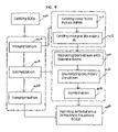
- FIG. 7 is an exemplary flow chart for fingerprint feature extraction for a local region, according to one embodiment of the present invention.
- FIG. 8 is an exemplary diagram for setting partial differential equation, according to one embodiment of the present invention.
- FIG. 9 is an exemplary diagram for getting simultaneous difference equations, according to one embodiment of the present invention.
- FIG. 10A is an exemplary drawing of two adjacent discrete points for discretization of first derivatives along with X-direction, according to one embodiment of the present invention.
- FIG. 10B is an exemplary drawing of two adjacent discrete points for discretization of first derivatives along with Y-direction, according to one embodiment of the present invention.
- FIG. 10C is an exemplary drawing of three adjacent discrete points for discretization of second derivatives along with X-direction, according to one embodiment of the present invention.
- FIG. 10D is an exemplary drawing of three adjacent discrete points for discretization of second derivatives along with Y-direction, according to one embodiment of the present invention.
- FIG. 10E is an exemplary drawing of four adjacent discrete points for discretization of mixed derivatives, according to one embodiment of the present invention.
- FIG. 11A is an exemplary drawing for performing first and second derivatives discrete by selecting referent points as adjacent points near a boundary line, according to one embodiment of the present invention
- FIG. 11B is an exemplary drawing for mixing derivatives discrete by selecting referent points as adjacent points near a boundary line, according to one embodiment of the present invention.
- FIG. 12A illustrates the relationship between a continuous boundary and a discrete boundary
- FIG. 12B illustrates the discretization of the continuous and differentiable function on a numerical boundary
- FIG. 13 is an exemplary flow chart showing the steps performed for solving a SDE, according to one embodiment of the present invention.
- FIG. 14 shows an interpolated point and its 3*3 neighboring mesh points
- FIG. 15 illustrates the operation of mapping an SDE solution back into an image, according to one embodiment of the present invention
- FIG. 16 shows an exemplary result of local solution mapping
- FIG. 17 shows an exemplary enhanced image obtained by mapping a solution to the entire area of an original fingerprint image.
- the present invention establishes numerical relationship between visual appearance of a biometric image and approximate solution of a partial differential equation with a boundary condition. This new approach differs from current methods for the fingerprint image processing. Conventional approaches employ image processing techniques for enhancement and feature extraction. In contrast, the present invention builds and utilizes a mathematical model of a local shape of the biometric image, establishes the relationship between local region status and partial differential equation, and then determines the features of the local shape by solving the numerical equations.
- a fingerprint identification system includes various processing stages as shown in FIG. 1 .
- Feature extraction can be divided into two main operations: (a) image enhancement and (b) feature selection, as shown in FIG. 2 .
- the critical operation in feature extraction is the image enhancement due to the presence of noise in the fingerprint image.
- a fingerprint is used as an example for simplicity purposes, the techniques of the present invention can be used for other biometric images, such as palm images, facial images, eyes iris images, or any other flow-like images such as texture images and the like.
- FIG. 3 shows an example of good quality fingerprint image.
- the set of fingerprint features is restricted to two types of minutiae: bifurcations and ridge endings.
- bifurcations and ridge endings Some examples of bifurcations and ridge endings are shown in FIGS. 4(A) and 4(B) , respectively. More complex fingerprint features can be expressed as a combination of these two basic features.
- FIG. 5(A) gives an example of a short ridge that can be considered as a pair of ridge endings
- FIG. 5(B) shows an enclosure that can be considered as a collection of two bifurcations.
- the fingerprint image may be segmented into local regions.
- the size of each local region is selected to allow for at least two ridges in the region.
- the method of the present invention is independent of the position of the local region. That is, the same steps can be performed on each local region of the fingerprint image for processing the entire fingerprint image. However, for simplicity reasons, the following description is related to one (local) region of the fingerprint image.
- FIG. 7 illustrates an exemplary flow chart for enhancing and extracting features from each local region.
- some intrinsic properties of the fingerprint image are calculated according to the local ridge pattern.
- a partial differential equation is established by mapping the intrinsic properties into the coefficients of the equation and a boundary condition is determined.
- integralization, discretization and transformation steps are performed on the image.
- Each derivative and variable items of the partial differential equation with respect to each mesh points in local region of the fingerprint is replaced so as to obtain corresponding simultaneous difference equations, as shown in block 704 .
- a numerical method is then employed to solve the corresponding simultaneous difference equations in block 706 .
- the solution is mapped back into the local region of the fingerprint image.
- the fingerprint shape and feature are determined by using normalization and interpolation processes, as depicted in block 709 .
- a 1 , A 2 , A 3 , A 4 , A 5 and A 6 are weight coefficients of the partial differential equation.
- FIG. 8 is an exemplary flow chart showing steps of setting initial condition and boundary condition. Five values related to intrinsic properties of the local region are calculated to initialize the PDE (block 804 ). Then, the weight coefficients of the partial differential equation are determined by the intrinsic property values.
- the local region should be normalized (block 808 ) so that correct mean and variance of local region can be obtained.
- the steps involved in normalizing algorithm are as follows:
- N is total number pixels in region R; F(I,J) is gray value of the fingerprint image at point (I,J).
- normalization is a pixel-wise operation.
- the purpose of normalization is to reduce the variations in gray-level values along ridges and valleys, which facilitates the subsequent processing. Due to the presence of noise, smudges, and breaks in ridges in the input fingerprint image, the estimated local property values, P, Q, and V, may not be accurate or stable.
- Typical fingerprint smooth operator such as histogram modeling described in Anil K. Jain, Fundamentals of Digital image processing, Prentice Hall, Englewood Cliffs, N.J., 1989; and median filter described in Jae S. Lim, Two-dimensional Signal and Image Processing, Prentice Hall, Englewood Cliffs, N.J., 1990, the entire contents of which are hereby incorporated by reference, can be used to modify the local region.
- ⁇ y (I,J) and ⁇ y (I,J) be the gradient magnitude in x and y directions, respectively, at pixel (I,J) of the image.
- p 1 , p 2 are positive numbers and p 2 is negative number
- ⁇ (I,J) is an estimate of the local ridge orientation at the block centered at pixel (I,J).
- the gradient operator may vary from the simple Sobel operator described in Sanjit K. Mitra and James F. Kaiser “Handbook for Digital Signal Processing”, A Wiley-Interscience Publication. John Wiley & Sons, 1993 to a more complex Marr-Hildreth operator described in D. Marr, Vision: A Computational Investigation into the Human Representation and Processing of Visual Information. W.H. Freeman and Company. New York, 1982, the contents of which are hereby incorporated by reference.
- Local ridge frequency is defined as frequency of ridge and valley structures in a local neighborhood along the direction normal to the local ridge orientation. Local ridge frequency is another intrinsic property of a fingerprint image.
- the steps involved in local ridge frequency estimation W are as follows:
- Frequency estimation is a window-wise operation. As described above, local ridge frequency W is obtained as the average frequency of the sequence frequency in a window. When the window to be processed contains corrupted ridges and valleys, the sequence of pixels that appear maximal or minimal value need to be well selected. In some cases, interpolations need to be performed on pixel sequence obtained in that window.
- a 1 P*P *( P*P+Q*Q )* W*W
- a 2 2*(sqrt( u*u ⁇ P*P*W*W )*sqrt( v ⁇ Q*Q*W*W ))/ W
- a 3 Q*Q ( P*P+Q*Q )* W*W
- a 4 u*q+v
- a 5 ⁇ v*p ⁇ u
- 6 a *( P*P+Q*Q )+ b (6f)
- a simulation of the partial differential equation for setting optimal initial parameters for system and evaluation of results shows that the selection of constants involves a trade-off between complexity and accuracy. That is, the more optimal the parameters, the more sophisticated ridge information may be created but, the partial differential equation would be more prone to noise. On the other hand, the less optimal the parameters, the less noise prone the system is and less computation time is required. However in this case, detailed ridge shape loss increases.
- the PDE is completely determined by intrinsic properties of the local region as its boundary conditions.
- a close boundary is drawn out manually, or by a computer routine within the respective local region, as shown in block 814 .
- the boundary conditions are then set in block 816 .
- B is denoted as a boundary in local region R.
- the partial differential equation (1) including the following boundary condition expresses a solvable mathematical problem.
- B 1 (x, y) and B 2 (x, y) are the continuous function and differentiable function defined on the boundary S, respectively.
- the enhancement of local ridge shape of fingerprint is considered as the solution of the corresponding PDE under boundary condition. So far, the relationship between a special partial differential equation which governs a fluid flow phenomenon and local intrinsic properties of a fingerprint image is established and the boundary condition related to the gray-level variations of local region in the fingerprint is determined. Next, the partial differential equation needs to be solved with the given boundary condition and the solution to be applied to the local regions of the fingerprint.
- FIG. 9 is an exemplary block diagram showing overall procedures involved in solving the PDE (block 706 of FIG. 7 ).
- Integralization step of block 904 produces a group of integral points within the local region R and an integral boundary IB (block 912 ):
- (X 0 , Y 0 ) is top left point of the image
- W(F) is the width of the image
- H(F) is the height of the image.
- each derivative included in the original partial differential equation (1) is converted into a discretized equation.
- the numerical equation is the result of discretization based upon the integration of inner points within the boundary B.
- the first derivative of the partial differential equation is expressed as a difference of two adjacent discrete points, as shown in FIGS. 10( a ) and 10 ( b ).
- the second derivative of the equation includes three adjacent discrete points, as shown in FIGS. 10( c ), and 10 ( d ).
- the mix derivative (9e) depends on four discrete points, as shown in FIG. 10( e ).
- an inner mesh point may not have enough adjacent points to support derivatives replacement.
- neighboring points outside of local region should be selected as adjacent points.
- FIG. 11( a ) gives an example of first and second derivatives select neighboring points as adjacent points.
- FIG. 11( b ) shows a mix derivatives replacement supporting by three neighboring points.
- f 1 and f 2 are constants that are predetermined according to the brightness and contrast of the image and F(X, Y) is the gray value at point (X, Y) on the integral boundary IB.
- the differentiable function B 2 (x, y) defined on the continuous boundary S is replaced with a numerical function D 1 (X,Y) defined on a numerical boundary IB.
- FIG. 12( b ) is an exemplary diagram for explaining the discretization of the continuous and differentiable function on a numerical boundary IB.
- (I,J) is a inner mesh point of the local region of the fingerprint image
- (I 0 , J 0 ) and (I 1 , J 1 ) are adjacent points along the numerical boundary line
- H is a predetermined step length
- h is the distance between two points (I 0 , J 0 ) and (I 1 , J 1 ).
- C 1 A 2/( H*H );
- C 2 [ A 1/ H*H ) ⁇ A 2/( H*H )+ A 4/ H];
- C 3 [ A 3/( H*H ) ⁇ A 2/( H*H )+ A 5/ H];
- C 4 A 2/( H*H );
- C 5 A 3/( H*H );
- C 6 [ A 2/( H*H ) ⁇ 2* A 1/( H*H ) ⁇ 2* A 3/( H*H ) ⁇ A 4/ H ⁇ A 5 /H+A 6].
- simultaneous difference equations (SDE)
- SDE simultaneous difference equations
- the simultaneous difference equations to be handled are limited to the orthogonal mesh points which spread over a given region, and the numerical operations (referred to as integralization, discretization and transformation) are calculated only for the mesh points. That is, the simultaneous difference equations can be modified only in the position where the image points are selected as inner mesh points. For such reason, preferably an optimal mesh point selection should be done before the numerical operation.
- the step length H is flexible and can be set according to different criteria. For example, longer step length may be chosen at a region where the frequency of the ridge pattern is low, or shorter step length may be chosen at higher ridge frequency region to generate more inner mash point.
- the original partial differential equation (1) with boundary condition (7) is replaced by the simultaneous difference equations (SDE) that includes discrete values. That is, the original equation (1) with (7) is approximated as a group of discrete equations.
- the numerical solution of the SDE may be carried out by a general-purpose computer.
- FIG. 15 depicts an exemplary flow chart of the steps performed for solving the SDE.
- Galerkin's method (described in J. N. Reddy. “An Introduction to the Finite Element Method” McGraw-Hill, Inc., 1993, the contents of which are hereby incorporated by reference) is employed to solve the simultaneous difference equations.
- the detailed description of Galerkin's method is beyond the scope of this invention.
- main steps of Galerkin's method are described as following:
- A is a coefficient item and U is the object item.
- interpolation is used to calculate the value.
- the enhanced value at a position other than a mesh point is interpolated based on the value of the neighboring mesh points.
- neighboring mesh points sequence is quadratically selected and both size m and n are set to 3.
- FIG. 14 shows an interpolated point and its 3*3 neighboring mesh points.
- a solution for each pixel in the image is obtained with different precision.
- the gray level precision of image for computer processing is typically set to 8-bit (namely a byte) in which the minimum gray value is 0 and maximum gray value is 255.
- a normalization process described as follow is then used to map the solution back into the image.
- FIG. 15 illustrates the operation of mapping the SDEs solution back into the image (block 1502 ).
- minimum value and maximum value is calculated in the solution, and the minimum and maximum value denoted as min (R) and max (R), respectively.
- the solution at point (I,J) is denoted as v(I,J)*3.
- the local region R is then enhanced by placing the value W(I,J) at position (I,J).
- the size of local region R in normalization is set in such a manner to cover at two ridges.
- FIG. 16 shows an exemplary result of local solution mapping.
- FIG. 17 shows an exemplary enhanced image that is obtained by mapping the solution to the entire original fingerprint image.
- the present invention may be implemented by a computer software programmed to perform the steps involved.
- a Digital Signal Processor (DSP) chip may be programed to perform the steps of the present invention.
- a special electronic circuit such as an Integrated Chip (IC), maybe designed to carry out the steps of the present invention.
Abstract
Description
-
- M and V denote the estimated mean and variance of the gray-level values in the local region respectively.
- P and Q are the first and second components of the local ridge oriental vector respectively.
- W is the local ridge frequency.
M=(1/N)ΣΣF(I,J) (I,J)∈R (2a)
V=(1/N)ΣΣ(F(I,J)−M(F))*(F(I,J)−M(F)) (I,J)∈R (2b)
R(I,J)=m+sqrt((v*(F(I,J)−M)*(F(I,J)−M))/V, if (I,J)>M;
R(I,J)=m−sqrt((v*(F(I,J)−M)*(F(I,J)−M))/V), otherwise (2c)
where m and v are the desired mean and variance values, respectively.
∂x(I,J)=(p1*F(I−d,J)+p2*F(I,J)+p3*(F(I+d,J))/p,
∂x(I,J)=(p1*F(I,J−d)+p2*F(I,J)+p3*(F(I,J+d))/p (3a)
p=p1+p2+p3;
ξx(I,J)=ΣΣ2*∂x(u,v)*∂y(u,v), (u,v)∈B(k) (3b)
ζy(I,J)=ΣΣ(∂∂x(u,v)*∂∂y(u,v)), (u,v)∈B(k) (3c)
θ(I,J)=(½)a tan{ξx(I,J)/ζ)ζyI,J)} (3d)
P=(1/n)Σ cos(2*θ(I,J)) (I,J)∈R (4a)
Q=(1/n)Σ sin(2*θ(I,J)) (I,J)∈R (4b)
Where n is the total number of pixels calculated at the local region R.
-
- 1. Divide the local region R into small windows of size b*b. Denote the window centered at pixel (I,J) as wnd(I,J).
- 2. For each window centered at pixel (I,J), estimate the main oriental vector (p, q).
- 3. For each window centered at pixel (I,J), compute the minimal value and maximal value within a block of appropriate size, which depend directly on the resolution of the fingerprint image. In practice, as fingerprint images are scanned at resolution of 500 dpi, the size of block can be fixed at 10*10.
- 4. For each window centered at pixel (I,J), get a sequence of pixels that take minimal and maximal value along the direction (a, b). Where (a, b) is orthogonal vector of the main oriental vector (p, q). Denote the sequence of pixel as seq(I,J).
- 5. Calculate the frequency of seq(I,J) at each window centered at pixel (I,J) according to the differential value between connected elements in seq(I,J). Denote the frequency of seq(I,J) as freq(I,J).
- 6. Estimate the local ridge frequency by following equation:
W=(1/K)ΣΣfreq(u,v) (u, v)∈wnd(I,J) (5)
A1=P*P*(P*P+Q*Q)*W*W, (6a)
A2=2*(sqrt(u*u−P*P*W*W)*sqrt(v−Q*Q*W*W))/W, (6b)
A3=Q*Q(P*P+Q*Q)*W*W, (6c)
A4=u*q+v, (6d)
A5=−v*p−u, and (6e)
A6=a*(P*P+Q*Q)+b (6f)
-
- 1. Let=s denote two directions of the coordinate axes of the fingerprint image as X-direction and Y-direction. Along with X-direction and Y-direction, integral points carry out at a desired step length H as follow:
X(I)=X0+I*H, I=0, 1, 2 . . . , W(F); (8a)
Y(J)=Y0+J*H, J=0, 1, 2 . . . , H(F). (8b)
- 1. Let=s denote two directions of the coordinate axes of the fingerprint image as X-direction and Y-direction. Along with X-direction and Y-direction, integral points carry out at a desired step length H as follow:
-
- 2. Map the above integral points into the local region R. Refer to the integral points within region R as inner mesh points of R. Denote the overall inner mesh points of R as IMP(R).
- 3. An integral boundary IB is formed by selecting the nearest inner mesh points of R.
D1(X,Y)=f1*F(X,Y)+f2, (X,Y)∈IB (10)
D2(X,Y)=f1*[F(X1,Y1)−F(X,Y)]/h, (X,Y)∈IB
h=sqrt((X1−X)*(X1−X)+(Y1−Y)*(Y1−Y)); (11)
-
- 1. Each first derivative included in the original partial differential equation (1) is replaced with the discrete form according to the expression (9a) and (9b).
- 2. Each second derivative included in the original partial differential equation (1) is replaced with the discrete form according to the expression (9c) and (9d).
- 3. The mix derivative in the original partial differential equation (1) is replaced with the discrete form according to the expression (9e).
- 4. The continuous function U(X, Y) in the boundary condition (7) is replaced with the discrete function F(I,J) which (I,J) is inner mesh point of local region.
- 5. The continuous function B1(x, y) and the differentiable function B2(x, y) in the boundary condition(7) is replaced with a numerical functions according to the expression (10) and (11), respectively.
- 6. Combing the same items and reducing the void expression, the original PDE (1) with (7) is expressed as a discrete formula:
C1*U(I+H,J+H)+C2*U(I+H,J)+C3*U(I,J+H)+C4*U(I−H,J)+C5*U(I,J−H)+C6*U(I,J)=0; (12)
U(I0,J0)=f1*F(I0,J0)+f2 and U(I1,J1)−U(I0,J0)=(F(I1,J1−F(I0,J0))/h. (13)
C1=A2/(H*H); (14a)
C2=[A1/H*H)−A2/(H*H)+A4/H]; (14b)
C3=[A3/(H*H)−A2/(H*H)+A5/H]; (14c)
C4=A2/(H*H); (14d)
C5=A3/(H*H); (14e)
C6=[A2/(H*H)−2*A1/(H*H)−2*A3/(H*H)−A4/H−A5/H+A6]. (14f)
A{U}=c (15)
-
- 1. Express the simultaneous difference equations in a standard from as
A{U}=f (16)
- 1. Express the simultaneous difference equations in a standard from as
-
- 2. Select a complete element sequence {V(k)} (k=1, 2, 3, YY), and a appropriate number n.
- 3. Take a approximate solution which express as
U(n)=Σa(k)*V(k) (17)
Σa(k)*(A*V(k),V(j))=(f,V(j))(j=1, 2 . . . , n) (18)
-
- 4. Get the solution of a(k) and replace back into the expression (16), the approximate solution U(n) is obtained.
-
- 1. For each point (x, y) which is not selected as a mesh point in the image, get the neighboring mesh points sequence:
P(i,j)=(x(i),y(j)) i=1,2, . . . , m; j=1,2, . . . , n.
- 1. For each point (x, y) which is not selected as a mesh point in the image, get the neighboring mesh points sequence:
{v(i,j)} i=1,2, . . . , m; j=1,2, . . . , n.
-
- 2. Set a Lagrange polynomial with respect to x as:
α(x,i)=ω(x)/((x−x(i))*τ(x(i)) i=1,2 . . . , m (19a)
- 2. Set a Lagrange polynomial with respect to x as:
ω(x)=π(x−x(i)) (19b)
τ(x(i))=(x(i)−x(1))* . . . (x(i)−x(i−1))*(x(i)−x(i=1))* . . . (x(i)−x(n)) (19c)
-
- 3. Set a Lagrange polynomial with respect to y as:
β(y,j)=ω(y)/((y−y(j))*τ(y(j)) j=1,2 . . . , n (19d)
- 3. Set a Lagrange polynomial with respect to y as:
ω(y)=π(y−y(j)) (19e)
and τ(y(j)) is defined as
(y(j))=(y(j)−y(1))* . . . (y(j)−y(j−1))*(y(j)−y(j+1))* . . . (y(j)−(y(n)) (19f)
-
- 4. Calculate the value at point (x, y) as
v(x,y)=ΣΣv(i,j)*α(x,i)*β(y,j) (19g)
- 4. Calculate the value at point (x, y) as
Claims (20)
Priority Applications (1)
| Application Number | Priority Date | Filing Date | Title |
|---|---|---|---|
| US11/336,130 US7194393B2 (en) | 2001-09-05 | 2006-01-19 | Numerical model for image feature extraction |
Applications Claiming Priority (3)
| Application Number | Priority Date | Filing Date | Title |
|---|---|---|---|
| US31721901P | 2001-09-05 | 2001-09-05 | |
| US10/047,535 US7020591B1 (en) | 2001-09-05 | 2002-01-15 | Partial differential equation model for image feature extraction and identification |
| US11/336,130 US7194393B2 (en) | 2001-09-05 | 2006-01-19 | Numerical model for image feature extraction |
Related Parent Applications (1)
| Application Number | Title | Priority Date | Filing Date |
|---|---|---|---|
| US10/047,535 Continuation US7020591B1 (en) | 2001-09-05 | 2002-01-15 | Partial differential equation model for image feature extraction and identification |
Publications (2)
| Publication Number | Publication Date |
|---|---|
| US20060115131A1 US20060115131A1 (en) | 2006-06-01 |
| US7194393B2 true US7194393B2 (en) | 2007-03-20 |
Family
ID=36084746
Family Applications (2)
| Application Number | Title | Priority Date | Filing Date |
|---|---|---|---|
| US10/047,535 Active 2024-06-10 US7020591B1 (en) | 2001-09-05 | 2002-01-15 | Partial differential equation model for image feature extraction and identification |
| US11/336,130 Expired - Lifetime US7194393B2 (en) | 2001-09-05 | 2006-01-19 | Numerical model for image feature extraction |
Family Applications Before (1)
| Application Number | Title | Priority Date | Filing Date |
|---|---|---|---|
| US10/047,535 Active 2024-06-10 US7020591B1 (en) | 2001-09-05 | 2002-01-15 | Partial differential equation model for image feature extraction and identification |
Country Status (1)
| Country | Link |
|---|---|
| US (2) | US7020591B1 (en) |
Cited By (21)
| Publication number | Priority date | Publication date | Assignee | Title |
|---|---|---|---|---|
| US20070112525A1 (en) * | 2005-11-16 | 2007-05-17 | Songtao Li | System and device for image-based biological data quantification |
| US20080273771A1 (en) * | 2007-05-01 | 2008-11-06 | Ming Hsieh | Apparatus for capturing a high quality image of a moist finger |
| US20080304723A1 (en) * | 2007-06-11 | 2008-12-11 | Ming Hsieh | Bio-reader device with ticket identification |
| US20090154779A1 (en) * | 2007-12-14 | 2009-06-18 | Validity Sensors, Inc. | System and method to remove artifacts from fingerprint sensor scans |
| US20090268988A1 (en) * | 2002-02-14 | 2009-10-29 | Cogent Systems, Inc. | Method and apparatus for two dimensional image processing |
| US20100027852A1 (en) * | 2004-11-12 | 2010-02-04 | Ming Hsieh | System and Method for Fast Biometric Pattern Matching |
| US20110175703A1 (en) * | 2010-01-15 | 2011-07-21 | Benkley Iii Fred G | Electronic Imager Using an Impedance Sensor Grid Array Mounted on or about a Switch and Method of Making |
| US20110188709A1 (en) * | 2010-02-01 | 2011-08-04 | Gaurav Gupta | Method and system of accounting for positional variability of biometric features |
| US8041956B1 (en) | 2010-08-16 | 2011-10-18 | Daon Holdings Limited | Method and system for biometric authentication |
| US20120321142A1 (en) * | 2011-06-15 | 2012-12-20 | Honeywell International Inc. | Quality driven image processing for ocular recognition system |
| US8421890B2 (en) | 2010-01-15 | 2013-04-16 | Picofield Technologies, Inc. | Electronic imager using an impedance sensor grid array and method of making |
| US8866347B2 (en) | 2010-01-15 | 2014-10-21 | Idex Asa | Biometric image sensing |
| US20150278574A1 (en) * | 2014-02-12 | 2015-10-01 | Apple Inc. | Processing a Fingerprint for Fingerprint Matching |
| US9576126B2 (en) | 2014-02-13 | 2017-02-21 | Apple Inc. | Updating a template for a biometric recognition device |
| US9665785B2 (en) | 2012-06-29 | 2017-05-30 | Apple Inc. | Enrollment using synthetic fingerprint image and fingerprint sensing systems |
| US9710691B1 (en) * | 2014-01-23 | 2017-07-18 | Diamond Fortress Technologies, Inc. | Touchless fingerprint matching systems and methods |
| US9798917B2 (en) | 2012-04-10 | 2017-10-24 | Idex Asa | Biometric sensing |
| US10039965B1 (en) * | 2017-11-22 | 2018-08-07 | Callaway Golf Company | Iron-type golf club head with damping features |
| US10372962B2 (en) | 2012-06-29 | 2019-08-06 | Apple Inc. | Zero fingerprint enrollment system for an electronic device |
| US11373439B1 (en) | 2013-03-14 | 2022-06-28 | Telos Corporation | Touchless fingerprint matching systems and methods |
| US11521316B1 (en) | 2019-04-03 | 2022-12-06 | Kentucky Imaging Technologies | Automatic extraction of interdental gingiva regions |
Families Citing this family (53)
| Publication number | Priority date | Publication date | Assignee | Title |
|---|---|---|---|---|
| US7020591B1 (en) * | 2001-09-05 | 2006-03-28 | Cogent Systems, Inc | Partial differential equation model for image feature extraction and identification |
| US8447077B2 (en) * | 2006-09-11 | 2013-05-21 | Validity Sensors, Inc. | Method and apparatus for fingerprint motion tracking using an in-line array |
| US8077935B2 (en) | 2004-04-23 | 2011-12-13 | Validity Sensors, Inc. | Methods and apparatus for acquiring a swiped fingerprint image |
| US8131026B2 (en) | 2004-04-16 | 2012-03-06 | Validity Sensors, Inc. | Method and apparatus for fingerprint image reconstruction |
| US8175345B2 (en) | 2004-04-16 | 2012-05-08 | Validity Sensors, Inc. | Unitized ergonomic two-dimensional fingerprint motion tracking device and method |
| US8358815B2 (en) * | 2004-04-16 | 2013-01-22 | Validity Sensors, Inc. | Method and apparatus for two-dimensional finger motion tracking and control |
| US8229184B2 (en) * | 2004-04-16 | 2012-07-24 | Validity Sensors, Inc. | Method and algorithm for accurate finger motion tracking |
| US8165355B2 (en) * | 2006-09-11 | 2012-04-24 | Validity Sensors, Inc. | Method and apparatus for fingerprint motion tracking using an in-line array for use in navigation applications |
| DE602005022900D1 (en) | 2004-10-04 | 2010-09-23 | Validity Sensors Inc | FINGERPRINTER CONSTRUCTIONS WITH ONE SUBSTRATE |
| US7565548B2 (en) * | 2004-11-18 | 2009-07-21 | Biogy, Inc. | Biometric print quality assurance |
| US8385612B2 (en) * | 2005-06-30 | 2013-02-26 | Nec Corporation | Fingerprint image background detection apparatus and detection method |
| US8107212B2 (en) * | 2007-04-30 | 2012-01-31 | Validity Sensors, Inc. | Apparatus and method for protecting fingerprint sensing circuitry from electrostatic discharge |
| US20110002461A1 (en) * | 2007-05-11 | 2011-01-06 | Validity Sensors, Inc. | Method and System for Electronically Securing an Electronic Biometric Device Using Physically Unclonable Functions |
| US8290150B2 (en) * | 2007-05-11 | 2012-10-16 | Validity Sensors, Inc. | Method and system for electronically securing an electronic device using physically unclonable functions |
| US8276816B2 (en) * | 2007-12-14 | 2012-10-02 | Validity Sensors, Inc. | Smart card system with ergonomic fingerprint sensor and method of using |
| US8005276B2 (en) | 2008-04-04 | 2011-08-23 | Validity Sensors, Inc. | Apparatus and method for reducing parasitic capacitive coupling and noise in fingerprint sensing circuits |
| US8116540B2 (en) * | 2008-04-04 | 2012-02-14 | Validity Sensors, Inc. | Apparatus and method for reducing noise in fingerprint sensing circuits |
| GB2474999B (en) * | 2008-07-22 | 2013-02-20 | Validity Sensors Inc | System and method for securing a device component |
| US20100074551A1 (en) * | 2008-09-22 | 2010-03-25 | Microsoft Corporation | Learning-based partial differential equations for computer vision |
| US8391568B2 (en) * | 2008-11-10 | 2013-03-05 | Validity Sensors, Inc. | System and method for improved scanning of fingerprint edges |
| US8600122B2 (en) * | 2009-01-15 | 2013-12-03 | Validity Sensors, Inc. | Apparatus and method for culling substantially redundant data in fingerprint sensing circuits |
| US8278946B2 (en) | 2009-01-15 | 2012-10-02 | Validity Sensors, Inc. | Apparatus and method for detecting finger activity on a fingerprint sensor |
| US20100176892A1 (en) * | 2009-01-15 | 2010-07-15 | Validity Sensors, Inc. | Ultra Low Power Oscillator |
| US20100180136A1 (en) * | 2009-01-15 | 2010-07-15 | Validity Sensors, Inc. | Ultra Low Power Wake-On-Event Mode For Biometric Systems |
| US8374407B2 (en) | 2009-01-28 | 2013-02-12 | Validity Sensors, Inc. | Live finger detection |
| US20100208953A1 (en) * | 2009-02-17 | 2010-08-19 | Validity Sensors, Inc. | Illuminated Fingerprint Sensor and Method |
| US9400911B2 (en) | 2009-10-30 | 2016-07-26 | Synaptics Incorporated | Fingerprint sensor and integratable electronic display |
| US9336428B2 (en) | 2009-10-30 | 2016-05-10 | Synaptics Incorporated | Integrated fingerprint sensor and display |
| US9274553B2 (en) | 2009-10-30 | 2016-03-01 | Synaptics Incorporated | Fingerprint sensor and integratable electronic display |
| WO2011092827A1 (en) * | 2010-01-28 | 2011-08-04 | 富士通株式会社 | Biological-information processing device, biological-information processing method, and biological-information processing program |
| US9666635B2 (en) | 2010-02-19 | 2017-05-30 | Synaptics Incorporated | Fingerprint sensing circuit |
| US8716613B2 (en) * | 2010-03-02 | 2014-05-06 | Synaptics Incoporated | Apparatus and method for electrostatic discharge protection |
| US9001040B2 (en) | 2010-06-02 | 2015-04-07 | Synaptics Incorporated | Integrated fingerprint sensor and navigation device |
| US8331096B2 (en) | 2010-08-20 | 2012-12-11 | Validity Sensors, Inc. | Fingerprint acquisition expansion card apparatus |
| US8594393B2 (en) | 2011-01-26 | 2013-11-26 | Validity Sensors | System for and method of image reconstruction with dual line scanner using line counts |
| US8538097B2 (en) | 2011-01-26 | 2013-09-17 | Validity Sensors, Inc. | User input utilizing dual line scanner apparatus and method |
| GB2489100A (en) | 2011-03-16 | 2012-09-19 | Validity Sensors Inc | Wafer-level packaging for a fingerprint sensor |
| US10043052B2 (en) | 2011-10-27 | 2018-08-07 | Synaptics Incorporated | Electronic device packages and methods |
| US8959082B2 (en) | 2011-10-31 | 2015-02-17 | Elwha Llc | Context-sensitive query enrichment |
| US9195877B2 (en) | 2011-12-23 | 2015-11-24 | Synaptics Incorporated | Methods and devices for capacitive image sensing |
| US9785299B2 (en) | 2012-01-03 | 2017-10-10 | Synaptics Incorporated | Structures and manufacturing methods for glass covered electronic devices |
| US9251329B2 (en) | 2012-03-27 | 2016-02-02 | Synaptics Incorporated | Button depress wakeup and wakeup strategy |
| US9268991B2 (en) | 2012-03-27 | 2016-02-23 | Synaptics Incorporated | Method of and system for enrolling and matching biometric data |
| US9137438B2 (en) | 2012-03-27 | 2015-09-15 | Synaptics Incorporated | Biometric object sensor and method |
| US9600709B2 (en) | 2012-03-28 | 2017-03-21 | Synaptics Incorporated | Methods and systems for enrolling biometric data |
| US9152838B2 (en) | 2012-03-29 | 2015-10-06 | Synaptics Incorporated | Fingerprint sensor packagings and methods |
| CN102799876B (en) * | 2012-08-02 | 2015-03-11 | 北京海鑫科金高科技股份有限公司 | Method for separating superimposed fingerprint images |
| US9665762B2 (en) | 2013-01-11 | 2017-05-30 | Synaptics Incorporated | Tiered wakeup strategy |
| KR101631474B1 (en) * | 2015-01-13 | 2016-06-17 | 동국대학교 산학협력단 | Three dimensional model creating method for digital manufacture |
| CN104732217B (en) * | 2015-03-27 | 2018-04-06 | 电子科技大学 | A kind of adaptive template size Fingerprint diretion computational methods |
| CN106022068B (en) * | 2016-05-30 | 2019-04-05 | Oppo广东移动通信有限公司 | A kind of solution lock control method and terminal device |
| CN106503628A (en) * | 2016-09-30 | 2017-03-15 | 北京小米移动软件有限公司 | method and device for fingerprint matching |
| SE1750159A1 (en) * | 2017-02-17 | 2018-08-18 | Fingerprint Cards Ab | Canceling out impairment data in fingerprint images |
Citations (5)
| Publication number | Priority date | Publication date | Assignee | Title |
|---|---|---|---|---|
| US5517419A (en) | 1993-07-22 | 1996-05-14 | Synectics Corporation | Advanced terrain mapping system |
| US5754697A (en) | 1994-12-02 | 1998-05-19 | Fu; Chi-Yung | Selective document image data compression technique |
| US6618076B1 (en) | 1999-12-23 | 2003-09-09 | Justsystem Corporation | Method and apparatus for calibrating projector-camera system |
| US6697538B1 (en) | 1999-07-30 | 2004-02-24 | Wisconsin Alumni Research Foundation | Apparatus for producing a flattening map of a digitized image for conformally mapping onto a surface and associated method |
| US7020591B1 (en) * | 2001-09-05 | 2006-03-28 | Cogent Systems, Inc | Partial differential equation model for image feature extraction and identification |
-
2002
- 2002-01-15 US US10/047,535 patent/US7020591B1/en active Active
-
2006
- 2006-01-19 US US11/336,130 patent/US7194393B2/en not_active Expired - Lifetime
Patent Citations (5)
| Publication number | Priority date | Publication date | Assignee | Title |
|---|---|---|---|---|
| US5517419A (en) | 1993-07-22 | 1996-05-14 | Synectics Corporation | Advanced terrain mapping system |
| US5754697A (en) | 1994-12-02 | 1998-05-19 | Fu; Chi-Yung | Selective document image data compression technique |
| US6697538B1 (en) | 1999-07-30 | 2004-02-24 | Wisconsin Alumni Research Foundation | Apparatus for producing a flattening map of a digitized image for conformally mapping onto a surface and associated method |
| US6618076B1 (en) | 1999-12-23 | 2003-09-09 | Justsystem Corporation | Method and apparatus for calibrating projector-camera system |
| US7020591B1 (en) * | 2001-09-05 | 2006-03-28 | Cogent Systems, Inc | Partial differential equation model for image feature extraction and identification |
Cited By (45)
| Publication number | Priority date | Publication date | Assignee | Title |
|---|---|---|---|---|
| US20090268988A1 (en) * | 2002-02-14 | 2009-10-29 | Cogent Systems, Inc. | Method and apparatus for two dimensional image processing |
| US8254728B2 (en) | 2002-02-14 | 2012-08-28 | 3M Cogent, Inc. | Method and apparatus for two dimensional image processing |
| US8379982B2 (en) | 2004-11-12 | 2013-02-19 | 3M Cogent, Inc. | System and method for fast biometric pattern matching |
| US20100027852A1 (en) * | 2004-11-12 | 2010-02-04 | Ming Hsieh | System and Method for Fast Biometric Pattern Matching |
| US8131477B2 (en) | 2005-11-16 | 2012-03-06 | 3M Cogent, Inc. | Method and device for image-based biological data quantification |
| US20070112525A1 (en) * | 2005-11-16 | 2007-05-17 | Songtao Li | System and device for image-based biological data quantification |
| US8583379B2 (en) | 2005-11-16 | 2013-11-12 | 3M Innovative Properties Company | Method and device for image-based biological data quantification |
| US8275179B2 (en) | 2007-05-01 | 2012-09-25 | 3M Cogent, Inc. | Apparatus for capturing a high quality image of a moist finger |
| US20080273771A1 (en) * | 2007-05-01 | 2008-11-06 | Ming Hsieh | Apparatus for capturing a high quality image of a moist finger |
| US20080304723A1 (en) * | 2007-06-11 | 2008-12-11 | Ming Hsieh | Bio-reader device with ticket identification |
| US8411916B2 (en) | 2007-06-11 | 2013-04-02 | 3M Cogent, Inc. | Bio-reader device with ticket identification |
| US20090154779A1 (en) * | 2007-12-14 | 2009-06-18 | Validity Sensors, Inc. | System and method to remove artifacts from fingerprint sensor scans |
| US8204281B2 (en) | 2007-12-14 | 2012-06-19 | Validity Sensors, Inc. | System and method to remove artifacts from fingerprint sensor scans |
| US8421890B2 (en) | 2010-01-15 | 2013-04-16 | Picofield Technologies, Inc. | Electronic imager using an impedance sensor grid array and method of making |
| US10592719B2 (en) | 2010-01-15 | 2020-03-17 | Idex Biometrics Asa | Biometric image sensing |
| US9600704B2 (en) | 2010-01-15 | 2017-03-21 | Idex Asa | Electronic imager using an impedance sensor grid array and method of making |
| US11080504B2 (en) | 2010-01-15 | 2021-08-03 | Idex Biometrics Asa | Biometric image sensing |
| US20110175703A1 (en) * | 2010-01-15 | 2011-07-21 | Benkley Iii Fred G | Electronic Imager Using an Impedance Sensor Grid Array Mounted on or about a Switch and Method of Making |
| US8791792B2 (en) | 2010-01-15 | 2014-07-29 | Idex Asa | Electronic imager using an impedance sensor grid array mounted on or about a switch and method of making |
| US8866347B2 (en) | 2010-01-15 | 2014-10-21 | Idex Asa | Biometric image sensing |
| US10115001B2 (en) | 2010-01-15 | 2018-10-30 | Idex Asa | Biometric image sensing |
| US9659208B2 (en) | 2010-01-15 | 2017-05-23 | Idex Asa | Biometric image sensing |
| US9268988B2 (en) | 2010-01-15 | 2016-02-23 | Idex Asa | Biometric image sensing |
| US8520903B2 (en) | 2010-02-01 | 2013-08-27 | Daon Holdings Limited | Method and system of accounting for positional variability of biometric features |
| US20110188709A1 (en) * | 2010-02-01 | 2011-08-04 | Gaurav Gupta | Method and system of accounting for positional variability of biometric features |
| US8977861B2 (en) | 2010-08-16 | 2015-03-10 | Daon Holdings Limited | Method and system for biometric authentication |
| US8041956B1 (en) | 2010-08-16 | 2011-10-18 | Daon Holdings Limited | Method and system for biometric authentication |
| US20120321142A1 (en) * | 2011-06-15 | 2012-12-20 | Honeywell International Inc. | Quality driven image processing for ocular recognition system |
| US8879800B2 (en) * | 2011-06-15 | 2014-11-04 | Honeywell International Inc. | Quality driven image processing for ocular recognition system |
| US10088939B2 (en) | 2012-04-10 | 2018-10-02 | Idex Asa | Biometric sensing |
| US10114497B2 (en) | 2012-04-10 | 2018-10-30 | Idex Asa | Biometric sensing |
| US9798917B2 (en) | 2012-04-10 | 2017-10-24 | Idex Asa | Biometric sensing |
| US10101851B2 (en) | 2012-04-10 | 2018-10-16 | Idex Asa | Display with integrated touch screen and fingerprint sensor |
| US10372962B2 (en) | 2012-06-29 | 2019-08-06 | Apple Inc. | Zero fingerprint enrollment system for an electronic device |
| US9665785B2 (en) | 2012-06-29 | 2017-05-30 | Apple Inc. | Enrollment using synthetic fingerprint image and fingerprint sensing systems |
| US10255474B2 (en) | 2012-06-29 | 2019-04-09 | Apple Inc. | Enrollment using synthetic fingerprint image and fingerprint sensing systems |
| US10885293B2 (en) | 2012-06-29 | 2021-01-05 | Apple Inc. | Enrollment using synthetic fingerprint image and fingerprint sensing systems |
| US11475691B2 (en) | 2012-06-29 | 2022-10-18 | Apple Inc. | Enrollment using synthetic fingerprint image and fingerprint sensing systems |
| US11373439B1 (en) | 2013-03-14 | 2022-06-28 | Telos Corporation | Touchless fingerprint matching systems and methods |
| US9710691B1 (en) * | 2014-01-23 | 2017-07-18 | Diamond Fortress Technologies, Inc. | Touchless fingerprint matching systems and methods |
| US20150278574A1 (en) * | 2014-02-12 | 2015-10-01 | Apple Inc. | Processing a Fingerprint for Fingerprint Matching |
| US9514351B2 (en) * | 2014-02-12 | 2016-12-06 | Apple Inc. | Processing a fingerprint for fingerprint matching |
| US9576126B2 (en) | 2014-02-13 | 2017-02-21 | Apple Inc. | Updating a template for a biometric recognition device |
| US10039965B1 (en) * | 2017-11-22 | 2018-08-07 | Callaway Golf Company | Iron-type golf club head with damping features |
| US11521316B1 (en) | 2019-04-03 | 2022-12-06 | Kentucky Imaging Technologies | Automatic extraction of interdental gingiva regions |
Also Published As
| Publication number | Publication date |
|---|---|
| US7020591B1 (en) | 2006-03-28 |
| US20060115131A1 (en) | 2006-06-01 |
Similar Documents
| Publication | Publication Date | Title |
|---|---|---|
| US7194393B2 (en) | Numerical model for image feature extraction | |
| US7072523B2 (en) | System and method for fingerprint image enhancement using partitioned least-squared filters | |
| Hong et al. | Fingerprint image enhancement: algorithm and performance evaluation | |
| Han et al. | Palm vein recognition using adaptive Gabor filter | |
| US7027622B2 (en) | Method for locating face landmarks in an image | |
| US7587083B2 (en) | Image processing device | |
| US7496214B2 (en) | Method of palm print identification | |
| KR101390756B1 (en) | Facial feature detection method and device | |
| US6263091B1 (en) | System and method for identifying foreground and background portions of digitized images | |
| JP2776294B2 (en) | Image feature extraction device and image processing device for skin pattern image | |
| Bellon et al. | New improvements to range image segmentation by edge detection | |
| US7035461B2 (en) | Method for detecting objects in digital images | |
| US6289112B1 (en) | System and method for determining block direction in fingerprint images | |
| US7142699B2 (en) | Fingerprint matching using ridge feature maps | |
| US7970185B2 (en) | Apparatus and methods for capturing a fingerprint | |
| US20040062423A1 (en) | Personal authentication apparatus and personal authentication method | |
| US20150261992A1 (en) | Hand-based biometric analysis | |
| WO1994023390A1 (en) | Apparatus for identifying person | |
| KR20050022306A (en) | Method and Apparatus for image-based photorealistic 3D face modeling | |
| JP2004206656A (en) | Detection device and detection method | |
| KR20010080219A (en) | Image processing apparatus, image processing method, and recording medium | |
| CN107506754A (en) | Iris identification method, device and terminal device | |
| CN112883824A (en) | Finger vein feature recognition device for intelligent blood sampling and recognition method thereof | |
| KR19990074775A (en) | Fingerprint Feature Extraction Method | |
| Kwon et al. | Rolled fingerprint construction using MRF-based nonrigid image registration |
Legal Events
| Date | Code | Title | Description |
|---|---|---|---|
| STCF | Information on status: patent grant |
Free format text: PATENTED CASE |
|
| FPAY | Fee payment |
Year of fee payment: 4 |
|
| AS | Assignment |
Owner name: COGENT, INC., CALIFORNIA Free format text: MERGER;ASSIGNOR:COGENT SYSTEMS, INC.;REEL/FRAME:026376/0381 Effective date: 20040503 Owner name: 3M COGENT, INC., CALIFORNIA Free format text: MERGER AND NAME CHANGE;ASSIGNOR:COGENT, INC.;REEL/FRAME:026376/0673 Effective date: 20101201 |
|
| FEPP | Fee payment procedure |
Free format text: PAT HOLDER NO LONGER CLAIMS SMALL ENTITY STATUS, ENTITY STATUS SET TO UNDISCOUNTED (ORIGINAL EVENT CODE: STOL); ENTITY STATUS OF PATENT OWNER: LARGE ENTITY |
|
| FPAY | Fee payment |
Year of fee payment: 8 |
|
| AS | Assignment |
Owner name: GEMALTO SA, FRANCE Free format text: ASSIGNMENT OF ASSIGNORS INTEREST;ASSIGNOR:3M COGENT, INC.;REEL/FRAME:042962/0397 Effective date: 20170501 |
|
| MAFP | Maintenance fee payment |
Free format text: PAYMENT OF MAINTENANCE FEE, 12TH YEAR, LARGE ENTITY (ORIGINAL EVENT CODE: M1553); ENTITY STATUS OF PATENT OWNER: LARGE ENTITY Year of fee payment: 12 |