US6933886B1 - Signal acquisition using data bit information - Google Patents
Signal acquisition using data bit information Download PDFInfo
- Publication number
- US6933886B1 US6933886B1 US10/316,992 US31699202A US6933886B1 US 6933886 B1 US6933886 B1 US 6933886B1 US 31699202 A US31699202 A US 31699202A US 6933886 B1 US6933886 B1 US 6933886B1
- Authority
- US
- United States
- Prior art keywords
- data
- received signal
- sampled data
- signal
- correlation
- Prior art date
- Legal status (The legal status is an assumption and is not a legal conclusion. Google has not performed a legal analysis and makes no representation as to the accuracy of the status listed.)
- Expired - Lifetime
Links
Images


Classifications
-
- G—PHYSICS
- G01—MEASURING; TESTING
- G01S—RADIO DIRECTION-FINDING; RADIO NAVIGATION; DETERMINING DISTANCE OR VELOCITY BY USE OF RADIO WAVES; LOCATING OR PRESENCE-DETECTING BY USE OF THE REFLECTION OR RERADIATION OF RADIO WAVES; ANALOGOUS ARRANGEMENTS USING OTHER WAVES
- G01S19/00—Satellite radio beacon positioning systems; Determining position, velocity or attitude using signals transmitted by such systems
- G01S19/01—Satellite radio beacon positioning systems transmitting time-stamped messages, e.g. GPS [Global Positioning System], GLONASS [Global Orbiting Navigation Satellite System] or GALILEO
- G01S19/13—Receivers
- G01S19/24—Acquisition or tracking or demodulation of signals transmitted by the system
- G01S19/30—Acquisition or tracking or demodulation of signals transmitted by the system code related
-
- G—PHYSICS
- G01—MEASURING; TESTING
- G01S—RADIO DIRECTION-FINDING; RADIO NAVIGATION; DETERMINING DISTANCE OR VELOCITY BY USE OF RADIO WAVES; LOCATING OR PRESENCE-DETECTING BY USE OF THE REFLECTION OR RERADIATION OF RADIO WAVES; ANALOGOUS ARRANGEMENTS USING OTHER WAVES
- G01S19/00—Satellite radio beacon positioning systems; Determining position, velocity or attitude using signals transmitted by such systems
- G01S19/01—Satellite radio beacon positioning systems transmitting time-stamped messages, e.g. GPS [Global Positioning System], GLONASS [Global Orbiting Navigation Satellite System] or GALILEO
- G01S19/03—Cooperating elements; Interaction or communication between different cooperating elements or between cooperating elements and receivers
- G01S19/05—Cooperating elements; Interaction or communication between different cooperating elements or between cooperating elements and receivers providing aiding data
- G01S19/06—Cooperating elements; Interaction or communication between different cooperating elements or between cooperating elements and receivers providing aiding data employing an initial estimate of the location of the receiver as aiding data or in generating aiding data
-
- G—PHYSICS
- G01—MEASURING; TESTING
- G01S—RADIO DIRECTION-FINDING; RADIO NAVIGATION; DETERMINING DISTANCE OR VELOCITY BY USE OF RADIO WAVES; LOCATING OR PRESENCE-DETECTING BY USE OF THE REFLECTION OR RERADIATION OF RADIO WAVES; ANALOGOUS ARRANGEMENTS USING OTHER WAVES
- G01S19/00—Satellite radio beacon positioning systems; Determining position, velocity or attitude using signals transmitted by such systems
- G01S19/01—Satellite radio beacon positioning systems transmitting time-stamped messages, e.g. GPS [Global Positioning System], GLONASS [Global Orbiting Navigation Satellite System] or GALILEO
- G01S19/03—Cooperating elements; Interaction or communication between different cooperating elements or between cooperating elements and receivers
- G01S19/09—Cooperating elements; Interaction or communication between different cooperating elements or between cooperating elements and receivers providing processing capability normally carried out by the receiver
-
- G—PHYSICS
- G01—MEASURING; TESTING
- G01S—RADIO DIRECTION-FINDING; RADIO NAVIGATION; DETERMINING DISTANCE OR VELOCITY BY USE OF RADIO WAVES; LOCATING OR PRESENCE-DETECTING BY USE OF THE REFLECTION OR RERADIATION OF RADIO WAVES; ANALOGOUS ARRANGEMENTS USING OTHER WAVES
- G01S19/00—Satellite radio beacon positioning systems; Determining position, velocity or attitude using signals transmitted by such systems
- G01S19/01—Satellite radio beacon positioning systems transmitting time-stamped messages, e.g. GPS [Global Positioning System], GLONASS [Global Orbiting Navigation Satellite System] or GALILEO
- G01S19/13—Receivers
- G01S19/24—Acquisition or tracking or demodulation of signals transmitted by the system
Definitions
- the present invention relates to signal processing and, more particularly, to techniques for aiding in the acquisition of a signal using data bit information that is associated with the signal.
- the location of a device may be determined using a global positioning system (“GPS”).
- GPS global positioning system
- a receiver acquires signals from four or more satellite vehicles to obtain a three dimensional location and the current time stamp.
- a receiver may employ multiple channels and the received signal may be processed in each channel to acquire a signal from a single signal source. After acquisition, a delay-locked loop is traditionally used to track the signal source.
- GPS satellite vehicles emit two microwave carrier signals of L1 and L2 frequency.
- the two microwave carrier signals are modulated by: 1) a C/A code (Coarse Acquisition), 2) a P-Code (Precise), and 3) a data message.
- the C/A code is a repeating 1 MHz Pseudo Random Noise (PRN) code that modulates the L1 carrier phase.
- the C/A PRN code comprises 1023 bits in order that are repeated every millisecond.
- the P-Code modulates both the L1 and L2 carrier phases.
- the P-Code is a 10 MHz PRN code.
- the data message modulates the L1-C/A code signal.
- the data message is 50 Hz signal consisting of data bits that encode a time stamp, the GPS satellite vehicle orbit parameters, clock corrections, and other parameters. All of this data is useful for the receiver to know in order to calculate and update its position.
- a receiver may attempt to acquire a signal by: 1) generating a replica PRN code emitted by a satellite vehicle that is potentially visible overhead the receiver, and 2) determining a correlation between the received signal and the suitably modulated replica code.
- the correlation between the received signal and the replica code is performed by calculating both the In Phase (“I”) and Quadrature (“Q”) correlation integrals.
- I In Phase
- Q Quadrature
- One issue that arises is that the signal from the satellite is also modulated by data bits using phase modulation. These data bits are unknown at a standard standalone receiver and as a result, the I and Q correlation integrals can not reliably be extended coherently beyond the length of one data bit.
- One existing approach around this problem is to combine the I and Q correlation integrals non-coherently between data bits. This also helps by mitigating the impact of uncertainty in the carrier modulation frequency.
- One salient disadvantage to the non-coherent approach is that in instances when the received signal is highly degraded (for example, the receiver that is receiving the received signal is inside a building), then the duration of received signal that needs to be processed to compensate for the level of degradation is roughly proportional to the level of degradation raised to the power of two. To illustrate, suppose the received signal is degraded by an additional factor of 100, then the duration of data needed to compensate for the level of degradation is increased proportional to 100 2 if non-coherent processing is done.
- One aspect of the invention is to use the data bit information that is associated with each signal source when calculating the In Phase and Quadrature correlation integrals by using the sampled data associated with the received signal.
- coherent correlation may be performed by breaking the signal into blocks and performing calculations on a block-by-block basis.
- Coherent correlation is the calculation of In Phase and Quadrature correlation integrals for sampled data that is associated with the received signal.
- FIG. 1 is a block diagram that illustrates a system overview of acquiring a signal
- FIG. 2 A and FIG. 2B are block diagrams that illustrate techniques that aid in the acquisition of a signal from one satellite;
- FIG. 3 is a flowchart that illustrates the basic approach for calculating I and Q according to certain embodiments
- FIG. 4 is a flowchart that illustrates the classification of blocks of data according to hypothesized delay values
- FIG. 5 is a flowchart that illustrates the process for handling segments with no data bit change
- FIG. 6 is a flowchart that illustrates the process for handling segments with a data bit change for all shift values
- FIG. 7 is a flowchart that illustrates the process for handling segments with data bit change for some shift values
- FIG. 8 is a flowchart that illustrates a method of increasing computational savings when dealing with a range of ⁇ i values
- FIG. 9 is a block diagram that illustrates the basic approach of summing the (y l , z l ) blocks before the FFT of block 514 of FIG. 5 ;
- FIG. 10 is a block diagram illustrating a computer system on which embodiments of the invention may be implemented.
- FIG. 1 is a block diagram that illustrates a system overview of acquiring a signal.
- Acquisition system 100 comprises a source S of signal emission, a receiver H, a base station B and a server D.
- a source S of signal emission e.g., a source S of signal emission
- a receiver H e.g., a receiver S of signal emission
- a base station B e.g., a base station B
- server D e.g., a server
- the server may be co-located with the base station.
- Examples of sources of signal emission are satellites, terrestrial signal beacons, airborne transmitters, mobile stations, and any other radio or ultrasound transmitter.
- Examples of receivers are Global Positioning System receivers, cell phones with embedded signal receivers, Personal Digital Assistants (PDAs) with embedded signal receivers, personal computers equipped with software radios, and vehicles with signal reception capabilities.
- PDAs Personal Digital Assistants
- Source S may be one of the Global Positioning System (GPS) satellite vehicles that is overhead the location of receiver H.
- GPS Global Positioning System
- a receiver needs to acquire signals from four or more satellite vehicles to obtain a three dimensional location.
- H receives a signal herein referred to as a “received signal”.
- a signal herein referred to as a “received signal”.
- H upon receiving the received signal, H converts the continuous wave form of the received signal into discrete values.
- One method of converting the continuous wave form of the received signal into discrete values is by digitizing the received signal.
- the digitized received signal is herein referred to as “sampled data”.
- H transmits the sampled data to base station B.
- H also transmits to the base station the approximate time that H received the received signal.
- Base station B in turn transmits the sampled data and approximate time to server D.
- Server D processes the sampled data to acquire a signal.
- the signal that is acquired is herein referred to as an “acquired signal”.
- signal acquisition involves correlating the sampled data with a modulated and delayed C/A PRN code that matches the C/A PRN code of the particular GPS satellite vehicle whose emissions might be detectable in the sampled data. If the sampled data does not correlate sufficiently with the correct C/A PRN code, then no signal is acquired.
- Signal acquisition involves the calculation of the In Phase and Quadrature correlation integrals (I and Q correlation integrals) associated with the sampled data.
- the I and Q correlation integrals are evaluated for a plurality of different hypothesized time shifts and Doppler shifts in the modulation.
- a Doppler shift in the modulation is necessary to deal with the effects of sampling clock-rate inaccuracies (referred to as “clock drift”) and the net movement between the receiver and the signal source.
- the delay which is the time it takes an emitted signal to travel from the GPS satellite vehicle to reach the receiver, may be calculated using the parameters of the acquired signal. Such a delay is herein referred to as a “delay value”.
- the delay value corresponding to each of several acquired signals may then be used to calculate the location of the receiver in a given coordinate system. For example, the calculation of the location of the receiver may be performed in an earth-fixed coordinate system.
- FIG. 2 A and FIG. 2B are block diagrams that illustrate techniques that aid in the acquisition of a signal from one satellite.
- the sampled data that is received from receiver H is processed at server D.
- the clock drift of receiver H is determined.
- the clock drift of a receiver is herein referred to as “receiver-doppler information”.
- Various techniques may be used to determine the receiver-doppler information of a receiver. One such technique is described in U.S. patent application Ser. No.
- the set of satellite vehicles that is potentially overhead the receiver H is determined.
- the set of satellite vehicles that is potentially overhead is determined from: 1) the approximate time that the receiver 11 received the received signal, 2) the approximate position of the receiver H in an earth-fixed coordinate system, and 3) the orbital data of the satellite vehicles.
- the approximate position of the receiver H in an earth-fixed coordinate system may be determined by the proximity of the receiver H to a particular base station.
- the proximity of the receiver H to a particular base station may be determined by identifying the base station to which the receiver H transmitted the sampled data and the approximate time for the sampled data to reach the base station from the receiver H.
- it may come from another method of determining location and time.
- the precise orbital data of the entire GPS constellation may be obtained from a Master Control facility such as the one at Schriever United States Air Force Base in Colorado. Alternatively, it may be read from the data messages of the satellites.
- the identification of the set of satellite vehicles that are potentially overhead the receiver H is described further in patent application Ser. No. 09/782,648, filed on Feb. 12, 2001, entitled “Location-Determination Method and Apparatus”, by inventors Benjamin Van Roy, John Tsitsiklis and Andrew Chou.
- a range of hypothesized delay values is determined by estimating the range of the possible delay in time based on the approximate time when the receiver H received the received signal and the approximate position of receiver H in an earth-fixed coordinate system, combined with some knowledge of the uncertainty in those values.
- the determination of a range of hypothesized delay values is described in further detail in patent application Ser. No. 09/888,229, filed on the same day herewith, entitled “Determining the Spatio-Temporal and Kinematic Parameters of a Signal Receiver and Its Clock by Information Fusion”, by inventors Anant Sahai, Andrew Chou, Wallace Mann and Stefano Casadei.
- a signal source is selected for consideration.
- the true modulation frequency of the selected satellite vehicle and the data bit information of the selected satellite vehicle are determined.
- the true modulation frequency of a satellite vehicle incorporates the “satellite-doppler information” and relative receiver motion grouped together as f i , as well as the effect of the receivers sampling rate error f 0 .
- the data bit information refers to the data message being transmitted by the signal source at that time.
- the data bit information indicates when the C/A otherwise repeating PRN codes changes sign or “flips” during signal emission. Such data bit information may be obtained from a reference receiver that gets a separate measurement of this signal source's signal, or be calculated on the basis of prediction based on historical and known values.
- the sampled data is mixed to a new frequency using the receiver-doppler information and the satellite-doppler information to produce complex valued re-mixed sampled data.
- the remixed sampled data is divided into small blocks of data. In certain embodiments, the block size of each of the small blocks of data corresponds to 1 millisecond of the re-mixed sampled data.
- control passes to block 250 of FIG. 2 B.
- the correlation integrals are calculated for each small block of data.
- the C/A PRN code repeats every 1 millisecond and may flip only every 20 milliseconds. However, the time may be known only approximately and hence the blocks may not be able to be classified with certainty as to which one corresponds to which position within the 20 millisecond time span before potential flips. Thus, for those blocks of data for which a flip may occur, the I and Q correlation integrals are calculated both with and without a change in sign.
- the I and Q correlation integrals are calculated both with and without a change in sign.
- the I and Q correlation integrals may be calculated by using a variety of techniques.
- the I and Q correlation integrals may be calculated by performing a numerical integration of the I and Q correlation integrals or by using a frequency domain technique such as a Fast Fourier Transform (“FFT”).
- FFT Fast Fourier Transform
- the calculated I correlation integral is summed over the blocks of data.
- the summation takes into account the sign change due to any flips.
- the calculated Q correlation integral is summed over the blocks of data.
- the summation takes into account the sign change due to any flips.
- ⁇ and ⁇ overscore (Q) ⁇ represents the summation of the I and Q correlation integrals respectively
- the magnitude of ( ⁇ , ⁇ overscore (Q) ⁇ ) is calculated to produce a set of magnitude values that correspond to the range of hypothesized delay values.
- the magnitude values are plotted against the range of hypothesized delay values to form a graph, and it is determined whether a major peak may be identified from the graph. In certain embodiments of the invention, a major peak is identified by examining the values of the highest peak. If the height of the peak exceeds a pre-selected threshold value, then the highest peak is the major peak and the operation stops as is indicated by block 260 . Otherwise, at step 262 , control is returned to block 208 of FIG. 2 A.
- the signals from at least 4 satellite vehicles are acquired in order to solve for the location and time of the receiver H. If there are fewer than 4 degrees of freedom, then fewer satellites may be needed. Additional acquisitions are also helpful in reducing error.
- the technique as described with reference to FIG. 2 A and FIG. 2B may be used to acquire signals from each of the 4 or more satellite vehicles.
- the sampled signal is denoted by x k where k ranges from 1 to K and x k represents the k-th sample from the received signal.
- the inter-sample duration of time is denoted by ⁇ .
- the pre-sampling signal processing has shifted the signal to an intermediate frequency f IF from an original carrier frequency of f c .
- (f IF +f 0 +f t ) represents the modulation frequency at which it is desired to calculate the correlations
- ⁇ t represents the unmodulated signal with which it is desired to correlate the data
- ⁇ t represents the hypothesized shift of the ⁇ t signal.
- ⁇ t is herein also referred to as the hypothesized delay value.
- the ⁇ t signal itself consists of a lowpass filtering (by an operator G) of a repeating binary PRN code (represented by ⁇ t (t) taking values in ⁇ +1, ⁇ 1 ⁇ ) slowly modulated by a binary sequence of data bits (represented by a signal v i (t) also taking values in ⁇ +1, ⁇ 1 ⁇ ).
- the product v t (t) ⁇ t (t) is taken and lowpass filtered by G to produce a function u(t).
- This function is then evaluated at time f c + f 0 + f ⁇ f c ⁇ t to give ⁇ t (t).
- ⁇ i ⁇ ( t ) ( G ⁇ ( ⁇ i ⁇ v i ) ) ⁇ ( f c + 0 + f i f c ⁇ t )
- the signals ⁇ t and v t are both piecewise constant and can change value only at regular intervals.
- Each data bit in v i modulates an exact integer number M of PRN code repetitions of ⁇ t .
- the time between repetitions of the PRN code is denoted by ⁇ . So in the case of GPS signals, v t can only change its value after 20 ⁇ time units (ms), ⁇ is 1 ms, M is 20, and ⁇ i changes its values at an interval of 1 1023 ⁇ ⁇ ms .
- the time is stretched or compressed to account for various factors including the properties of the receiver clock and the relative motion of the source and receiver.
- the mixing frequency (f IF +f 0 +f t ) ⁇ consists of a combination of f IF the intermediate frequency introduced during analog processing, f t the physical Doppler frequency introduced by the known relative motion of the receiver and the source, and f 0 the frequency shift introduced by imperfect syntony of the sampling clock relative to the source clock.
- f c is the original carrier frequency and hence f c + f 0 + f i f c is the perceived stretching or shrinking of time due to the various effects.
- time is a quantity which only makes sense relative to clocks.
- the clocks at the signal source and the receiver are generally different and hence the above two reference frames have a stretching or shrinking factor of time associated with them.
- the PRN code ⁇ t is a known function of time that repeats every ⁇ time units. For GPS, it is a Gold Code Pseudorandom Number sequence of length 1023 chips.
- the data bits are considered to be unknown and hence can not be used during signal acquisition.
- knowledge of the values of the data bits can be obtained. Such knowledge can come from an independent reading of the data bits, a prediction based on other knowledge, or the result of an earlier processing of the same data itself, etc.
- Such knowledge is generally referred to as “side information”. This side information allows one to calculate coherent sums of the I's and Q's directly.
- ⁇ t is represented as ⁇ t ⁇ + ⁇ t where ⁇ t is an integer and ⁇ t is a positive number less than ⁇ .
- FIG. 3 is a flowchart that illustrates the basic approach for calculating I and Q according to certain embodiments.
- the sampled signal x is mixed with a cosine and sine at frequency (f IF +f 0 +f t ) ⁇ .
- This produces two signals: Y k x k cos(2 ⁇ ( f IF +f 0 +f i ) ⁇ ( k ⁇ 1))
- z k x k sin (2 ⁇ ( f IF +f 0 +f t ) ⁇ ( k ⁇ 1))
- the filter G is applied only to the PRN code ⁇ i and not to the result of the multiplication ⁇ t v t .
- the effect of the stretching due to the two time frames is approximated to be constant over the small data blocks and to simply move in jumps of code-phase between the blocks. This is different from the standard approach in the GPS field of using Delay Locked Loops that adjust the clock rate of the reference signal generator. Instead little jumps are made between blocks but the clock rate is left constant within a block.
- step 360 the blocks are summed to produce I and Q as described in greater detail herein under the section entitled, “Summation of all the Block Correlations.”
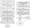
- FIG. 4 is a flowchart that illustrates the classification of blocks according to hypothesized shift ⁇ i .
- Blocks l can be divided into two categories as shown in FIG. 4 .
- the first category consists of blocks for which the modulating data bit v i ⁇ ( ( ⁇ + L ⁇ ⁇ l ) ⁇ ⁇ + ⁇ + ( f 0 + f i ) ⁇ L ⁇ ⁇ ⁇ ⁇ ⁇ l f c + ⁇ ⁇ ( j - 1 ) ) is a constant over j ⁇ [1,N].
- Such blocks are called “segments without a changing data bit.”
- step 410 of FIG. 4 it is determined whether the block straddles the data-bit boundary. If it is determined that the block does not straddles the data-bit boundary, then control passes to block 420 . Otherwise control passes to FIG. 5 herein.
- step 420 it is determined whether the data-bit changes across the boundary. If it is determined that the data-bit changes across the boundary, then control passes to FIG. 6 herein. Otherwise, control passes to FIG. 5 .
- the “floor” notation ⁇ is used to refer to the largest integer smaller than ⁇ . Or one can check that the two adjacent data bits that are straddled by the block happen to have the same value. Only if both of these conditions are false, does control pass to FIG. 5 .
- the other blocks are those for which the sign of the data bits v i ⁇ ( ( ⁇ + L ⁇ ⁇ l ) ⁇ ⁇ + ⁇ + ( f 0 + f i ) ⁇ L ⁇ ⁇ ⁇ ⁇ ⁇ l f c + ⁇ ⁇ ( j - 1 ) ) changes over j ⁇ [1,N].
- Such blocks are called “segments with a changing data bit.” For such segments, process 600 , described in FIG.
- f h ⁇ ( t ) ⁇ + 1 if ⁇ ⁇ t ⁇ ( M - h ) ⁇ ⁇ ⁇ - 1 otherwise
- FIG. 5 is a flowchart that illustrates the process for handling segments with no data bit change.
- step 522 take a time reversed block starting at 0 and duration L ⁇ of G( ⁇ i ).
- step 524 sample the result of 322 at ⁇ intervals.
- Step 526 compute its Fast Fourier Transform. (Steps 322 , 324 , and 326 can be one in advance and stored if desired since they do not depend on the x k )
- the FFT of the time reversed block from 526 should be multiplied by a block of e i ⁇ ⁇ 2 ⁇ ⁇ ⁇ N ⁇ j ⁇ ( f 0 + f i ) ⁇ L ⁇ ⁇ ⁇ ⁇ ⁇ l ⁇ ⁇ ⁇ f c where j ranges from 0 to the block length minus 1.
- This multiplication in the frequency domain corresponds to the additional code-phase delay introduced by time compression or dilation due to the Dopplers.
- the results of this multiplication can be precomputed for a variety of small (corresponding to less than the interval between samples) code-plase shifts. Any integer number of ⁇ steps left-over can be noted as ⁇ and their effect taken care of later.
- step 550 multiply the two Fourier Transforms from block 514 and 528 pointwise by each other.
- the frequency domain code-phase shift of the previous step is combined into this step since it is also a pointwise multiplication.
- step 560 multiply the resulting block from 350 by the value of the data bit v i ⁇ ( ( ⁇ + L ⁇ ⁇ l ) ⁇ ⁇ + ⁇ + ( f 0 + f i ) ⁇ L ⁇ ⁇ ⁇ ⁇ ⁇ l f c ) (This can not vary between the different ⁇ t since if it did, some of the ⁇ t would correspond to “segments with a changing data bit”)
- This complex-valued block of length N is represented by the symbol Y l .
- step 570 take the inverse Fast Fourier Transform of the resulting block Y l .
- FIG. 6 is a flowchart that illustrates the process for handling segments with a data bit change for all shift values.
- step 612 take the (y l , z l ) block viewed as N complex numbers and pad it at the end with N values of (0, 0) to get a block of length 2N.
- step 614 take the Fast Fourier Transform of this block.
- step 622 take a time reversed block starting at 0 and of duration 2L ⁇ of G ( ⁇ t f M ⁇ L ).
- step 624 sample it at ⁇ intervals. (This corresponds to a low-passed version of a PRN code followed by itself negated.)
- step 626 compute its Fast Fourier Transform. (Blocks 622 , 624 , 626 can be done in advance and stored if desired since they do not depend on the x k )
- the FFT of the time reversed block should be multiplied by a block of e i ⁇ ⁇ ⁇ N ⁇ j ⁇ ( f 0 + f i ) ⁇ L ⁇ ⁇ ⁇ ⁇ ⁇ l ⁇ ⁇ ⁇ f c corresponding to the additional delay introduced by time compression or dilation due to the Dopplers.
- this multiplication can also be precomputed for a variety of small (corresponding to less than the interval between samples) code-phase shifts.
- step 650 multiply the two Fourier Transforms pointwise by each other.
- the frequency domain code-phase shift of the previous step can be combined into this step since it is also a pointwise multiplication.
- step 660 multiply the resulting block by the value of the data bit v i at the beginning of the range of interest. (This can not vary between the different ⁇ t since if it did, some of the ⁇ i would correspond to “segments without a changing data bit”).
- This complex-valued block of length 2N is represented by the symbol Y l .
- step 670 take the inverse Fast Fourier Transform of the resulting block Y l .
- FIG. 7 is a flowchart that illustrates the process for handling segments with data bit change for some shift values.
- T ⁇ t cause the block l to be classified as a “segment without a changing data bit” while other ⁇ i values would result in classification as a “segment with a changing data bit” then classify the segment as a “segment possibly with a changing data bit” and proceed as follows.
- ⁇ is less than ⁇ ′ t,l .
- the nature of the signal is such that the explicit decision rule can be expressed as a cut by a single ⁇ ′ t,l of the hypothesized ⁇ into two regions: one in which one uses the “segment without a changing data bit” and another in which one uses the “segment with a changing data bit.”
- each spliced part might be multiplied by a different value for the data bit depending on whether the “segment with a changing data bit” portion corresponds to values for ⁇ i that are before or after the values for ⁇ t corresponding to the “segment with a changing data bit” portion.
- FIG. 8 is a flowchart that illustrates a method of increasing computational savings when dealing with a range of ⁇ t values.
- step 810 of FIG. 8 add up (pointwise) all the pre-inversion length N “segments without a changing data bit” into a new block of length N.
- step 820 take the inverse Fast Fourier Transform of the length N block Y k without and also of the length 2N blocks Y k with . Because the code-phase shifts in the frequency domain are already
- the values are read off.
- FIG. 9 is a block diagram that illustrates the basic approach of summing the (y l , z l ) blocks before the FFT of block 514 of FIG. 5 . As shown in FIG.
- the resulting blocks are then treated just like input to block 514 of FIG. 5 and are correlated with the PRN code using the FFT in block 914 .
- the difference is that in block 528 of FIG. 5 , what is needed is a code phase adjustment of multiplying by a block of e i ⁇ ⁇ 2 ⁇ ⁇ ⁇ N ⁇ j ⁇ ( f 0 + f i ) ⁇ L ⁇ ⁇ ⁇ ⁇ ⁇ ( o ⁇ ⁇ O - O 2 ) ⁇ ⁇ ⁇ f c
- the o ⁇ ⁇ O - o 2 reflects the equivalent l for this summed-block.
- the - o 2 is to center the blocks in time so that the l corresponds to the middle block composing the summed-block.
- the “segments with a changing data bit” and the “segments possibly with a changing data bit” can be dealt with in a parallel track and they can be brought all together at the end.
- the approximation loss in the above comes from not doing the code-phase-adjustments on the individual blocks before summing them up. This is usually done for computational reasons since the exact code-phase adjustments are computationally expensive to do if the signal is not already in the frequency domain. However, if O is large, then the needed code-phase adjustment can also grow large and hence the approximation gets poorer.
- Choosing a block summing size is determined by balancing a tradeoff between computational burden and accuracy of the approximation. Increasing O reduces the computational burden of the algorithm because we effectively replace taking O different FFTs with a single FFT. Similarly, O different block multiplications by the transform of the reference PRN code and code-phase-adjustments are replaced with a single such block multiplication.
- the final step of squaring and looking at the magnitude can be done for all the possibilities and the strongest peak chosen. For example, if GPS signals of duration 100 ms are considered, then there are possibly 5 sign flips giving 32 possibilities. If the time domain is used, each possibility only requires adding together two sets of 5 numbers each with possibly different signs. If the range of ⁇ t is small enough, this is not an insurmountably great computational burden. Furthermore, it is highly parallelizable.
- An embodiment of the invention may be implemented using a computer system that includes a processor for processing information.
- the Computer system also includes a main memory, such as a random access memory (RAM) or other dynamic storage device, coupled to a bus for storing information and instructions to be executed by the processor.
- the main memory also may be used for storing temporary variables or other intermediate information during execution of instructions to be executed by the processor.
- the computer system further includes a read only memory (ROM) or other static storage device coupled to the bus for storing static information and instructions for the processor.
- ROM read only memory
- a storage device such as a magnetic disk or optical disk, is provided and coupled to the bus for storing information and instructions.
- the invention is related to the use of the computer system for implementing the techniques described herein. According to one embodiment of the invention, those techniques are implemented by the computer system in response to the processor executing one or more sequences of one or more instructions contained in main memory. Such instructions may be read into the main memory from another computer-readable medium, such as the storage device. Execution of the sequences of instructions contained in the main memory causes the processor to perform the process steps described herein. One or more processors in a multi-processing arrangement may also be employed to execute the sequences of instructions contained in the main memory. In alternative embodiments, hard-wired circuitry may be used in place of or in combination with software instructions to implement the invention. Thus, embodiments of the invention are not limited to any specific combination of hardware circuitry and software.
- Non-volatile media includes, for example, optical or magnetic disks, such as the storage device.
- Volatile media includes dynamic memory, such as the main memory.
- Transmission media includes coaxial cables, copper wire and fiber optics, including the wires that comprise the bus. Transmission media can also take the form of acoustic or light waves, such as those generated during radio wave and infrared data communications.
- Computer-readable media include, for example, a floppy disk, a flexible disk, hard disk, magnetic tape, or any other magnetic medium, a CD-ROM, any other optical medium, punch cards, paper tape, any other physical medium with patterns of holes, a RAM, a PROM, and EPROM, a FLASH-EPROM, any other memory chip or cartridge, a carrier wave as described hereinafter, or any other medium from which a computer can read.
- Various forms of computer readable media may be involved in carrying one or more sequences of one or more instructions to the processor for execution.
- the instructions may initially be carried on a magnetic disk of a remote computer.
- the remote computer can load the instructions into its dynamic memory and send the instructions over a telephone line using a modem.
- a modem local to computer system can receive the data on the telephone line and use an infrared transmitter to convert the data to an infrared signal.
- An infrared detector coupled to the bus can receive the data carried in the infrared signal and place the data on the bus.
- the bus carries the data to the main memory, from which the processor retrieves and executes the instructions.
- the instructions received by the main memory may optionally be stored on the storage device either before or after execution by the processor.
- the computer system also includes a communication interface coupled to the bus.
- the communication interface provides a two-way data communication coupling to a network link that is connected to a local network.
- the communication interface may be an integrated services digital network (ISDN) card or a modem to provide a data communication connection to a corresponding type of telephone line.
- ISDN integrated services digital network
- the communication interface may be a local area network (LAN) card to provide a data communication connection to a compatible LAN.
- LAN local area network
- Wireless links may also be implemented.
- the communication interface sends and receives electrical, electromagnetic or optical signals that carry digital data streams representing various types of information.
- the network link typically provides data communication through one or more networks to other data devices.
- the network link may provide a connection through the local network to a host computer or to data equipment operated by an Internet Service Provider (ISP).
- ISP Internet Service Provider
- the ISP in turn provides data communication services through the worldwide packet data communication network now commonly referred to as the “Internet”.
- the local network and the Internet both use electrical, electromagnetic or optical signals that carry digital data streams.
- the signals through the various networks and the signals on the network link and through the communication interface, which carry the digital data to and from the computer system, are exemplary forms of carrier waves transporting the information.
- the computer system can send messages and receive data, including program code, through the network(s), the network link and the communication interface.
- a server might transmit a requested code for an application program through the Internet, the ISP, the local network and the communication interface.
- one such downloaded application implements the techniques described herein.
- the received code may be executed by the processor as it is received, and/or stored in the storage device, or other non-volatile storage for later execution.
- the computer system may obtain application code in the form of a carrier wave.
Abstract
Description
to give ξt(t).
The time is stretched or compressed to account for various factors including the properties of the receiver clock and the relative motion of the source and receiver.
is the perceived stretching or shrinking of time due to the various effects. One skilled in the art will understand that time is a quantity which only makes sense relative to clocks. The clocks at the signal source and the receiver are generally different and hence the above two reference frames have a stretching or shrinking factor of time associated with them.
Y k =x k cos(2π(f IF +f 0 +f i)Δ(k−1))
z k =x k sin (2π(f IF +f 0 +f t)Δ(k−1))
y (l,j) =y (l−1)N+j
z (l,j) =z (l−1)N+j
At
This involves using an appropriate reference function ξt for each block. To get some benefits from this approach, the (Θ, σ) representation of τt given by τi=Θtθ+σt is used and the viζi representation of ξ is used to rewrite things as:
terms, while dropping the within block
term in time. The combined effect of both these approximation is to simplify the computations while introducing only a minor error.
is a constant over j ε[1,N]. Such blocks are called “segments without a changing data bit.”
where the “floor” notation └α┘ is used to refer to the largest integer smaller than α. Or one can check that the two adjacent data bits that are straddled by the block happen to have the same value. Only if both of these conditions are false, does control pass to FIG. 5.
changes over j ε[1,N]. Such blocks are called “segments with a changing data bit.” For such segments, process 600, described in
where j ranges from 0 to the block length minus 1. This multiplication in the frequency domain corresponds to the additional code-phase delay introduced by time compression or dilation due to the Dopplers. One skilled in the art can also see that the results of this multiplication can be precomputed for a variety of small (corresponding to less than the interval between samples) code-plase shifts. Any integer number of Δ steps left-over can be noted as δ and their effect taken care of later.
can be represented as
Then at this step the shift corresponding to
can be used and the residual integer δ is dealt with at a later stage. Alternatively, the shift corresponding to
could be directly used in the frequency domain at this stage.
(This can not vary between the different τt since if it did, some of the τt would correspond to “segments with a changing data bit”) This complex-valued block of length N is represented by the symbol Yl.
corresponding to the additional delay introduced by time compression or dilation due to the Dopplers. As in the computations for the “segments without a changing data bit,” this multiplication can also be precomputed for a variety of small (corresponding to less than the interval between samples) code-phase shifts.
could be represented as
Then at this step the shift corresponding
is used.
(L−M+((Θ+Ll) mod M))θ+σ=(m−1+δ)Δ.
As in the case of “segments without a changing data bit”, there are alternative ways of dealing with δ. Overall, only N values of the inverse FFT need to be examined since the others are just inverted copies by construction.
where the (Θ, σ) correspond to the τt of interest.
Such sums need to be done only for the τt of interest and can even be done on a per-demand basis to save computational effort. One skilled in the art will see that N is chosen to be divisible by K or some standard correction is otherwise applied.
At
The
reflects the equivalent l for this summed-block. The
is to center the blocks in time so that the l corresponds to the middle block composing the summed-block.
rather than the previously given formula. As before, one skilled in the art can implement such a correction in a variety of means besides the direct frequency domain approach.
One skilled in the art can easily see how the above formula should be modified to deal with other frequencies and filters. The important thing to notice is that the amount of degradation depends on the amount of known Doppler. The higher the Doppler, the more the blurring degrades accuracy by reducing the effective SNR. It is important to remember that if one does the integer Δ code-phase adjustments above, then the residual degradation can never exceed a single Δ. The degradation estimate therefore saturates at the value for O where the shift corresponds to a single Δ.
Claims (25)
Priority Applications (1)
| Application Number | Priority Date | Filing Date | Title |
|---|---|---|---|
| US10/316,992 US6933886B1 (en) | 2001-06-22 | 2002-12-11 | Signal acquisition using data bit information |
Applications Claiming Priority (2)
| Application Number | Priority Date | Filing Date | Title |
|---|---|---|---|
| US09/888,228 US6512479B1 (en) | 2001-06-22 | 2001-06-22 | Signal acquisition using data bit information |
| US10/316,992 US6933886B1 (en) | 2001-06-22 | 2002-12-11 | Signal acquisition using data bit information |
Related Parent Applications (1)
| Application Number | Title | Priority Date | Filing Date |
|---|---|---|---|
| US09/888,228 Continuation US6512479B1 (en) | 2001-06-22 | 2001-06-22 | Signal acquisition using data bit information |
Publications (1)
| Publication Number | Publication Date |
|---|---|
| US6933886B1 true US6933886B1 (en) | 2005-08-23 |
Family
ID=25392794
Family Applications (2)
| Application Number | Title | Priority Date | Filing Date |
|---|---|---|---|
| US09/888,228 Expired - Lifetime US6512479B1 (en) | 2001-06-22 | 2001-06-22 | Signal acquisition using data bit information |
| US10/316,992 Expired - Lifetime US6933886B1 (en) | 2001-06-22 | 2002-12-11 | Signal acquisition using data bit information |
Family Applications Before (1)
| Application Number | Title | Priority Date | Filing Date |
|---|---|---|---|
| US09/888,228 Expired - Lifetime US6512479B1 (en) | 2001-06-22 | 2001-06-22 | Signal acquisition using data bit information |
Country Status (4)
| Country | Link |
|---|---|
| US (2) | US6512479B1 (en) |
| EP (1) | EP1407285A2 (en) |
| AU (1) | AU2002345812A1 (en) |
| WO (1) | WO2003001230A2 (en) |
Cited By (8)
| Publication number | Priority date | Publication date | Assignee | Title |
|---|---|---|---|---|
| US20060209932A1 (en) * | 2005-03-18 | 2006-09-21 | Qualcomm Incorporated | Channel estimation for single-carrier systems |
| US20070076788A1 (en) * | 2005-10-04 | 2007-04-05 | Zhike Jia | Bit synchronization for weak navigational satellite signals |
| US20070183487A1 (en) * | 2005-12-21 | 2007-08-09 | Nemerix Sa | Optimal use of resources for signal processors |
| US20070230543A1 (en) * | 2005-10-04 | 2007-10-04 | Zhike Jia | Data demodulation from weak navigational satellite signals |
| WO2009024184A1 (en) | 2007-08-21 | 2009-02-26 | Telecom Italia S.P.A. | Method for the acquisition of signals of a global navigation satellite system |
| US20090251364A1 (en) * | 2008-04-03 | 2009-10-08 | Beceem Communications Inc. | Method and system of a mobile subscriber estimating position |
| US20120100799A1 (en) * | 2010-10-25 | 2012-04-26 | Seiko Epson Corporation | Method of determining reliability of received signal, method of calculating code phase error, and apparatus for determining reliability of received signal |
| WO2020096698A3 (en) * | 2018-09-26 | 2020-07-30 | Qualcomm Incorporated | Satellite positioning system navigation bit aiding |
Families Citing this family (7)
| Publication number | Priority date | Publication date | Assignee | Title |
|---|---|---|---|---|
| US6512479B1 (en) * | 2001-06-22 | 2003-01-28 | Enuvis, Inc. | Signal acquisition using data bit information |
| US7069019B2 (en) * | 2001-09-08 | 2006-06-27 | Sirf Technology, Inc. | System and method to estimate the location of a receiver |
| US6725157B1 (en) * | 2002-06-10 | 2004-04-20 | Trimble Navigation Limited | Indoor GPS clock |
| US7187736B2 (en) * | 2003-02-13 | 2007-03-06 | Motorola Inc. | Reducing interference in a GSM communication system |
| KR100587167B1 (en) * | 2003-12-19 | 2006-06-08 | 삼성전자주식회사 | Method of detecting bit boundary and apparatus for performing the same, method of discriminating receipt of a satellite signal and apparatus for performing the same |
| US7917362B2 (en) * | 2006-04-19 | 2011-03-29 | Mediatek Inc. | Method and apparatus for determining a bit boundary of a repetition-coded signal |
| US11630217B2 (en) * | 2019-05-21 | 2023-04-18 | Deere & Company | Methods and devices for global navigation satellite system (GNSS) signal acquisition |
Citations (8)
| Publication number | Priority date | Publication date | Assignee | Title |
|---|---|---|---|---|
| US4701934A (en) * | 1985-09-03 | 1987-10-20 | Motorola, Inc. | Method of doppler searching in a digital GPS receiver |
| US5663734A (en) | 1995-10-09 | 1997-09-02 | Precision Tracking, Inc. | GPS receiver and method for processing GPS signals |
| US5884214A (en) | 1996-09-06 | 1999-03-16 | Snaptrack, Inc. | GPS receiver and method for processing GPS signals |
| US6078286A (en) * | 1998-06-03 | 2000-06-20 | Motorola, Inc. | Method and apparatus for efficient acquisition and tracking of satellites |
| US6133874A (en) * | 1996-03-08 | 2000-10-17 | Snaptrack, Inc. | Method and apparatus for acquiring satellite positioning system signals |
| US6327473B1 (en) * | 1998-09-08 | 2001-12-04 | Qualcomm Incorporated | Method and apparatus for increasing the sensitivity of a global positioning satellite receiver |
| US6392593B1 (en) * | 2000-05-08 | 2002-05-21 | Garmin Corporation | Time division satellite acquisition |
| US6512479B1 (en) * | 2001-06-22 | 2003-01-28 | Enuvis, Inc. | Signal acquisition using data bit information |
Family Cites Families (6)
| Publication number | Priority date | Publication date | Assignee | Title |
|---|---|---|---|---|
| US5420592A (en) * | 1993-04-05 | 1995-05-30 | Radix Technologies, Inc. | Separated GPS sensor and processing system for remote GPS sensing and centralized ground station processing for remote mobile position and velocity determinations |
| US6232922B1 (en) * | 1998-05-12 | 2001-05-15 | Mcintosh John C. | Passive three dimensional track of non-cooperative targets through opportunistic use of global positioning system (GPS) and GLONASS signals |
| US6195041B1 (en) * | 1998-09-09 | 2001-02-27 | Qualcomm Incorporated | Reliable position location in memory limited environment |
| US6297770B1 (en) * | 2000-05-23 | 2001-10-02 | Mitsubishi Denki Kabushiki Kaisha | Global positioning system and global positioning method with improved sensitivity by detecting navigation data inversion boundaries |
| JP3270407B2 (en) * | 1998-12-28 | 2002-04-02 | 三菱電機株式会社 | GPS positioning method, GPS terminal and GPS positioning system |
| US6577271B1 (en) * | 1999-03-30 | 2003-06-10 | Sirf Technology, Inc | Signal detector employing coherent integration |
-
2001
- 2001-06-22 US US09/888,228 patent/US6512479B1/en not_active Expired - Lifetime
-
2002
- 2002-06-21 EP EP02744559A patent/EP1407285A2/en not_active Withdrawn
- 2002-06-21 AU AU2002345812A patent/AU2002345812A1/en not_active Abandoned
- 2002-06-21 WO PCT/US2002/019894 patent/WO2003001230A2/en not_active Application Discontinuation
- 2002-12-11 US US10/316,992 patent/US6933886B1/en not_active Expired - Lifetime
Patent Citations (10)
| Publication number | Priority date | Publication date | Assignee | Title |
|---|---|---|---|---|
| US4701934A (en) * | 1985-09-03 | 1987-10-20 | Motorola, Inc. | Method of doppler searching in a digital GPS receiver |
| US5663734A (en) | 1995-10-09 | 1997-09-02 | Precision Tracking, Inc. | GPS receiver and method for processing GPS signals |
| US5781156A (en) | 1995-10-09 | 1998-07-14 | Snaptrack, Inc. | GPS receiver and method for processing GPS signals |
| US6133874A (en) * | 1996-03-08 | 2000-10-17 | Snaptrack, Inc. | Method and apparatus for acquiring satellite positioning system signals |
| US5884214A (en) | 1996-09-06 | 1999-03-16 | Snaptrack, Inc. | GPS receiver and method for processing GPS signals |
| US6272430B1 (en) | 1996-09-06 | 2001-08-07 | Snaptrack, Inc. | GPS receiver and method for processing GPS signals |
| US6078286A (en) * | 1998-06-03 | 2000-06-20 | Motorola, Inc. | Method and apparatus for efficient acquisition and tracking of satellites |
| US6327473B1 (en) * | 1998-09-08 | 2001-12-04 | Qualcomm Incorporated | Method and apparatus for increasing the sensitivity of a global positioning satellite receiver |
| US6392593B1 (en) * | 2000-05-08 | 2002-05-21 | Garmin Corporation | Time division satellite acquisition |
| US6512479B1 (en) * | 2001-06-22 | 2003-01-28 | Enuvis, Inc. | Signal acquisition using data bit information |
Non-Patent Citations (4)
| Title |
|---|
| A. J. R. M. Coenen and D. J. R. Van Nee, "Novel Fast GPS/Glonass Code-Acquisition Technique Using Low Update Rate FFT" -Electronics Letters, Apr. 23, 1992, vol. 28, No. 9. |
| D. J. R. Van Nee and A. J. R. M. Coenen, "New Fast GPS Code-Acquisition Technique Using FFT"-(publication) Telecommunications and Traffic-control Systems Group, Delft University of Technology, The Netherlands, Nov. 23, 1990. |
| Psiaki, Mark L., "Block Acquisition of Weak GPS Signals in a Software Receiver," Cornell University Presented at ION GPS 2001, Sep. 11-14, 2001, Salt Lake City, pp. 1-13. |
| Tsui, James Bao-Yen, "Fundamentals of Global Positioning System Receivers: A Software Approach," Wiley, 2000, pp. 149-150. |
Cited By (17)
| Publication number | Priority date | Publication date | Assignee | Title |
|---|---|---|---|---|
| US20060209932A1 (en) * | 2005-03-18 | 2006-09-21 | Qualcomm Incorporated | Channel estimation for single-carrier systems |
| US7660373B2 (en) * | 2005-10-04 | 2010-02-09 | Sirf Technology, Inc. | Data demodulation from weak navigational satellite signals |
| US20070076788A1 (en) * | 2005-10-04 | 2007-04-05 | Zhike Jia | Bit synchronization for weak navigational satellite signals |
| US20070230543A1 (en) * | 2005-10-04 | 2007-10-04 | Zhike Jia | Data demodulation from weak navigational satellite signals |
| US7778311B2 (en) | 2005-10-04 | 2010-08-17 | Sirf Technology Holdings, Inc. | Bit synchronization for weak navigational satellite signals |
| US20070183487A1 (en) * | 2005-12-21 | 2007-08-09 | Nemerix Sa | Optimal use of resources for signal processors |
| US7903719B2 (en) | 2005-12-21 | 2011-03-08 | Qualcomm Incorporated | Optimal use of resources for signal processors |
| US20100141520A1 (en) * | 2007-08-21 | 2010-06-10 | Giorgio Ghinamo | Method for the acquisition of signals of a global navigation satellite system |
| WO2009024184A1 (en) | 2007-08-21 | 2009-02-26 | Telecom Italia S.P.A. | Method for the acquisition of signals of a global navigation satellite system |
| US8179311B2 (en) | 2007-08-21 | 2012-05-15 | Telecom Italia S.P.A. | Method for the acquisition of signals of a global navigation satellite system |
| CN101821643B (en) * | 2007-08-21 | 2013-02-20 | 意大利电信股份公司 | Method for the acquisition of signals of a global navigation satellite system and receiver thereof |
| US7602334B1 (en) | 2008-04-03 | 2009-10-13 | Beceem Communications Inc. | Method and system of a mobile subscriber estimating position |
| US20090251364A1 (en) * | 2008-04-03 | 2009-10-08 | Beceem Communications Inc. | Method and system of a mobile subscriber estimating position |
| US20120100799A1 (en) * | 2010-10-25 | 2012-04-26 | Seiko Epson Corporation | Method of determining reliability of received signal, method of calculating code phase error, and apparatus for determining reliability of received signal |
| US8849192B2 (en) * | 2010-10-25 | 2014-09-30 | Seiko Epson Corporation | Method of determining reliability of received signal, method of calculating code phase error, and apparatus for determining reliability of received signal |
| WO2020096698A3 (en) * | 2018-09-26 | 2020-07-30 | Qualcomm Incorporated | Satellite positioning system navigation bit aiding |
| US10845486B2 (en) | 2018-09-26 | 2020-11-24 | Qualcomm Incorporated | Satellite positioning system navigation bit aiding |
Also Published As
| Publication number | Publication date |
|---|---|
| AU2002345812A1 (en) | 2003-01-08 |
| US6512479B1 (en) | 2003-01-28 |
| EP1407285A2 (en) | 2004-04-14 |
| WO2003001230A3 (en) | 2004-02-12 |
| WO2003001230B1 (en) | 2004-04-15 |
| WO2003001230A2 (en) | 2003-01-03 |
Similar Documents
| Publication | Publication Date | Title |
|---|---|---|
| US6933886B1 (en) | Signal acquisition using data bit information | |
| CN101099089B (en) | Method and apparatus for increasing coherent integration length while receiving positioning signal | |
| US7272168B2 (en) | Determining the correlation between received samples and available replica samples | |
| CN1106617C (en) | Low power parallel correlator for measuring correlation between digital signal segments | |
| US6922546B1 (en) | GPS signal acquisition based on frequency-domain and time-domain processing | |
| CN1130844C (en) | Method for efficient sampling in a correlator | |
| US7920093B2 (en) | Methods for improving computational efficiency in a global positioning satellite receiver | |
| US20070105502A1 (en) | Narrowband noise mitigation in location-determining signal processing | |
| CN1225174A (en) | Power efficient receiver | |
| US8830123B2 (en) | Satellite navigation system for optimal time to first fix using code and carrier diversity | |
| CN104977593B (en) | Radio communication synchronization system | |
| EP1419401B1 (en) | System and method to determine the location of a receiver | |
| CN1225208A (en) | Method for doppler-replica harmonic avoidance in a GPS receiver | |
| CN1458746A (en) | Method system and electronic device for synchronizing receiver | |
| US20090052506A1 (en) | Acquisition of a Code Modulated Signal | |
| Gao et al. | Code generation scheme and property analysis of broadcast Galileo L1 and E6 signals | |
| US7027534B2 (en) | Extracting fine-tuned estimates from correlation functions evaluated at a limited number of values | |
| US20040141574A1 (en) | Determination of the code phase between a code modulated signal and a replica code sequence | |
| US7277476B2 (en) | Determining the correlation between received samples and available replica samples | |
| US20100135363A1 (en) | Supporting a Signal Acquisition | |
| US7286594B2 (en) | Determination of the correlation phase between a signal and a replica sequence | |
| CA2350006A1 (en) | A method of aligning predicted navigation information | |
| Zhang | An Optimized acquisition scheme with half interleaving code patterns in a QZSS LEX single frequency receiver | |
| Aktas | Time difference of arrival (TDOA) estimation using wavelet based denoising | |
| US6642885B2 (en) | Receiver for a satellite based position location system |
Legal Events
| Date | Code | Title | Description |
|---|---|---|---|
| STCF | Information on status: patent grant |
Free format text: PATENTED CASE |
|
| AS | Assignment |
Owner name: SIRF TECHNOLOGY, INC., CALIFORNIA Free format text: ASSIGNMENT OF ASSIGNORS INTEREST;ASSIGNOR:SIRF TECHNOLOGY HOLDINGS, INC.;REEL/FRAME:017663/0053 Effective date: 20060522 |
|
| FEPP | Fee payment procedure |
Free format text: PAT HOLDER NO LONGER CLAIMS SMALL ENTITY STATUS, ENTITY STATUS SET TO UNDISCOUNTED (ORIGINAL EVENT CODE: STOL); ENTITY STATUS OF PATENT OWNER: LARGE ENTITY |
|
| FPAY | Fee payment |
Year of fee payment: 4 |
|
| AS | Assignment |
Owner name: CSR TECHNOLOGY INC., CALIFORNIA Free format text: CHANGE OF NAME;ASSIGNOR:SIRF TECHNOLOGY, INC.;REEL/FRAME:026067/0569 Effective date: 20101119 |
|
| FPAY | Fee payment |
Year of fee payment: 8 |
|
| AS | Assignment |
Owner name: ENUVIS, INC., CALIFORNIA Free format text: MERGER;ASSIGNOR:SIRF ACQUISITION CORP.;REEL/FRAME:038205/0946 Effective date: 20030328 Owner name: CSR TECHNOLOGY HOLDINGS, INC., CALIFORNIA Free format text: MERGER;ASSIGNOR:ENUVIS, INC.;REEL/FRAME:038206/0033 Effective date: 20130925 Owner name: ENUVIS, INC., CALIFORNIA Free format text: ASSIGNMENT OF ASSIGNORS INTEREST;ASSIGNORS:SAHAI, ANANT;MANN, WALLACE;CHOU, ANDREW;AND OTHERS;REEL/FRAME:038205/0891 Effective date: 20011011 |
|
| FPAY | Fee payment |
Year of fee payment: 12 |