US6853333B2 - Downlink load sharing by beam selection - Google Patents
Downlink load sharing by beam selection Download PDFInfo
- Publication number
- US6853333B2 US6853333B2 US10/661,883 US66188303A US6853333B2 US 6853333 B2 US6853333 B2 US 6853333B2 US 66188303 A US66188303 A US 66188303A US 6853333 B2 US6853333 B2 US 6853333B2
- Authority
- US
- United States
- Prior art keywords
- user
- interference
- users
- information
- main lobe
- Prior art date
- Legal status (The legal status is an assumption and is not a legal conclusion. Google has not performed a legal analysis and makes no representation as to the accuracy of the status listed.)
- Expired - Lifetime
Links
Images


Classifications
-
- H—ELECTRICITY
- H04—ELECTRIC COMMUNICATION TECHNIQUE
- H04W—WIRELESS COMMUNICATION NETWORKS
- H04W16/00—Network planning, e.g. coverage or traffic planning tools; Network deployment, e.g. resource partitioning or cells structures
- H04W16/24—Cell structures
- H04W16/28—Cell structures using beam steering
-
- H—ELECTRICITY
- H01—ELECTRIC ELEMENTS
- H01Q—ANTENNAS, i.e. RADIO AERIALS
- H01Q1/00—Details of, or arrangements associated with, antennas
- H01Q1/12—Supports; Mounting means
- H01Q1/22—Supports; Mounting means by structural association with other equipment or articles
- H01Q1/24—Supports; Mounting means by structural association with other equipment or articles with receiving set
- H01Q1/241—Supports; Mounting means by structural association with other equipment or articles with receiving set used in mobile communications, e.g. GSM
- H01Q1/246—Supports; Mounting means by structural association with other equipment or articles with receiving set used in mobile communications, e.g. GSM specially adapted for base stations
-
- H—ELECTRICITY
- H01—ELECTRIC ELEMENTS
- H01Q—ANTENNAS, i.e. RADIO AERIALS
- H01Q3/00—Arrangements for changing or varying the orientation or the shape of the directional pattern of the waves radiated from an antenna or antenna system
- H01Q3/26—Arrangements for changing or varying the orientation or the shape of the directional pattern of the waves radiated from an antenna or antenna system varying the relative phase or relative amplitude of energisation between two or more active radiating elements; varying the distribution of energy across a radiating aperture
- H01Q3/2605—Array of radiating elements provided with a feedback control over the element weights, e.g. adaptive arrays
-
- H—ELECTRICITY
- H04—ELECTRIC COMMUNICATION TECHNIQUE
- H04W—WIRELESS COMMUNICATION NETWORKS
- H04W36/00—Hand-off or reselection arrangements
- H04W36/06—Reselecting a communication resource in the serving access point
Definitions
- the invention relates generally to antenna communications and, more particularly, to multi-beam antenna systems.
- RRM radio resource management
- load control is especially important. It maintains system stability and a reasonable link quality level for existing users. If too many users are admitted to a cell, party effects may occur. This will lead to extensive dropping of users in the cell. Also, neighboring cells may also be affected if the inter cell interference is high. Load Control prevents this and maintains system stability.
- Common for most load control algorithms is that they set a threshold of the usage of a scarce resource.
- the scarce resource can be an estimate of power (link or total base station transmit), codes, number of users, throughput, SIR based (e.g. the sum of all users' SIR) and interference level or a combination of these.
- the estimate can be local (only considering estimates from the associated cell) or can also consider estimates from neighboring sites. The algorithm then admits users as long as the estimate of the scarce resource is not exceeding the threshold.
- AA adaptive antenna
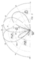
- FIG. 1 shows an example of how the antenna diagram may look for an adaptive antenna system.
- the C/I is increased and in the downlink the interference is suppressed.
- capacity is gained.
- the inventors have found that in most cases the majority of the downlink interference of a fixed (or steered) multi-beam system for a speech only scenario originates from the main lobe. For example, most of the interference seen by a user connected to the main lobe of beam A in FIG. 1 originates from other users also connected to the main lobe of beam A. However, some sources of interference do not originate from the main lobe of the beam. Examples of such “external” interference sources include:
- this external interference typically accounts for only a small part of the total interference for each user.
- the interference from other cells can be substantial.
- third generation systems will include not only speech users, but rather a mix of many different services, such as video, web browsing, file transfers and other such high data rate (HDR) services.
- HDR high data rate
- the inventors have found that the interference from high data rate users outside the main lobe may be substantial in spite of the attenuation between the sidelobe and main lobe. This is because of either a sidelobe or an overlapping beam area. A high data rate user that interferes substantially with the adjacent main lobe of a beam may cause a congestion problem.
- each beam direction can handle at maximum an equivalent of M speech users.
- an admission control that operates on per beam direction.
- the admission control admits up to the maximum level of M users into the beam direction. This can be done e.g., by checking both the number of equivalent speech users “connected” to the beam and/or the interference load on the beam.
- a high data rate user is admitted access to beam B.
- the total load in beam B equals exactly M equivalent speech users.
- the high data rate user connected to beam B moves into the side lobe of beam A it will be affected by the transmit power from the speech users from beam A.
- the HDR user will experience increased interference.
- the high data rate user must increase its required transmit power due to the new increased interference from the speech users in beam A.
- the increased transmit power from the high data rate user will in turn affect all other users “connected” or adjacent to beam B.
- the increased transmit power from the HDR will increase the interference for all users “connected to” or adjacent to beam B.
- beam B now has M+N1 equivalent speech users. This will very likely result in a very severe and non-acceptable quality problem and a sharp increase of required power from the users, which will lower the total system capacity.
- the invention exploits the situation wherein the load/interference from an angular perspective is not equal within a cell, and spreads the interference more equally within the cell. This is achieved by judicious use of at least one of nulling, beam steering and beam selection.
- the load/interference spreading decreases the load in highly loaded areas/directions and increases the load in less heavily loaded areas/directions.
- the nulling, beam steering and beam selection operations are applicable to coherent adaptive antenna systems, and the beam selection technique is also applicable to fixed beam systems.
- FIG. 1 is an antenna diagram of an exemplary adaptive antenna arrangement with three beams.
- FIG. 2 is an antenna diagram similar to FIG. 1 , illustrating an interference problem associated with the arrangement of FIG. 1 .
- FIG. 3 is an antenna diagram similar to FIG. 1 , illustrating exemplary nulling and beam steering operations according to the invention.
- FIG. 4 illustrates exemplary nulling and beam steering operations according to the invention.
- FIG. 5 illustrates further exemplary beam steering operations according to the invention.
- FIG. 6 taken in conjunction with FIG. 5 , illustrates further exemplary nulling and beam steering operations according to the invention.
- FIG. 7 taken in conjunction with FIG. 5 , illustrates further exemplary nulling and beam steering operations according to the invention.
- FIG. 8 diagrammatically illustrates pertinent portions of exemplary embodiments of a base station according to the invention that utilizes a steered, multi-beam antenna arrangement.
- FIG. 9 illustrates exemplary beam selection operations according to the invention.
- FIG. 10 diagrammatically illustrates pertinent portions of exemplary embodiments of a base station according to the invention that utilizes a multi-beam antenna arrangement.
- FIG. 11 illustrates exemplary beam selection operations according to the invention.
- a conventional FB system transmits in the beam where most power is received during uplink (UL) transmission. Even though this is optimal for each user, it may not be the best for the overall system. This fact is exploited by the present invention. Due to interference power from overlapping beams or power “leakage” through side lobes, a high data rate (HDR) user may cause much interference to other highly loaded beams and hence cause serious trouble for users allocated to that beam. It does not necessarily need to be a HDR user, any type of user employing high transmit power may cause serious trouble, but is likely to be a HDR user because it generally requires more transmit power than, for example, a speech user, due to its high data rate.
- HDR high data rate
- any type of user transmitting with high power and causing high interference for other users for example, a speech user with an unusually high QoS requirement, is also considered to be an HDR user as that term is used herein.
- the antenna diagram of this new beam may overlap with the beam where the most UL power is received.
- the new beam can have at least some UL received power from the UL transmission of the user.
- a coherent system with “flexible” beamforming there are more possibilities than for a FB system.
- the pointing direction can be changed but also the shape of the beam, e.g. nulls can be generated and steered towards other users.
- an HDR user can cause trouble to other users since the high power intended for this HDR user also will hit others due to the beam-width of the main lobe or through side lobe “leakage”.
- the HDR user can point an antenna null towards the interfered user and hence not transmit any power toward that direction (of the interfered user).
- this can be accomplished by using conventional techniques to change the side conditions when determining the antenna weights for this user.
- This can be thought of as an ordinary filter where it is possible to change the frequency (here directions) of the stop/pass-band of the filter.
- information from other users e.g., their quality and direction, can be used in an attempt to relieve the situation for a highly disturbed user.
- One general idea of the invention is to use this beamforming flexibility of coherent systems not necessarily to optimize the link towards each user (which is the conventional way of using AA), but instead to optimize the overall performance of the system by utilizing the radio resource management in conjunction with AA.
- a base station e.g. for WCDMA cellular telephony
- L antenna elements covering the cell area.
- For each antenna array i.e., a cell area it is possible to create a maximum L ⁇ 1 nulls towards other users/interferers.
- a nulling mechanism can cause, for example, a beam (or beams) in a direction (or directions) adjacent the high load direction to direct nulls toward the highly loaded area.
- the amount of loading in a given direction can be determined in any desired manner, such as from the interference in the uplink, TPC commands, an SIR target increase, received power at the base station, transmit power from the base station, etc.
- the nulled energy will appear in the antenna diagram somewhere else. In some embodiments, this nulled energy can be “steered” to a beam with low loading, perhaps beam C.
- FIG. 3 shows an example of this.
- Beam A directs null toward the HDR user in beam B.
- FIG. 3 shows how the antenna diagram can look like after nulling of the sidelobe.
- the sidelobe energy of beam A appears in beam C, which is assumed (for this example) to have low loading.
- Another exemplary embodiment of the invention steers the main lobes. Assume the main lobes of beams A and B are angularly separated, but overlap each other as shown in FIG. 3 . Further assume that users connected to beam A have difficulty maintaining the negotiated quality (e.g. bit rate, FER, delay) due to a considerably high interference/load situation, while users connected to beam B have no problems at all due to low interference/loading. By steering beam B's main lobe away from the main lobe of beam A, the interference may be lowered for users connected to beam A. Beam B will of course need to increase its power consumption due to the non-optimal beam direction that results from steering beam B away from its current position. This shares (distributes) the load over the cell. In some embodiments, this load sharing by beam steering will only take place if it is certain that beam B can still maintain the required quality level after being steered away from beam A (i.e., only if beam B has relatively low interference/loading).
- FER bit rate
- any adjacent beam with low load may be used for transmission to the HDR user, e.g. beam C in this example.
- FIG. 4 illustrates exemplary operations according to the present invention.
- the invention identifies a beam whose main lobe is overloaded.
- any suitable interference/loading indicator can be utilized, for example one of the indicators mentioned above.
- the overloaded condition can be determined by comparing a selected interference/loading indicator to a corresponding threshold.
- the threshold can be determined, for example, empirically based on experimentation/simulation under expected operating conditions and in view of desired performance. (All overload and underload conditions described herein can be determined, for example, in this same general fashion.)
- the null(s) of one or more other (e.g. adjacent) beams is/are steered in the main lobe direction of the overloaded beam.
- the sidelobe(s) of the one or more other beams is/are steered in the main lobe direction(s) of one or more underloaded beams.
- An underloaded beam can be, for example, a beam with more available communication capacity than the main lobe of the overloaded beam.
- any suitable interference/loading indicator can be used for the underloaded determination, and a suitable threshold can be empirically determined from experimentation/simulation in generally the same manner described above.
- FIG. 5 illustrates further exemplary operations according to the invention.
- a beam having an overloaded main lobe is identified, together with one or more beams whose main lobe(s) overlap the main lobe of the overloaded beam. It is determined at 52 whether the main lobe of any of the overlapping beams is underloaded. If not, operations return to 51 . Otherwise, the main lobe(s) of the underloaded, overlapping beam(s) is/are steered away from the main lobe of the overloaded beam at 53 .
- FIG. 6 taken together with FIG. 5 , illustrates further exemplary operations according to the invention.
- the null(s) of the overlapping beam(s) is/are steered at 61 in the main lobe direction of the overloaded beam.
- operations return to 51 in FIG. 5 .
- the sidelobe(s) of the overlapping beam(s) is/are steered at 62 in the main lobe direction(s) of one or more underloaded beam(s).
- FIG. 7 taken together with FIG. 5 , illustrates further exemplary operations according to the invention.
- the null(s) of the underloaded, overlapping beam(s) is/are steered at 71 in the main lobe direction of the overloaded beam.
- operations return to 51 in FIG. 3 .
- the sidelobe(s) of the underloaded, overlapping beam(s) is/are steered at 72 in the direction(s) of the main lobe(s) of one or more further underloaded beams.
- the threshold level used to make the underloaded determination at 52 in FIG. 5 is a lower level of interference/loading than the threshold level used to make the underloaded determination at 43 , 62 and 72 in FIGS. 4 , 6 and 7 , respectively.
- the threshold level used to make the underloaded determination can, in such embodiments, be set low enough to permit a margin of safety with respect to the communication quality associated with the beam after the re-positioning of the beam.
- FIG. 8 diagrammatically illustrates pertinent portions of exemplary embodiments of a base station (e.g. for CDMA or WCDMA cellular telephony) according to the invention, including a steerable multi-beam antenna arrangement (e.g., a coherent system) capable of producing beam patterns such as illustrated generally in FIGS. 1-3 .
- the base station of FIG. 8 includes steering logic 81 for performing operations illustrated in FIGS. 4-7 in response to loading information received at an input 82 and threshold information received at an input 83 .
- the steering logic 81 outputs a signal 84 to a steering mechanism of the antenna arrangement.
- the signal 84 is indicative of the desired steering (including nulling) operation(s), and the steering mechanism 85 can use conventional techniques to steer the antenna array 86 as instructed by the signal 84 .
- FIG. 9 illustrates further exemplary operations according to the invention.
- a first beam whose main lobe is overloaded is identified.
- an HDR user in an area covered by the main lobe of a second beam adjacent or overlapping the first beam is identified.
- a further beam whose main lobe is underloaded e.g. has more available communication capacity than the main lobe of the first beam is selected for communication with the HDR user.
- FIG. 11 illustrates further exemplary operations according to the invention.
- an HDR user is identified in an area covered by a first beam whose main lobe is overloaded.
- a second beam that is adjacent or overlapping the first beam, and whose main lobe is underloaded is selected for communication with the HDR user.
- FIG. 10 diagrammatically illustrates pertinent portions of a base station (e.g. for CDMA or WCDMA cellular telephony) according to the invention, including a multi-beam antenna arrangement (e.g., an FB system or a coherent system) capable of producing beam patterns such as illustrated generally in FIGS. 1-3 .
- selection logic 101 receives loading information at input 102 and HDR user information at input 103 .
- the HDR user information includes information which identifies the user as an HDR user, and also identifies the area of the cell in which the HDR user is currently located. Such HDR user information is readily available in conventional cellular communication systems.
- the selection logic 101 also has an input 104 for receiving threshold information for use in making the underloaded and overloaded determinations of FIG.
- the selection logic 101 has an output 105 coupled to a user-to-beam correlation database or look-up table 106 .
- the selection logic 101 can perform the exemplary operations of FIG. 9 or 11 and update the database 106 to reflect the beam to which the HDR user has been assigned by operation of the selection logic 101 .
- a communication control portion of the base station can utilize the database 106 in conventional fashion such that communication with a given HDR user is carried out via the beam that the selection logic 101 has selected for that HDR user.
- embodiments that utilize a coherent adaptive antenna system can include the selection logic 101 and the steering logic 81 of FIG. 8 , thereby permitting beam selection operation and/or nulling/steering operation.
- FIGS. 1-10 can be readily implemented, for example, by suitably modifying software, hardware or a combination of software and hardware in conventional base stations which utilize multi-beam antenna arrangements, for example multi-beam CDMA or WCDMA base stations.
Abstract
Description
Claims (12)
Priority Applications (1)
| Application Number | Priority Date | Filing Date | Title |
|---|---|---|---|
| US10/661,883 US6853333B2 (en) | 2001-11-20 | 2003-09-12 | Downlink load sharing by beam selection |
Applications Claiming Priority (3)
| Application Number | Priority Date | Filing Date | Title |
|---|---|---|---|
| US33166601P | 2001-11-20 | 2001-11-20 | |
| US10/185,746 US6667712B2 (en) | 2001-11-20 | 2002-06-28 | Downlink load sharing by nulling, beam steering and beam selection |
| US10/661,883 US6853333B2 (en) | 2001-11-20 | 2003-09-12 | Downlink load sharing by beam selection |
Related Parent Applications (1)
| Application Number | Title | Priority Date | Filing Date |
|---|---|---|---|
| US10/185,746 Division US6667712B2 (en) | 2001-11-20 | 2002-06-28 | Downlink load sharing by nulling, beam steering and beam selection |
Publications (2)
| Publication Number | Publication Date |
|---|---|
| US20040056795A1 US20040056795A1 (en) | 2004-03-25 |
| US6853333B2 true US6853333B2 (en) | 2005-02-08 |
Family
ID=26881429
Family Applications (2)
| Application Number | Title | Priority Date | Filing Date |
|---|---|---|---|
| US10/185,746 Expired - Lifetime US6667712B2 (en) | 2001-11-20 | 2002-06-28 | Downlink load sharing by nulling, beam steering and beam selection |
| US10/661,883 Expired - Lifetime US6853333B2 (en) | 2001-11-20 | 2003-09-12 | Downlink load sharing by beam selection |
Family Applications Before (1)
| Application Number | Title | Priority Date | Filing Date |
|---|---|---|---|
| US10/185,746 Expired - Lifetime US6667712B2 (en) | 2001-11-20 | 2002-06-28 | Downlink load sharing by nulling, beam steering and beam selection |
Country Status (4)
| Country | Link |
|---|---|
| US (2) | US6667712B2 (en) |
| EP (1) | EP1449398A1 (en) |
| AU (1) | AU2002349852A1 (en) |
| WO (1) | WO2003045093A1 (en) |
Cited By (3)
| Publication number | Priority date | Publication date | Assignee | Title |
|---|---|---|---|---|
| WO2012142876A1 (en) | 2011-04-22 | 2012-10-26 | Telefonaktiebolaget L M Ericsson (Publ) | Intra-frequency load balancing method and apparatus thereof |
| US10009085B2 (en) | 2002-11-04 | 2018-06-26 | Xr Communications, Llc | Directed wireless communication |
| WO2023225074A1 (en) * | 2022-05-17 | 2023-11-23 | Cohere Technologies, Inc. | Spatial diversity measurement, tracking and management |
Families Citing this family (67)
| Publication number | Priority date | Publication date | Assignee | Title |
|---|---|---|---|---|
| US6667712B2 (en) * | 2001-11-20 | 2003-12-23 | Telefonaktiebolaget Lm Ericsson (Publ) | Downlink load sharing by nulling, beam steering and beam selection |
| US7146170B2 (en) * | 2002-12-10 | 2006-12-05 | Andrew Corp. | Wireless network management system |
| JP2004248162A (en) * | 2003-02-17 | 2004-09-02 | Kyocera Corp | Base station device |
| EP1843485B1 (en) | 2006-03-30 | 2016-06-08 | Sony Deutschland Gmbh | Multiple-input multiple-output (MIMO) spatial multiplexing system with dynamic antenna beam combination selection capability |
| JP4138825B2 (en) * | 2006-07-26 | 2008-08-27 | 株式会社東芝 | Weight calculation method, weight calculation device, adaptive array antenna, and radar device |
| US8254843B2 (en) * | 2006-12-11 | 2012-08-28 | The Boeing Company | Method for pointing high-gain antennas to reduce interference in mobile networks |
| US20090023477A1 (en) * | 2007-07-19 | 2009-01-22 | Telefonaktiebolaget Lm Ericsson (Publ) | Method and apparatus for reconfiguring a multi-sector base station |
| US20090160638A1 (en) * | 2007-12-20 | 2009-06-25 | 3M Innovative Properties Company | Radio frequency identification reader system |
| US9196157B2 (en) | 2010-02-25 | 2015-11-24 | AT&T Mobolity II LLC | Transportation analytics employing timed fingerprint location information |
| US9008684B2 (en) | 2010-02-25 | 2015-04-14 | At&T Mobility Ii Llc | Sharing timed fingerprint location information |
| US9053513B2 (en) | 2010-02-25 | 2015-06-09 | At&T Mobility Ii Llc | Fraud analysis for a location aware transaction |
| US8736484B2 (en) * | 2010-08-11 | 2014-05-27 | Lockheed Martin Corporation | Enhanced-resolution phased array radar |
| US9009629B2 (en) | 2010-12-01 | 2015-04-14 | At&T Mobility Ii Llc | Motion-based user interface feature subsets |
| US9462497B2 (en) | 2011-07-01 | 2016-10-04 | At&T Mobility Ii Llc | Subscriber data analysis and graphical rendering |
| US9519043B2 (en) | 2011-07-21 | 2016-12-13 | At&T Mobility Ii Llc | Estimating network based locating error in wireless networks |
| US8897802B2 (en) | 2011-07-21 | 2014-11-25 | At&T Mobility Ii Llc | Selection of a radio access technology resource based on radio access technology resource historical information |
| US8762048B2 (en) | 2011-10-28 | 2014-06-24 | At&T Mobility Ii Llc | Automatic travel time and routing determinations in a wireless network |
| US8909247B2 (en) | 2011-11-08 | 2014-12-09 | At&T Mobility Ii Llc | Location based sharing of a network access credential |
| US8970432B2 (en) | 2011-11-28 | 2015-03-03 | At&T Mobility Ii Llc | Femtocell calibration for timing based locating systems |
| US9026133B2 (en) | 2011-11-28 | 2015-05-05 | At&T Mobility Ii Llc | Handset agent calibration for timing based locating systems |
| US20130273934A1 (en) * | 2012-04-13 | 2013-10-17 | At&T Mobility Ii Llc | Adaptive radio area network coverage |
| US8925104B2 (en) | 2012-04-13 | 2014-12-30 | At&T Mobility Ii Llc | Event driven permissive sharing of information |
| US8644413B2 (en) | 2012-05-29 | 2014-02-04 | Magnolia Broadband Inc. | Implementing blind tuning in hybrid MIMO RF beamforming systems |
| US8842765B2 (en) | 2012-05-29 | 2014-09-23 | Magnolia Broadband Inc. | Beamformer configurable for connecting a variable number of antennas and radio circuits |
| US8971452B2 (en) | 2012-05-29 | 2015-03-03 | Magnolia Broadband Inc. | Using 3G/4G baseband signals for tuning beamformers in hybrid MIMO RDN systems |
| US8861635B2 (en) | 2012-05-29 | 2014-10-14 | Magnolia Broadband Inc. | Setting radio frequency (RF) beamformer antenna weights per data-stream in a multiple-input-multiple-output (MIMO) system |
| US8811522B2 (en) | 2012-05-29 | 2014-08-19 | Magnolia Broadband Inc. | Mitigating interferences for a multi-layer MIMO system augmented by radio distribution network |
| US8767862B2 (en) | 2012-05-29 | 2014-07-01 | Magnolia Broadband Inc. | Beamformer phase optimization for a multi-layer MIMO system augmented by radio distribution network |
| US8619927B2 (en) | 2012-05-29 | 2013-12-31 | Magnolia Broadband Inc. | System and method for discrete gain control in hybrid MIMO/RF beamforming |
| US8837650B2 (en) | 2012-05-29 | 2014-09-16 | Magnolia Broadband Inc. | System and method for discrete gain control in hybrid MIMO RF beamforming for multi layer MIMO base station |
| US9154204B2 (en) | 2012-06-11 | 2015-10-06 | Magnolia Broadband Inc. | Implementing transmit RDN architectures in uplink MIMO systems |
| US9094929B2 (en) | 2012-06-12 | 2015-07-28 | At&T Mobility Ii Llc | Event tagging for mobile networks |
| US9326263B2 (en) | 2012-06-13 | 2016-04-26 | At&T Mobility Ii Llc | Site location determination using crowd sourced propagation delay and location data |
| US8938258B2 (en) | 2012-06-14 | 2015-01-20 | At&T Mobility Ii Llc | Reference based location information for a wireless network |
| US8897805B2 (en) | 2012-06-15 | 2014-11-25 | At&T Intellectual Property I, L.P. | Geographic redundancy determination for time based location information in a wireless radio network |
| US9408174B2 (en) | 2012-06-19 | 2016-08-02 | At&T Mobility Ii Llc | Facilitation of timed fingerprint mobile device locating |
| US8892054B2 (en) | 2012-07-17 | 2014-11-18 | At&T Mobility Ii Llc | Facilitation of delay error correction in timing-based location systems |
| US9351223B2 (en) | 2012-07-25 | 2016-05-24 | At&T Mobility Ii Llc | Assignment of hierarchical cell structures employing geolocation techniques |
| US9343808B2 (en) | 2013-02-08 | 2016-05-17 | Magnotod Llc | Multi-beam MIMO time division duplex base station using subset of radios |
| US8797969B1 (en) | 2013-02-08 | 2014-08-05 | Magnolia Broadband Inc. | Implementing multi user multiple input multiple output (MU MIMO) base station using single-user (SU) MIMO co-located base stations |
| US9155110B2 (en) | 2013-03-27 | 2015-10-06 | Magnolia Broadband Inc. | System and method for co-located and co-channel Wi-Fi access points |
| US20140226740A1 (en) | 2013-02-13 | 2014-08-14 | Magnolia Broadband Inc. | Multi-beam co-channel wi-fi access point |
| US8774150B1 (en) | 2013-02-13 | 2014-07-08 | Magnolia Broadband Inc. | System and method for reducing side-lobe contamination effects in Wi-Fi access points |
| US8989103B2 (en) | 2013-02-13 | 2015-03-24 | Magnolia Broadband Inc. | Method and system for selective attenuation of preamble reception in co-located WI FI access points |
| US9100968B2 (en) | 2013-05-09 | 2015-08-04 | Magnolia Broadband Inc. | Method and system for digital cancellation scheme with multi-beam |
| US9425882B2 (en) | 2013-06-28 | 2016-08-23 | Magnolia Broadband Inc. | Wi-Fi radio distribution network stations and method of operating Wi-Fi RDN stations |
| US8995416B2 (en) | 2013-07-10 | 2015-03-31 | Magnolia Broadband Inc. | System and method for simultaneous co-channel access of neighboring access points |
| US8824596B1 (en) | 2013-07-31 | 2014-09-02 | Magnolia Broadband Inc. | System and method for uplink transmissions in time division MIMO RDN architecture |
| US9497781B2 (en) | 2013-08-13 | 2016-11-15 | Magnolia Broadband Inc. | System and method for co-located and co-channel Wi-Fi access points |
| US9088898B2 (en) | 2013-09-12 | 2015-07-21 | Magnolia Broadband Inc. | System and method for cooperative scheduling for co-located access points |
| US9060362B2 (en) | 2013-09-12 | 2015-06-16 | Magnolia Broadband Inc. | Method and system for accessing an occupied Wi-Fi channel by a client using a nulling scheme |
| US9172454B2 (en) | 2013-11-01 | 2015-10-27 | Magnolia Broadband Inc. | Method and system for calibrating a transceiver array |
| US8891598B1 (en) | 2013-11-19 | 2014-11-18 | Magnolia Broadband Inc. | Transmitter and receiver calibration for obtaining the channel reciprocity for time division duplex MIMO systems |
| US8942134B1 (en) | 2013-11-20 | 2015-01-27 | Magnolia Broadband Inc. | System and method for selective registration in a multi-beam system |
| US8929322B1 (en) * | 2013-11-20 | 2015-01-06 | Magnolia Broadband Inc. | System and method for side lobe suppression using controlled signal cancellation |
| US9294177B2 (en) | 2013-11-26 | 2016-03-22 | Magnolia Broadband Inc. | System and method for transmit and receive antenna patterns calibration for time division duplex (TDD) systems |
| US9014066B1 (en) | 2013-11-26 | 2015-04-21 | Magnolia Broadband Inc. | System and method for transmit and receive antenna patterns calibration for time division duplex (TDD) systems |
| US9042276B1 (en) | 2013-12-05 | 2015-05-26 | Magnolia Broadband Inc. | Multiple co-located multi-user-MIMO access points |
| US9100154B1 (en) | 2014-03-19 | 2015-08-04 | Magnolia Broadband Inc. | Method and system for explicit AP-to-AP sounding in an 802.11 network |
| US9172446B2 (en) | 2014-03-19 | 2015-10-27 | Magnolia Broadband Inc. | Method and system for supporting sparse explicit sounding by implicit data |
| US9271176B2 (en) | 2014-03-28 | 2016-02-23 | Magnolia Broadband Inc. | System and method for backhaul based sounding feedback |
| US9351111B1 (en) | 2015-03-06 | 2016-05-24 | At&T Mobility Ii Llc | Access to mobile location related information |
| JP6924206B2 (en) * | 2016-12-02 | 2021-08-25 | シャープ株式会社 | Base station equipment, communication systems, beam control methods and programs |
| US10516972B1 (en) | 2018-06-01 | 2019-12-24 | At&T Intellectual Property I, L.P. | Employing an alternate identifier for subscription access to mobile location information |
| TWI686060B (en) * | 2018-12-12 | 2020-02-21 | 中華電信股份有限公司 | Base station and beam adjusting method thereof |
| US11337080B1 (en) * | 2018-12-17 | 2022-05-17 | Softbank Corp. | High altitude platform beam arrangement |
| WO2020254922A1 (en) * | 2019-06-17 | 2020-12-24 | Nokia Technologies Oy | Adaptive beam reconfiguration for load redistribution |
Citations (14)
| Publication number | Priority date | Publication date | Assignee | Title |
|---|---|---|---|---|
| US4188578A (en) * | 1978-05-19 | 1980-02-12 | Bell Telephone Laboratories, Incorporated | Satellite communication system which concurrently transmits a scanning spot beam and a plurality of fixed spot beams |
| US4204093A (en) * | 1978-05-19 | 1980-05-20 | Bell Telephone Laboratories, Incorporated | Variable frame rate technique for use in a time-division multiple access (TDMA) communication system |
| US4318104A (en) * | 1978-06-15 | 1982-03-02 | Plessey Handel Und Investments Ag | Directional arrays |
| US5276907A (en) | 1991-01-07 | 1994-01-04 | Motorola Inc. | Method and apparatus for dynamic distribution of a communication channel load in a cellular radio communication system |
| WO1996038011A1 (en) | 1995-05-25 | 1996-11-28 | Motorola Inc. | A method for assigning subscribers between narrowbeam sectors |
| GB2309858A (en) | 1996-01-31 | 1997-08-06 | Motorola Ltd | Channel Allocation in a Space Division Multiple Access Radio Communication System |
| US5889494A (en) | 1997-01-27 | 1999-03-30 | Metawave Communications Corporation | Antenna deployment sector cell shaping system and method |
| US6094166A (en) * | 1996-07-16 | 2000-07-25 | Metawave Communications Corporation | Conical omni-directional coverage multibeam antenna with parasitic elements |
| US6097267A (en) * | 1998-09-04 | 2000-08-01 | Lucent Technologies Inc. | Phase-tunable antenna feed network |
| GB2349045A (en) | 1999-04-16 | 2000-10-18 | Fujitsu Ltd | Base station transmission beam pattern forming; interference reduction |
| US6246674B1 (en) | 1997-01-27 | 2001-06-12 | Metawave Communications Corporation | Antenna deployment sector cell shaping system and method |
| WO2001056187A2 (en) | 2000-01-27 | 2001-08-02 | Celletra, Ltd. | Cell and sector optimization system and methods |
| US6453176B1 (en) * | 1999-02-08 | 2002-09-17 | Motorola, Inc. | Antenna array system |
| US6667712B2 (en) * | 2001-11-20 | 2003-12-23 | Telefonaktiebolaget Lm Ericsson (Publ) | Downlink load sharing by nulling, beam steering and beam selection |
-
2002
- 2002-06-28 US US10/185,746 patent/US6667712B2/en not_active Expired - Lifetime
- 2002-11-15 AU AU2002349852A patent/AU2002349852A1/en not_active Abandoned
- 2002-11-15 EP EP02786333A patent/EP1449398A1/en not_active Withdrawn
- 2002-11-15 WO PCT/SE2002/002089 patent/WO2003045093A1/en not_active Application Discontinuation
-
2003
- 2003-09-12 US US10/661,883 patent/US6853333B2/en not_active Expired - Lifetime
Patent Citations (14)
| Publication number | Priority date | Publication date | Assignee | Title |
|---|---|---|---|---|
| US4204093A (en) * | 1978-05-19 | 1980-05-20 | Bell Telephone Laboratories, Incorporated | Variable frame rate technique for use in a time-division multiple access (TDMA) communication system |
| US4188578A (en) * | 1978-05-19 | 1980-02-12 | Bell Telephone Laboratories, Incorporated | Satellite communication system which concurrently transmits a scanning spot beam and a plurality of fixed spot beams |
| US4318104A (en) * | 1978-06-15 | 1982-03-02 | Plessey Handel Und Investments Ag | Directional arrays |
| US5276907A (en) | 1991-01-07 | 1994-01-04 | Motorola Inc. | Method and apparatus for dynamic distribution of a communication channel load in a cellular radio communication system |
| WO1996038011A1 (en) | 1995-05-25 | 1996-11-28 | Motorola Inc. | A method for assigning subscribers between narrowbeam sectors |
| GB2309858A (en) | 1996-01-31 | 1997-08-06 | Motorola Ltd | Channel Allocation in a Space Division Multiple Access Radio Communication System |
| US6094166A (en) * | 1996-07-16 | 2000-07-25 | Metawave Communications Corporation | Conical omni-directional coverage multibeam antenna with parasitic elements |
| US5889494A (en) | 1997-01-27 | 1999-03-30 | Metawave Communications Corporation | Antenna deployment sector cell shaping system and method |
| US6246674B1 (en) | 1997-01-27 | 2001-06-12 | Metawave Communications Corporation | Antenna deployment sector cell shaping system and method |
| US6097267A (en) * | 1998-09-04 | 2000-08-01 | Lucent Technologies Inc. | Phase-tunable antenna feed network |
| US6453176B1 (en) * | 1999-02-08 | 2002-09-17 | Motorola, Inc. | Antenna array system |
| GB2349045A (en) | 1999-04-16 | 2000-10-18 | Fujitsu Ltd | Base station transmission beam pattern forming; interference reduction |
| WO2001056187A2 (en) | 2000-01-27 | 2001-08-02 | Celletra, Ltd. | Cell and sector optimization system and methods |
| US6667712B2 (en) * | 2001-11-20 | 2003-12-23 | Telefonaktiebolaget Lm Ericsson (Publ) | Downlink load sharing by nulling, beam steering and beam selection |
Non-Patent Citations (1)
| Title |
|---|
| Ramiro-Moreno, et al., "Directional Power Based Admission Control for WCDMA Systems Using Antenna Array", May 2001, 5 pps, Proceedings of the IEEE Vehicular Technology Conference. |
Cited By (9)
| Publication number | Priority date | Publication date | Assignee | Title |
|---|---|---|---|---|
| US10009085B2 (en) | 2002-11-04 | 2018-06-26 | Xr Communications, Llc | Directed wireless communication |
| US10594376B2 (en) | 2002-11-04 | 2020-03-17 | Xr Communications, Llc | Directed wireless communication |
| US10715235B2 (en) | 2002-11-04 | 2020-07-14 | Xr Communications, Llc | Directed wireless communication |
| US11777569B2 (en) | 2002-11-04 | 2023-10-03 | Xr Communications Llc | Directed wireless communication |
| WO2012142876A1 (en) | 2011-04-22 | 2012-10-26 | Telefonaktiebolaget L M Ericsson (Publ) | Intra-frequency load balancing method and apparatus thereof |
| EP2700262A1 (en) * | 2011-04-22 | 2014-02-26 | Telefonaktiebolaget L M Ericsson (PUBL) | Intra-frequency load balancing method and apparatus thereof |
| EP2700262A4 (en) * | 2011-04-22 | 2014-10-22 | Ericsson Telefon Ab L M | Intra-frequency load balancing method and apparatus thereof |
| US9432880B2 (en) | 2011-04-22 | 2016-08-30 | Telefonaktiebolaget L M Ericsson | Intra-frequency load balancing method and apparatus thereof |
| WO2023225074A1 (en) * | 2022-05-17 | 2023-11-23 | Cohere Technologies, Inc. | Spatial diversity measurement, tracking and management |
Also Published As
| Publication number | Publication date |
|---|---|
| AU2002349852A1 (en) | 2003-06-10 |
| WO2003045093A1 (en) | 2003-05-30 |
| EP1449398A1 (en) | 2004-08-25 |
| US6667712B2 (en) | 2003-12-23 |
| US20040056795A1 (en) | 2004-03-25 |
| US20030095065A1 (en) | 2003-05-22 |
Similar Documents
| Publication | Publication Date | Title |
|---|---|---|
| US6853333B2 (en) | Downlink load sharing by beam selection | |
| US8185044B2 (en) | Multi-hop load balancing | |
| US6236866B1 (en) | Adaptive antenna pattern control for a multiple access communication system | |
| US8868097B2 (en) | Frequency spectrum sensing method using pilot signal and cognitive radio system using the same | |
| US6463294B1 (en) | Reducing interference in a mobile communications system | |
| US7215928B2 (en) | Path selection in wireless networks | |
| US7103022B2 (en) | Communication control method and apparatus in mobile communication system | |
| US7062246B2 (en) | Adaptive antenna array and method of controlling operation thereof | |
| US5596333A (en) | Method and apparatus for conveying a communication signal between a communication unit and a base site | |
| EP0647982B1 (en) | Base station antenna arrangement | |
| US8311582B2 (en) | Asymmetrical beams for spectrum efficiency | |
| EP1031193B1 (en) | Using an rf repeater in cdma applications to combat interference caused by a non-collocated radio | |
| US6167036A (en) | Method and apparatus for a sectored cell of a cellular radio communications system | |
| US7630688B2 (en) | Mitigation of wireless transmit/receive unit (WTRU) to WTRU interference using multiple antennas or beams | |
| US20200186219A1 (en) | Communication load balancing using distributed antenna beam steering techniques | |
| US6571097B1 (en) | Adaptive antenna directivity control method and system therefor | |
| JP3999683B2 (en) | Wireless communication method and base station | |
| US5566355A (en) | Radio link control method for a mobile telecommunications system | |
| US20040242272A1 (en) | Antenna system for adjustable sectorization of a wireless cell | |
| US20030060205A1 (en) | Cell and sector optimization system and methods | |
| US20020098873A1 (en) | Mobile telecommunications network with improved downlink capacity | |
| US6980832B1 (en) | Method of reducing transmission power in a wireless communication system | |
| WO2000065742A2 (en) | Tailored coverage area for adaptive antennas | |
| WO2002015326A2 (en) | Optimizing clever antenna by beam tilting | |
| Feuerstein | Applications of smart antennas in cellular networks |
Legal Events
| Date | Code | Title | Description |
|---|---|---|---|
| STCF | Information on status: patent grant |
Free format text: PATENTED CASE |
|
| FPAY | Fee payment |
Year of fee payment: 4 |
|
| FPAY | Fee payment |
Year of fee payment: 8 |
|
| AS | Assignment |
Owner name: HIGHBRIDGE PRINCIPAL STRATEGIES, LLC (AS COLLATERA Free format text: LIEN;ASSIGNOR:OPTIS CELLULAR TECHNOLOGY, LLC;REEL/FRAME:031866/0697 Effective date: 20131219 |
|
| AS | Assignment |
Owner name: WILMINGTON TRUST, NATIONAL ASSOCIATION (AS COLLATE Free format text: SECURITY AGREEMENT;ASSIGNOR:OPTIS CELLULAR TECHNOLOGY, LLC;REEL/FRAME:032167/0406 Effective date: 20131219 |
|
| AS | Assignment |
Owner name: CLUSTER LLC, DELAWARE Free format text: ASSIGNMENT OF ASSIGNORS INTEREST;ASSIGNOR:TELEFONAKTIEBOLAGET L M ERICSSON (PUBL);REEL/FRAME:032326/0219 Effective date: 20131219 Owner name: OPTIS CELLULAR TECHNOLOGY, LLC, TEXAS Free format text: ASSIGNMENT OF ASSIGNORS INTEREST;ASSIGNOR:CLUSTER LLC;REEL/FRAME:032326/0402 Effective date: 20131219 |
|
| AS | Assignment |
Owner name: HIGHBRIDGE PRINCIPAL STRATEGIES, LLC, AS COLLATERA Free format text: ASSIGNMENT OF ASSIGNORS INTEREST;ASSIGNOR:OPTIS CELLULAR TECHNOLOGY, LLC;REEL/FRAME:032786/0546 Effective date: 20140424 |
|
| AS | Assignment |
Owner name: HIGHBRIDGE PRINCIPAL STRATEGIES, LLC, AS COLLATERA Free format text: CORRECTIVE ASSIGNMENT TO CORRECT THE NATURE OF CONVEYANCE TO READ "SECURITY INTEREST" PREVIOUSLY RECORDED ON REEL 032786 FRAME 0546. ASSIGNOR(S) HEREBY CONFIRMS THE SECURITY INTEREST;ASSIGNOR:OPTIS CELLULAR TECHNOLOGY, LLC;REEL/FRAME:033281/0216 Effective date: 20140424 |
|
| AS | Assignment |
Owner name: OPTIS CELLULAR TECHNOLOGY, LLC, TEXAS Free format text: RELEASE BY SECURED PARTY;ASSIGNOR:HPS INVESTMENT PARTNERS, LLC;REEL/FRAME:039359/0916 Effective date: 20160711 |
|
| FPAY | Fee payment |
Year of fee payment: 12 |