US6636493B1 - Path division multiple access radio apparatus having directivity control based on received radio strength - Google Patents
Path division multiple access radio apparatus having directivity control based on received radio strength Download PDFInfo
- Publication number
- US6636493B1 US6636493B1 US09/405,139 US40513999A US6636493B1 US 6636493 B1 US6636493 B1 US 6636493B1 US 40513999 A US40513999 A US 40513999A US 6636493 B1 US6636493 B1 US 6636493B1
- Authority
- US
- United States
- Prior art keywords
- received
- weight vector
- signal
- radio
- strength
- Prior art date
- Legal status (The legal status is an assumption and is not a legal conclusion. Google has not performed a legal analysis and makes no representation as to the accuracy of the status listed.)
- Expired - Lifetime
Links
Images


Classifications
-
- H—ELECTRICITY
- H04—ELECTRIC COMMUNICATION TECHNIQUE
- H04B—TRANSMISSION
- H04B7/00—Radio transmission systems, i.e. using radiation field
- H04B7/02—Diversity systems; Multi-antenna system, i.e. transmission or reception using multiple antennas
- H04B7/04—Diversity systems; Multi-antenna system, i.e. transmission or reception using multiple antennas using two or more spaced independent antennas
- H04B7/06—Diversity systems; Multi-antenna system, i.e. transmission or reception using multiple antennas using two or more spaced independent antennas at the transmitting station
- H04B7/0686—Hybrid systems, i.e. switching and simultaneous transmission
- H04B7/0695—Hybrid systems, i.e. switching and simultaneous transmission using beam selection
-
- H—ELECTRICITY
- H01—ELECTRIC ELEMENTS
- H01Q—ANTENNAS, i.e. RADIO AERIALS
- H01Q1/00—Details of, or arrangements associated with, antennas
- H01Q1/12—Supports; Mounting means
- H01Q1/22—Supports; Mounting means by structural association with other equipment or articles
- H01Q1/24—Supports; Mounting means by structural association with other equipment or articles with receiving set
- H01Q1/241—Supports; Mounting means by structural association with other equipment or articles with receiving set used in mobile communications, e.g. GSM
- H01Q1/246—Supports; Mounting means by structural association with other equipment or articles with receiving set used in mobile communications, e.g. GSM specially adapted for base stations
-
- H—ELECTRICITY
- H01—ELECTRIC ELEMENTS
- H01Q—ANTENNAS, i.e. RADIO AERIALS
- H01Q3/00—Arrangements for changing or varying the orientation or the shape of the directional pattern of the waves radiated from an antenna or antenna system
- H01Q3/26—Arrangements for changing or varying the orientation or the shape of the directional pattern of the waves radiated from an antenna or antenna system varying the relative phase or relative amplitude of energisation between two or more active radiating elements; varying the distribution of energy across a radiating aperture
- H01Q3/2605—Array of radiating elements provided with a feedback control over the element weights, e.g. adaptive arrays
-
- H—ELECTRICITY
- H04—ELECTRIC COMMUNICATION TECHNIQUE
- H04B—TRANSMISSION
- H04B7/00—Radio transmission systems, i.e. using radiation field
- H04B7/02—Diversity systems; Multi-antenna system, i.e. transmission or reception using multiple antennas
- H04B7/04—Diversity systems; Multi-antenna system, i.e. transmission or reception using multiple antennas using two or more spaced independent antennas
- H04B7/06—Diversity systems; Multi-antenna system, i.e. transmission or reception using multiple antennas using two or more spaced independent antennas at the transmitting station
- H04B7/0613—Diversity systems; Multi-antenna system, i.e. transmission or reception using multiple antennas using two or more spaced independent antennas at the transmitting station using simultaneous transmission
- H04B7/0615—Diversity systems; Multi-antenna system, i.e. transmission or reception using multiple antennas using two or more spaced independent antennas at the transmitting station using simultaneous transmission of weighted versions of same signal
- H04B7/0617—Diversity systems; Multi-antenna system, i.e. transmission or reception using multiple antennas using two or more spaced independent antennas at the transmitting station using simultaneous transmission of weighted versions of same signal for beam forming
-
- H—ELECTRICITY
- H04—ELECTRIC COMMUNICATION TECHNIQUE
- H04B—TRANSMISSION
- H04B7/00—Radio transmission systems, i.e. using radiation field
- H04B7/02—Diversity systems; Multi-antenna system, i.e. transmission or reception using multiple antennas
- H04B7/04—Diversity systems; Multi-antenna system, i.e. transmission or reception using multiple antennas using two or more spaced independent antennas
- H04B7/06—Diversity systems; Multi-antenna system, i.e. transmission or reception using multiple antennas using two or more spaced independent antennas at the transmitting station
- H04B7/0697—Diversity systems; Multi-antenna system, i.e. transmission or reception using multiple antennas using two or more spaced independent antennas at the transmitting station using spatial multiplexing
-
- H—ELECTRICITY
- H04—ELECTRIC COMMUNICATION TECHNIQUE
- H04B—TRANSMISSION
- H04B7/00—Radio transmission systems, i.e. using radiation field
- H04B7/02—Diversity systems; Multi-antenna system, i.e. transmission or reception using multiple antennas
- H04B7/04—Diversity systems; Multi-antenna system, i.e. transmission or reception using multiple antennas using two or more spaced independent antennas
- H04B7/08—Diversity systems; Multi-antenna system, i.e. transmission or reception using multiple antennas using two or more spaced independent antennas at the receiving station
- H04B7/0837—Diversity systems; Multi-antenna system, i.e. transmission or reception using multiple antennas using two or more spaced independent antennas at the receiving station using pre-detection combining
- H04B7/0842—Weighted combining
-
- H—ELECTRICITY
- H04—ELECTRIC COMMUNICATION TECHNIQUE
- H04W—WIRELESS COMMUNICATION NETWORKS
- H04W52/00—Power management, e.g. TPC [Transmission Power Control], power saving or power classes
- H04W52/04—TPC
- H04W52/30—TPC using constraints in the total amount of available transmission power
- H04W52/34—TPC management, i.e. sharing limited amount of power among users or channels or data types, e.g. cell loading
- H04W52/346—TPC management, i.e. sharing limited amount of power among users or channels or data types, e.g. cell loading distributing total power among users or channels
-
- H—ELECTRICITY
- H04—ELECTRIC COMMUNICATION TECHNIQUE
- H04W—WIRELESS COMMUNICATION NETWORKS
- H04W88/00—Devices specially adapted for wireless communication networks, e.g. terminals, base stations or access point devices
- H04W88/02—Terminal devices
-
- H—ELECTRICITY
- H04—ELECTRIC COMMUNICATION TECHNIQUE
- H04B—TRANSMISSION
- H04B17/00—Monitoring; Testing
- H04B17/30—Monitoring; Testing of propagation channels
- H04B17/309—Measuring or estimating channel quality parameters
- H04B17/318—Received signal strength
-
- H—ELECTRICITY
- H04—ELECTRIC COMMUNICATION TECHNIQUE
- H04W—WIRELESS COMMUNICATION NETWORKS
- H04W16/00—Network planning, e.g. coverage or traffic planning tools; Network deployment, e.g. resource partitioning or cells structures
- H04W16/14—Spectrum sharing arrangements between different networks
-
- H—ELECTRICITY
- H04—ELECTRIC COMMUNICATION TECHNIQUE
- H04W—WIRELESS COMMUNICATION NETWORKS
- H04W24/00—Supervisory, monitoring or testing arrangements
-
- H—ELECTRICITY
- H04—ELECTRIC COMMUNICATION TECHNIQUE
- H04W—WIRELESS COMMUNICATION NETWORKS
- H04W52/00—Power management, e.g. TPC [Transmission Power Control], power saving or power classes
- H04W52/04—TPC
- H04W52/18—TPC being performed according to specific parameters
- H04W52/24—TPC being performed according to specific parameters using SIR [Signal to Interference Ratio] or other wireless path parameters
- H04W52/245—TPC being performed according to specific parameters using SIR [Signal to Interference Ratio] or other wireless path parameters taking into account received signal strength
-
- H—ELECTRICITY
- H04—ELECTRIC COMMUNICATION TECHNIQUE
- H04W—WIRELESS COMMUNICATION NETWORKS
- H04W74/00—Wireless channel access, e.g. scheduled or random access
Definitions
- the present invention relates to a radio apparatus having transmission directivity and a method of controlling the same, and more particularly, it relates to a radio apparatus employed in an adaptive array radio base station and a method of controlling the same.
- An adaptive array radio base station employing an array antenna has been recently put into practice as a radio base station for a mobile communication system such as a portable telephone.
- the operation principles of such adaptive array radio base stations are described in the following literature, for example:
- FIG. 10 is a model diagram schematically showing the operation principle of such adaptive array radio base stations.
- an adaptive array radio base station 1 includes an array antenna 2 formed by n antennas # 1 , # 2 , # 3 , . . . , #n.
- a first area 3 with slant lines shows the range capable of receiving radio waves from the radio base station 1 .
- a second area 7 with slant lines shows the range capable of receiving radio waves from another radio base station 6 adjacent to the radio base station 1 .
- a portable telephone 4 serving as a terminal of a user A transmits/receives a radio signal to/from the adaptive array radio base station 1 (arrow 5 ).
- a portable telephone 8 serving as a terminal of another user B transmits/receives a radio signal to/from the radio base station 6 (arrow 9 ).
- the radio signal from the portable telephone 8 of the user B may act as an undesired interference signal in the area 3 depending on the position of the user B, to be mixed into the radio signal between the portable telephone 4 of the user A and the adaptive array radio base station 1 .
- the adaptive array radio base station 1 receives the radio signals from the users A and B in a mixed state if taking no measures, to disadvantageously disturb communication with the user A.
- the adaptive array radio base station 1 employs the following structure and processing:
- FIG. 11 is a block diagram showing the structure of an adaptive array 100 .
- the adaptive array 100 is provided with n input ports 20 - 1 to 20 -n, in order to extract a signal of a desired user from input signals including a plurality of user signals.
- Signals received in the input ports 20 - 1 to 20 -n are supplied to a weight vector control part 11 and multipliers 12 - 1 to 12 -n through switching circuits 1 — 1 to 10 -n.
- the weight vector control part 11 calculates weight vectors w 1i to w 1n with a training signal corresponding to the signal of a specific user previously stored in a memory 14 and an output of an adder 13 .
- Each subscript i indicates that the weight vector is employed for transmission/receiving to/from an i-th user.
- the multipliers 12 - 1 to 12 -n multiply the input signals from the input ports 20 - 1 to 20 -n by the weight vectors w 1i to w 1n respectively and supply the results to the adder 13 .
- the adder 13 adds up the output signals from the multipliers 12 - 1 to 12 -n and outputs the result as a received signal S RX (t), which in turn is also supplied to the weight vector control part 11 .
- the adaptive array 100 further includes multipliers 15 - 1 to 15 -n receiving an output signal S TX (t) from the adaptive array radio base station 1 , multiplying the same by the weight vectors w 1i to w 1n supplied from the weight vector control part 11 and outputting the results.
- the outputs of the multipliers 15 - 1 to 15 -n are supplied to the switching circuits 10 - 1 to 10 -n respectively.
- the switching circuits 10 - 1 to 10 -n supply the signals received from the input ports 20 - 1 to 20 -n to a signal receiving part 1 R in receiving, while supplying signals from a signal transmission part 1 T to the input/output ports 20 - 1 to 20 -n in signal transmission.
- signals RX 1 (t) to RX 4 (t) supplied from the antennas to the receiving part 1 R are expressed as follows:
- RX 1 ( t ) h 11 Srx 1 ( t )+ h 12 Srx 2 ( t )+ n 1 ( t ) (1)
- RX 4 ( t ) h 41 Srx 1 ( t )+ h 42 Srx 2 ( t )+ n 4 ( t ) (4)
- h ji represents a complex factor of the signal from the i-th user received by the j-th antenna
- n j (t) represents noise included in the j-th received signal.
- X ( t ) [ RX 1 ( t ), RX 2 ( t ), . . . RX n ( t )] T (6)
- N ( t ) [ n 1 ( t ), n 2 ( t ), . . . , n n ( t )] T (8)
- X(t) represents an input signal vector
- H i represents a received signal factor vector of the i-th user
- N(t) represents a noise vector respectively.
- the adaptive array 100 outputs a signal composited by multiplying the input signals from the respective antennas by the weighting factors w 1i to w 1n as the received signal S RX (t).
- the number n of the antennas is four.
- the adaptive array 100 When extracting the signal Srx 1 (t) transmitted from the first user, for example, the adaptive array 100 operates under the aforementioned preparation as follows:
- An output signal y 1 (t) from the adaptive array 100 can be expressed by multiplying the input signal vector X(t) by a weight vector W 1 as follows:
- W 1 [w 11 , w 21 , w 31 , w 41 ] T (10)
- the weight vector control part 11 sequentially controls the weight vector W 1 by the well-known method described in the above literature, to satisfy the following simultaneous equations:
- N 1 ( t ) n 1 ( t ) w 11 +n 2 ( t ) w 21 +n 3 ( t ) w 31 +n 4 ( t ) w 41 (15)
- the signal Srx 1 (t) transmitted from the first one of the two users is obtained as the output signal y 1 (t).
- the input signal S TX (t) for the adaptive array 100 is supplied to the transmission part 1 T in the adaptive array 100 and supplied to first inputs of the multipliers 15 - 1 , 15 - 2 , 15 - 3 , . . . , 15 -n.
- the weight vectors w 1i , w 2i , w 3i , . . . , w ni calculated by the weight vector control part 11 on the basis of the received signals in the aforementioned manner are copied and applied to second inputs of the multipliers 15 - 1 , 15 - 2 , 15 - 3 , . . . , 15 -n respectively.
- the input signal S TX (t) weighted by the multipliers 15 - 1 , 15 - 2 , 15 - 3 , . . . , 15 -n is transmitted to the corresponding antennas # 1 , # 2 , # 3 , . . . , #n through the corresponding switching circuits 10 - 1 , 10 - 2 , 10 - 3 , . . . , 10 -n respectively, and transmitted into the area 3 shown in FIG. 10 .
- the users A and B are identified as follows:
- the radio signal from each portable telephone is transmitted in a frame structure.
- the radio signal from the portable telephone is roughly formed by a preamble formed by a signal series known to the radio base station and data (voice etc.) formed by a signal series known to the radio base station.
- the signal series of the preamble includes a signal string of information for determining whether or not the user is a desired user for making communication with the radio base station.
- the weight vector control part 11 of the adaptive array radio base station 1 contrasts the training signal corresponding to the user A fetched from the memory 14 with the received signal series and performs weight vector control (decision of the weighting factor) to extract a signal seeming to include the signal series corresponding to the user A.
- FIG. 12 is a diagram imaging transfer of the radio signal between the user A and the adaptive array radio base station 1 .
- the signal transmitted through the same array antenna 2 as that in receiving is subjected to weighting targeting the user A similarly to the received signal, and hence the transmitted radio signal is received by the portable telephone 4 of the user A as if having directivity to the user A.
- the adaptive array radio base station 1 When outputting the radio signal to the area 3 showing the range capable of receiving radio waves from the adaptive array radio base station 1 as shown in FIG. 10 while properly controlling the adaptive array antenna 2 as shown in FIG. 12, it follows that the adaptive array radio base station 1 outputs a radio signal having directivity targeting the portable telephone 4 of the user A as shown in an area 3 a in FIG. 12 .
- the adaptive array radio base station 1 can transmit/receive a radio signal having directivity targeting a specific user, whereby a path division multiple access (PDMA) mobile communication system can be implemented as described below:
- PDMA path division multiple access
- FIG. 13 shows arrangements of channels in various communication systems including frequency division multiple access (FDMA), time division multiple access (TDMA) and PDMA systems.
- FDMA frequency division multiple access
- TDMA time division multiple access
- PDMA PDMA
- analog signals from users 1 to 4 are frequency-divided and transmitted through radio waves of different frequencies f 1 to f 4 .
- the signals from the users 1 to 4 are separated through a frequency filter.
- a digitized signal from each user is time-divided every constant time (time slot) and transmitted through radio waves of different frequencies f 1 to f 4 .
- the signal from each user is separated through a frequency filter and time synchronization from a base station and a mobile terminal unit of each user.
- the PDMA system shown in FIG. 13 spatially divides a single time slot at the same frequency for transmitting data of a plurality of users.
- the signal of each user is separated through a frequency filter, time synchronization between a base station and a mobile terminal unit of each user and a mutual interference eliminator employing an adaptive array or the like.
- radio signals transferred between different radio base stations and two users corresponding to the radio base stations must be separated so as to not mutually interfere with each other but also mutual interference between radio signals transmitted/received to/in different users with the same frequency and the same time slot in the area belonging to the same adaptive array radio base station 1 must be eliminated.
- the distance between the users A and B is reduced, i.e., if the users A and B are within the area belonging to the same radio base station 1 , it may be difficult to sufficiently eliminate interference between the radio signals of the users A and B only with the directivity through the adaptive array antenna 2 .
- an area covetable by a single radio base station for example, in consideration of the cost for constructing the base station.
- such widening of the area covered by a single base station results in increase of the strength of radio waves from the single base station, leading to the possibility of increasing mutual interference between the radio waves and those from an adjacent base station.
- the area coverable by a single base station cannot be much widened, in order to prevent mutual interference.
- An object of the present invention is to provide a radio apparatus having transmission directivity capable of suppressing mutual interference of radio signals between users and a method of controlling the transmission directivity in a system transmitting/receiving radio signals.
- Another object of the present invention is to provide a radio apparatus having transmission directivity capable of spreading a cover area of a radio base station and a method of controlling the transmission directivity in a system transmitting/receiving radio signals in the PDMA system.
- the present invention is directed to a radio apparatus comprising a receiver and a transmitter.
- the receiver has receiving directivity for performing path division multiple access with a plurality of terminal units, and separates a received signal from a specific terminal unit from a received radio signal.
- the receiver includes a plurality of received signal separators extracting the received signal by multiplying the received radio signal by a received weight vector corresponding to each terminal unit and a received strength measurer for measuring received radio strength of each terminal unit.
- the transmitter has transmission directivity for performing path division multiple access, and generates a transmit signal having directivity to a specific terminal unit.
- the transmitter includes a plurality of transmit signal generators generating the transmit signal having directivity by multiplying a transmit signal by a transmit weight vector obtained by weighting the received weight vector in response to the received radio strength from the received radio strength measurer.
- a method of controlling a radio apparatus having transmission directivity for performing path division multiple access with a plurality of terminal units comprises steps of deriving a received weight vector corresponding to each terminal unit in real time and separating a received signal from the terminal unit, measuring received radio strength of each terminal unit on the basis of a received radio signal and the separated received signal, deriving a transmit weight vector obtained by weighting the received weight vector in response to the received radio strength from the received radio strength measurer for each terminal unit, and generating a transmit signal having directivity by multiplying a transmit signal by the transmit weight vector.
- a principal advantage of the present invention resides in that, according to the inventive radio apparatus capable of controlling transmission directivity and the inventive method of controlling transmission directivity, transmission power from the base station is suppressed when transmitting/receiving a radio signal to/from a terminal close to the base station so that interference with another cell or another user can be reduced.
- Another advantage of the present invention resides in that transmission power from the base station is increased when transmitting/receiving a radio signal to/from a terminal far from the base station, whereby the maximum reachable distance of the radio signal transmitted from the base station is increased in an established manner.
- FIG. 1 is a schematic block diagram showing the structure of a radio apparatus according to a first embodiment of the present invention
- FIG. 2 is a schematic block diagram showing an exemplary structure of an adaptive array 2000 ;
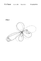
- FIG. 3 illustrates directivity and reachable distances of transmitted/received radio signals in the structure of the adaptive array 2000 shown in FIG. 2;
- FIG. 4 is a schematic block diagram showing the structure of an adaptive array 2000 according to the first embodiment of the present invention.
- FIG. 5 is a flow chart for illustrating operations of a received power measuring circuit 2300 ;
- FIG. 6 is a flow chart for illustrating operations of transmit weight vector control parts 2410 and 2510 ;
- FIG. 7 is a schematic block diagram for illustrating directivity and reachable distances of transmit radio waves in the case of performing the processing shown in FIG. 6;
- FIG. 8 is a flow chart for illustrating operations of a transmit weight vector control part in a second embodiment of the present invention.
- FIG. 9 is a flow chart for illustrating operations of a transmit weight vector control part in a third embodiment of the present invention.
- FIG. 10 is a model diagram conceptually showing basic operations of adaptive array radio base stations
- FIG. 11 is a schematic block diagram showing the structure of a conventional adaptive array radio apparatus
- FIG. 12 is a model diagram imaging transfer of a radio signal between an adaptive array base station and a user.
- FIG. 13 is a diagram showing the concept of transmission/receiving of data between base stations and mobile terminal units.
- FIG. 1 is a schematic block diagram showing the structure of a transmission/receiving system 1000 of a PDMA base station.
- antennas # 1 to # 4 are provided for identifying users PS 1 and PS 2 .
- outputs of the antennas # 1 to # 4 are supplied to an RF circuit 1010 , amplified by a receiving amplifier and frequency-converted by a local oscillation signal in the RF circuit 1010 , thereafter subjected to removal of undesired frequency components through a filter, A-D converted and thereafter supplied to a digital signal processor 1020 as digital signals.
- the digital signal processor 1020 is provided with a channel allocation reference calculator 1030 , a channel allocator 1040 and an adaptive array 2000 .
- the channel allocation reference calculator 1030 previously calculates whether or not signals from the two users PS 1 and PS 2 are separable by the adaptive array 2000 .
- the channel allocator 1040 supplies channel allocation information including user information for selecting frequencies and times to the adaptive array 2000 .
- the adaptive array 2000 weights the signals from the four antennas # 1 to # 4 in real time, thereby separating only a signal from a specific user.
- FIG. 2 is a schematic block diagram showing a first structure of the adaptive array 2000 shown in FIG. 1 .
- the structure of the conventional adaptive array 100 shown in FIG. 11 is simply provided in two systems in correspondence to the two users PS 1 and PS 2 .
- received signals RX i (t) in the four antennas # 1 to # 4 are expressed in the above equations (1) to (4).
- an adaptive array radio base station separates spatially multiplexed received signals through an adaptive array technique, as already described.
- a weight vector Wrx 1 calculated in a receiving circuit of the base station for extracting a signal Srx 1 (t) transmitted from the user PS 1 and a weight vector Wrx 2 for extracting a signal Srx 2 (t) transmitted from the user PS 2 are expressed as follows:
- Wrx 1 [w 11 , w 21 , w 31 , w 41 ] T (16)
- Wrx 2 [w 12 , w 22 , w 32 , w 42 ] T (17)
- w ik represents an i-th weighting factor component of a weight vector for extracting a signal from a k-th terminal.
- weight vectors Wtx 1 and Wtx 2 are prepared by standardizing the weight vectors Wrx 1 and Wrx 2 in receiving as expressed below, for example, in order to form antenna directivity to transmit a transmit signal Stx 1 (t) for the user PS 1 to the user PS 1 and a transmit signal Stx 2 (t) for the user PS 2 to the user PS 2 respectively.
- the weight vector Wtx 1 for transmitting the signal Stx 1 (t) only to the user PS 1 is so controlled that the null point of directivity corresponds to the direction of the user PS 2 . Therefore, the weight vector Wtx 1 forms directivity emitting radio waves not in the direction of the user PS 2 but in the direction of the user PS 1 for the antennas # 1 to # 4 .
- the weight vector Wtx 2 is employed for transmitting the signal Stx 2 (t) only to the user PS 2 . Therefore, it follows that antenna directivity is so formed as to transmit only the signal Stx 1 (t) to the user PS 1 while transmitting only the signal Stx 2 (t) to the user PS 2 .
- the magnitudes of the weight vectors Wtx 1 and Wtx 2 are standardized to 1/M and hence the signals Stx 1 (t) and Stx 2 (t) are transmitted to the users PS 1 and PS 2 with equal transmission power and the total transmission power from the base station is standardized to 1.
- FIG. 3 illustrates radio signals transferred between a base station 1 and the two users PS 1 and PS 2 in a path-divided state in the structure of the adaptive array shown in FIG. 2 .
- the distance between the base station 1 and the second user PS 2 is relatively shorter than that between the base station 1 and the first user PS 1 .
- the base station 1 emits radio waves to the user PS 2 with the same transmission power as that for the user PS 1 , as described above.
- the antenna directivity for the user PS 1 is so controlled that its null point corresponds to the direction for the user PS 2 .
- the base station 1 emits radio waves to the user PS 2 close thereto with excessively large transmission power, and hence the radio signals from the base station 1 to the users PS 1 and PS 2 interfere with each other beyond necessity. This means that it is difficult to widen an area coverable by the base station 1 when sufficiently suppressing interference between the users PS 1 and PS 2 .
- FIG. 4 is a schematic block diagram for illustrating the structure of an adaptive array 2000 in a radio apparatus capable of controlling transmission directivity for suppressing interference of radio signals between two users transmitting/receiving signals to/from the same base station.
- the adaptive array 2000 includes a receiving circuit 2100 for receiving signals from four antennas # 1 to # 4 and separating the signals into those received from users, a transmission circuit 2400 outputting a result of weighting a transmit signal Stx j (t) for each user to be transmittable to each user with directivity, and switching circuits 2010 - 1 to 2010 - 4 provided between the four antennas # 1 to # 4 and the receiving and transmission circuits 2100 and 2400 for switching connection paths between the antennas # 1 to # 4 and the receiving circuit 2100 or the transmission circuit 2400 in transmission and receiving respectively.
- FIG. 4 shows four antennas # 1 to # 4 for simplifying the illustration, the present invention is not restricted to this but more generally applicable to n (n: natural number) antennas.
- the receiving circuit 2100 includes a first received weight vector control part 2110 receiving outputs from the switching circuits 2010 - 1 to 2010 - 4 , multipliers 2120 - 1 to 2120 - 4 outputting results obtained by multiplying the outputs from the corresponding switching circuits 2010 - 1 to 2010 - 4 by weighting factors in response to a weight vector Wrx 1 output from the received weight vector control part 2110 respectively, and an adder 2140 receiving the outputs from the multipliers 2120 - 1 to 2120 - 4 and outputting a result of addition thereof as a received signal Srx 1 (t) from the first user PS 1 .
- the first received weight vector control part 2110 calculates weight vectors W 11 to W 41 through the signals received from the switching circuits 2110 - 1 to 2110 - 4 and a training signal corresponding to the signal from the user PS 1 previously stored in a memory 2130 or the output from the adder 2140 .
- a second received weight vector control part 2210 , multipliers 2220 - 1 to 2220 - 4 , a memory 2230 and an adder 2240 similar in structure to those corresponding to the first user PS 1 are provided in correspondence to a signal Srx 2 (t) received from the second user PS 2 .
- the receiving circuit 2100 is provided with a structure similar to that corresponding to the first user PS 1 .
- the receiving circuit 2100 further includes a received power measuring circuit 2300 for receiving the outputs from the switching circuits 2010 - 1 to 2010 - 4 and measuring received power values of the received radio signals.
- the transmission circuit 2400 includes a first transmit weight vector control part 2410 receiving a transmit signal Stx 1 (t) output to the first user PS 1 and calculating a transmit weight vector Wtx 1 on the basis of the value of a received weight vector for the first user PS 1 from the first received weight vector control part 2110 and received power information for the first user PS 1 from the received power measuring circuit 2300 and multipliers 2420 - 1 to 2420 - 4 receiving the transmit weight vector Wtx 1 output from the first transmit weight vector control part 2410 respectively, multiplying the transmit signal Stx 1 (t) by weighting factors and outputting the results.
- the multipliers 2420 - 1 to 2420 - 4 output signals Stx 1 (t)w 11 , Stx 1 (t)w 21 , Stx 1 (t)w 31 and Stx 1 (t)w 41 respectively.
- the transmission circuit 2400 further includes a second transmit weight vector control part 2520 for generating a transmit signal St 2 (t) for the second user PS 2 and multipliers 2520 - 1 to 2520 - 4 , similarly to those for the first user PS 1 .
- the second transmit weight vector control part 2510 is supplied with received power information RSP 2 for the second user PS 2 from the received power measuring circuit 2300 and information of a received weight vector from the second received weight vector control part 2210 , to output a transmit weight vector Wtx 2 on the basis thereof.
- the received signals in the antennas expressed in the equations (1) to (4) are expressed in vector forms as follows:
- X ( t ) [ RX 1 ( t ), RX 2 ( t ), . . . , RX n ( t )] T (6)
- N ( t ) [ n 1 ( t ), n 2 ( t ), . . . , n n ( t )] T (8)
- the received signal is multiplied by the known user signal, e.g., the signal Srx 1 (t) from the first user PS 1 , to calculate an ensemble mean (time average) as follows:
- E[ . . . ] represents the time average. If the averaging time is sufficiently long, the mean values are as follows:
- the value of the equation (22) is zero since the signals Srx 1 (t) and Srx 2 (t) have no correlation.
- the value of the equation (23) is zero since the signal Srx 1 (t) and a noise signal N(t) have no correlation.
- the received signal factor vector H 1 of the signal transmitted from the first user PS 1 can be measured through the aforementioned procedure.
- a received signal factor vector H 2 of the signal transmitted from the second user PS 2 can be measured by calculating an ensemble mean of the input signal vector X(t) and the signal Srx 2 (t) in a similar manner to the above.
- FIG. 5 is a flow chart showing a procedure of deriving received power P i from each user on the basis of the aforementioned procedure of deriving the received signal factor vector.
- the received power measuring circuit 2300 When measurement of the received power P i is started (step S 100 ), the received power measuring circuit 2300 first confirms the number M of spatial multiplex users (step S 102 ).
- the received power measuring circuit 2300 initializes the value of a parameter i for identifying each spatial multiplex connection user to 1 (step S 104 ).
- step S 106 the value of a parameter t expressing a receiving time is initialized to 1 (step S 106 ).
- a value h ki of a received signal factor vector for an i-th user for a k-th antenna is initialized to zero (step S 107 ), and the value of a parameter k for identifying the antenna is initialized to 1 (step S 108 ).
- the received power measuring circuit 2300 updates the value h ki of the received signal factor vector by adding the value of the product of a received signal RX k (t) received by the k-th antenna at the time t and the i-th user signal Srx i (t) to the value h ki in a stage preceding the time t (step S 110 ).
- step S 112 a determination is made as to whether or not the value of the parameter k is in excess of the number N of the antenna elements (step S 112 ), and if the processing is not completed in correspondence to the number of the antenna elements, the value of the parameter k is incremented by 1 (step S 114 ) for repeating the processing at the step S 110 .
- step S 116 a determination is made as to whether or not the value of the parameter t expressing the time is in excess of a mean time T (step S 116 ). If the value of the parameter t is less than the mean time T, the value of the parameter t is incremented by 1 and the processing returns to the step S 108 .
- the mean time expressing the length of a signal series decided in the communication system, for example, corresponds to 120 symbols in a PHS system, for example.
- step S 16 If the value of the parameter t is in excess of the mean time T (step S 16 ), the value of the parameter k is initialized to 1 again and the value of the received signal power P i for the i-th user is initialized to zero (step S 120 ).
- the value h ki of the received signal factor vector operated between the steps S 108 and S 116 is replaced with a value averaged by dividing the accumulated value h ki by the mean time T, and the value of the received signal power P i is updated to a value obtained by adding the square of the value h ki of the received signal vector to the received signal power P i (step S 122 ).
- step S 124 a determination is made as to whether or not the value of the parameter k is in excess of the number N of the antenna elements (step S 124 ), and if the value of the parameter k is less than the number N of the antenna elements, the value of the parameter k is incremented by 1 (step S 126 ) and the processing returns to the step S 122 .
- step S 124 If the value of the parameter k is determined as exceeding the number N of the antenna elements (step S 124 ), a value obtained by dividing the value of the received signal power P i by the number N of the antenna elements is newly stored in a memory as the received power P i (step S 128 ).
- step S 130 a determination is made as to whether or not the value of the parameter i is in excess of the number M of the spatial multiplex users, and if the value of the parameter i is less than the number M of the users (step S 130 ), the value of the parameter i is incremented by 1 (step S 132 ) and the processing returns to the step S 106 .
- step S 130 If the value of the parameter i is in excess of the number M of the users (step S 130 ), the processing is terminated (step S 134 ).
- the received power P i for the i-th user can be measured on the basis of the value H i of the received signal factor vector for each user through the aforementioned processing.
- the received signal power P i for each user obtained in the aforementioned manner is expressed as follows:
- Wtx 1 ( P 1 Wrx 1 )/(
- Wtx 2 ( P 2 Wrx 1 )/(
- Each of the weight vectors Wtx 1 and Wtx 2 derived through the above equations (27) and (28) has directivity of emitting radio waves only to the direction of the corresponding user.
- the received power P 2 of the user PS 2 is greater than the received power P 1 of the user PS 1 .
- Transmission power is in proportionate to the value of the weight vector and hence the transmission power to the user PS 1 is greater than that to the user PS 2 .
- the total transmission power from the base station 1 is standardized to 1 similarly to the prior art, and hence the transmission power to the terminal (user PS 1 ) far from the base station 1 is increased while that to the terminal (user PS 2 ) close to the base station 1 is suppressed.
- the present invention is not restricted to this but more generally applicable to n antennas and M spatial multiplex connection terminals.
- received power P i for an i-th terminal is expressed as follows:
- the transmit weight vector Wtx i is expressed as follows:
- Wtx i (( P 1 + . . . +P i ⁇ 1 +P i+1 + . . . +P M ) Wrx i )/(
- FIG. 6 is a flow chart showing the flow of processing for deriving each transmit weight vector in the aforementioned procedure.
- the transmit weight vector control part 2410 receives the results of measurement of the number M of the spatial multiplex users and the received power P i thereof from the received power measuring circuit 2300 (step S 202 ).
- the transmit weight vector control part 2410 calculates the transmit weight vector in accordance with the equation (30) and stores the same in a memory (step S 206 ).
- step S 208 a determination is made as to whether or not the value of the parameter i is in excess of the number M of the spatial multiplex users. If the value of the parameter i is less than the number M of the spatial multiplex users (step S 208 ), the value of the parameter i is incremented by 1 (step S 210 ) and the processing returns to the step S 206 .
- step S 208 If the value of the parameter i is in excess of the number M of the spatial multiplex users (step S 208 ), calculation of the transmit weight vector is terminated (step S 212 ).
- a transmit radio signal having directivity to a specific user is generated through the transmit weight vector calculated in the aforementioned manner.
- FIG. 7 illustrates directivity and reachable ranges of radio signals transmitted from the base station 1 to the users PS 1 and PS 2 on the basis of the transmit weight vectors derived in the aforementioned manner in contrast with FIG. 3 .
- the transmit weight vectors are controlled in response to the distances between the receiving terminals and the base station 1 , i.e., in response to the values of the received power, and hence transmission power is suppressed to reduce undesired interference to another cell if the terminal is close to the base station 1 while transmission power to a separate terminal is increased to increase the maximum reachable distance in an established manner.
- the received power measuring circuit 2300 may also have the following structure:
- a base station CS When newly establishing a central channel with a user in a PHS system, for example, a base station CS first performs a carrier sense operation (operation of measuring D/U (signal power-to-interference power ratio) of all communication channels) and specifies a channel having the ratio D/U exceeding a certain constant value or the best ratio D/U as a communication channel for a terminal PS. Then, the terminal PS measures the ratio D/U of the channel specified by the base station CS and starts communication through the specified channel if the ratio D/U exceeds a prescribed value.
- a carrier sense operation operation of measuring D/U (signal power-to-interference power ratio) of all communication channels
- D/U signal power-to-interference power ratio
- Received power is measured also when such a carrier sense operation is performed, and hence the received power measuring circuit 2300 shown in FIG. 4 can also be employed in this case.
- a received signal factor H i of each user PS i included in a received signal is first measured. Then, each signal power P i is obtained from the measured received signal factor vector H i in accordance with the equation (29) for the first embodiment.
- Wtx i (( P 1 1 ⁇ 2 + . . . +P i ⁇ 1 1 ⁇ 2 +P i+1 1 ⁇ 2 + . . . + P M 1 ⁇ 2 ) Wrx i )/(
- the weight vector Wtx i forms directivity emitting radio waves not to the direction of an undesirable user PS i but to the direction of a desirable user PS i .
- FIG. 8 is a flow chart showing the flow of processing for obtaining the transmit weight vector Wtx i in accordance with such a procedure.
- the flow chart shown in FIG. 8 is basically similar to that shown in FIG. 6 except that the calculation formula (31) for the transmit weight vector Wtx i at a step S 306 substitutes for the calculation formula (30) for the transmit weight vector Wtx i at the step S 206 in the flow chart shown in FIG. 6, and hence redundant description is not repeated.
- the transmit weight vector Wtx i is controlled in response to the distance between a receiving terminal and a base station 1 , i.e., in response to the value of the received power P i .
- transmission power is suppressed to reduce undesired interference to another cell if the terminal is close to the base station 1 while transmission power to a terminal far from the base station 1 is increased to increase the maximum reachable distance in an established manner.
- a received signal factor H i of each user PS 1 included in a received signal is first measured. Then, each signal power P i is obtained from the measured received signal factor vector H i in accordance with the equation (29).
- FIG. 9 is a flow chart for illustrating the processing for deriving the transmit weight vector Wtx i according to the third embodiment in the aforementioned manner.
- calculation of the transmit weight vector Wtx i is started at a step S 400 for supplying results of the number M of spatial multiplex users and received power P i thereof from a received power measuring circuit 2300 to a transmit weight vector control part 2410 .
- the transmit weight vector control part 2410 initializes the value of a parameter i for identifying each user to 1 (step S 404 ).
- the transmit weight vector control part 2410 calculates the transmit weight vector Wtx i in accordance with the equation (32) and stores the same in a memory (step S 408 ).
- the transmit weight vector control part 2410 calculates the transmit weight vector Wtx i in accordance with the equation (33) and stores the same in the memory (step S 410 ).
- step S 412 a determination is made as to whether or not the value of the parameter i is in excess of the number M of users (step S 412 ), and if the value of the parameter i is less than the number M of the users, the value of the parameter i is incremented by 1 (step S 414 ) and the processing returns to the step S 406 .
- step S 412 If the value of the parameter i is in excess of the number M of the users (step S 412 ), calculation of the transmit weight vector Wtx i is terminated (step S 416 ).
- the transmit weight vector Wtx i is calculated in response to the distance between a receiving terminal and a base station 1 , i.e., in response to the value of the received power P i , and hence transmission power is suppressed to reduce undesired interference to another cell if the terminal is close to the base station 1 while transmission power to a terminal far from the base station 1 is increased to increase the maximum reachable distance in an established manner.
Abstract
Description
Claims (10)
Applications Claiming Priority (2)
| Application Number | Priority Date | Filing Date | Title |
|---|---|---|---|
| JP27393598A JP3167682B2 (en) | 1998-09-28 | 1998-09-28 | Radio apparatus having transmission directivity and control method therefor |
| JP10-273935 | 1998-09-28 |
Publications (1)
| Publication Number | Publication Date |
|---|---|
| US6636493B1 true US6636493B1 (en) | 2003-10-21 |
Family
ID=17534627
Family Applications (1)
| Application Number | Title | Priority Date | Filing Date |
|---|---|---|---|
| US09/405,139 Expired - Lifetime US6636493B1 (en) | 1998-09-28 | 1999-09-24 | Path division multiple access radio apparatus having directivity control based on received radio strength |
Country Status (2)
| Country | Link |
|---|---|
| US (1) | US6636493B1 (en) |
| JP (1) | JP3167682B2 (en) |
Cited By (17)
| Publication number | Priority date | Publication date | Assignee | Title |
|---|---|---|---|---|
| US20030040281A1 (en) * | 2000-12-27 | 2003-02-27 | Seigo Nakao | Radio apparatus,swap detecting method and swap detecting program |
| US20040053587A1 (en) * | 2000-09-04 | 2004-03-18 | Makoto Nagai | Radio receiving system and method |
| US20040053581A1 (en) * | 2000-12-25 | 2004-03-18 | Masashi Iwami | Radio device with transmission directivity, and control method and control program for the radio device |
| US20040204111A1 (en) * | 2002-12-26 | 2004-10-14 | Juha Ylitalo | Method of allocating radio resources in telecommunication system, and telecommunication system |
| US20050181736A1 (en) * | 2002-03-22 | 2005-08-18 | Aijun Cao | Self & minus; adaptive weighted space time transmitting diversity method and system thereof |
| US20050255891A1 (en) * | 2002-05-15 | 2005-11-17 | Kenichi Takai | Adaptive antenna transmission apparatus, and base station apparatus using the same |
| US7110733B1 (en) * | 1999-10-21 | 2006-09-19 | Matsushita Electric Industrial Co., Ltd. | Array antenna radio communication apparatus and weight coefficient generating method |
| US20060211379A1 (en) * | 2003-03-10 | 2006-09-21 | Ramesh Mantha | System and method for selecting and reselecting antenna direction at a transceiver |
| EP1716646A1 (en) * | 2004-02-12 | 2006-11-02 | Lee, Yong-Hwan | Wireless communication method and apparatus using multiple antennas and multiple random beams |
| US20090258609A1 (en) * | 2002-09-13 | 2009-10-15 | Panasonic Corporation | Radio transmission apparatus and radio transmission method |
| US20090279512A1 (en) * | 2006-04-06 | 2009-11-12 | Kenzaburo Fujishima | Wireless communication system, radio base station apparatus and radio terminal apparatus |
| EP1487140A4 (en) * | 2002-03-20 | 2011-03-23 | Sanyo Electric Co | Radio terminal device, transmission directivity control method, and transmission directivity control program |
| US20110211654A1 (en) * | 2000-08-24 | 2011-09-01 | Sony Deutschland Gmbh | Communication device for receiving and transmitting ofdm signals in a wireless communication system |
| US20140206367A1 (en) * | 2000-06-13 | 2014-07-24 | Comcast Cable Communications, Llc | Method and apparatus for optimization of wireless multipoint electromagnetic communication networks |
| US20140204984A1 (en) * | 2000-06-13 | 2014-07-24 | Comcast Cable Communications, Llc | Apparatus for calculating weights associated with a received signal and applying the weights to transmit data |
| US20160262134A1 (en) * | 2000-09-01 | 2016-09-08 | Intel Corporation | Wireless communications system that supports multiple modes of operation |
| US11296777B2 (en) * | 2015-01-30 | 2022-04-05 | Cassia Networks Inc. | Methods, devices and systems for increasing wireless communication range |
Families Citing this family (13)
| Publication number | Priority date | Publication date | Assignee | Title |
|---|---|---|---|---|
| JP2001111464A (en) | 1999-10-08 | 2001-04-20 | Matsushita Electric Ind Co Ltd | Base station device and method for radio transmission |
| DE10025287B4 (en) * | 2000-05-22 | 2006-06-08 | Siemens Ag | A method and communication system for estimating a downlink interference covariance matrix in cellular mobile radio networks using adaptive antennas |
| JP4056386B2 (en) * | 2000-08-31 | 2008-03-05 | 三洋電機株式会社 | Radio base station, directivity control method in radio base station, and program |
| JP2002199437A (en) * | 2000-12-25 | 2002-07-12 | Kyocera Corp | Base station unit |
| US6788268B2 (en) | 2001-06-12 | 2004-09-07 | Ipr Licensing, Inc. | Method and apparatus for frequency selective beam forming |
| US6448938B1 (en) * | 2001-06-12 | 2002-09-10 | Tantivy Communications, Inc. | Method and apparatus for frequency selective beam forming |
| JP3540784B2 (en) | 2001-08-24 | 2004-07-07 | 三洋電機株式会社 | Radio base station, transmission power control method, and transmission power control program |
| JP3973506B2 (en) | 2002-07-19 | 2007-09-12 | 三洋電機株式会社 | Wireless receiving apparatus, wireless receiving method, and wireless receiving program |
| JP2006140927A (en) | 2004-11-15 | 2006-06-01 | Sanyo Electric Co Ltd | Radio apparatus, and method and program for controlling transmission |
| JP4699154B2 (en) * | 2005-09-29 | 2011-06-08 | 京セラ株式会社 | Receiving device and receiving method |
| JP4791158B2 (en) | 2005-11-24 | 2011-10-12 | 株式会社日立製作所 | Radio base station apparatus and spatial multiplexing transmission number control apparatus |
| JP2008079115A (en) * | 2006-09-22 | 2008-04-03 | Sanyo Electric Co Ltd | Base station, terminal device, and communication method |
| JP5923192B2 (en) * | 2015-03-09 | 2016-05-24 | 日本電信電話株式会社 | Terminal apparatus, base station apparatus, radio communication method, and radio communication system |
Citations (6)
| Publication number | Priority date | Publication date | Assignee | Title |
|---|---|---|---|---|
| JPH05327612A (en) | 1992-05-21 | 1993-12-10 | Sharp Corp | Cordless telephone set |
| US5274844A (en) * | 1992-05-11 | 1993-12-28 | Motorola, Inc. | Beam pattern equalization method for an adaptive array |
| JPH09139704A (en) | 1995-11-13 | 1997-05-27 | Nec Corp | Antenna gain controller for mobile communication system |
| US5999826A (en) * | 1996-05-17 | 1999-12-07 | Motorola, Inc. | Devices for transmitter path weights and methods therefor |
| US6006110A (en) * | 1995-02-22 | 1999-12-21 | Cisco Technology, Inc. | Wireless communication network using time-varying vector channel equalization for adaptive spatial equalization |
| US6466557B1 (en) * | 1997-07-14 | 2002-10-15 | Sanyo Electric Co., Ltd. | Transmission channel allocation method and allocation apparatus |
-
1998
- 1998-09-28 JP JP27393598A patent/JP3167682B2/en not_active Expired - Lifetime
-
1999
- 1999-09-24 US US09/405,139 patent/US6636493B1/en not_active Expired - Lifetime
Patent Citations (7)
| Publication number | Priority date | Publication date | Assignee | Title |
|---|---|---|---|---|
| US5274844A (en) * | 1992-05-11 | 1993-12-28 | Motorola, Inc. | Beam pattern equalization method for an adaptive array |
| JPH05327612A (en) | 1992-05-21 | 1993-12-10 | Sharp Corp | Cordless telephone set |
| US6006110A (en) * | 1995-02-22 | 1999-12-21 | Cisco Technology, Inc. | Wireless communication network using time-varying vector channel equalization for adaptive spatial equalization |
| JPH09139704A (en) | 1995-11-13 | 1997-05-27 | Nec Corp | Antenna gain controller for mobile communication system |
| US5719583A (en) * | 1995-11-13 | 1998-02-17 | Nec Corporation | Mobile communication system which performs antenna gain control |
| US5999826A (en) * | 1996-05-17 | 1999-12-07 | Motorola, Inc. | Devices for transmitter path weights and methods therefor |
| US6466557B1 (en) * | 1997-07-14 | 2002-10-15 | Sanyo Electric Co., Ltd. | Transmission channel allocation method and allocation apparatus |
Non-Patent Citations (8)
| Title |
|---|
| B. Widrow and S. D. Stearns, "Adaptive Signal Processing," Prentice-Hall, Englewood Cliffs (1985). pp. 99-116. |
| B. Widrow et al., "Adaptive Antenna Systems," Proc. IEEE, vol. 55, No. 12, pp. 2143-2159 (Dec. 1967). |
| Copy of Japanese Patent Office Action for corresponding Japanese Patent Application No. 10-273935, including translation of Action. |
| E. Nicolau and D. Zaharia, "Adaptive Arrays," Elsevier, Amsterdam (1989). pp. 122-163. |
| J. E. Hudson, "Adaptive Array Principles," Peter Peregrinus Ltd., London (1981). pp. 59-154. |
| R. T. compton, Jr., "Adaptive Antennas-Concepts and Performance," Pretice-Hall, Englewood Cliffs (1988). pp. 6-11. |
| R.A. Monzingo and T. W. Miller, "Introduction to Adaptive Arrays," John Wiley & Son, New York (1980). pp. 78-105. |
| S.P. Applebaum, "Adaptive Arrays," IEEE Trans. Antennas & Propag., vol. AP-24, No. 5, pp. 585-598 (Sep. 1976). |
Cited By (48)
| Publication number | Priority date | Publication date | Assignee | Title |
|---|---|---|---|---|
| US7110733B1 (en) * | 1999-10-21 | 2006-09-19 | Matsushita Electric Industrial Co., Ltd. | Array antenna radio communication apparatus and weight coefficient generating method |
| US9209871B2 (en) | 2000-06-13 | 2015-12-08 | Comcast Cable Communications, Llc | Network communication using diversity |
| US9106286B2 (en) | 2000-06-13 | 2015-08-11 | Comcast Cable Communications, Llc | Network communication using diversity |
| US9391745B2 (en) | 2000-06-13 | 2016-07-12 | Comcast Cable Communications, Llc | Multi-user transmissions |
| US9820209B1 (en) | 2000-06-13 | 2017-11-14 | Comcast Cable Communications, Llc | Data routing for OFDM transmissions |
| US9722842B2 (en) | 2000-06-13 | 2017-08-01 | Comcast Cable Communications, Llc | Transmission of data using a plurality of radio frequency channels |
| US10349332B2 (en) | 2000-06-13 | 2019-07-09 | Comcast Cable Communications, Llc | Network communication using selected resources |
| US9654323B2 (en) | 2000-06-13 | 2017-05-16 | Comcast Cable Communications, Llc | Data routing for OFDM transmission based on observed node capacities |
| US9401783B1 (en) | 2000-06-13 | 2016-07-26 | Comcast Cable Communications, Llc | Transmission of data to multiple nodes |
| US9356666B1 (en) | 2000-06-13 | 2016-05-31 | Comcast Cable Communications, Llc | Originator and recipient based transmissions in wireless communications |
| USRE45807E1 (en) | 2000-06-13 | 2015-11-17 | Comcast Cable Communications, Llc | Apparatus for transmitting a signal including transmit data to a multiple-input capable node |
| US20140204984A1 (en) * | 2000-06-13 | 2014-07-24 | Comcast Cable Communications, Llc | Apparatus for calculating weights associated with a received signal and applying the weights to transmit data |
| US10257765B2 (en) | 2000-06-13 | 2019-04-09 | Comcast Cable Communications, Llc | Transmission of OFDM symbols |
| US9515788B2 (en) | 2000-06-13 | 2016-12-06 | Comcast Cable Communications, Llc | Originator and recipient based transmissions in wireless communications |
| US9344233B2 (en) | 2000-06-13 | 2016-05-17 | Comcast Cable Communications, Llc | Originator and recipient based transmissions in wireless communications |
| US20140206367A1 (en) * | 2000-06-13 | 2014-07-24 | Comcast Cable Communications, Llc | Method and apparatus for optimization of wireless multipoint electromagnetic communication networks |
| US9197297B2 (en) | 2000-06-13 | 2015-11-24 | Comcast Cable Communications, Llc | Network communication using diversity |
| USRE45775E1 (en) | 2000-06-13 | 2015-10-20 | Comcast Cable Communications, Llc | Method and system for robust, secure, and high-efficiency voice and packet transmission over ad-hoc, mesh, and MIMO communication networks |
| US9954710B2 (en) | 2000-08-24 | 2018-04-24 | Sony Deutschland Gmbh | Communication device for receiving and transmitting OFDM signals in a wireless communication system |
| US20110211654A1 (en) * | 2000-08-24 | 2011-09-01 | Sony Deutschland Gmbh | Communication device for receiving and transmitting ofdm signals in a wireless communication system |
| US9455806B2 (en) | 2000-08-24 | 2016-09-27 | Sony Deutschland Gmbh | Communication device for receiving and transmitting OFDM signals in a wireless communication system |
| US8743675B2 (en) | 2000-08-24 | 2014-06-03 | Sony Deutschland Gmbh | Communication device for receiving and transmitting OFDM signals in a wireless communication system |
| US9596059B2 (en) | 2000-08-24 | 2017-03-14 | Sony Deutschland Gmbh | Communication device for receiving and transmitting OFDM signals in a wireless communication system |
| US20160262134A1 (en) * | 2000-09-01 | 2016-09-08 | Intel Corporation | Wireless communications system that supports multiple modes of operation |
| US9736832B2 (en) * | 2000-09-01 | 2017-08-15 | Intel Corporation | Wireless communications system that supports multiple modes of operation |
| US20040053587A1 (en) * | 2000-09-04 | 2004-03-18 | Makoto Nagai | Radio receiving system and method |
| EP1351412A4 (en) * | 2000-12-25 | 2008-06-18 | Sanyo Electric Co | Radio device with transmission directivity, and control method and control program for the radio device |
| US20040053581A1 (en) * | 2000-12-25 | 2004-03-18 | Masashi Iwami | Radio device with transmission directivity, and control method and control program for the radio device |
| US7233811B2 (en) * | 2000-12-25 | 2007-06-19 | Sanyo Electric Co., Ltd. | Radio device with transmission directivity, and control method and control program for the radio device |
| US20030040281A1 (en) * | 2000-12-27 | 2003-02-27 | Seigo Nakao | Radio apparatus,swap detecting method and swap detecting program |
| US7269202B2 (en) * | 2000-12-27 | 2007-09-11 | Sanyo Electric Co., Ltd. | Radio apparatus, swap detecting method and swap detecting program |
| EP1487140A4 (en) * | 2002-03-20 | 2011-03-23 | Sanyo Electric Co | Radio terminal device, transmission directivity control method, and transmission directivity control program |
| US20050181736A1 (en) * | 2002-03-22 | 2005-08-18 | Aijun Cao | Self & minus; adaptive weighted space time transmitting diversity method and system thereof |
| US7444161B2 (en) * | 2002-03-22 | 2008-10-28 | Huawei Technologies Co., Ltd. | Self & minus; adaptive weighted space time transmitting diversity method and system thereof |
| EP1505744A4 (en) * | 2002-05-15 | 2010-04-21 | Nec Corp | Adaptive antenna transmission apparatus, and base station apparatus using the same |
| US20050255891A1 (en) * | 2002-05-15 | 2005-11-17 | Kenichi Takai | Adaptive antenna transmission apparatus, and base station apparatus using the same |
| US8208488B2 (en) * | 2002-09-13 | 2012-06-26 | Panasonic Corporation | Radio transmission apparatus and radio transmission method |
| US8750325B2 (en) | 2002-09-13 | 2014-06-10 | Panasonic Corporation | Radio transmission apparatus and radio transmission method |
| US9197308B2 (en) | 2002-09-13 | 2015-11-24 | Panasonic Intellectual Property Corporation Of America | Radio transmission apparatus and radio transmission method |
| US20090258609A1 (en) * | 2002-09-13 | 2009-10-15 | Panasonic Corporation | Radio transmission apparatus and radio transmission method |
| US9008115B2 (en) | 2002-09-13 | 2015-04-14 | Panasonic Intellectual Property Corporation Of America | Integrated circuit for controlling radio transmission and reception |
| US20040204111A1 (en) * | 2002-12-26 | 2004-10-14 | Juha Ylitalo | Method of allocating radio resources in telecommunication system, and telecommunication system |
| US20060211379A1 (en) * | 2003-03-10 | 2006-09-21 | Ramesh Mantha | System and method for selecting and reselecting antenna direction at a transceiver |
| EP1716646A4 (en) * | 2004-02-12 | 2011-12-28 | Lee Yong Hwan | Wireless communication method and apparatus using multiple antennas and multiple random beams |
| EP1716646A1 (en) * | 2004-02-12 | 2006-11-02 | Lee, Yong-Hwan | Wireless communication method and apparatus using multiple antennas and multiple random beams |
| US20090279512A1 (en) * | 2006-04-06 | 2009-11-12 | Kenzaburo Fujishima | Wireless communication system, radio base station apparatus and radio terminal apparatus |
| US8340018B2 (en) | 2006-04-06 | 2012-12-25 | Hitachi, Ltd. | Wireless communication system, radio base station apparatus and radio terminal apparatus |
| US11296777B2 (en) * | 2015-01-30 | 2022-04-05 | Cassia Networks Inc. | Methods, devices and systems for increasing wireless communication range |
Also Published As
| Publication number | Publication date |
|---|---|
| JP3167682B2 (en) | 2001-05-21 |
| JP2000106539A (en) | 2000-04-11 |
Similar Documents
| Publication | Publication Date | Title |
|---|---|---|
| US6636493B1 (en) | Path division multiple access radio apparatus having directivity control based on received radio strength | |
| KR101019521B1 (en) | Adjust equipment and method for array antenna transmitting link | |
| KR100382454B1 (en) | Adaptive array antenna transmitting/receiving apparatus | |
| KR100656979B1 (en) | A method for calibrating smart antenna array systems in real time | |
| US7035592B1 (en) | Radio device and method of calibration of antenna directivity | |
| KR100448609B1 (en) | Radio device | |
| KR100363367B1 (en) | Radio communication device and transmitting power control method | |
| JP5047429B2 (en) | Adaptive antenna array method and apparatus for use in a multiple access wireless communication system | |
| US6931244B2 (en) | Radio equipment capable of real time change of antenna directivity and doppler frequency estimating circuit used for the radio equipment | |
| CN100459470C (en) | Self-adaptive antenna receiving apparatus adopting array atenna receiving signal | |
| GB2349045A (en) | Base station transmission beam pattern forming; interference reduction | |
| EP1389837A1 (en) | ARRAY ANTENNA TRANSMITTER/RECEIVER AND ITS CALBRATION METHOD | |
| US6671516B1 (en) | Transmission channel allocation method and radio apparatus using the same | |
| EP0953235A1 (en) | Smart antenna cdma wireless communication system | |
| CN103283159A (en) | Beamforming method, apparatus for polarized antenna array and radio communication device and system thereof | |
| WO2000031823A1 (en) | Adaptive array antenna device | |
| JP2001086049A (en) | Radio base station device and antenna device used for the same | |
| US20050074071A1 (en) | Method and apparatus for diversity combining and co-channel interference suppression | |
| US7079866B2 (en) | Adaptive array antenna and a method of calibrating the same | |
| US7069054B2 (en) | Radio device | |
| US7233811B2 (en) | Radio device with transmission directivity, and control method and control program for the radio device | |
| US7136629B2 (en) | Radio device, radio device calibration system, calibration method, and calibration program | |
| JP3547703B2 (en) | Adaptive array antenna transceiver | |
| EP1146665A1 (en) | Base station device and radio receiving method | |
| KR20120104028A (en) | Method for improving the performance by dynamic grouping/precoding in the mimo radar system |
Legal Events
| Date | Code | Title | Description |
|---|---|---|---|
| AS | Assignment |
Owner name: SANYO ELECTRIC CO., LTD., JAPAN Free format text: ASSIGNMENT OF ASSIGNORS INTEREST;ASSIGNORS:DOI, YOSHIHARU;IINUMA, TOSHINORI;REEL/FRAME:010280/0180 Effective date: 19990914 |
|
| STCF | Information on status: patent grant |
Free format text: PATENTED CASE |
|
| FEPP | Fee payment procedure |
Free format text: PAYOR NUMBER ASSIGNED (ORIGINAL EVENT CODE: ASPN); ENTITY STATUS OF PATENT OWNER: LARGE ENTITY |
|
| FPAY | Fee payment |
Year of fee payment: 4 |
|
| FPAY | Fee payment |
Year of fee payment: 8 |
|
| AS | Assignment |
Owner name: HERA WIRELESS S.A., LUXEMBOURG Free format text: ASSIGNMENT OF ASSIGNORS INTEREST;ASSIGNOR:SANYO ELECTRIC CO., LTD.;REEL/FRAME:033133/0765 Effective date: 20140614 |
|
| FEPP | Fee payment procedure |
Free format text: PAYER NUMBER DE-ASSIGNED (ORIGINAL EVENT CODE: RMPN); ENTITY STATUS OF PATENT OWNER: LARGE ENTITY Free format text: PAYOR NUMBER ASSIGNED (ORIGINAL EVENT CODE: ASPN); ENTITY STATUS OF PATENT OWNER: LARGE ENTITY |
|
| FPAY | Fee payment |
Year of fee payment: 12 |