US6512478B1 - Location position system for relay assisted tracking - Google Patents
Location position system for relay assisted tracking Download PDFInfo
- Publication number
- US6512478B1 US6512478B1 US09/513,982 US51398200A US6512478B1 US 6512478 B1 US6512478 B1 US 6512478B1 US 51398200 A US51398200 A US 51398200A US 6512478 B1 US6512478 B1 US 6512478B1
- Authority
- US
- United States
- Prior art keywords
- relays
- relay
- tag
- tags
- signal
- Prior art date
- Legal status (The legal status is an assumption and is not a legal conclusion. Google has not performed a legal analysis and makes no representation as to the accuracy of the status listed.)
- Expired - Lifetime
Links
Images


Classifications
-
- G—PHYSICS
- G01—MEASURING; TESTING
- G01S—RADIO DIRECTION-FINDING; RADIO NAVIGATION; DETERMINING DISTANCE OR VELOCITY BY USE OF RADIO WAVES; LOCATING OR PRESENCE-DETECTING BY USE OF THE REFLECTION OR RERADIATION OF RADIO WAVES; ANALOGOUS ARRANGEMENTS USING OTHER WAVES
- G01S5/00—Position-fixing by co-ordinating two or more direction or position line determinations; Position-fixing by co-ordinating two or more distance determinations
- G01S5/02—Position-fixing by co-ordinating two or more direction or position line determinations; Position-fixing by co-ordinating two or more distance determinations using radio waves
- G01S5/10—Position of receiver fixed by co-ordinating a plurality of position lines defined by path-difference measurements, e.g. omega or decca systems
-
- G—PHYSICS
- G01—MEASURING; TESTING
- G01S—RADIO DIRECTION-FINDING; RADIO NAVIGATION; DETERMINING DISTANCE OR VELOCITY BY USE OF RADIO WAVES; LOCATING OR PRESENCE-DETECTING BY USE OF THE REFLECTION OR RERADIATION OF RADIO WAVES; ANALOGOUS ARRANGEMENTS USING OTHER WAVES
- G01S5/00—Position-fixing by co-ordinating two or more direction or position line determinations; Position-fixing by co-ordinating two or more distance determinations
- G01S5/02—Position-fixing by co-ordinating two or more direction or position line determinations; Position-fixing by co-ordinating two or more distance determinations using radio waves
- G01S5/0284—Relative positioning
- G01S5/0289—Relative positioning of multiple transceivers, e.g. in ad hoc networks
-
- G—PHYSICS
- G08—SIGNALLING
- G08B—SIGNALLING OR CALLING SYSTEMS; ORDER TELEGRAPHS; ALARM SYSTEMS
- G08B13/00—Burglar, theft or intruder alarms
- G08B13/22—Electrical actuation
- G08B13/24—Electrical actuation by interference with electromagnetic field distribution
- G08B13/2402—Electronic Article Surveillance [EAS], i.e. systems using tags for detecting removal of a tagged item from a secure area, e.g. tags for detecting shoplifting
- G08B13/2451—Specific applications combined with EAS
- G08B13/2462—Asset location systems combined with EAS
-
- G—PHYSICS
- G08—SIGNALLING
- G08B—SIGNALLING OR CALLING SYSTEMS; ORDER TELEGRAPHS; ALARM SYSTEMS
- G08B21/00—Alarms responsive to a single specified undesired or abnormal condition and not otherwise provided for
- G08B21/02—Alarms for ensuring the safety of persons
- G08B21/0202—Child monitoring systems using a transmitter-receiver system carried by the parent and the child
- G08B21/0269—System arrangements wherein the object is to detect the exact location of child or item using a navigation satellite system, e.g. GPS
-
- G—PHYSICS
- G08—SIGNALLING
- G08B—SIGNALLING OR CALLING SYSTEMS; ORDER TELEGRAPHS; ALARM SYSTEMS
- G08B25/00—Alarm systems in which the location of the alarm condition is signalled to a central station, e.g. fire or police telegraphic systems
- G08B25/009—Signalling of the alarm condition to a substation whose identity is signalled to a central station, e.g. relaying alarm signals in order to extend communication range
-
- G—PHYSICS
- G01—MEASURING; TESTING
- G01S—RADIO DIRECTION-FINDING; RADIO NAVIGATION; DETERMINING DISTANCE OR VELOCITY BY USE OF RADIO WAVES; LOCATING OR PRESENCE-DETECTING BY USE OF THE REFLECTION OR RERADIATION OF RADIO WAVES; ANALOGOUS ARRANGEMENTS USING OTHER WAVES
- G01S13/00—Systems using the reflection or reradiation of radio waves, e.g. radar systems; Analogous systems using reflection or reradiation of waves whose nature or wavelength is irrelevant or unspecified
- G01S13/87—Combinations of radar systems, e.g. primary radar and secondary radar
- G01S13/878—Combination of several spaced transmitters or receivers of known location for determining the position of a transponder or a reflector
-
- G—PHYSICS
- G01—MEASURING; TESTING
- G01S—RADIO DIRECTION-FINDING; RADIO NAVIGATION; DETERMINING DISTANCE OR VELOCITY BY USE OF RADIO WAVES; LOCATING OR PRESENCE-DETECTING BY USE OF THE REFLECTION OR RERADIATION OF RADIO WAVES; ANALOGOUS ARRANGEMENTS USING OTHER WAVES
- G01S5/00—Position-fixing by co-ordinating two or more direction or position line determinations; Position-fixing by co-ordinating two or more distance determinations
- G01S5/02—Position-fixing by co-ordinating two or more direction or position line determinations; Position-fixing by co-ordinating two or more distance determinations using radio waves
- G01S5/0205—Details
- G01S5/0215—Interference
-
- G—PHYSICS
- G01—MEASURING; TESTING
- G01S—RADIO DIRECTION-FINDING; RADIO NAVIGATION; DETERMINING DISTANCE OR VELOCITY BY USE OF RADIO WAVES; LOCATING OR PRESENCE-DETECTING BY USE OF THE REFLECTION OR RERADIATION OF RADIO WAVES; ANALOGOUS ARRANGEMENTS USING OTHER WAVES
- G01S5/00—Position-fixing by co-ordinating two or more direction or position line determinations; Position-fixing by co-ordinating two or more distance determinations
- G01S5/02—Position-fixing by co-ordinating two or more direction or position line determinations; Position-fixing by co-ordinating two or more distance determinations using radio waves
- G01S5/0205—Details
- G01S5/0218—Multipath in signal reception
Definitions
- the present invention relates to U.S. Provisional Application No. 60/171,750, filed Dec. 22, 1999, and U.S. Provisional Application No. 60/173,936 filed Dec. 30, 1999, from which priority is claimed.
- This invention relates generally to the field of location-position systems, methods and apparatuses and, in particular embodiments, to relay assisted location-position systems, methods and apparatuses which employ the use of Radio Frequency (RF) tags and data relays.
- RF Radio Frequency
- Location position (LP) systems ascertain positions of particular objects and/or track the locations of objects. Historically, location position systems have been quite diverse. Some location position (LP) systems and processes have typically employed sensor devices, such as motion sensors, heat sensors, or the like, for detecting the presence of an object or personnel to be located or tracked. Other LP systems have employed labels or tag elements, such as, for example, bar codes, RF labels, short-range RF tags, long-range RF tags, and the Global Positioning System (GPS) which provide a signal that has location information or is indicative of location by virtue of its transmission.
- GPS Global Positioning System
- An anti-personnel mine is basically a proximity sensor coupled to an explosive charge.
- An anti-personnel landmine is one that detects the presence of a target, for example an enemy soldier, and in response, initiates an explosive charge within the proximity of the detected enemy.
- Such anti-personnel landmines typically detect whether a target is present or absent from a designated area (i.e. in a local position), but do not track or ascertain actual locations.
- Anti-personnel land mines have several disadvantages as a military position detection system.
- a first disadvantage is that the activation of one anti-personnel landmine provides a warning to any enemy of the possible presence of other landmines.
- a first anti-personnel landmine detonation may provide an element of surprise, but once a first anti-personnel landmine has detonated, any other enemy target within the area will be alerted to the possible presence of other anti-personnel landmines.
- a second drawback of typical anti-personnel landmines is that it does not discriminate between friend and foe.
- Friendly forces wandering into an anti-personnel landmine area may be destroyed by such mines.
- Such anti-personnel landmines are also a threat to friendly forces, during deployment.
- a mine may be accidentally activated or may be activated by the initiation of hostilities before the placement of the mine can be complete.
- Typical anti-personnel landmines also are nondiscriminatory. That is, they may be detonated by nonmilitary personnel in the area, or remain deployed and active well after hostilities cease.
- a LP system comprises machine readable labels or tags have been placed on products or items for inventory control and tracking.
- RF transmitting tags have been affixed to, for example, personnel, vehicles, or other objects to monitor or track the position of such vehicles.
- a variety of commercial type location-position systems are available from various manufacturers.
- One example of commercial (LP) systems is the TirisTM system from Texas Instruments.
- a typical TirisTM system could illustratively comprise a TirisTM transponder and a RFID (radio frequency identification tag) that can be attached or embedded within objects.
- a TirisTM unit sends a radio frequency signal to the tag and the tag broadcasts its stored data back to the TirisTM unit.
- the data broadcast back to the TirisTM unit includes a unique 20-digit code that identifies the RFID tag to the TirisTM unit.
- Such a system provides an identification of an RF tag in close proximity to a TirisTM reader. It, however, provides no location information. Although the TirisTM system can identify an RF tag, it cannot track it.
- PinPoint provides a product called a 3D-iDTM location position system.
- the PinPoint system comprises three basic building blocks: RF tags, cell controllers and software.
- the 3D-iDTM tags can be attached the item desired to be tracked.
- the tag receives 2.4 ghz spreads spectrum signals from the 3D-iDTM system antennas and responds with a 5.8 ghz signal which includes data uniquely identifying the tag.
- Tags can be read at ranges up to 200 feet and hundreds of tags can be read by a single cell controller.
- the 3D-iDTM cell controllers coordinate exchange of data between antennas and the tags.
- the cell controllers communicate with the tags via a 2.4 GHz radio signal.
- the controllers then receive a re-transmitted signal and calculate the time delay between the originally transmitted 2.5 GHz signal and the return 5.8 GHz signal.
- the exact identity and location of the tags can be determined.
- the PinPoint system also comprises viewpoint software which allows a user to display the information gathered by the PinPoint system.
- the PinPoint system can offer both identity and location information in range.
- ATR automatic target recognition
- Signal processing methods which attempt to recognize sound signatures of targets. By processing the sound emitted by various targets, frequency and amplitude relationships can be identified that can be used to distinguish various targets. In addition, by applying multiple sensors and directional principals a target can be located.
- an RF tag and tracking system comprises a plurality of tags (preferably, low-power, radio frequency (RF) identification tags), and a base station and intermediate tracking relays is disclosed.
- tags preferably, low-power, radio frequency (RF) identification tags
- intermediate relays provide single or multi level links between low-powered RF tags and the tracking base station.
- each tag is provided with processing circuitry for determining the location position of the tag.
- position determining computations or functions are instead performed in intermediate relay nodes, which serve as intermediate units between the tags and the positioning base station.
- position determination functions are centralized in a base station, thereby relieving the tags and the intermediate relays of the burden of location position determination.
- tags are automatically activated by a trigger mechanism, for example, upon deployment of the tags.
- a trigger mechanism may also load information corresponding to an initial position into tags, for example, from a GPS signal produced within a deploying mechanism. The tag position can then be tracked by an internal navigation system within the tag.
- FIG. 1 For example, to address a situation in which a number of relays are destroyed or otherwise not functioning. Relays provide multiple paths for conveying information from the tags to a base station.
- Embodiments of the present invention include features that simplify the transmit control. Because the tags transmit asynchronously they do not need a receive function to coordinate transmission between tags. Without a receive function, RF transmissions from the tags cannot be disrupted by an interruption of synchronizing information, because the tags do not accept synchronizing information. In addition, dispensing with the need to synchronize transmissions simplifies control within the tags.
- the tags transmit at pseudo-random periods instead of continuously. Pseudo-random transmit periods may be determined by pseudo-random number generators within each tag.
- the pseudo-random number generators may have a built-in seed number, for example, implanted during manufacture, to generate pseudo-random numbers or may generate pseudo-random numbers using pre-assigned tag identification numbers, serial numbers, or the like.
- LPE low probability of exploitation
- the tags are able to conserve energy by not transmitting in a continuous mode. Because the tags transmit sporadically, power can be conserved by power cycling parts of the circuitry within the tag when they are not being used. Additionally, the sporadic transmission allows more tag transmissions with reduced transmission collision at the relays or base stations. Additional tag transmissions can be accommodated by increasing the mean time between transmissions from the tags. The mean time between transmissions can be increased by changing the software which generates the pseudo random transmit periods.
- Tags can also be tailored for specific applications, for example, tag transmissions can incorporate information in addition to an identifier. For example, in warehousing applications the tag may incorporate a list of items stored within a container. A tag then would not only give the position of the container, but also a list of its contents.
- FIG. 1 is a generalized graphical representation of a location position (LP) system according to an embodiment of the present invention.
- FIG. 1A is a generalized graphical representation of an alternate location position system according to a further embodiment of the present invention.
- FIG. 2A is a generalized graphical representation of a location position (LP) system with distributed Time Delay Of Arrival (TDOA), according to an embodiment of the present invention.
- LP location position
- TDOA distributed Time Delay Of Arrival
- FIG. 2B is a block diagram of an example Radio Frequency (RF) tag as may be used with the embodiment illustrated in FIG. 2 A.
- RF Radio Frequency
- FIG. 2C is a generalized cross-sectional representation of an example tag dispenser as may be used with the embodiment illustrated in FIG. 2 A.
- FIG. 2D is a generalized block diagram of an example relay as may be used with the embodiment illustrated in FIG. 2 A.
- FIG. 2E is a generalized block diagram of an example base station as may be used with the embodiment illustrated in FIG. 2 A.
- FIG. 3A is a generalized graphical representation of a location position (LP) system with centralized Time Delay Of Arrival (TDOA), according to an embodiment of the present invention.
- LP location position
- TDOA Time Delay Of Arrival
- FIG. 3B is a generalized block diagram of an example relay, as may be used with the embodiment illustrated in FIG. 3 A.
- FIG. 4A is a generalized graphical representation of a direct Inertial Navigation System (INS), according to an embodiment of the present invention.
- INS Inertial Navigation System
- FIG. 4B is a generalized schematic illustration of the components of an exemplary Inertial Navigation System (INS).
- INS Inertial Navigation System
- FIG. 4C is a generalized block diagram of an example tag as may be used with the embodiment of the invention illustrated in FIG. 4 A.
- FIG. 4D is a generalized graphical illustration of an example dispenser as may be used with the embodiment of the invention illustrated in FIG. 4 A.
- FIG. 4E is a generalized block diagram of an example relay as may be used with the embodiment of the invention illustrated in FIG. 4 A.
- FIG. 5A is a generalized graphical illustration of a networked Inertial Navigation System (INS) embodiment of the invention.
- INS Inertial Navigation System
- FIG. 5B is a generalized block diagram of a relay as may be used with the embodiment of the invention illustrated in FIG. 5 A.
- FIG. 6 is a generalized block diagram of an alternate embodiment of a tag, as may be used with an embodiment of the invention wherein the tag determines its own position.
- FIG. 7 is a generalized graphical illustration of a multipath problem addressed by embodiments of the present invention.
- FIG. 8A is a generalized block diagram of a digital binary phase shift keying transmitter with digital in phase and quadrature spreading codes, as may be used within an RF tag according to embodiments of the invention.
- FIG. 8B is a generalized block diagram of a digital direct transmitter with a digital spreading code as may be used in RF tags according to further embodiments of the invention.
- FIG. 9 is a generalized schematic diagram of a relay receiver, according to a further embodiment of the invention.
- FIG. 10 is a generalized block diagram of multi-user discriminator as may be used with embodiments of the invention.
- FIG. 11A is a graphic diagram of a composite signal made up of a desired signal and an interfering signal.
- FIG. 11B is a graphic diagram of a composite signal made up of a desired signal and an interfering signal where an interfering signal is present before the arrival of a desired signal.
- FIG. 12A is a generalized schematic diagram of a power system as may be used within RF tags in embodiments of the present invention.
- FIG. 12B is a generalized schematic diagram of a rechargeable power system for an RF tag as may be used with embodiments of the invention.
- FIG. 13 is a generalized graphical illustration of a system embodiment showing the use of relays with varying range capabilities.
- FIG. 14 illustrates the bootstrapping method.
- FIG. 15 illustrates relay position determination using three other relays.
- the present invention relates, generally, to location position systems, methods and apparatuses, for locating and/or tracking objects or entities.
- embodiments of the invention may be employed in a variety of different applications, including various military, industrial and commercial applications.
- location position systems and methods according to embodiments of the present invention may be used in applications relating to locating and/or tracking inventory, including, but not limited to, inventories of goods, supplies, components used in manufacturing, or manufactured products.
- Such systems and methods may be employed to locate or track luggage, for example, in an airport or bus or train station, or to locate or track postal or courier packages, or the like.
- Location position systems and methods may be used in applications relating to locating and/or tracking personnel, including, but not limited to hospital or business staff, patients, security personnel, children, prison inmates, unauthorized boarder crossers or other individuals or groups. Such systems and methods may also be used for tracking destructive animal pests, animals in zoos, game reserves, parks, or the like.
- Location position systems and methods according to embodiments of the present invention have a variety of military applications as well, including, but not limited to, locating or tracking friendly or enemy troops or equipment.
- applications related to locating and tracking enemy troops or equipment such systems and methods may employ location or tracking information to control or direct smart weapons, such as mortars, missiles, bombs or other projectile, or even stationary weapons such as mines, to target the enemy troops or equipment.
- smart weapons such as mortars, missiles, bombs or other projectile, or even stationary weapons such as mines
- mines stationary weapons
- Representative examples of military and commercial applications are described below to assist in the disclosure of various aspects of the invention. However, it will be understood that aspects of the invention are not limited to the specific representative example embodiments and applications described herein, as many additional applications and subsystems may be devised utilizing the teachings of this disclosure.
- Location position systems and methods employ RF tags that are associated with objects or entities to be located and/or tracked, for example, by being affixed to each object or entity to be located and/or tracked.
- tags can be programmed with information as or before they are attached to objects.
- each tag is preferably provided with a transmitter for transmitting a location identification signal.
- a relay device is located within the transmission range of each tag, for receiving tag transmissions and relaying signals to a base station for further processing.
- the tags are designed to be relatively small and inexpensive, for example, so as to be inconspicuous and disposable.
- the electronics associated with such tags are configured to be relatively simple and require minimal power.
- the tags may be associated with the objects or entities to be located in a variety of manners, including manual or automated placement of a respective tag on each object or entity to be located or tracked.
- each tag may be affixed to a respective object or its container, imbedded in the object, placed next to the object, or otherwise associated with the location of the object.
- the tags may be, for example, affixed to badges, identification cards, or articles of clothing or other items worn or carried by the personnel to be located or tracked.
- tags may be surgically implanted on personnel.
- the tags are deployed in an area in which an object or entity to be tracked or located may or will be passing.
- the tags may be manually or automatically dispensed and associated with objects, such as products, supplies, components or the like, as the objects (or containers containing the objects) are conveyed past a pre-designated location, such as a tagging station along a conveyor path of a production line.
- tags designed to affix (or otherwise associate) themselves with passing objects or entities may be dispersed throughout the general area.
- Such a tag may then be affixed (or otherwise associated) with an object or entity that happen to pass through the general area and which comes within sufficiently close proximity to the tag to allow the tag to affix (or otherwise associate) itself with the passing object or entity.
- tags may simply be manually deployed and associated with each object or entity to be located or tracked.
- tags are dispensed by an automated or manually controlled dispensing apparatus.
- an automatic dispensing apparatus may comprise a device located along the conveyor path of the production line, for dispensing and affixing (or otherwise associating) a tag with each product or component passing the dispensing apparatus on the conveyor path.
- a dispensing apparatus may comprise a device for distributing tags randomly, partially randomly, or even at specific locations within the general area.
- a position location system includes a plurality of tags 201 , a tag dispenser device 203 , one or more relays 205 and at least one base station 207 .
- the base station 207 is a device for accepting information from relays.
- a base station need not be a stationary device and may comprise a variety of configurations such as, for instance, laptop computers or PDA's.
- the tags 201 include transmitting devices which transmit signals, for example, upon the tag being dispensed by the dispenser 203 .
- each tag 201 includes a radio frequency (RF) transmitter which transmits signals containing identification information, such as an unique identification code.
- RF radio frequency
- the relays 205 include receivers located within the transmission range of tags in the area 204 . Each given relay 205 need not be positioned within the transmission range of all of the tags in the area 204 . However, it may be preferred that the group of relays 205 , as a whole, are positioned to receive transmissions from all tags within the area 204 so as to provide the maximum number of paths for transmissions from any tag to a base station. Another reason it may be preferred that the group of relays 205 be positioned within the transmission range of all the tags in the area is that in the case where the relays perform positioning functions, such as time delay measurements or triangulation measurements on the relays, a greater number of measurements can yield a greater number of data points and thereby enhance accuracy.
- the tags 201 are shown in FIG. 1 as having been dispensed by the dispenser 203 and are distributed within a general area 204 .
- the dispenser 203 may comprise an active dispensing device which actively places or propels tags throughout the general area 204 .
- the dispensing device dispenses tags by activating an explosive charge, pneumatic impulse or other propelling means, which propels tags throughout the area 204 .
- the explosive charge (or other propelling means) may be activated, for example, by a proximity sensor designed to detect an enemy soldier, vehicle or the like within a certain proximity of the sensor.
- the proximity sensor may be located within the tag dispenser 203 or, alternatively, at other locations remote from the dispenser, such as at an entry path leading to the general area 204 .
- Such a proximity sensor may include, but is not limited to, a vibration sensor, contact sensor, heat sensor, metal detector, combinations thereof or other suitable sensing or detecting means.
- the explosive charge (or other propelling means) may be activated by a signal transmitted from a remote location, a timing signal provided at a preset time, or the like.
- the dispenser device 203 may comprise a passive dispenser designed to dispense tags passively, for example, by adhering the tag to an enemy soldier or vehicle as the enemy soldier or vehicle brushes against or passes adjacent the dispenser.
- tags 201 may include (or be dispensed with) an adhesive material, attaching hooks, magnetized material or other suitable means for attaching the tags to passing soldiers or vehicles.
- tags 201 distributed within the area 204 by a propellant attach to soldiers or vehicles which are present in the area 204 at the time of disbursement or, alternatively, adhere to soldiers or vehicles which enter into the area at some time after disbursement.
- tags 201 distributed by a passive dispenser device as described above, attach to soldiers or vehicles which brush against or pass sufficiently close to the dispenser.
- the tags may be configured and/or camouflaged to appear as part of the environmental surroundings of the area 204 .
- the tags 201 may be configured to appear as small thorns, cockleburs or other parts of plants that form part of the natural vegetation of such an area.
- a soldier traveling through vegetation within the area 204 may not notice one or more tags that become attached to the soldiers clothing or vehicle.
- a tag 201 dispensed within an area 204 and attached to an enemy soldier or vehicle transmits a signal, which, in one example, includes an identification code unique to the tag or unique to the tag dispenser 203 that dispensed the tag.
- the signal is then received by one or more relays 205 , which transmit corresponding information to a base station 207 .
- FIG. 1A is a generalized graphical representation of an embodiment of an alternate location position system.
- a base station 211 receives transmissions from relays 215 .
- the relays in turn receive transmissions from RF Tags 213 as well other relays 215 .
- the relays 215 have an embedded networking type protocol they can receive signals from both nearby relays 215 and nearby tags 213 .
- the relays 215 can then transmit data received from both nearby relays 215 and nearby RF tags 213 . In this manner information can be passed “bucket brigade” style from a distant tag such as 213 A, which is so far from the base station 211 , that its transmissions could not be directly received by the base station 211 .
- tags 213 and relays 215 By interspersing tags 213 and relays 215 , as shown in FIG. 1A, the system can be extended indefinitely, limited only by the capacity of the relays to transmit data. Using this scheme, tags 213 can be tracked over a large area as long as there are sufficient relays 215 that can form a link between the tag 213 and the base station 211 .
- the signals transmitted by the tags may include location identification information which may be processed by suitable electronics either in the relays 205 or the base station 207 , for identifying the location (or approximate location) of each tag.
- location identification information may be processed by suitable electronics either in the relays 205 or the base station 207 , for identifying the location (or approximate location) of each tag.
- the decision whether to include the processing for position determining in either the relays or base station may depend on a variety of factors such as whether the base station is a large immobile unit, in which case processing power could easily be included or whether it is a small handheld device with limited processing power.
- such location information may be generated or modified by motion sensing devices, such as inertia detectors or gyroscope devices located on the tag or dispensed with the tags.
- location information may comprise satellite-signal positioning system data, such as data generated by a global positioning system (GPS) located on the tag or on the dispenser 204 that dispensed the tag.
- GPS global positioning system
- tag location may be determined by the relays 205 , for example, by triangulation methods well known in the art.
- the base station may include or control automated weapon guiding systems that employ the tag location information to guide, for example, munitions toward the location of the tag. Because the tags 201 might be passively or surreptitiously attached to targets, targets would not likely be forewarned of the positioning and targeting action of the system.
- the surreptitious targeting provided by the tag is in contrast to the conventional anti-personnel mine, which announces its presence through the production of an explosion.
- the tags could be located and/or tracked, the targets could be attacked at a position somewhat remote from the attachment point of the tag. This would provide the advantage of minimizing the risk that the target would be warned of how it was being targeted.
- the system may be employed to implement policies which require visual (or other confirming) verification that the target is an enemy target before firing munitions. Accordingly, embodiments of the present system may minimize collateral damage to friendly forces or indigenous nonmilitary personnel. Furthermore, unlike conventional landmines, tags which had not been dispensed at the cessation of hostilities would offer no hazard and would not required careful tracking and disarmament after the cessation of hostilities.
- Identification tags might also be used to track the location of friendly forces during a mission.
- the tags could be coded with certain ID codes to identify different types of military personnel, e.g., infantry, mortar, etc.
- the system may employ anti-tampering or other security measures to inhibit an enemy from using the tag communications against the friendly forces.
- tags may be controlled to transmit sporadically, to make it difficult to lock to a signal unauthorized information gathering difficult.
- decoy tags could be deployed. The resultant clutter could make it more difficult for an enemy to track all the signals and decide which transmissions provided useful information and which were decoys.
- the location of the position of a transmitting tag may be determined in a variety of manners.
- FIG. 2A is a graphical representation of a networked Time Delay Of Arrival (TDOA) embodiment of the present invention.
- tags 301 may be dispensed and activated.
- the tag may be activated by the dispenser 315 , for example by an inexpensive vibration detector, when dispensed. Actuating tags as they are dispensed can help conserve power.
- the tags may later be activated upon being attached to the target when the target enters the area.
- Each activated tag transmits a unique Identifier (ID) 303 , for example, a multidigit number.
- ID unique Identifier
- the ID 303 transmitted by the tag 301 is received by several relays, for example, relays 305 , 307 and 309 .
- Each relay 305 , 307 and 309 stores the time that it received the ID 303 transmitted from the tag 301 .
- the relays can ascertain the relative location of the tag with respect to the location of the relays 305 , then 307 and 309 . If the position of relays 305 , 307 and 309 is known in advance or determined when the relays are activated, the location of the tag 301 can be computed. Once the position of the tag 301 was determined, it could be transmitted 311 to the base station 313 .
- the relays 305 , 307 and 309 can each individually calculate the position of the tag 301 by comparing the time of arrival of the tag transmission at each individual relay.
- reception time information may be communicated by each relay to base station 313 and tag location computations may be performed at the base station 313 .
- FIG. 2B is a block diagram of an RF tag 301 as may be used with the embodiment of FIG. 2A.
- a trigger 331 activates the tag.
- the trigger may be activated by a dispenser 315 during dispensing.
- the trigger may be activate by action of the tag being attached to a target.
- the trigger may comprise, for example, a magnetically activated switch which is activated upon coming into close proximity with a magnetically conductive material, such as metal components of a vehicle.
- the trigger may comprise an accelerometer switch which is activated by acceleration, such as acceleration generated during dispensing or by movement of the tag when the tag becomes attached to a moving soldier, vehicle or other moving target.
- Other suitable trigger mechanisms may be used in further embodiments of the invention.
- the trigger mechanism 331 can be completely eliminated and the tag activated by providing it with power.
- the tag 301 also contains a power source, for example, a battery 325 which powers other elements of the tag, computing element such as a microprocessor 329 , and a transmitter 327 .
- the power source may comprise a solar cell array, an inductive power supply, or a movement generator, as described below.
- the microprocessor computes time to transmit from a pseudo-random time generating algorithm within the microprocessor.
- the microprocessor also formats the unique ID number of the tag which is then provided to the transmitter for transmission by the antenna 323 . While more expensive tag embodiments may employ synchronized timing means, such as crystal timing devices, the RF tag in FIG.
- the transmitter 327 transmits the tag ID, preferably at pseudo-random times, for example, as dictated by the microprocessor 329 .
- the allowable time between transmissions of RF tag ID is determined by application dependent parameters. For example, if the RF tag is attached to an infantryman it need not be updated through transmission of the ID number as often as would be necessary if the tag were attached to a faster moving vehicle.
- the tag may also transmit less frequently on dection of inactivity, such as lack of motion.
- FIG. 2C is a generalized schematic representation of a dispenser 315 , as may be used with the embodiment of the invention illustrated in FIG. 2 A.
- the dispenser 339 comprises a propellant 343 , to eject the tags 301 , and trigger activator 341 , which will activate the trigger 331 on the RF tags 301 .
- the trigger activator 341 may be a mechanism such as an electromagnet activating a relay within the RF tag, an RF source providing energy to the RF tag, or a variety of other mechanisms well known in the art.
- Other embodiments are not provided with a trigger activator 341 , but instead deploy the tags 301 which automatically become active upon a predetermined delay after deployment.
- FIG. 2D is a generalized block diagram of a relay 305 as may be used with the embodiment illustrated in FIG. 2 A.
- the relay 305 of FIG. 2D includes a receiver 355 for receiving tag transmissions 351 from RF tags 301 and also for receiving relay transmissions 353 from other relay transmitters.
- Other similar embodiments may include means of communicating between relays such as wired connections or optical means.
- wired, optical or other means than radio to communicate the tag 305 would not use antenna 365 to transmit 367 to other relays.
- the antenna 365 could be used for all radio transmissions and receptions.
- the relay contains an accurate time clock and/or an accurate position to determine the arrival or reception time of a tag transmission.
- the relay contains a GPS or precision time unit 357 .
- a GPS unit can provide both an accurate determination of the position of the relay and a highly accurate clock.
- Other embodiments, however, may employ relays installed at predetermined, known positions and an internal crystal controlled clock.
- a first way to determine relay positions is to include a global positioning system (GPS) unit within every relay.
- GPS global positioning system
- the GPS positioning unit could then provide to each of the relays an accurate location determination as well as a highly accurate clock.
- Determining the location of the relays by including a GPS unit within each relay has several drawbacks.
- a first drawback is that including a GPS unit within each relay unit considerably increases the cost of each relay unit. Additionally, each relay must be placed where it is able to receive GPS information. Requiring each relay to be able to receive a GPS signal is quite limiting because it may preclude the use of this type of relay in many applications such as within valleys, under deep underbrush, inside of certain buildings, and may also require that the weather does not interfere with the reception of the GPS signal at the relay units.
- a second method for determining the position of each relay is that it may be programmed when the relay is placed or it may be programmed in if the precise location where the relay will be placed is known.
- Programming the relays with the location has several drawbacks. First of all it requires that each relay be individually programmed. This can be a significant disadvantage over a case where each relay can determine its own location, i.e., within relays that contain a GPS unit.
- Another disadvantage of programming in a location to a relay is that the relay may be moved. If a relay with a programmed-in location were moved it would tend to corrupt the location data for the tags.
- a third method to determine relay positions is to bootstrap from a few neighboring relays with known position into an array of relays. This method of bootstrapping is illustrating in FIG. 14 .
- FIG. 14 is a graphic illustration of a relay and tag environment in which the bootstrapping method of relay positioning may be utilized.
- certain relay's positions are known. Relays having known positions can then communicate to relays in unknown positions. The relays in unknown positions can then use the transmissions from the relays in known positions to ascertain their position. The relays with the newly ascertained position can then in turn transmit to other relays which can then determine their position from the transmissions from the relays whose positions had been determined from the first set of relays.
- FIG. 14 An example of how the bootstrapping method can be used to propagate relay locations through an array of relays can be illustrated with respect to FIG. 14 .
- a field containing both relays and tags is illustrated.
- the tags are represented by the circular elements 1401 .
- the relays are numbered 1403 through 1437 .
- In the illustration 1403 , 1405 , 1407 and 1409 all contain GPS units. Because relays 1403 - 1409 contain GPS units, their positions and an accurate time can be easily determined.
- Relays 1403 - 1409 can be placed, for instance, in an area in which GPS signals are available. The remainder of the relays then need not have GPS signals available to them.
- the bootstrapping method as illustrated in FIG. 14 is initiated when relays 1403 through 1409 determine their positions and the precise time by analyzing GPS signals using techniques well known in the art. After determining their positions and ascertaining a high accuracy time relays 1403 - 1409 then transmit their position and a time stamps relative to the high accuracy GPS time that they received from their GPS units. Assume that only relays 1415 , 1417 and 1425 , Group 1 can receive transmissions from relays 1403 , 1405 , 1407 and 1409 . Because the Group 1 relays comprising relays 1415 , 1417 and 1425 , can receive transmissions from relays 1403 - 1409 , relays 1415 , 1417 and 1425 all may determine their precise positions and a precise clock reference.
- relays 1415 , 1417 and 1425 can also transmit their locations and time stamps.
- relays 1403 , 1405 , 1407 , 1409 , 1415 , 1417 , and 1425 can transmit their positions and time stamps
- relays 1411 , 1413 , 1419 , 1421 , 1423 , 1431 and 1427 of Group 2 can also determine their position and accurate time reference.
- a relay can ascertain its location and an accurate time reference by receiving transmissions from four different relays, and computing the time delay of arrival of the transmissions.
- This situation is similar to the situation in which a ground based GPS system receives transmissions from four different satellites in order to determine its position.
- a relay can determine its position by receiving transmissions from less than four different sources having known positions, and may be able to determine its position by receiving transmission from only one relay in certain limited cases.
- a relay By receiving location and time information from four different relays a relay can always guarantee that it can determine its own position.
- a relay can determine its own position when receiving transmissions from less than four other relays in certain instances where use can be made of topography type information. This is a similar situation to reception of a GPS signal. If for example a relay is only able to receive transmissions from three other relays whose position is known then the relay receiving transmissions from only three relays can ascertain that its position must be one of two positions. This situation is illustrated in FIG. 15 .
- FIG. 15 is an illustration of the determination of a relay position from transmissions from three other relays.
- relays 1501 , 1503 and 1505 precisely know their locations and times.
- Relays 1501 , 1503 and 1505 transmit their position and time to another relay in an unknown position. Assuming that the relay in the unknown position determines that it is 50 meters from relay 1501 , 40 meters from relay 1503 and 50 meters from 1505 . If relays 1501 , 1503 and 1505 are arranged as shown in FIG. 15 then the unknown relay position must either be 1507 or 1509 as illustrated in the diagram. If the relay, whose position is unknown, contains topographical information then it can know if one of the two positions 1507 or 1509 is impossible, and therefore can be eliminated.
- position 1509 is a position that is beneath the ground then the relay in unknown position can safely assume it is in position 1507 and not underneath the ground in position 1509 .
- a relay can determine its position by analyzing the transmissions of less than three relays if it has terrain mapping information contained within the relay.
- the bootstrapping method begins with full relays 1403 through 1409 knowing their positions, having ascertained the positions from internal GPS units.
- relays 1403 through 1409 begin to transmit their coordinates and time information another group of relays, i.e., Group 1 , can determine their positions from the transmissions of relays 1403 - 1409 .
- Group 1 relays begin to transmit their positions more relays are able to determine their positions because in addition to the original group of four relays, i.e., 1403 - 1409 transmissions from the additional three relays, 1415 , 1417 and 1425 , of Group 1 are available.
- relays in Group 2 i.e., 1411 , 1413 , 1419 , 1421 , 1423 , 1431 and 1427 to receive enough information to determine their positions. This procedure continues until all of the deployed relays can determine their positions. This situation is flexible because it allows a virtually infinite number of relays, if they are in close enough proximity with each other, to determine their positions based on just a few GPS enabled relays grouped in an initial neighborhood. By bootstrapping position information from an initial group of relays containing GPS information a large number of relays can have their position determined accurately without having to add more GPS enabled relays.
- transmitters for relays can be similar to transmitters from the RF tags the GPS position determination function can be placed in a few seed tags, containing GPS units, instead of placing the GPS units in relays, and the relays can then bootstrap their locations using the initial positions of the GPS enabled RF seed tags.
- Time may be determined by synchronizing the relays to a common time base, such as choosing one of the relays as a master time.
- a GPS unit 357 is provided for illustrative purposes in FIG. 2 d, because such units are commonly well known to those skilled in the art for providing position and time information.
- Microprocessor 359 and transmitter 361 are powered by a power source, such as battery 363 .
- Alternative power sources including but not limited to solar cell arrays may be employed in place of, or in addition to the battery 363 .
- the transmitter 361 in relay 305 can transmit a base station signal 369 to the base station 313 , and/or a relay signal 367 to other relays 307 or 309 , through the antenna 365 .
- the base station signal may contain position information for one or more RF tags, as described above.
- the relay signal 367 may be used for communicating tag information between relays.
- the microprocessor 359 can be programmed to determine the position of a particular RF tag, as described above. In other embodiments, the microprocessor might receive the transmission from other relays 353 and other tags 351 and format the information for transmission to other relays 367 and the base station 369 without computing the RF tag position.
- the microprocessor 359 might also contain various types of networking protocols, such as a hopping protocol, a flooding protocol, a pacing algorithm, a link state based routing algorithm or a variety of other networking algorithms, in order to route information gathered from the tags to a base station or other relays. Such protocols may be used to extend the range of the RF tags or to provide redundancy and fault tolerance within the system, by providing multiple paths for RF tag data to reach the base station.
- FIG. 2E is a block diagram of a base station 313 as may be used with the embodiment of the invention illustrated in FIG. 2 A.
- the base station 313 includes a receiver 377 for receiving relay transmissions 375 . Transmissions may be received by radio, wired link, optical or other means.
- the base station also includes a power source 383 , which may be a battery or other suitable source of power for powering a processor 381 , including, but not limited to a solar cell array, a generator, a fuel cell array or the like.
- the processor 381 may perform a variety of functions, depending on which functions are performed by the relays. If the position determination has been performed in each individual relay, the processor may receive the information from the individual relays and average the position of the tags as computed by each individual relay. However, if the relays do not perform position determination functions, they may instead be programmed with a networking protocol to ensure that information from all tags including the times of arrivals of transmission from the tags is relayed to the base station. The processor 381 may then use the information of the position of the relays and the time of arrival of the transmission from the individual tags at the relays to compute the position of each of the individual tags. The processor may also implement such algorithms as Kalman filtering to track the position of the tags.
- a Kalman filtering algorithm might be applied within the individual relays 305 , 307 or 309 , if the individual relays are responsible for position determination or at the base station if the base station is responsible for position determination.
- the processor 381 can provide tag position information to a transmitter 379 for transmission as target information 385 , for example, to a fire control system in a military application or a workstation in such applications as asset tracking, personnel tracking, baggage tracking, etc.
- the transmission 385 may be by radio or other means such as fiber optic or wire link.
- FIG. 3A is a generalized graphical representation of a centralized Time Delay Of Arrival (TDOA) embodiment of the present invention.
- the tags 401 transmit their Id signals 403 to a relay 405 .
- each relay is provided with a way of determining the time a tag transmission arrived, such as precision time elements.
- precision time element is one which allows the determination of the difference in the time of arrival of the tag transmissions at the individual relays.
- the relays 405 transmits the time of arrival, of the ID 403 from the tag 401 , along with the particular ID of the tag 401 and the position of the relay to the base station 409 . From these transmissions the base station can determine the position of the individual tags.
- the implementation of the relays within FIG. 3A may be somewhat simpler and less costly than those illustrated in FIG. 2D, because communication between individual relays is not required in the embodiment of 3 A.
- Such a system might be employed in tracking items in a warehouse for example.
- the relays 405 could be placed in fixed positions within the warehouse.
- the tags could then be placed on warehouse items which could be tracked to their place of storage within the warehouse.
- the tags could also be programmed with inventory information such as the date the item was placed in the warehouse.
- the base station unit could then be coupled into the internet, and so information regarding items in the warehouse could be available to sales personnel in the field if they were equipped with Internet Ready wireless devices such as the Palm VII handheld programmable digital assistant (PDA) from 3-COMTM Corp.
- PDA Palm VII handheld programmable digital assistant
- FIG. 3B is a generalized block diagram of a relay as may be used with the embodiment illustrated in FIG. 3 A.
- the relay in FIG. 3B receives a signal 419 transmitted from a tag using a receiver 421 . Since the relay of FIG. 3B does not communicate with other relays, the receiver 421 need not be capable of receiving transmissions from other relays.
- the relay of FIG. 3B includes a position and time determination mechanism, for example, a GPS 423 .
- the relay may store pre-recorded position information, for example, recorded or set at the time when the relay was placed, and may include a precision time determination mechanism or clock.
- the microprocessor 425 draws power from a power source, such as a battery 427 , solar cell array or other suitable power supply, and formats or otherwise processes location information from the GPS system 423 and information from the tag transmission 419 .
- the processed information is provided to a transmitter 429 .
- the transmitter 429 transmits at times determined by the microprocessor 425 .
- the transmitter 429 transmits the location information and the received tag information 419 through antenna 431 , to the base station, as represented by the signal 433 .
- the relay of FIG. 3B is simplified as compared with the relay of FIG. 2D, in that the relay of 3 B receives only transmissions from tags and transmits information only to the base station.
- the relay of FIG. 3B need not contain networking protocol, and so may be less complex and less expensive than the relay in FIG. 3 C.
- the relay of 3 B can be simpler than the relay of 2 D because the microprocessor associated with the relay of 3 B need not compute or process network protocols and need only receive RF tag transmissions and transmit one signal 433 to the base station.
- the relay of FIG. 2D in contrast, must be configured to receive transmissions from the other relays, as well as signals from the tag transmitters, and must transmit signals 367 to other relays as well as signals to the base station 369 . Which implementation is more desirable will be dependent upon the particular application in which the system is used.
- FIG. 4A is a generalized graphical representation of a direct Inertial Navigation System (INS) embodiment of the present invention.
- INS Inertial Navigation System
- a dispenser 501 dispenses and activates RF tags 503 .
- the RF tags compute their own position using an embedded inertial navigation system.
- the position information is then transmitted from the tag, along with the RF tag's identification code, to relays 507 , 509 and 511 .
- the relays then relay the tag location information to a base station 513 .
- the embedded position location approach of FIG. 4A preferably employs relatively precise sensors and circuits to accurately identify the location of the RF tag.
- an Inertial Navigation System provided on each tag obtains data for six degrees of freedom.
- the INS includes, for example, three gyroscopes oriented in ninety degrees to each other and three accelerometers oriented in ninety degrees to each other.
- the size and power consumption requirements of the INS are minimized, so that the tags can be easily deployed and attached to the target and have a maximum operational time.
- MEMS micromachining technology can allow low cost batch fabrication of small size sensors, in accordance with preferred embodiments of the present application.
- Various micromachining techniques are available for MEMS devices which include surface micromachining, bulk micromachining and LIGA (LIGA is a German acronym for lithography electroplating and molding and is a methodology for high aspect ratio micromachining).
- FIG. 4B illustrates an embodiment of a INS having six degrees of freedom.
- the INS 520 comprises an accelerometer module 522 and a gyroscopic module 524 .
- the accelerometer module 522 comprises three identical accelerometers 526 , 528 and 530 , displaced at 90 degrees from each other in the X, Y and Z directions.
- the internal structure of an example accelerometer 530 in the Z direction is illustrated, and is similar to that of the X and Y-direction accelerometers.
- the accelerometer 530 in the Z direction comprises a mass 532 , a spring 534 and a dampener 536 .
- any component of acceleration of the INS in the Z direction will move the mass 532 , the movement of which can be then measured by well known techniques.
- any X component of acceleration will be measured by the X accelerometer 526 and any Y component of acceleration will be measured by the Y accelerometer 528 .
- the Inertial Navigation System must also compensate for the gravitational force. Therefore the six degree of freedom system illustrated in the present embodiment includes three perpendicularly oriented gyroscopes in addition to the accelerometers.
- the gyroscope 540 in the Z direction is illustrated and is similar to the X and Y-direction gyroscopes.
- the gyroscope 540 includes a spinning mass, such as disk 542 , spinning about the Z-direction axis.
- the illustrated embodiment of the INS includes two orthogonally placed gyroscopes in X direction 54 a, and the Y direction 546 .
- gyroscope 542 is illustrated as the traditional spinning disk various other types of gyroscopes are available such as vibrating and optical gyroscopes.
- Vibrating gyroscopes include vibrating string, tuning fork, vibrating shell, hemispherical resonator, and vibrating cylinder.
- Optical gyroscopes include interferometric fiber optic gyro (IFOG) and ring laser gyro.
- IFOG interferometric fiber optic gyro
- IFOG interferometric fiber optic gyro
- vibrating gyroscopes can be fabricated using MEMS micromachining technology, at relatively low cost.
- the illustrated example Inertial Navigation System provides information regarding relative movement of a tag. Therefore to know the absolute position of the RF tag, an initial position must be provided to the RF tag.
- the initial position information can be provided to the RF tag in a variety of ways, including, but not limited to, pre-recorded initial position information stored, for example, at the time that the tag dispenser is placed.
- the RF tags may contain a GPS locator coordinate. The GPS coordinate might be provided on the tag at the time the tag is activated, for example.
- FIG. 4C is a block diagram of a tag 503 as may be used with an embodiment of the invention illustrated in FIG. 4 A.
- the tag 503 includes a signal receiver 525 , a microprocessor 529 , an INS system 531 , a power source 533 , a transmitter 535 and an antenna 537 .
- a signal representing an initial position 523 is provided to the receiver 525 in the RF tag.
- the RF tag may also optionally contain a trigger 527 , to activate the tag.
- the detection and receipt of an initial position signal 523 may be used to initiate the functioning of the tag.
- the microprocessor 529 is powered by a suitable power source, such as battery 533 , and processes the initial position information provided to the receiver 525 and further information from the INS system 531 .
- the microprocessor is programmed to accept an initial position as provided by signal 523 and, based on inputs from the INS system 531 , locate and/or track the position of the RF tag.
- the microprocessor 529 is also programmed to provide the position information and a tag identification number to the transmitter 535 , for transmission from the antenna 537 to a relay.
- the position information signal 523 can be provided to the receiver 525 in a variety of ways.
- the initial position may simply be recorded or programmed into the RF tag through a suitable electrically programmable memory associated with the microprocessor 529 within the tag.
- a position information signal 523 may be provided to an RF tag by a position detection system, such as a GPS, located on the dispenser 501 , as illustrated in FIG. 4 D.
- FIG. 4D is a generalized graphic illustration of a dispenser 501 as may be used with the INS embodiment illustrated in FIG. 4 A.
- the dispenser 501 contains a reservoir 550 of RF tags 503 .
- the tags 553 are expelled from the container by activation of a suitable propellant 551 , as described above.
- the dispenser 501 Simultaneously with, just after, or prior to, the activation of the propellant 551 , the dispenser 501 provides the position information signal corresponding to the position of the dispenser 501 to the RF tags 553 .
- the position of the dispenser may be obtained from a GPS module 547 disposed within the dispenser.
- the dispenser position may have been pre-recorded in a suitable electronic storage device (not shown) in the dispenser, for example, at the time the dispenser was placed in the field.
- a trigger mechanism 545 disposed in the dispenser 501 activates the RF tags and may be used to cause the RF tags to accept a position signal, such as a GPS signal, prior to being expelled from the dispenser 555 .
- the position signal such as a GPS signal
- the position signal can be provided to the RF tags in a variety of ways well known in the art, including, but not limited to, magnetic coupling, capacitive coupling, and radio frequency coupling. Because the position of the tag in the embodiment of FIGS. 4A-4D is computed within the tag, the relay may be relieved of functions of computing the position of the tags.
- FIG. 4E is a generalized block diagram of a relay 507 as may be used with INS embodiments of the invention, such as illustrated in FIG. 4 A.
- the relay includes a receiver 567 , a power source 569 , a microprocessor 571 , a transmitter 573 and an antenna 575 .
- the relay accepts a position signal 565 from an RF tag through the receiver 567 .
- the position information provided by the signal 565 is then processed by the microprocessor 571 and formatted for transmission by the transmitter 573 and antenna 575 .
- the antenna 575 for receiving and transmitting would likely be the same.
- the microprocessor 571 turns on the transmitter 573 for transmission of tag position information to the base station.
- the relay 507 may not even require a transmission antenna. Transmission may be accomplished by other means such as wired or optical links.
- the relays may also contain networking protocol, for example, as illustrated in FIG. 5 A.
- FIG. 5A is a generalized schematic diagram of an Inertial Navigation System (INS) embodiment utilizing an example of a networked relay system.
- INS Inertial Navigation System
- a dispenser 601 activates and expels tag 603 .
- Information from the tags is then provided to nearby relays 605 and 607 .
- the relays using a networking protocol, attempt to provide the signal to other relays and to the base station 611 .
- relays 605 , 607 , and 609 transmit data to each other and the base station 611 by means of radio communications, other embodiments may use other means to communicate, such as wired or optical connections.
- the transmission power of the individual relays may even be decreased if more relays closer together are deployed. Number of relays can be a trade off with transmission power, and hence a system can be tailored to individual application needs.
- the transmitters of the relays can be identical to the transmitters of the tags.
- a tag 603 is programmed to provide a position information signal to relay 605 and 607 .
- the tag 603 is too distant from relay 609 for its signal to reach the relay 609 .
- Relay 605 is programmed to transmit the tag information to the base station and other relays. Relay 605 however, does not have enough signal strength to reach the base station 611 . Relay 607 likewise does not have enough signal strength to reach the base station 611 . Accordingly, relay 607 is programmed to accept information about the position of tag 603 from both relay 605 and from the tag 603 itself.
- Relay 607 then provides the information about tag 603 to relay 609 , which is programmed to then provide the information regarding the position of tag 603 to the base station 611 .
- the position information of the tag can be communicated from a farther distance to a base station than when non-networked relays are used.
- the trade off for the added robustness and distance that the networking protocol provides is an increasing complexity and computational burden within the relays.
- FIG. 5B is a generalized block diagram of a relay as may be used with the networked INS system embodiment illustrated in FIG. 5 A.
- the relay in FIG. 5B includes a receiver 625 , a power source 627 , a microprocessor 629 , a transmitter 631 and an antenna 633 .
- the receiver 625 receives signals 621 transmitted from RF tags 603 , and also receives signals 623 transmitted from other relays.
- a microprocessor 629 powered by a power source such as a battery 627 , is programmed to accept information from signals 621 and 623 .
- the microprocessor 629 is further programmed to aggregate the information, to eliminate duplicate information from tags and relays, and to format the information for transmission by a transmitter 631 .
- the transmitter 633 then transmits the aggregate information as a signal 637 to a base station and also provides a signal 635 to other relays.
- Transmission 635 and transmission 637 may be the same transmission, thus simpifying the relay 600 transmission protocol. Both transmissions may utilize antenna 633 .
- the antenna 633 may also be used by receiver 625 to receive transmissions 621 and 623 .
- FIG. 6 is a block diagram of an alternate embodiment of a RF tag 700 as may be used with embodiments of the invention in which the tag determines its own position.
- a tag may be used instead of a tag containing an inertial navigational system.
- the RF tag 700 contains a GPS receiver 701 , a trigger 703 , a microprocessor 705 , a power source, such as a battery 709 , a transmitter 707 and an antenna 711 .
- the tag 700 is activated by actuation of the trigger circuit 703 as discussed above.
- the GPS receiver 701 produces absolute location information, which is provided to the microprocessor 705 .
- the microprocessor 705 is programmed to format the information provided to it by the GPS Module 701 along with the identifying number of the RF tag (not shown) and then transmit the formatted information, using transmitter 707 and antenna 711 , in a signal 713 for reception by the relays.
- FIG. 7 is a generalized graphical illustration of a multi-path problem, as may be encountered with respect to RF tags and relays.
- an RF tag 901 emits a signal omni-directionally.
- the signal is detected by a relay 913 .
- the signal travels not only in a direct path 903 between the RF tag 901 and the relay 913 , but also indirect paths such as through paths 905 and 907 , wherein the signal from the RF tag 901 is reflected and diffracted from various structures 909 and 911 in the environment.
- the multi-path problem results in delayed reception of “copies of” the signal emitted by RF tag 901 being received at relay 913 .
- the relay To accurately measure the distance between a RF tag 901 and a relay 913 , and hence determine the position of the RF tag 901 , the relay must look for the first occurrence of the signal from the RF tag 901 and ignore other reception times in which the same tag signal is received, even if the first reception occurrence is not the strongest, as might be the case if the direct path is blocked by a object in the environment.
- preferred embodiments may employ spread spectrum modulation techniques.
- direct sequence spread spectrum systems modulate a spreading code onto each bit of data, which may then be detected at lower power levels and in higher interference environments than narrowband transmissions.
- a spreading signal can then modulate a carrier signal by means of, for example, a binary phase shift keying modulator.
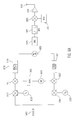
- FIG. 8A is a generalized block diagram of a digital binary phase shift keying (BPSK) transmitter circuit 1000 as may be used with an RF tag, in accordance with an embodiment of the invention.
- a digital signal 1001 is accepted by the circuit 1000 .
- the digital signal 1001 is accepted into spreading units 1003 and 1007 .
- Spreading unit 1003 accepts the digital signal 10001 and spreads it with the spreading code Ci 1005 representative of the in phase spreading code.
- the digital signal 1001 is also accepted by spreading unit 1007 which spreads the digital signal 10001 with a code Cq 1009 which is representative of the quadrature spreading code.
- the spread signal from spreading unit 1003 is coupled into a multiplier 1011 where it is multiplied by a digital representation of a sign wave from a direct digital frequency synthesizer 1013 , and then further provided to digital filter 1019 .
- Digital filter 1019 shapes and filters a digital signal provided by the output of multiplying unit 1011 .
- the output of spreading unit 1007 which spreads the digital signal 1001 with a quadrature code Cq 1009 , is coupled into a digital multiplier 1017 .
- the output of the direct digital frequency synthesizer 1013 is shifted by 90 degrees in a phase shift unit 1015 and then coupled into the digital multiplier 1017 .
- the spread quadrature signal coupled from spreading unit 1007 is multiplied by the direct digital frequency synthesizer signal provided by unit 1013 after being shifted by 90 degrees in phase-shifter 1015 .
- the output of the digital multiplier 1017 is then further coupled into a pulse shaping digital filter 1021 .
- the output of digital filter 1019 is then coupled into a summation unit 1023 and the output value from digital filter 1021 is subtracted from the output of digital filter 1019 in summation unit 1023 .
- the output of the summation unit 1023 is further coupled into a digital analog converter 1023 which is then filtered in a band pass filter 1027 to remove any undesirable frequency components and further coupled into a mixer 1029 .
- the mixer 1029 mixes the output of the band pass filter 1027 with a Voltage Controlled Oscillator (VCO) signal 1031 . It is important to note that the VCO 1031 need not be a crystal controlled frequency source though a crystal controlled frequency source could be used. Eliminating a crystal within the VCO 1031 can significantly lower the cost of the circuit embodiment illustrated in FIG. 8 A.
- the output of the mixer 1029 is then further coupled into an RF amplifier 1033 and then further coupled into an antenna 1035 where it is transmitted, in the present embodiment by radio transmission. Those skilled in the art will note that many variants to the transmission scheme illustrated in FIG. 8A are possible.
- the Digital to Analog Converter (DAC) 1025 could be eliminated with minimal modifications at the cost of some performance degradation. Although the performance would be degraded somewhat by the elimination of the DAC 1925 , the cost of the overall circuit would be lessened.
- FIG. 8B is a generalized block diagram of an example of a digital direct transmitter, with an in-phase digital spreading code only, as may be used RF transmission in accordance with an embodiment of the present invention.
- the direct transmitter illustrated in FIG. 8B accepts a digital bit stream 1041 which is then coupled into a spreading unit 1043 .
- the digital bit stream 1041 is then spread using a spreading code Ci 1045 within spreading unit 1043 .
- the output of spreading unit 1043 is then coupled into a digital low pass filter 1047 .
- the digital low pass filter eliminates any unwanted high frequency components and further provides the filtered signal to the digital to analog converter 1049 .
- the digital to analog converter converts the digital signal from the output of the digital low pass filter 1047 to an analog value.
- the analog output of the digital to analog converter (DAC) is then mixed in mixer 1051 with a signal provided by a voltage control oscillator 1053 .
- the output is then coupled into an RF amplifier 1055 and subsequently provided to an antennae 1057 for broadcast.
- the transmitter embodiment of FIG. 8B while being of somewhat less performance then the embodiment of FIG. 8A, can provide a less expensive solution for transmitting of the RF tag signal.
- the voltage control oscillator 1053 of FIG. 8B need not be a crystal control type oscillator, thereby saving the cost of a crystal in the transmitter of FIG. 8 B.
- the system of FIG. 8B while less efficient then the system of FIG. 8A, is simpler than the system of FIG. 8 A and may be fabricated with less components and so may be employed in systems in which tag size and cost are to be minimized.
- FIG. 9 is a generalized block diagram of circuitry for minimizing interference between tag transmissions.
- the circuitry illustrated in FIG. 9 represents receiver circuitry as may be found in relays in embodiments of the invention.
- an RF tag signal is received by an antenna 1129 and provided to an amplifier 1131 .
- the signal from the RF tag is a spread spectrum signal, which has been modulated using binary phase shift keying techniques
- the output of the amplifier 1131 is provided to a pair of mixers 1141 and 1137 .
- Mixer 1137 mixes the incoming amplified signal from the output of amplifier 1131 with a synthesized signal 1135 generated by an oscillator 1133 .
- the synthesizer output is delayed by 90° and provided to a second mixer 1141 , where it is mixed with the output of the low noise amplifier 1131 .
- the output of mixers 1137 and 1141 are provided into filters 1145 and 1143 , and then converted to digital signals in analogue-to-digital converters (ADCs) 1149 and 1147 , respectively.
- ADCs 1149 and 1147 are then provided to a multi-user discriminator circuit or MUD circuit 1151 and then further provided to rake circuit 1153 .
- Rake circuitry is well known in the art of spread spectrum signal processing.
- Rake receivers are receivers that essentially “rake” as much signal power as possible from the signal environment.
- Rake receivers use energy in signal echoes by integrating information from the main path of a signal along with delayed signal propagation paths to increase the signal strength received and to remove echo-type distortion.
- Rake receivers are commonly used in CDMA cellular phone systems.
- Signals enhanced by the multi-user detector (MUD) 1151 are provided into the rake circuit 1153 .
- the MUD circuit 1151 attempts to improve a received desired signal by subtracting out non-desired received signals from the composite received wave form containing all signals.
- FIG. 10 A generalized block diagram of an example multi-user detection (MUD) unit is depicted in FIG. 10 . While FIG. 10 illustrates one example MUD configuration, those skilled in the art will recognize that a variety of alternative methods have been employed in accomplishing multi-user detection and that alternative techniques may also be suitable.
- the multi-user detection illustrated in FIG. 10 is referred to as a subtractive multi-user detector.
- Subtractive multi-user detection optimally decodes a coded information signal embedded in many other overlapping signals, which make up a received summation or composite signal.
- FIG. 10 illustrates one signal's reception (signal spread by PNI) being enhanced by the MUD.
- the enhancement of a single signal is a simplification for illustrative purposes. In actuality, multiple signals from a plurality of tags would be enhanced by the MUD. Because the MUD unit can subtract out interfering signals in order to discriminate a target signal, the system channel capacity is increased and more tags can be added in a given area.
- a spread spectrum composite signal 1201 is accepted by the MUD system 1202 .
- Composite signal 1201 is then provided to the multi-user detector 1202 .
- the composite signal 1201 is provided to the correlator acquisition unit 1203 .
- the correlator acquisition unit 1203 correlates the incoming code with a particular pseudo-noise code designated as PN 2 1207 .
- the correlator acquisition unit by correlating PN 2 code 1207 with the composite signal 1201 can determine the actual timing between the composite signal and the interfering pseudo-noise signal represented by spreading code PN 2 1207 .
- the correlator acquisition unit provides input to the parameter estimation block 1204 .
- the parameter estimation block estimates what the original signal was in terms of amplitude, data and the phase of the original signal.
- the parameter estimation block produces an estimated signal which is a estimated recreation of the original signal.
- the estimated signal is then coupled into the modulator 1205 and the estimated signal is modulated with this spreading code PN 2 1207 .
- the estimated recreated signal is then coupled from the modulator into the time alignment unit 1222 .
- the time alignment unit 1222 accepts timing information from the correlator acquisition unit which is indicative of the timing of the estimated recreated interfering signal.
- the estimated recreated interfering signal is then delayed as appropriate in the timing alignment unit 1222 and then further coupled to a summation unit 1221 .
- the composite signal also goes through a delay 1220 within the time alignment unit 1218 .
- This delay is to compensate for the time, which the signal takes to travel in the path through the correlator acquisition unit 1203 , parameter estimation unit 1204 , modulator 1205 and time alignment unit 1222 .
- the composite signal is then coupled into the summation unit 1221 .
- correlator acquisition unit 1209 functions with PN code 3 1213 producing data for the parameter estimation unit 1210 which then recreates an estimated interfering signal which is then modulated by the modulator 1211 and coupled into the time alignment unit 1218 .
- the interfering signal is then delayed similarly to the interfering signal in PN 2 .
- the result time aligned interfering signal is then coupled into the summation block 1221 . This continues through any number of similar units accommodating NPN codes.
- the nth corelator acquisition unit 1215 accepts the composite signal 1201 and correlates it with the nth PN code 1219 .
- the parameter estimation block accepts an input from the correlator acquisition unit thereby recreating the nth interfering signal which is then remodulated in the nth modulator 1217 and coupled into the time alignment unit. In similar fashion the recreated nth signal is coupled into the summation block 1221 .
- the summation block 1221 subtracts all the estimated interfering signals from the composite signal thereby producing an output that is much cleaner than the composite signal 1201 .
- the output of the summation block 1221 comprises the composite signal 1201 with all of the interfering signals subtracted out and only the signal containing the PN 1 code remaining.
- the PN 1 code 1225 is then correlated into correlation acquisition unit 1223 . This is done to measure the time delay of arrival of the PN 1 code 1225 .
- the resulting output of the correlator acquisition unit 1223 is a time delay signal 1227 which is proportional to the time that the signal traveled between the RF tag which was transmitting using the PN 1 code, and the relay which received the transmission.
- the decoding correlating units 1203 , 1209 , 1215 and also the composite signal may contain appropriate delay units. For example, if a composite signal contains two signals, a desired signal represented by PN 1 and a undesired signal represented by PN 2 , and the transmission of PN 2 precedes the transmission of PN 1 , the subtraction will not occur until the PN 1 bearing signal is detected. Conversely, if the desired signal represented by PN 1 is transmitted prior to the transmission of the nondesired signal PN 2 , the subtraction of the two signals must be synchronized so that the subtraction process begins only after the signal bearing code PN 2 is detected. The delays may also be used to compensate for processing delays in the circuitry. An example of the subtraction process is illustrated in FIGS. 11A and 11B.
- FIG. 11A is a graphical illustration of a composite signal made up of a desired signal and an interfering signal.
- the composite signal 1239 comprises the addition of the desired signal 1241 and the interfering signal 1243 .
- the desired signal begins transmission at time 1245 and ends transmission at time 1249 .
- the interfering signal begins transmission at point 1247 and ends transmission at point 1251 .
- the composite signal is decoded, beginning at point 1245 , by correlating the composite signal with the PN code of the desired signal.
- the undesired interfering signal 1243 begins transmission.
- the interfering signal 1243 must be decoded by correlation with the PN code of the interfering signal and then subtracted from the composite signal.
- the desired signal terminates transmission, but the interfering signal is not terminated until point 1251 . Therefore, to extract the desired signal 1241 from the composite signal 1239 , the composite signal is correlated with the desired PN code between time 1245 and 1249 , and the undesired interfering signal 1243 is estimated and subtracted from the composite signal between time 1247 and 1249 .
- FIG. 11B illustrates the case where an interfering signal is present before the arrival of a desired signal.
- a composite signal 1253 is comprised of an undesired interfering signal 1257 added to a desired signal 1255 .
- the composite signal is not composed of any component of the desired signal 1255 .
- the transmission of the desired signal begins.
- the interfering signal which has been in the process of being decoded since time 1259 . Its estimate is subtracted from the composite signal 1253 . The subtraction process continues until time 1263 , when the interfering signal terminates. At that time, the remainder of the composite signal and the remainder of the desired signal are identical.
- the timings illustrated in FIGS. 12A and 12B are illustrative simplifications of the timings that must be used in a MUD circuit in order to remove interfering signals from desired signals.
- the previous example has been simplified for purpose of clarity of illustration.
- the interfering signals may need to be removed from a composite signal, in order to enhance the component of the composite signal which is the desired signal.
- the interfering signals as well as the desired signals are signals from the RF tags.
- the transmissions from the RF tags may be generated without the use of a crystal clock, in order to minimize tag costs. Therefore the different RF tags may have different bit timing.
- Receivers within the relays must receive transmission from other relays and tags with potential variations in timing and carrier frequency.
- the relays need to synchronize tag signals having potentially large offsets in frequency and phase in both the transmitted data, for example the chipping rate of the spreading code, and the frequency of the carrier.
- Synchronization of a receiver time base to a frequency and phase timing of transmitted data is often referred to as timing synchronization or timing recovery.
- Synchronization of the receiver local oscillator output for example the output of the synthesizer 1135 of FIG. 9, is often referred to as carrier synchronization or carrier recovery.
- PN pseudo-noise
- the acquisition and tracking functions may be implemented as part of a correlator acquisition unit, such as 1203 illustrated in FIG. 10, to de-spread the interference signals as well as to provide timing information for time delay of arrival (TDOA) measurements.
- TDOA time delay of arrival
- the correlating and decoding units illustrated in FIG. 10, 1203 , 1209 and 1215 may also comprise circuitry that memorizes the time period of the individual previous interfering signal transmissions. If all of the RF tags had clocking signals that were in perfect frequency synchronization, there would be no difference in time period of transmission from the RF tags. Because the clocking of the RF tags may not be crystal controlled (for example, in tag embodiments designed for minimal tag cost), the length of transmission time from each RF tag may vary, even though the same amount of data is being transmitted.
- Preferred embodiments of multi-user detectors will compensate for the differing transmission periods, by timing each transmission period, as it is received, and then decoding the following transmission periods using the timing of the previous transmission period as the expected period.
- the drift in the period of RF transmissions from the RF tags which may be due to the lack of precise crystal time-based frequency synchronization within the tags, can be tracked and memorized. Since frequency drift between successive transmission is likely to be small, the MUD detector can properly function, even though the period of transmission from all RF tags may be continually drifting.
- a future transmission period can be extrapolated. The period of the transmission can then be accurately predicted at the time it is received.
- FIG. 12A is a generalized schematic diagram of an example of a power source for an RF tag, according to an embodiment of the present invention.
- a battery 1301 is connected to a capacitor 1305 , through a switch 1303 .
- the capacitor 1305 then connects to the remainder of the RF tags power circuitry, through contacts 1307 and 1309 .
- the circuitry illustrated in FIG. 12A may also be employed.
- the capacitor 1305 is charged by connection through the switch 1303 to the battery 1301 .
- a charge rate of the capacitor 1305 can be selected so that the current drained from the battery 1301 does not exceed specified peaks.
- Battery 1305 can then be used to power the circuitry of the RF tag during periods of transmission, which are the periods requiring the most consumption of power by the RF tags.
- Other power sources including, but not limited to a solar cell array, or motion generators similar to those found in self-winding watches, might be employed to provide power to the RF tag.
- the tag can conserve power by transmiting only during periods when it detects activity, such as with a motion detector.
- FIG. 12B is a generalized schematic diagram of an example of a rechargeable power source for an RF tag as may be used with embodiments of the invention.
- an antenna coil 1313 is coupled to a capacitor 1317 , through a diode 1315 .
- the capacitor diode and the inductance of the antenna 1313 form a resonant circuit.
- a resonant circuit is responsive to a particular radio frequency.
- the circuit of FIG. 12B is coupled into the RF tags circuitry through contacts 1319 and 1321 . Contacts 1319 and 1321 also may be switched.
- the circuitry of FIG. 12B can be used to accept a high-frequency electromagnetic signal. If the high-frequency electromagnetic signal is of such a frequency, for example, at or near the resonant frequency of the 1313 , 1315 , 1317 series circuit, then capacitor 1317 will be charged.
- Such a circuit may be used in rechargeable versions of the RF tags.
- Such RF tags may be placed on objects to be tracked and then activated as needed. Such RF could lie dormant until they were powered from a suitable frequency electromagnetic signal provided by an external source. The tags then could transmit their numeric identifiers to relays which would then locate the position of each tag, for example, in a manner as described above.
- Bar code tracking systems have the disadvantage that inventory must be visible to the bar code reader.
- Such inventory tracking systems traditionally require a person with a bar code reader to manually place the reader adjacent the bar code to scan the bar code.
- the tag In an inventory system comprising a RF tag with a rechargeable power supply as depicted in FIG. 12B, the tag could be activated merely by causing the tag to be irradiated with the proper frequency electromagnetic radiation.
- the networked relays could also have such a rechargeable power system similar to that shown in FIG. 12 B.
- an electronic inventory of an area could be completed in relatively short order, as compared to bar coding systems that require manual placement of readers adjacent the bar code of each inventoried item.
- Embodiments of the present invention would also have the advantage over bar coding systems in that not only could the products be identified by the numerical identifier transmitted by each tag, the location of the item could be virtually instantaneously determined.
- an inventory system comprising relatively inexpensive, reusable and reprogrammable tags could be fabricated.
- a table look-up system could be implemented in the base station units. In such a system, the RF tags could be reused and reattached to differing inventory items.
- Power consumption is a critical issue in determining just how long a tag or relay, if it is powered internally, will continue to operate. By power cycling parts of the tag and the relay, that is turning off circuitry when not in use, the power consumption can be reduced and operating life extended.
- tags will transmit for a period after receiving a triggering pulse, then after a predetermined period cease transmitting until another trigger pulse is received.
- the amount of time that transmissions will be permitted before the relay or tag goes to sleep can shorten as the power in the relay or tag diminishes.
- shortening the time that the tag or relay will permit transmissions as the power diminishes the tag can increase the time between its asynchronous broadcasts.
- the pseudo-random numbers that are generated by the tags for determining transmission intervals are multiplied by a power saving constant.
- the power saving constant is a function of the amount of power remaining within the tag. In this mode the tag will continue to transmit at pseudo-random intervals, but on the average the pseudo random intervals will increase as the power in the exemplary tag diminishes.
- a similar power saving mode can be implemented within relays.
- the relays can utilize a power saving mode in which the transmission can be based not only on the amount of power remaining in the relay, but additionally how many transmissions it receives. This power saving mode will allow the relay to transmit less as the intervals between tag transmissions increase as the tag power diminishes, thereby allowing the entire system to degrade in a more graceful manner than if the power saving modes had not been implemented. Power saving measures, as just described, can prolong the useful life of a system which operates on internal power.
- FIG. 13 is a generalized block diagram illustrating the use of varying power relays according to an embodiment of the invention.
- RF tags 1335 could communicate with relays 1329 . If, however, the distance between the tags and the base station 1325 were a distance 1331 which is relatively far from the tags, more powerful relays 1327 could be used. Such higher power relays 1327 may be provided with, for example directional antennas or more sensitive receiver circuitry to receive transmissions from the RF tags 1335 . In a further implementation, relays 1327 might receive transmissions from intermediate relays 1329 , which in turn receive transmissions from the RF tags 1335 . By creating successive layers of relay systems, the scope of the RF tag coverage could be increased from a local tracking system to a wide area tracking system.
Abstract
Description
Claims (58)
Priority Applications (6)
| Application Number | Priority Date | Filing Date | Title |
|---|---|---|---|
| US09/513,982 US6512478B1 (en) | 1999-12-22 | 2000-02-26 | Location position system for relay assisted tracking |
| CA002392815A CA2392815C (en) | 1999-12-22 | 2000-12-20 | Location position system for relay assisted tracking |
| JP2001547567A JP2003518261A (en) | 1999-12-22 | 2000-12-20 | Position confirmation system for tracking with relay assist |
| AU27307/01A AU2730701A (en) | 1999-12-22 | 2000-12-20 | Location position system for relay assisted tracking |
| EP00990260A EP1264194A1 (en) | 1999-12-22 | 2000-12-20 | Location position system for relay assisted tracking |
| PCT/US2000/034635 WO2001046711A1 (en) | 1999-12-22 | 2000-12-20 | Location position system for relay assisted tracking |
Applications Claiming Priority (3)
| Application Number | Priority Date | Filing Date | Title |
|---|---|---|---|
| US17175099P | 1999-12-22 | 1999-12-22 | |
| US17393699P | 1999-12-30 | 1999-12-30 | |
| US09/513,982 US6512478B1 (en) | 1999-12-22 | 2000-02-26 | Location position system for relay assisted tracking |
Publications (1)
| Publication Number | Publication Date |
|---|---|
| US6512478B1 true US6512478B1 (en) | 2003-01-28 |
Family
ID=27390019
Family Applications (1)
| Application Number | Title | Priority Date | Filing Date |
|---|---|---|---|
| US09/513,982 Expired - Lifetime US6512478B1 (en) | 1999-12-22 | 2000-02-26 | Location position system for relay assisted tracking |
Country Status (6)
| Country | Link |
|---|---|
| US (1) | US6512478B1 (en) |
| EP (1) | EP1264194A1 (en) |
| JP (1) | JP2003518261A (en) |
| AU (1) | AU2730701A (en) |
| CA (1) | CA2392815C (en) |
| WO (1) | WO2001046711A1 (en) |
Cited By (328)
| Publication number | Priority date | Publication date | Assignee | Title |
|---|---|---|---|---|
| US20010036832A1 (en) * | 2000-04-14 | 2001-11-01 | Onscene, Inc. | Emergency command and control system |
| US20020059420A1 (en) * | 2000-09-09 | 2002-05-16 | Ching-Fang Lin | Networked position multiple tracking process |
| US20020095486A1 (en) * | 2001-01-12 | 2002-07-18 | Paramvir Bahl | Systems and methods for locating mobile computer users in a wireless network |
| US20020118784A1 (en) * | 2000-12-26 | 2002-08-29 | Nortel Networks Limited | Apparatus and method to provide spectrum sharing for two or more RF signals occupying an overlapping RF bandwidth |
| US20020183882A1 (en) * | 2000-10-20 | 2002-12-05 | Michael Dearing | RF point of sale and delivery method and system using communication with remote computer and having features to read a large number of RF tags |
| US20020198986A1 (en) * | 2001-03-09 | 2002-12-26 | Sentinel Wireless, Llc | Location system and methods |
| US20030008722A1 (en) * | 1999-06-14 | 2003-01-09 | Konow Blaine L. | Electronically traceable golf club incorporating a programmable transponder |
| US20030055752A1 (en) * | 2001-09-18 | 2003-03-20 | Thayer Peter A. | System and method for inventory assessment |
| US20030097586A1 (en) * | 2001-11-19 | 2003-05-22 | Mok Steven Siong Cheak | Security system |
| US20030132855A1 (en) * | 2002-01-11 | 2003-07-17 | Swan Richard J. | Data communication and coherence in a distributed item tracking system |
| WO2003062848A2 (en) * | 2002-01-23 | 2003-07-31 | Starchase Llc | Vehicular tracking device |
| US20030163287A1 (en) * | 2000-12-15 | 2003-08-28 | Vock Curtis A. | Movement and event systems and associated methods related applications |
| US20030174086A1 (en) * | 2001-12-21 | 2003-09-18 | International Business Machines Corporation | Determining a time of arrival of a sent signal |
| US20030206115A1 (en) * | 2002-05-01 | 2003-11-06 | John Krumm | Location measurement process for radio-frequency badges |
| US6662078B1 (en) * | 2001-06-25 | 2003-12-09 | William David Hardgrave | System and method for item management via an electronic communication network |
| US20030236619A1 (en) * | 2002-06-25 | 2003-12-25 | The Boeing Company | Low power position locator |
| US6700494B2 (en) * | 2001-07-19 | 2004-03-02 | Dennis O. Dowd | Equine tracking |
| US20040041706A1 (en) * | 2002-09-04 | 2004-03-04 | Stratmoen Scott Alan | Smart and secure container |
| US20040057410A1 (en) * | 2000-05-26 | 2004-03-25 | Kaipiainen Miska Juho Topias | Information transfer between and end user and a radio network, involving the user's wlan-or corresponding identifier and a sub-base station server |
| US20040111340A1 (en) * | 1999-09-03 | 2004-06-10 | Reel Greg T. | Method and system for procuring, storing and distributing remotely accessed data gathered by logging devices |
| US6750769B1 (en) * | 2002-12-12 | 2004-06-15 | Sun Microsystems, Inc. | Method and apparatus for using RFID tags to determine the position of an object |
| US6750757B1 (en) * | 2000-10-23 | 2004-06-15 | Time Domain Corporation | Apparatus and method for managing luggage handling |
| US20040144842A1 (en) * | 2003-01-24 | 2004-07-29 | Cyril Brignone | System and method for distributed storage management |
| US20040174261A1 (en) * | 2003-03-03 | 2004-09-09 | Volpi John P. | Interrogator and interrogation system employing the same |
| US20040189493A1 (en) * | 2003-03-27 | 2004-09-30 | Estus Jay M. | RF electronic license plate and information system for vehicle tracking |
| US20040201454A1 (en) * | 2003-04-09 | 2004-10-14 | Paul Waterhouse | Networked RF tag for tracking freight |
| US20040217859A1 (en) * | 2003-04-30 | 2004-11-04 | Donald Pucci | Radio frequency object locator system |
| US20040232230A1 (en) * | 2000-10-20 | 2004-11-25 | Promega Corporation | Radio frequency identification method and system of distributing products |
| US20050052290A1 (en) * | 2003-09-08 | 2005-03-10 | Axonn L.L.C. | Location monitoring and transmitting device, method, and computer program product using a simplex satellite transmitter |
| US6876325B1 (en) | 2004-04-01 | 2005-04-05 | Itt Manufacturing Enterprises, Inc. | System and method for location-finding using communication signals |
| US20050093702A1 (en) * | 2000-12-22 | 2005-05-05 | Twitchell Robert W.Jr. | Manufacture of LPRF device wake up using wireless tag |
| US20050093703A1 (en) * | 2000-12-22 | 2005-05-05 | Twitchell Robert W.Jr. | Systems and methods having LPRF device wake up using wireless tag |
| US20050099299A1 (en) * | 2003-11-06 | 2005-05-12 | Honeywell International, Inc | Tracking, presence verification and locating features as part of a security system |
| US20050104956A1 (en) * | 2003-09-29 | 2005-05-19 | Fuji Photo Film Co., Ltd. | Imaging device, information storage server, article identification apparatus and imaging system |
| US20050107934A1 (en) * | 2003-11-18 | 2005-05-19 | Caterpillar Inc. | Work site tracking system and method |
| US20050128080A1 (en) * | 2003-02-21 | 2005-06-16 | Hall Larry L. | Cargo lock and monitoring apparatus and process |
| WO2005062067A1 (en) * | 2003-12-03 | 2005-07-07 | Siemens Aktiengesellschaft | System for tracking object locations using self-tracking tags |
| US20050156711A1 (en) * | 2002-10-18 | 2005-07-21 | Aeroscout, Ltd. | Radio-frequency identification (RFID) tag employing unique reception window and method therefor |
| US20050174235A1 (en) * | 2002-05-07 | 2005-08-11 | Davis Brian J. | Tracking system and assosciated method |
| WO2005076772A2 (en) * | 2003-07-21 | 2005-08-25 | Contextual Information, Inc. | Systems and methods for context relevant information management and display |
| US20050200487A1 (en) * | 2004-03-06 | 2005-09-15 | O'donnell Ryan | Methods and devices for monitoring the distance between members of a group |
| US20050215280A1 (en) * | 2000-12-22 | 2005-09-29 | Twitchell Jr Robert W | Lprf device wake up using wireless tag |
| WO2005093453A1 (en) * | 2004-03-25 | 2005-10-06 | Wimcare Interactive Medicine Inc. | Private location detection system |
| US20050258240A1 (en) * | 2004-03-30 | 2005-11-24 | Honeywell International Inc. | Identifying the Location of an Asset |
| EP1610224A1 (en) * | 2003-03-20 | 2005-12-28 | Office Misumi Co., Ltd. | Communication system, communication method, and program thereof |
| US20060012462A1 (en) * | 2004-07-14 | 2006-01-19 | Denso Corporation | Remote control system |
| US20060017545A1 (en) * | 2004-03-26 | 2006-01-26 | Volpi John P | Radio frequency identification interrogation systems and methods of operating the same |
| US20060018274A1 (en) * | 2000-12-22 | 2006-01-26 | Seekernet Incorporated | Communications within population of wireless transceivers based on common designation |
| US20060022825A1 (en) * | 2002-08-09 | 2006-02-02 | Battelle Memorial Institute | System and method for acquisition management of subject position information |
| US20060023678A1 (en) * | 2000-12-22 | 2006-02-02 | Seekernet Incorporated | Forming communication cluster of wireless ad hoc network based on common designation |
| US20060023679A1 (en) * | 2000-12-22 | 2006-02-02 | Seekernet Incorporated | Propagating ad hoc wireless networks based on common designation and routine |
| US20060071757A1 (en) * | 2004-09-24 | 2006-04-06 | Burghard Brion J | Communication methods, systems, apparatus, and devices involving RF tag registration |
| US20060080417A1 (en) * | 2004-10-12 | 2006-04-13 | International Business Machines Corporation | Method, system and program product for automated topology formation in dynamic distributed environments |
| US20060091205A1 (en) * | 2004-11-04 | 2006-05-04 | International Business Machines Corporation | Routing telecommunications to a user in dependence upon location |
| US20060093117A1 (en) * | 2004-11-04 | 2006-05-04 | International Business Machines Corporation | Routing telecommunications to a user in dependence upon device-based routing preferences |
| US20060092874A1 (en) * | 2004-11-04 | 2006-05-04 | International Business Machines Corporation | Establishing user accounts for RFID-based telecommunications routing |
| US20060092015A1 (en) * | 2004-11-04 | 2006-05-04 | International Business Machines Corporation | Notifying users of device events in a networked environment |
| US20060093118A1 (en) * | 2004-11-04 | 2006-05-04 | International Business Machines Corporation | Rerouting ongoing telecommunications to a user |
| US20060109133A1 (en) * | 2000-11-03 | 2006-05-25 | Grose Darren J | Method and apparatus for tracking carcasses |
| US20060113302A1 (en) * | 2004-09-09 | 2006-06-01 | Inteligistics, Inc. | Modular shipping unit and system |
| US20060119476A1 (en) * | 2004-11-23 | 2006-06-08 | Honeywell International, Inc. | MEMS sensor unit for security applications |
| US20060120384A1 (en) * | 2004-12-08 | 2006-06-08 | International Business Machines Corporation | Method and system for information gathering and aggregation in dynamic distributed environments |
| US20060182168A1 (en) * | 2002-12-30 | 2006-08-17 | Dong Wang | Training sequence detection scheme and device of downlink in tdd/cdma system |
| WO2006085280A2 (en) * | 2005-02-10 | 2006-08-17 | Britz Stephan Daniel | Monitoring system |
| US20060192003A1 (en) * | 2000-10-11 | 2006-08-31 | Chung Kevin K | Article tracking system and method |
| US20060192652A1 (en) * | 2005-02-14 | 2006-08-31 | Inteligistics, Inc. | Identification system |
| US20060235792A1 (en) * | 2005-04-14 | 2006-10-19 | International Business Machines Corporation | Tracking a fuel cell |
| US20060240775A1 (en) * | 2004-12-20 | 2006-10-26 | Shoji Kuriki | Data communication apparatus functioning as ID tag and ID-tag reader and writer |
| US20060250300A1 (en) * | 2005-05-06 | 2006-11-09 | Jean-Louis Laroche | RF system for tracking objects |
| US20060250305A1 (en) * | 2004-04-01 | 2006-11-09 | Itt Manufacturing Enterprises, Inc. | Method and system for determining the position of an object |
| US20060276161A1 (en) * | 2005-06-03 | 2006-12-07 | Terahop Networks, Inc. | Remote sensor interface (rsi) stepped wake-up sequence |
| US20060273894A1 (en) * | 2005-06-01 | 2006-12-07 | Rolf Goehler | Emergency rescuer tracking system and method |
| US20060282217A1 (en) * | 2005-06-03 | 2006-12-14 | Terahop Networks, Inc. | Network aided terrestrial triangulation using stars (natts) |
| US20060287008A1 (en) * | 2005-06-17 | 2006-12-21 | Terahop Networks, Inc. | Remote sensor interface (rsi) having power conservative transceiver for transmitting and receiving wakeup signals |
| US20060287822A1 (en) * | 2005-06-16 | 2006-12-21 | Terahop Networks, Inc. | Gps denial device detection and location system |
| US20060289650A1 (en) * | 2005-06-27 | 2006-12-28 | Mobile Aspects, Inc. | Networked monitoring system |
| US20060289204A1 (en) * | 2005-06-08 | 2006-12-28 | Terahop Networks, Inc. | All WEATHER HOUSING ASSEMBLY FOR ELECTRONIC COMPONENTS |
| US20070001854A1 (en) * | 2004-08-26 | 2007-01-04 | Chung Kevin K | Object monitoring, locating, and tracking method employing RFID devices |
| US20070002792A1 (en) * | 2005-07-01 | 2007-01-04 | Terahop Networks, Inc. | Communicating via nondeterministic and deterministic network routing |
| US20070004331A1 (en) * | 2005-06-16 | 2007-01-04 | Terahop Networks, Inc. | tactical gps denial and denial detection system |
| US20070004431A1 (en) * | 2000-12-22 | 2007-01-04 | Seekernet Incorporated | Forming ad hoc rsi networks among transceivers sharing common designation |
| US20070002808A1 (en) * | 2000-12-22 | 2007-01-04 | Seekernet Incorporated | Transmitting sensor-acquired data using step-power filtering |
| US20070014189A1 (en) * | 2005-07-15 | 2007-01-18 | Basilico Albert R | System and method for extending GPS to divers and underwater vehicles |
| WO2005081630A3 (en) * | 2004-03-01 | 2007-02-08 | Chaim Ash | A system and a method for performing wireless measurements by means of a portable coordinate system |
| US20070035383A1 (en) * | 2005-08-09 | 2007-02-15 | Roemerman Steven D | Radio frequency identification interrogation systems and methods of operating the same |
| US20070043807A1 (en) * | 2005-08-18 | 2007-02-22 | Terahop Networks, Inc. | All WEATHER HOUSING ASSEMBLY FOR ELECTRONIC COMPONENTS |
| US20070085682A1 (en) * | 2005-10-17 | 2007-04-19 | Nobuo Murofushi | Moving object management system and moving object apparatus |
| US7207274B1 (en) * | 2004-07-20 | 2007-04-24 | Lockheed Martin Corporation | Sticky polymer lethal agent tracer |
| US20070099629A1 (en) * | 2005-10-31 | 2007-05-03 | Terahop Networks, Inc. | Using gps and ranging to determine relative elevation of an asset |
| US20070109129A1 (en) * | 2005-05-24 | 2007-05-17 | Sundstrom Kurt E | Rfid reader systems detecting pilot tone |
| US7221696B1 (en) * | 2003-03-03 | 2007-05-22 | Itt Manufacturing Enterprises, Inc. | Communication system and method for acquiring pseudonoise codes or carrier signals under conditions of relatively large chip rate uncertainty |
| US20070136154A1 (en) * | 2000-10-16 | 2007-06-14 | Chung Kevin K | Tracking apparatus and method, as for an exhibition |
| US20070139223A1 (en) * | 2005-12-15 | 2007-06-21 | Honeywell International Inc. | Vehicle tracking system |
| US20070152826A1 (en) * | 2003-04-09 | 2007-07-05 | Visible Assets, Inc. | Networked RF tag for tracking baggage |
| US20070152825A1 (en) * | 2003-04-09 | 2007-07-05 | Visible Assets, Inc. | Networked RF tag for tracking baggage |
| US20070164851A1 (en) * | 2006-01-12 | 2007-07-19 | Cooper Scott A | Rfid reader q-parameter aided by rf power measurement |
| US20070178842A1 (en) * | 2006-01-31 | 2007-08-02 | Mutsuya Ii | Method and system for synchronizing geographically distributed RF sensors using a pair of RF triggering devices |
| US20070189215A1 (en) * | 2004-01-07 | 2007-08-16 | Huawei Technologies Co., Ltd. | Method for reducing interface load of home subscriber server |
| US20070202887A1 (en) * | 2006-02-28 | 2007-08-30 | Microsoft Corporation | Determining physical location based upon received signals |
| US7272495B2 (en) | 2004-04-01 | 2007-09-18 | Itt Manufacturing Enterprises, Inc. | System and method for inverse multilateration |
| US20070225911A1 (en) * | 2006-03-23 | 2007-09-27 | Rich Chanick | User positional and venue information integration system and method |
| US20070248358A1 (en) * | 2006-04-19 | 2007-10-25 | Michael Sauer | Electrical-optical cable for wireless systems |
| US20070257831A1 (en) * | 2006-04-28 | 2007-11-08 | Loctronix Corporation | System and method for positioning in configured environments |
| US20070257796A1 (en) * | 2006-05-08 | 2007-11-08 | Easton Martyn N | Wireless picocellular RFID systems and methods |
| US20070262872A1 (en) * | 2005-03-01 | 2007-11-15 | Carrender Curtis L | Multistatic antenna configuration for radio frequency identification (rfid) systems |
| US7298264B1 (en) | 2004-01-20 | 2007-11-20 | Charles A. Eldering | RFID tag filtering and monitoring |
| US20070268138A1 (en) * | 2004-08-26 | 2007-11-22 | Chung Kevin K | Object monitoring, locating, and tracking system and method employing rfid devices |
| US20070285245A1 (en) * | 2006-05-01 | 2007-12-13 | Djuric Petar M | RFID system and method for localizing and tracking a moving object with an RFID tag |
| US20070286599A1 (en) * | 2006-06-12 | 2007-12-13 | Michael Sauer | Centralized optical-fiber-based wireless picocellular systems and methods |
| EP1866665A1 (en) * | 2005-04-07 | 2007-12-19 | National University of Singapore | A system and method for searching physical objects |
| US20070291724A1 (en) * | 2000-12-22 | 2007-12-20 | Terahop Networks, Inc. | Method for supplying container security |
| US20070292136A1 (en) * | 2006-06-16 | 2007-12-20 | Michael Sauer | Transponder for a radio-over-fiber optical fiber cable |
| US20080001744A1 (en) * | 2006-06-16 | 2008-01-03 | Intelleflex Corporation | Rfid device with first clock for data aquisition and/or calibration of second clock |
| US20080018469A1 (en) * | 2003-03-03 | 2008-01-24 | Volpi John P | Interrogator and Interrogation System Employing the Same |
| US20080018432A1 (en) * | 2003-03-03 | 2008-01-24 | Volpi John P | Interrogator and Interrogation System Employing the Same |
| US20080018468A1 (en) * | 2003-03-03 | 2008-01-24 | Volpi John P | Interrogator and Interrogation System Employing the Same |
| US20080018450A1 (en) * | 2003-03-03 | 2008-01-24 | Volpi John P | Interrogator and Interrogation System Employing the Same |
| US20080024276A1 (en) * | 2003-03-03 | 2008-01-31 | Volpi John P | Interrogator and Interrogation System Employing the Same |
| US20080030330A1 (en) * | 2000-12-15 | 2008-02-07 | Vock Curtis A | Product Integrity Tracking Shipping Label, System And Associated Method |
| EP1889089A1 (en) * | 2005-06-03 | 2008-02-20 | Tagent Corporation | Production of radio frequency id tags |
| US20080046492A1 (en) * | 2006-05-19 | 2008-02-21 | Sundstrom Kurt E | Rfid reader systems with digital rate conversion |
| US20080044186A1 (en) * | 2006-08-16 | 2008-02-21 | Jacob George | Radio-over-fiber transponder with a dual-band patch antenna system |
| US20080048833A1 (en) * | 2006-01-12 | 2008-02-28 | Oliver Ronald A | Rfid reader system aided by rf power of measurement |
| US20080055157A1 (en) * | 2006-09-01 | 2008-03-06 | Zafer Sahinoglu | Cooperative passive radar system |
| US20080070502A1 (en) * | 2006-09-15 | 2008-03-20 | Jacob George | Radio-over-fiber (RoF) optical fiber cable system with transponder diversity and RoF wireless picocellular system using same |
| US20080080863A1 (en) * | 2006-09-28 | 2008-04-03 | Michael Sauer | Radio-over-fiber (RoF) wireless picocellular system with combined picocells |
| US20080091681A1 (en) * | 2006-10-12 | 2008-04-17 | Saket Dwivedi | Architecture for unified threat management |
| US7365650B1 (en) | 2005-12-19 | 2008-04-29 | The United States Of America As Represented By The Secretary Of The Navy | Underwater RF propagation path |
| US20080129525A1 (en) * | 2006-11-30 | 2008-06-05 | International Business Machines Corporation | Detecting Hazardous Conditions in Underground Environments |
| US7391321B2 (en) | 2005-01-10 | 2008-06-24 | Terahop Networks, Inc. | Keyhole communication device for tracking and monitoring shipping container and contents thereof |
| US20080150788A1 (en) * | 2006-04-24 | 2008-06-26 | Schaller Engineering, Inc. | Systems and Methods for Tagging, Tracking, Targeting, and Termination of Mobile Targets |
| US7394361B1 (en) | 2005-01-10 | 2008-07-01 | Terahop Networks, Inc. | Keyhole communication device for tracking and monitoring shipping container and contents thereof |
| US20080186143A1 (en) * | 2007-02-06 | 2008-08-07 | Jacob George | Transponder systems and methods for radio-over-fiber (ROF) wireless picocellular systems |
| US7411506B2 (en) | 2003-03-03 | 2008-08-12 | Veroscan, Inc. | Interrogator and interrogation system employing the same |
| US7420458B1 (en) | 2004-01-20 | 2008-09-02 | Charles A. Eldering | Secondary card reader |
| JP2008535722A (en) * | 2005-04-11 | 2008-09-04 | サン キム,ジュング | Emergency rescue system by tracking sea position for life jackets |
| US20080218348A1 (en) * | 2006-04-12 | 2008-09-11 | Visible Assets Inc. | Visibility radio cap and network |
| US20080245299A1 (en) * | 2007-04-04 | 2008-10-09 | Dycom Identity, Llc | Marking system and method |
| US7450006B1 (en) | 2006-04-06 | 2008-11-11 | Doyle Alan T | Distributed perimeter security threat confirmation |
| US20080304443A1 (en) * | 2000-12-22 | 2008-12-11 | Twitchell Jr Robert W | Standards based communictions for a container security system |
| US20090016308A1 (en) * | 2000-12-22 | 2009-01-15 | Terahop Networks, Inc. | Antenna in cargo container monitoring and security system |
| US20090021345A1 (en) * | 2001-12-21 | 2009-01-22 | Mobile Aspects | Dynamic Control Containment Unit |
| US20090033494A1 (en) * | 2007-07-31 | 2009-02-05 | Symbol Technologies, Inc. | Vehicular mobile rf tags |
| US20090036104A1 (en) * | 2007-07-31 | 2009-02-05 | Symbol Technologies, Inc. | Mobile rf tags locatable using cell phone |
| US20090043502A1 (en) * | 2007-08-10 | 2009-02-12 | Cisco Technology, Inc. | System and Method for Navigating Using Multiple Modalities |
| US20090045917A1 (en) * | 2007-08-13 | 2009-02-19 | Volpi John P | Interrogator and Interrogation System Employing the Same |
| US20090045965A1 (en) * | 2003-04-09 | 2009-02-19 | Visible Assets, Inc. | Networked RF tag for tracking baggage |
| US20090058646A1 (en) * | 2003-04-09 | 2009-03-05 | Visible Assets, Inc. | Networked RF tag for tracking baggage |
| US20090079616A1 (en) * | 2007-09-20 | 2009-03-26 | Lockheed Martin Corporation | Covert long range positive friendly identification system |
| US20090104902A1 (en) * | 2000-12-22 | 2009-04-23 | Terahop Networks, Inc. | Class-switching in class-based data communcations network |
| US7526381B2 (en) | 2005-06-03 | 2009-04-28 | Terahop Networks, Inc. | Network aided terrestrial triangulation using stars (NATTS) |
| US20090109033A1 (en) * | 2007-09-26 | 2009-04-30 | Roberto Salvat | Medical System And Tracking Device |
| US20090124302A1 (en) * | 2000-12-22 | 2009-05-14 | Terahop Networks, Inc. | WIRELESS READER TAGS (WRTs) WITH SENSOR COMPONENTS IN ASSET MONITORING AND TRACKING SYSTEMS |
| US20090122737A1 (en) * | 2007-02-21 | 2009-05-14 | Terahop Networks, Inc. | Mesh network control using common designation wake-up |
| US20090129306A1 (en) * | 2007-02-21 | 2009-05-21 | Terahop Networks, Inc. | Wake-up broadcast including network information in common designation ad hoc wireless networking |
| US20090141591A1 (en) * | 2005-07-15 | 2009-06-04 | Basilico Albert R | System and Method for Extending GPS to Divers and Underwater Vehicles |
| FR2924818A1 (en) * | 2007-12-06 | 2009-06-12 | Commissariat Energie Atomique | Remote localization system for e.g. military operation, has master node determining difference between free node and master node, and free node and reference node to deduce relative position of free node |
| US20090160620A1 (en) * | 2003-04-09 | 2009-06-25 | Visible Assets Inc. | Smartbeam Visibility Network |
| US20090160605A1 (en) * | 2005-09-29 | 2009-06-25 | Roemerman Steven D | Interrogation System Employing Prior Knowledge About an Object to Discern an Identity Thereof |
| US7554442B2 (en) | 2005-06-17 | 2009-06-30 | Terahop Networks, Inc. | Event-driven mobile hazmat monitoring |
| US20090174569A1 (en) * | 2003-10-22 | 2009-07-09 | Awarepoint Corporation | Plug-In Network Appliance |
| US7574168B2 (en) | 2005-06-16 | 2009-08-11 | Terahop Networks, Inc. | Selective GPS denial system |
| US20090201178A1 (en) * | 2007-03-13 | 2009-08-13 | Nielsen Steven E | Methods for evaluating operation of marking apparatus |
| US20090204238A1 (en) * | 2007-03-13 | 2009-08-13 | Nielsen Steven E | Electronically controlled marking apparatus and methods |
| US20090212117A1 (en) * | 2003-04-09 | 2009-08-27 | Visible Assets Inc. | Networked Loyalty Cards |
| US20090216587A1 (en) * | 2007-06-20 | 2009-08-27 | Saket Dwivedi | Mapping of physical and logical coordinates of users with that of the network elements |
| US20090212918A1 (en) * | 2003-10-24 | 2009-08-27 | Symbol Technologies | Radio Frequency Identification (RFID) Based Sensor Networks |
| US7583769B2 (en) | 2005-06-16 | 2009-09-01 | Terahop Netowrks, Inc. | Operating GPS receivers in GPS-adverse environment |
| US20090280819A1 (en) * | 2008-05-07 | 2009-11-12 | At&T Mobility Ii Llc | Femto cell signaling gating |
| US20090286544A1 (en) * | 2008-05-13 | 2009-11-19 | At&T Mobility Ii Llc | Administration of an access control list to femto cell coverage |
| US20090298470A1 (en) * | 2008-05-13 | 2009-12-03 | At&T Mobility Ii Llc | Administration of access lists for femtocell service |
| US20090322510A1 (en) * | 2008-05-16 | 2009-12-31 | Terahop Networks, Inc. | Securing, monitoring and tracking shipping containers |
| US20100013635A1 (en) * | 2008-05-16 | 2010-01-21 | Terahop Networks, Inc. | Locking system for shipping container including bolt seal and electronic device with arms for receiving bolt seal |
| US20100019897A1 (en) * | 2006-01-27 | 2010-01-28 | Orbiter, Llc | Portable lap counter and system |
| US20100019955A1 (en) * | 2008-07-28 | 2010-01-28 | Durgin Gregory D | Method and Apparatus for Location Determination Using Reflected Interferometry |
| US20100027469A1 (en) * | 2008-06-12 | 2010-02-04 | At&T Mobility Ii Llc | Point of sales and customer support for femtocell service and equipment |
| US20100033339A1 (en) * | 2008-08-11 | 2010-02-11 | Jason Gurley | Local positioning systems and methods |
| US20100073225A1 (en) * | 2008-09-22 | 2010-03-25 | Wintecronics Ltd. | Two-way radio handheld transceiver capable of wireless reception and transmission of location information associated therewith, and system including the same |
| US7688202B1 (en) | 2006-04-06 | 2010-03-30 | Kelly Research Corp. | Distributed perimeter security threat determination |
| US20100085694A1 (en) * | 2008-10-02 | 2010-04-08 | Certusview Technologies, Llc | Marking device docking stations and methods of using same |
| US20100086677A1 (en) * | 2008-10-02 | 2010-04-08 | Certusview Technologies, Llc | Methods and apparatus for generating an electronic record of a marking operation based on marking device actuations |
| US20100088032A1 (en) * | 2008-10-02 | 2010-04-08 | Certusview Technologies, Llc | Methods, apparatus, and systems for generating electronic records of locate and marking operations, and combined locate and marking apparatus for same |
| US7705747B2 (en) | 2005-08-18 | 2010-04-27 | Terahop Networks, Inc. | Sensor networks for monitoring pipelines and power lines |
| US7710275B2 (en) | 2007-03-16 | 2010-05-04 | Promega Corporation | RFID reader enclosure and man-o-war RFID reader system |
| US20100150026A1 (en) * | 2008-05-16 | 2010-06-17 | Robins David S | Updating node presence based on communication pathway |
| US20100182133A1 (en) * | 2007-06-28 | 2010-07-22 | The Nippon Signal Co., Ltd. | Reader/writer and article sorting system |
| US20100188407A1 (en) * | 2008-10-02 | 2010-07-29 | Certusview Technologies, Llc | Methods and apparatus for displaying and processing facilities map information and/or other image information on a marking device |
| US20100189887A1 (en) * | 2008-10-02 | 2010-07-29 | Certusview Technologies, Llc | Marking apparatus having enhanced features for underground facility marking operations, and associated methods and systems |
| US20100188215A1 (en) * | 2008-10-02 | 2010-07-29 | Certusview Technologies, Llc | Methods and apparatus for generating alerts on a marking device, based on comparing electronic marking information to facilities map information and/or other image information |
| US20100191049A1 (en) * | 2008-10-28 | 2010-07-29 | Mobile Aspects, Inc. | Endoscope Storage Cabinet, Tracking System, and Signal Emitting Member |
| US7774268B2 (en) | 2003-03-03 | 2010-08-10 | The Tb Group, Inc. | System, method, and apparatus for identifying and authenticating the presence of high value assets at remote locations |
| DE102009010857A1 (en) * | 2009-02-27 | 2010-09-16 | Jochen Matis | Electronic article locating system for use in e.g. sales room, has measuring stations connected to base station, where total number of measuring stations is larger than number of to-be-determined coordinates of article-tag |
| US20100238940A1 (en) * | 2009-01-28 | 2010-09-23 | Koop Lamonte Peter | Ascertaining presence in wireless networks |
| US7813934B1 (en) * | 2000-10-16 | 2010-10-12 | Avante International Technology, Inc. | Tracking apparatus and method, as for an exhibition |
| US20100295682A1 (en) * | 2005-10-02 | 2010-11-25 | Visible Assets, Inc. | Radio tag and system |
| US7860666B2 (en) | 1994-11-21 | 2010-12-28 | Phatrat Technology, Llc | Systems and methods for determining drop distance and speed of moving sportsmen involved in board sports |
| US20110030875A1 (en) * | 2009-08-04 | 2011-02-10 | Zia Systems, Llc | System and method for real-time tracking of objects |
| US20110045175A1 (en) * | 2009-08-20 | 2011-02-24 | Certusview Technologies, Llc | Methods and marking devices with mechanisms for indicating and/or detecting marking material color |
| US20110060549A1 (en) * | 2009-08-20 | 2011-03-10 | Certusview Technologies, Llc | Methods and apparatus for assessing marking operations based on acceleration information |
| US7907941B2 (en) | 2006-01-01 | 2011-03-15 | Terahop Networks, Inc. | Determining presence of radio frequency communication device |
| US20110072132A1 (en) * | 2009-09-21 | 2011-03-24 | Checkpoint Systems, Inc. | Retail Product Tracking System, Method, and Apparatus |
| US20110068906A1 (en) * | 2009-09-21 | 2011-03-24 | Checkpoint Systems, Inc. | Systems, methods, and apparatuses for managing configurable monitoring devices |
| US20110077024A1 (en) * | 2007-09-26 | 2011-03-31 | Salvat Jr Roberto | Medical System And Tracking Device |
| US20110093913A1 (en) * | 2009-10-15 | 2011-04-21 | At&T Intellectual Property I, L.P. | Management of access to service in an access point |
| US20110117272A1 (en) * | 2009-08-20 | 2011-05-19 | Certusview Technologies, Llc | Marking device with transmitter for triangulating location during locate operations |
| US20110163857A1 (en) * | 2003-04-09 | 2011-07-07 | Visible Assets, Inc. | Energy Harvesting for Low Frequency Inductive Tagging |
| US20110163882A1 (en) * | 2003-04-09 | 2011-07-07 | Visible Assets, Inc. | Passive Low Frequency Inductive Tagging |
| US7990265B2 (en) | 2007-10-04 | 2011-08-02 | Fischbach Trevor A | Method and system for tracking a vehicle |
| US20110191058A1 (en) * | 2009-08-11 | 2011-08-04 | Certusview Technologies, Llc | Locating equipment communicatively coupled to or equipped with a mobile/portable device |
| US20110197677A1 (en) * | 2007-12-10 | 2011-08-18 | Invensense, Inc. | Vertically integrated 3-axis mems angular accelerometer with integrated electronics |
| US20110199185A1 (en) * | 2010-02-12 | 2011-08-18 | Jeyhan Karaoguz | Building a location based service reference database based on encountered rfid tags |
| CN1979211B (en) * | 2005-12-06 | 2011-09-14 | 马克 | Positioning system and positioning method |
| US20110227722A1 (en) * | 2007-09-26 | 2011-09-22 | Salvat Jr Roberto | Tracking System And Device |
| US20110234383A1 (en) * | 2010-01-29 | 2011-09-29 | Innovative Timing Systems, Llc | Spaced apart extended range rfid tag assemblies and methods of operation |
| US20110233283A1 (en) * | 2010-01-29 | 2011-09-29 | Innovative Timing Systems, Llc | Harsh operating environment rfid tag assemblies and methods of manufacturing thereof |
| US20110273275A1 (en) * | 2008-11-07 | 2011-11-10 | Marcel Gregorius Anthonius Ruizenaar | Location information based upon electronic tags |
| US8089344B1 (en) * | 2004-06-25 | 2012-01-03 | M Afshin Zand | Method and system for miniature passive RFID tags and readers |
| US20120032844A1 (en) * | 2010-08-03 | 2012-02-09 | Electronics And Telecommunications Research Institute | Real-time location tracking apparatus and method using global positioning system (gps) signal relay tag |
| US20120040694A1 (en) * | 2009-04-22 | 2012-02-16 | Lei Zhou | Method, system and device for positioning mobile terminal |
| US8175459B2 (en) | 2007-10-12 | 2012-05-08 | Corning Cable Systems Llc | Hybrid wireless/wired RoF transponder and hybrid RoF communication system using same |
| US8174383B1 (en) * | 2004-08-26 | 2012-05-08 | Avante International Technology, Inc. | System and method for operating a synchronized wireless network |
| US8239169B2 (en) | 2009-09-25 | 2012-08-07 | Gregory Timothy L | Portable computing device and method for asset management in a logistics system |
| US8258942B1 (en) | 2008-01-24 | 2012-09-04 | Cellular Tracking Technologies, LLC | Lightweight portable tracking device |
| US8275265B2 (en) | 2010-02-15 | 2012-09-25 | Corning Cable Systems Llc | Dynamic cell bonding (DCB) for radio-over-fiber (RoF)-based networks and communication systems and related methods |
| US8280345B2 (en) | 2000-12-22 | 2012-10-02 | Google Inc. | LPRF device wake up using wireless tag |
| US8299920B2 (en) | 2009-09-25 | 2012-10-30 | Fedex Corporate Services, Inc. | Sensor based logistics system |
| US8301380B2 (en) | 2008-10-02 | 2012-10-30 | Certusview Technologies, Llp | Systems and methods for generating electronic records of locate and marking operations |
| US8378841B2 (en) | 2003-04-09 | 2013-02-19 | Visible Assets, Inc | Tracking of oil drilling pipes and other objects |
| US8390425B1 (en) * | 2006-07-21 | 2013-03-05 | Impinj, Inc. | RFID reader systems with double conversion and methods |
| US8436730B2 (en) | 2007-10-04 | 2013-05-07 | Sc Holdings, Llc | Method and system for tracking and/or disabling a vehicle |
| US8473209B2 (en) | 2007-03-13 | 2013-06-25 | Certusview Technologies, Llc | Marking apparatus and marking methods using marking dispenser with machine-readable ID mechanism |
| US8537007B2 (en) | 2010-04-08 | 2013-09-17 | Checkpoint Systems, Inc. | Autoaccreting database for EAS-RF applications |
| US8542717B2 (en) | 2003-03-03 | 2013-09-24 | Veroscan, Inc. | Interrogator and interrogation system employing the same |
| US8548330B2 (en) | 2009-07-31 | 2013-10-01 | Corning Cable Systems Llc | Sectorization in distributed antenna systems, and related components and methods |
| USRE44526E1 (en) * | 2006-02-21 | 2013-10-08 | RoundTrip, LLC | Electronic fence mode alert system and method |
| US8576050B2 (en) | 2010-01-29 | 2013-11-05 | Innovative Timing Systems, LLC. | Extended range RFID tag assemblies and methods of operation |
| US8644844B2 (en) | 2007-12-20 | 2014-02-04 | Corning Mobileaccess Ltd. | Extending outdoor location based services and applications into enclosed areas |
| US8648699B2 (en) | 2010-07-19 | 2014-02-11 | Mobile Aspects, Inc. | Item tracking system and arrangement |
| US8659429B1 (en) * | 2010-04-09 | 2014-02-25 | Bae Systems Information And Electronic Systems Integration Inc. | In-building location system |
| US8681000B2 (en) | 2003-04-09 | 2014-03-25 | Visible Assets, Inc. | Low frequency inductive tagging for lifecycle management |
| US8705523B2 (en) | 2009-02-05 | 2014-04-22 | Google Inc. | Conjoined class-based networking |
| US8867919B2 (en) | 2007-07-24 | 2014-10-21 | Corning Cable Systems Llc | Multi-port accumulator for radio-over-fiber (RoF) wireless picocellular systems |
| US8872634B2 (en) | 2010-09-03 | 2014-10-28 | Innovative Timing Systems, Llc | Integrated detection point passive RFID tag reader and event timing system and method |
| US8873585B2 (en) | 2006-12-19 | 2014-10-28 | Corning Optical Communications Wireless Ltd | Distributed antenna system for MIMO technologies |
| US8897752B2 (en) | 2006-07-12 | 2014-11-25 | At&T Intellectual Property I, L.P. | Pico-cell extension for cellular network |
| US8948279B2 (en) | 2004-03-03 | 2015-02-03 | Veroscan, Inc. | Interrogator and interrogation system employing the same |
| US8952832B2 (en) | 2008-01-18 | 2015-02-10 | Invensense, Inc. | Interfacing application programs and motion sensors of a device |
| US8965700B2 (en) | 2008-10-02 | 2015-02-24 | Certusview Technologies, Llc | Methods and apparatus for generating an electronic record of environmental landmarks based on marking device actuations |
| US20150091702A1 (en) * | 2013-09-27 | 2015-04-02 | Qualcomm Incorporated | Power efficient and flexible update rate positioning system |
| US9002979B2 (en) | 2010-01-11 | 2015-04-07 | Innovative Timing Systems, Llc | Sports timing system (STS) event and participant announcement communication system (EPACS) and method |
| US8997564B2 (en) | 2007-07-06 | 2015-04-07 | Invensense, Inc. | Integrated motion processing unit (MPU) with MEMS inertial sensing and embedded digital electronics |
| US9035774B2 (en) | 2011-04-11 | 2015-05-19 | Lone Star Ip Holdings, Lp | Interrogator and system employing the same |
| US9037143B2 (en) | 2010-08-16 | 2015-05-19 | Corning Optical Communications LLC | Remote antenna clusters and related systems, components, and methods supporting digital data signal propagation between remote antenna units |
| US9042732B2 (en) | 2010-05-02 | 2015-05-26 | Corning Optical Communications LLC | Providing digital data services in optical fiber-based distributed radio frequency (RF) communication systems, and related components and methods |
| US9069933B1 (en) | 2005-09-28 | 2015-06-30 | Visible Assets, Inc. | Secure, networked portable storage device |
| US20150186694A1 (en) * | 2013-12-31 | 2015-07-02 | Lexmark International, Inc. | System and Method for Locating Objects and Determining In-Use Status Thereof |
| US9076278B2 (en) | 2010-07-29 | 2015-07-07 | Innovative Timing Systems, Llc | Automated timing systems and methods having multiple time event recorders and an integrated user time entry interface |
| US9112611B2 (en) | 2009-02-03 | 2015-08-18 | Corning Optical Communications LLC | Optical fiber-based distributed antenna systems, components, and related methods for calibration thereof |
| US9177403B2 (en) | 2008-10-02 | 2015-11-03 | Certusview Technologies, Llc | Methods and apparatus for overlaying electronic marking information on facilities map information and/or other image information displayed on a marking device |
| US9178635B2 (en) | 2014-01-03 | 2015-11-03 | Corning Optical Communications Wireless Ltd | Separation of communication signal sub-bands in distributed antenna systems (DASs) to reduce interference |
| US9183713B2 (en) | 2011-02-22 | 2015-11-10 | Kelly Research Corp. | Perimeter security system |
| US9184843B2 (en) | 2011-04-29 | 2015-11-10 | Corning Optical Communications LLC | Determining propagation delay of communications in distributed antenna systems, and related components, systems, and methods |
| US9187154B2 (en) | 2012-08-01 | 2015-11-17 | Innovative Timing Systems, Llc | RFID tag reading systems and methods for aquatic timed events |
| US9219879B2 (en) | 2009-11-13 | 2015-12-22 | Corning Optical Communications LLC | Radio-over-fiber (ROF) system for protocol-independent wired and/or wireless communication |
| US9224124B2 (en) | 2013-10-29 | 2015-12-29 | Mobile Aspects, Inc. | Item storage and tracking cabinet and arrangement |
| US9240835B2 (en) | 2011-04-29 | 2016-01-19 | Corning Optical Communications LLC | Systems, methods, and devices for increasing radio frequency (RF) power in distributed antenna systems |
| US9247543B2 (en) | 2013-07-23 | 2016-01-26 | Corning Optical Communications Wireless Ltd | Monitoring non-supported wireless spectrum within coverage areas of distributed antenna systems (DASs) |
| US9258052B2 (en) | 2012-03-30 | 2016-02-09 | Corning Optical Communications LLC | Reducing location-dependent interference in distributed antenna systems operating in multiple-input, multiple-output (MIMO) configuration, and related components, systems, and methods |
| US9292102B2 (en) | 2007-01-05 | 2016-03-22 | Invensense, Inc. | Controlling and accessing content using motion processing on mobile devices |
| US9325429B2 (en) | 2011-02-21 | 2016-04-26 | Corning Optical Communications LLC | Providing digital data services as electrical signals and radio-frequency (RF) communications over optical fiber in distributed communications systems, and related components and methods |
| US9348013B2 (en) | 2013-09-18 | 2016-05-24 | Mobile Aspects, Inc. | Item hanger arrangement, system, and method |
| US9357551B2 (en) | 2014-05-30 | 2016-05-31 | Corning Optical Communications Wireless Ltd | Systems and methods for simultaneous sampling of serial digital data streams from multiple analog-to-digital converters (ADCS), including in distributed antenna systems |
| US9375627B2 (en) | 2011-01-20 | 2016-06-28 | Innovative Timing Systems, Llc | Laser detection enhanced RFID tag reading event timing system and method |
| US9385810B2 (en) | 2013-09-30 | 2016-07-05 | Corning Optical Communications Wireless Ltd | Connection mapping in distributed communication systems |
| US9420542B2 (en) | 2014-09-25 | 2016-08-16 | Corning Optical Communications Wireless Ltd | System-wide uplink band gain control in a distributed antenna system (DAS), based on per band gain control of remote uplink paths in remote units |
| US9455784B2 (en) | 2012-10-31 | 2016-09-27 | Corning Optical Communications Wireless Ltd | Deployable wireless infrastructures and methods of deploying wireless infrastructures |
| US9455762B2 (en) | 2006-04-28 | 2016-09-27 | Telecommunication Systems, Inc. | System and method for positioning using hybrid spectral compression and cross correlation signal processing |
| US9485404B2 (en) | 2012-01-25 | 2016-11-01 | Innovative Timing Systems, Llc | Timing system and method with integrated event participant tracking management services |
| US9489552B2 (en) | 2011-01-20 | 2016-11-08 | Innovative Timing Systems, Llc | RFID timing system and method with integrated event participant location tracking |
| US9495568B2 (en) | 2010-01-11 | 2016-11-15 | Innovative Timing Systems, Llc | Integrated timing system and method having a highly portable RFID tag reader with GPS location determination |
| US9504896B2 (en) | 2010-03-01 | 2016-11-29 | Innovative Timing Systems, Llc | Variably spaced multi-point RFID tag reader systems and methods |
| US9508036B2 (en) | 2011-01-20 | 2016-11-29 | Innovative Timing Systems, Llc | Helmet mountable timed event RFID tag assembly and method of use |
| US9525488B2 (en) | 2010-05-02 | 2016-12-20 | Corning Optical Communications LLC | Digital data services and/or power distribution in optical fiber-based distributed communications systems providing digital data and radio frequency (RF) communications services, and related components and methods |
| US9525472B2 (en) | 2014-07-30 | 2016-12-20 | Corning Incorporated | Reducing location-dependent destructive interference in distributed antenna systems (DASS) operating in multiple-input, multiple-output (MIMO) configuration, and related components, systems, and methods |
| US9531452B2 (en) | 2012-11-29 | 2016-12-27 | Corning Optical Communications LLC | Hybrid intra-cell / inter-cell remote unit antenna bonding in multiple-input, multiple-output (MIMO) distributed antenna systems (DASs) |
| US9532310B2 (en) | 2008-12-25 | 2016-12-27 | Google Inc. | Receiver state estimation in a duty cycled radio |
| US9602210B2 (en) | 2014-09-24 | 2017-03-21 | Corning Optical Communications Wireless Ltd | Flexible head-end chassis supporting automatic identification and interconnection of radio interface modules and optical interface modules in an optical fiber-based distributed antenna system (DAS) |
| US9621293B2 (en) | 2012-08-07 | 2017-04-11 | Corning Optical Communications Wireless Ltd | Distribution of time-division multiplexed (TDM) management services in a distributed antenna system, and related components, systems, and methods |
| US9633327B2 (en) | 2009-09-25 | 2017-04-25 | Fedex Corporate Services, Inc. | Sensor zone management |
| US9647758B2 (en) | 2012-11-30 | 2017-05-09 | Corning Optical Communications Wireless Ltd | Cabling connectivity monitoring and verification |
| FR3043467A1 (en) * | 2015-11-11 | 2017-05-12 | Jan Mennekens | METHOD AND SYSTEM FOR GEOLOCATION OF A BEACON BY TIMING |
| US9661781B2 (en) | 2013-07-31 | 2017-05-23 | Corning Optical Communications Wireless Ltd | Remote units for distributed communication systems and related installation methods and apparatuses |
| US9673904B2 (en) | 2009-02-03 | 2017-06-06 | Corning Optical Communications LLC | Optical fiber-based distributed antenna systems, components, and related methods for calibration thereof |
| US9681313B2 (en) | 2015-04-15 | 2017-06-13 | Corning Optical Communications Wireless Ltd | Optimizing remote antenna unit performance using an alternative data channel |
| US9715157B2 (en) | 2013-06-12 | 2017-07-25 | Corning Optical Communications Wireless Ltd | Voltage controlled optical directional coupler |
| US9729267B2 (en) | 2014-12-11 | 2017-08-08 | Corning Optical Communications Wireless Ltd | Multiplexing two separate optical links with the same wavelength using asymmetric combining and splitting |
| US9730228B2 (en) | 2014-08-29 | 2017-08-08 | Corning Optical Communications Wireless Ltd | Individualized gain control of remote uplink band paths in a remote unit in a distributed antenna system (DAS), based on combined uplink power level in the remote unit |
| US9775123B2 (en) | 2014-03-28 | 2017-09-26 | Corning Optical Communications Wireless Ltd. | Individualized gain control of uplink paths in remote units in a distributed antenna system (DAS) based on individual remote unit contribution to combined uplink power |
| US9807700B2 (en) | 2015-02-19 | 2017-10-31 | Corning Optical Communications Wireless Ltd | Offsetting unwanted downlink interference signals in an uplink path in a distributed antenna system (DAS) |
| US9860839B2 (en) | 2004-05-27 | 2018-01-02 | Google Llc | Wireless transceiver |
| US9883332B2 (en) | 2010-03-01 | 2018-01-30 | Innovative Timing Systems, Llc | System and method of an event timing system having integrated geodetic timing points |
| US9892618B2 (en) | 2013-08-09 | 2018-02-13 | Mobile Aspects, Inc. | Signal emitting member attachment system and arrangement |
| US9948349B2 (en) | 2015-07-17 | 2018-04-17 | Corning Optical Communications Wireless Ltd | IOT automation and data collection system |
| US9974074B2 (en) | 2013-06-12 | 2018-05-15 | Corning Optical Communications Wireless Ltd | Time-division duplexing (TDD) in distributed communications systems, including distributed antenna systems (DASs) |
| US20180141753A1 (en) * | 2016-06-28 | 2018-05-24 | Kabushiki Kaisha Toshiba | Control system |
| US10034400B2 (en) | 2013-12-04 | 2018-07-24 | Mobile Aspects, Inc. | Item storage arrangement system and method |
| CN108370554A (en) * | 2015-11-10 | 2018-08-03 | 耐克创新有限合伙公司 | Location determination on multi-modal field |
| US10096909B2 (en) | 2014-11-03 | 2018-10-09 | Corning Optical Communications Wireless Ltd. | Multi-band monopole planar antennas configured to facilitate improved radio frequency (RF) isolation in multiple-input multiple-output (MIMO) antenna arrangement |
| US10102492B1 (en) * | 2016-07-17 | 2018-10-16 | Marquette Trishaun | Smart asset tracking tag system and method |
| US10110308B2 (en) | 2014-12-18 | 2018-10-23 | Corning Optical Communications Wireless Ltd | Digital interface modules (DIMs) for flexibly distributing digital and/or analog communications signals in wide-area analog distributed antenna systems (DASs) |
| US10128951B2 (en) | 2009-02-03 | 2018-11-13 | Corning Optical Communications LLC | Optical fiber-based distributed antenna systems, components, and related methods for monitoring and configuring thereof |
| US10135533B2 (en) | 2014-11-13 | 2018-11-20 | Corning Optical Communications Wireless Ltd | Analog distributed antenna systems (DASS) supporting distribution of digital communications signals interfaced from a digital signal source and analog radio frequency (RF) communications signals |
| US10136200B2 (en) | 2012-04-25 | 2018-11-20 | Corning Optical Communications LLC | Distributed antenna system architectures |
| US10187151B2 (en) | 2014-12-18 | 2019-01-22 | Corning Optical Communications Wireless Ltd | Digital-analog interface modules (DAIMs) for flexibly distributing digital and/or analog communications signals in wide-area analog distributed antenna systems (DASs) |
| US10192157B2 (en) | 2011-05-10 | 2019-01-29 | Omni-Id Cayman Limited | Visual RFID tags and interactive visual RFID networks |
| US10236924B2 (en) | 2016-03-31 | 2019-03-19 | Corning Optical Communications Wireless Ltd | Reducing out-of-channel noise in a wireless distribution system (WDS) |
| US20190110763A1 (en) * | 2017-10-13 | 2019-04-18 | J. Brasch Co., Llc | Assistive technology for operating nursing homes and other health care facilities |
| US10356555B2 (en) * | 2009-07-24 | 2019-07-16 | Corning Optical Communications LLC | Location tracking using fiber optic array cables and related systems and methods |
| USRE47599E1 (en) | 2000-10-20 | 2019-09-10 | Promega Corporation | RF point of sale and delivery method and system using communication with remote computer and having features to read a large number of RF tags |
| US10408489B1 (en) * | 2016-07-17 | 2019-09-10 | Marquette Trishaun | Smart system monitor and method |
| US10560214B2 (en) | 2015-09-28 | 2020-02-11 | Corning Optical Communications LLC | Downlink and uplink communication path switching in a time-division duplex (TDD) distributed antenna system (DAS) |
| US10659163B2 (en) | 2014-09-25 | 2020-05-19 | Corning Optical Communications LLC | Supporting analog remote antenna units (RAUs) in digital distributed antenna systems (DASs) using analog RAU digital adaptors |
| US10693760B2 (en) | 2013-06-25 | 2020-06-23 | Google Llc | Fabric network |
| US11087266B2 (en) * | 2001-09-21 | 2021-08-10 | International Business Machines Corporation | Asset data updating |
| US11178609B2 (en) | 2010-10-13 | 2021-11-16 | Corning Optical Communications LLC | Power management for remote antenna units in distributed antenna systems |
| US11280874B2 (en) * | 2018-09-24 | 2022-03-22 | Science Applications International Corporation | System and method for dismounted assured position, navigation and timing (DAPNT) |
| US11388569B2 (en) * | 2012-08-21 | 2022-07-12 | Apple Inc. | Index of everyday life |
| US11839803B2 (en) | 2020-08-04 | 2023-12-12 | Orbiter, Inc. | System and process for RFID tag and reader detection in a racing environment |
Families Citing this family (19)
| Publication number | Priority date | Publication date | Assignee | Title |
|---|---|---|---|---|
| EP1278074A1 (en) | 2001-07-17 | 2003-01-22 | Cambridge Positioning Systems Limited | Radio positioning systems |
| US6972683B2 (en) | 2001-07-20 | 2005-12-06 | Hill-Rom Services, Inc. | Badge for a locating and tracking system |
| US6587072B1 (en) * | 2002-03-22 | 2003-07-01 | M/A-Com, Inc. | Pulse radar detection system |
| US6838992B2 (en) * | 2003-03-21 | 2005-01-04 | Versus Technology, Inc. | Methods and systems for locating subjects and providing event notification within a tracking environment and badge for use therein |
| FR2855880A1 (en) * | 2003-06-06 | 2004-12-10 | Univ Lille Sciences Tech | Communicating object locating device, has two communicating objects, each with locating unit including communication unit to send message between beacon and communicating object to be located |
| JP4723177B2 (en) * | 2003-10-17 | 2011-07-13 | 三菱スペース・ソフトウエア株式会社 | Location information capture system |
| JP4568641B2 (en) * | 2005-05-27 | 2010-10-27 | 株式会社日立製作所 | Wireless communication system, node position calculation method, and node |
| JP2007218614A (en) * | 2006-02-14 | 2007-08-30 | Oki Electric Ind Co Ltd | Position-estimating method and position estimation system |
| CA2642208C (en) * | 2006-03-23 | 2009-11-17 | Rfind Systems, Inc. | Wireless asset identification and location |
| AT506628B1 (en) * | 2008-03-27 | 2012-01-15 | Schauer Maschinenfabrik Gmbh | DEVICE FOR MONITORING ANIMAL ESTABLISHMENTS HELD IN A STABLE |
| JP2009270901A (en) * | 2008-05-07 | 2009-11-19 | Yoichi Kaneko | Method for measuring highly accurately three-dimensional position of passive rfid tag |
| KR101305860B1 (en) * | 2009-03-10 | 2013-09-06 | 엘에스산전 주식회사 | Rfid antenna system and control method of the same |
| ES2371312B1 (en) * | 2010-06-11 | 2012-08-13 | Marina Eye-Cam Technologies, S.L. | LOCATION SYSTEM. |
| EP2605032B1 (en) | 2011-12-15 | 2018-03-21 | Commissariat à l'Énergie Atomique et aux Énergies Alternatives | Localization method and system using non-regenerative UWB relays |
| RU2499999C2 (en) * | 2012-02-29 | 2013-11-27 | Анатолий Леонидович Сартаков | Method and system for determining position of signal transmitter from signal arrival time |
| GB2522451A (en) * | 2014-01-24 | 2015-07-29 | Roke Manor Research | A system, method and server for locating and identifying a tag |
| WO2015161391A1 (en) * | 2014-04-24 | 2015-10-29 | CHESTA INGENIERĺA S.A. | System for locating mobile objects inside tunnels in real time |
| CN112119320B (en) * | 2018-05-23 | 2024-03-22 | 利拉伐控股有限公司 | System for locating animal tags, method for determining the position of an intermediate base station |
| US10734110B2 (en) | 2018-12-05 | 2020-08-04 | Hill-Rom Services, Inc. | Caregiver locating tag having advanced functionality |
Citations (11)
| Publication number | Priority date | Publication date | Assignee | Title |
|---|---|---|---|---|
| US4323183A (en) * | 1980-01-24 | 1982-04-06 | Daniel Duchin | Tag dispenser for hand-held attacher |
| US5119104A (en) | 1990-05-04 | 1992-06-02 | Heller Alan C | Location system adapted for use in multipath environments |
| US5776278A (en) | 1992-06-17 | 1998-07-07 | Micron Communications, Inc. | Method of manufacturing an enclosed transceiver |
| US5804810A (en) | 1996-06-26 | 1998-09-08 | Par Government Systems Corporation | Communicating with electronic tags |
| US5878369A (en) * | 1995-04-18 | 1999-03-02 | Leading Edge Technologies, Inc. | Golf course yardage and information system |
| US5936527A (en) * | 1998-02-10 | 1999-08-10 | E-Tag Systems, Inc. | Method and apparatus for locating and tracking documents and other objects |
| US5960047A (en) * | 1994-09-30 | 1999-09-28 | Harris Corporation | System and method for transmitting information signals |
| US5959568A (en) * | 1996-06-26 | 1999-09-28 | Par Goverment Systems Corporation | Measuring distance |
| US5977913A (en) * | 1997-02-07 | 1999-11-02 | Dominion Wireless | Method and apparatus for tracking and locating personnel |
| US5982808A (en) * | 1996-08-30 | 1999-11-09 | Harris Corporation | System and method for communicating with plural remote transmitter |
| US5995046A (en) | 1998-01-30 | 1999-11-30 | Widata Corporation | Radio geo-location system with advanced first received wavefront arrival determination |
-
2000
- 2000-02-26 US US09/513,982 patent/US6512478B1/en not_active Expired - Lifetime
- 2000-12-20 AU AU27307/01A patent/AU2730701A/en not_active Abandoned
- 2000-12-20 JP JP2001547567A patent/JP2003518261A/en active Pending
- 2000-12-20 EP EP00990260A patent/EP1264194A1/en not_active Withdrawn
- 2000-12-20 WO PCT/US2000/034635 patent/WO2001046711A1/en not_active Application Discontinuation
- 2000-12-20 CA CA002392815A patent/CA2392815C/en not_active Expired - Fee Related
Patent Citations (11)
| Publication number | Priority date | Publication date | Assignee | Title |
|---|---|---|---|---|
| US4323183A (en) * | 1980-01-24 | 1982-04-06 | Daniel Duchin | Tag dispenser for hand-held attacher |
| US5119104A (en) | 1990-05-04 | 1992-06-02 | Heller Alan C | Location system adapted for use in multipath environments |
| US5776278A (en) | 1992-06-17 | 1998-07-07 | Micron Communications, Inc. | Method of manufacturing an enclosed transceiver |
| US5960047A (en) * | 1994-09-30 | 1999-09-28 | Harris Corporation | System and method for transmitting information signals |
| US5878369A (en) * | 1995-04-18 | 1999-03-02 | Leading Edge Technologies, Inc. | Golf course yardage and information system |
| US5804810A (en) | 1996-06-26 | 1998-09-08 | Par Government Systems Corporation | Communicating with electronic tags |
| US5959568A (en) * | 1996-06-26 | 1999-09-28 | Par Goverment Systems Corporation | Measuring distance |
| US5982808A (en) * | 1996-08-30 | 1999-11-09 | Harris Corporation | System and method for communicating with plural remote transmitter |
| US5977913A (en) * | 1997-02-07 | 1999-11-02 | Dominion Wireless | Method and apparatus for tracking and locating personnel |
| US5995046A (en) | 1998-01-30 | 1999-11-30 | Widata Corporation | Radio geo-location system with advanced first received wavefront arrival determination |
| US5936527A (en) * | 1998-02-10 | 1999-08-10 | E-Tag Systems, Inc. | Method and apparatus for locating and tracking documents and other objects |
Non-Patent Citations (4)
| Title |
|---|
| Article titled, Designing A Positioning System For Finding Things And People Indoors; IEEE Spectrum Sep. 1998 vol. 35 No. 9. |
| Article titled, The Practical Engineer, Designing A Positioning System For Finding Things And People Indoors; from website www.pinpoint.com/_private/whitepaper/rfld.htmll; Feb. 24, 2000; pp. 1-11. |
| Articles from website of AIM titled The AIM Global Network Standards: What is Radio Frequency Identification (RFIO); Feb. 24, 2000. |
| Pages from website of PinPoint www.pinpointco.com; Feb. 23, 2000. |
Cited By (801)
| Publication number | Priority date | Publication date | Assignee | Title |
|---|---|---|---|---|
| US8620600B2 (en) | 1994-11-21 | 2013-12-31 | Phatrat Technology, Llc | System for assessing and displaying activity of a sportsman |
| US7860666B2 (en) | 1994-11-21 | 2010-12-28 | Phatrat Technology, Llc | Systems and methods for determining drop distance and speed of moving sportsmen involved in board sports |
| US7991565B2 (en) | 1994-11-21 | 2011-08-02 | Phatrat Technology, Llc | System and method for non-wirelessly determining free-fall of a moving sportsman |
| US8239146B2 (en) | 1994-11-21 | 2012-08-07 | PhatRat Technology, LLP | Board sports sensing devices, and associated methods |
| US20110060550A1 (en) * | 1994-11-21 | 2011-03-10 | Vock Curtis A | System And Method For Non-Wirelessly Determining Free-Fall Of A Moving Sportsman |
| US7744483B2 (en) | 1999-06-14 | 2010-06-29 | Konow Blaine L | Electronically traceable golf club incorporating a programmable transponder |
| US20030008722A1 (en) * | 1999-06-14 | 2003-01-09 | Konow Blaine L. | Electronically traceable golf club incorporating a programmable transponder |
| US20060122002A1 (en) * | 1999-06-14 | 2006-06-08 | Konow Blaine L | Electronically traceable golf club incorporating a programmable transponder |
| US7004848B2 (en) * | 1999-06-14 | 2006-02-28 | Konow Blaine L | Electronically traceable golf club incorporating a programmable transponder |
| US20040111340A1 (en) * | 1999-09-03 | 2004-06-10 | Reel Greg T. | Method and system for procuring, storing and distributing remotely accessed data gathered by logging devices |
| US20010036832A1 (en) * | 2000-04-14 | 2001-11-01 | Onscene, Inc. | Emergency command and control system |
| US20040057410A1 (en) * | 2000-05-26 | 2004-03-25 | Kaipiainen Miska Juho Topias | Information transfer between and end user and a radio network, involving the user's wlan-or corresponding identifier and a sub-base station server |
| US20020059420A1 (en) * | 2000-09-09 | 2002-05-16 | Ching-Fang Lin | Networked position multiple tracking process |
| US20060192003A1 (en) * | 2000-10-11 | 2006-08-31 | Chung Kevin K | Article tracking system and method |
| US7513425B2 (en) * | 2000-10-11 | 2009-04-07 | Avante International Technology, Inc. | Article tracking system and method |
| US7813934B1 (en) * | 2000-10-16 | 2010-10-12 | Avante International Technology, Inc. | Tracking apparatus and method, as for an exhibition |
| US7508308B2 (en) | 2000-10-16 | 2009-03-24 | Avante International Technology, Inc. | Tracking apparatus and method, as for an exhibition |
| US20070136154A1 (en) * | 2000-10-16 | 2007-06-14 | Chung Kevin K | Tracking apparatus and method, as for an exhibition |
| US7735732B2 (en) | 2000-10-20 | 2010-06-15 | Promega Corporation | Radio frequency identification method and system of distributing products |
| US20040222298A1 (en) * | 2000-10-20 | 2004-11-11 | Promega Corporation | RF point of sale and delivery method and system using communication with remote computer and having features to read a large number of RF tags |
| US20060081705A1 (en) * | 2000-10-20 | 2006-04-20 | Promega Corporation | Radio frequency identification method and system of distributing products |
| US8231053B2 (en) | 2000-10-20 | 2012-07-31 | Promega Corporation | Radio frequency identification method and system of distributing products |
| US20080121700A1 (en) * | 2000-10-20 | 2008-05-29 | Promega Corporation | RF point of sale and delivery method and system using communication with remote computer and having features to read a large number of RF tags |
| US20050125312A1 (en) * | 2000-10-20 | 2005-06-09 | Promega Corporation | RF point of sale and delivery method and system using communication with remote computer and having features to read a large number of RF tags |
| US7942321B2 (en) | 2000-10-20 | 2011-05-17 | Promega Corporation | Radio frequency identification method and system of disturbing products |
| USRE47599E1 (en) | 2000-10-20 | 2019-09-10 | Promega Corporation | RF point of sale and delivery method and system using communication with remote computer and having features to read a large number of RF tags |
| US20070069018A1 (en) * | 2000-10-20 | 2007-03-29 | Promega Corporation | Rf point of sale and delivery method and system using communication with remote computer and having features to read a large number of rf tags |
| US8025228B2 (en) | 2000-10-20 | 2011-09-27 | Promega Corporation | RF point of sale and delivery method and system using communication with remote computer and having features to read a large number of RF tags |
| US8113425B2 (en) | 2000-10-20 | 2012-02-14 | Promega Corporation | RF point of sale and delivery method and system using communication with remote computer and having features to read a large number of RF tags |
| US20060190628A1 (en) * | 2000-10-20 | 2006-08-24 | Promega Corporation | Radio Frequency Identification Method and System of Distributing Products |
| US7967199B2 (en) | 2000-10-20 | 2011-06-28 | Promega Corporation | Radio frequency identification method and system of distributing products |
| US20090283590A1 (en) * | 2000-10-20 | 2009-11-19 | Promega Corporation | Radio frequency identification method and system of distributing products |
| US20040222297A1 (en) * | 2000-10-20 | 2004-11-11 | Promega Corporation | RF point of sale and delivery method and system using communication with remote computer and having features to read a large number of RF tags |
| US20110234371A1 (en) * | 2000-10-20 | 2011-09-29 | Linton William A | Radio frequency identification method and system of distributing products |
| US20040232230A1 (en) * | 2000-10-20 | 2004-11-25 | Promega Corporation | Radio frequency identification method and system of distributing products |
| US20040232231A1 (en) * | 2000-10-20 | 2004-11-25 | Promega Corporation | Radio frequency identification method and system of distributing products |
| US20050194437A1 (en) * | 2000-10-20 | 2005-09-08 | Promega Corporation | RF point of sale and delivery method and system using communication with remote computer and having features to read a large number of RF tags |
| US7661591B2 (en) | 2000-10-20 | 2010-02-16 | Promega Corporation | RF point of sale and delivery method and system using communication with remote computer and having features to read a large number of RF tags |
| US20020183882A1 (en) * | 2000-10-20 | 2002-12-05 | Michael Dearing | RF point of sale and delivery method and system using communication with remote computer and having features to read a large number of RF tags |
| US7791479B2 (en) | 2000-10-20 | 2010-09-07 | Promega Corporation | RFID point of sale and delivery method and system |
| US7784689B2 (en) | 2000-10-20 | 2010-08-31 | Promega Corporation | Radio frequency identification method and system of distributing products |
| USRE46326E1 (en) | 2000-10-20 | 2017-02-28 | Promega Corporation | RF point of sale and delivery method and system using communication with remote computer and having features to read a large number of RF tags |
| US7015793B2 (en) * | 2000-10-23 | 2006-03-21 | Time Domain Corporation | Apparatus and method for managing luggage handling |
| US6750757B1 (en) * | 2000-10-23 | 2004-06-15 | Time Domain Corporation | Apparatus and method for managing luggage handling |
| US7772983B2 (en) * | 2000-11-03 | 2010-08-10 | Cargill, Incorporated | Apparatus for tracking carcasses |
| US20060109133A1 (en) * | 2000-11-03 | 2006-05-25 | Grose Darren J | Method and apparatus for tracking carcasses |
| US8280681B2 (en) | 2000-12-15 | 2012-10-02 | Phatrat Technology, Llc | Pressure-based weight monitoring system for determining improper walking or running |
| US10406445B2 (en) | 2000-12-15 | 2019-09-10 | Apple Inc. | Personal items network, and associated methods |
| US10080971B2 (en) | 2000-12-15 | 2018-09-25 | Apple Inc. | Personal items network, and associated methods |
| US10427050B2 (en) | 2000-12-15 | 2019-10-01 | Apple Inc. | Personal items network, and associated methods |
| US10639552B2 (en) | 2000-12-15 | 2020-05-05 | Apple Inc. | Personal items network, and associated methods |
| US9643091B2 (en) | 2000-12-15 | 2017-05-09 | Apple Inc. | Personal items network, and associated methods |
| US9267793B2 (en) | 2000-12-15 | 2016-02-23 | Tvipr, Llc | Movement monitoring device for attachment to equipment |
| US8688406B2 (en) | 2000-12-15 | 2014-04-01 | Apple Inc. | Personal items network, and associated methods |
| US8660814B2 (en) | 2000-12-15 | 2014-02-25 | Tvipr, Llc | Package management system for tracking shipment and product integrity |
| US20080030330A1 (en) * | 2000-12-15 | 2008-02-07 | Vock Curtis A | Product Integrity Tracking Shipping Label, System And Associated Method |
| US7856339B2 (en) * | 2000-12-15 | 2010-12-21 | Phatrat Technology, Llc | Product integrity tracking shipping label, system and associated method |
| US20100076692A1 (en) * | 2000-12-15 | 2010-03-25 | Vock Curtis A | Movement And Event Systems And Associated Methods |
| US8428904B2 (en) | 2000-12-15 | 2013-04-23 | Tvipr, Llc | Product integrity tracking system, shipping label, and associated method |
| US8396687B2 (en) | 2000-12-15 | 2013-03-12 | Phatrat Technology, Llc | Machine logic airtime sensor for board sports |
| US8374825B2 (en) | 2000-12-15 | 2013-02-12 | Apple Inc. | Personal items network, and associated methods |
| US8280682B2 (en) * | 2000-12-15 | 2012-10-02 | Tvipr, Llc | Device for monitoring movement of shipped goods |
| US20030163287A1 (en) * | 2000-12-15 | 2003-08-28 | Vock Curtis A. | Movement and event systems and associated methods related applications |
| US8126675B2 (en) | 2000-12-15 | 2012-02-28 | Phatrat Technology, Llc | Product integrity tracking shipping label, and associated method |
| US8301082B2 (en) | 2000-12-22 | 2012-10-30 | Google Inc. | LPRF device wake up using wireless tag |
| US20090117950A1 (en) * | 2000-12-22 | 2009-05-07 | Terahop Networks, Inc. | WIRELESS READER TAGS (WRTs) WITH SENSOR COMPONENTS IN ASSET MONITORING AND TRACKING SYSTEMS |
| US20090016308A1 (en) * | 2000-12-22 | 2009-01-15 | Terahop Networks, Inc. | Antenna in cargo container monitoring and security system |
| US20060023678A1 (en) * | 2000-12-22 | 2006-02-02 | Seekernet Incorporated | Forming communication cluster of wireless ad hoc network based on common designation |
| US7830852B2 (en) | 2000-12-22 | 2010-11-09 | Terahop Networks, Inc. | Automatic and dynamic changing of class in class-based asset tracking and monitoring systems |
| US7209468B2 (en) | 2000-12-22 | 2007-04-24 | Terahop Networks, Inc. | Forming communication cluster of wireless AD HOC network based on common designation |
| US20100007470A1 (en) * | 2000-12-22 | 2010-01-14 | Terahop Networks, Inc. | Lprf device wake up using wireless tag |
| US7742744B2 (en) | 2000-12-22 | 2010-06-22 | Terahop Networks, Inc. | Screening transmissions for power level and object identifier in asset monitoring and tracking systems |
| US20060018274A1 (en) * | 2000-12-22 | 2006-01-26 | Seekernet Incorporated | Communications within population of wireless transceivers based on common designation |
| US20070291724A1 (en) * | 2000-12-22 | 2007-12-20 | Terahop Networks, Inc. | Method for supplying container security |
| US7742745B2 (en) | 2000-12-22 | 2010-06-22 | Terahop Networks, Inc. | LPRF device wake up using wireless tag |
| US7746838B2 (en) | 2000-12-22 | 2010-06-29 | Terahop Networks, Inc. | Logically distinct wireless data communication networks sharing gateway for communicating with external networks |
| US7830850B2 (en) | 2000-12-22 | 2010-11-09 | Terahop Networks, Inc. | Class-switching in class-based data communcations network |
| US7209771B2 (en) | 2000-12-22 | 2007-04-24 | Terahop Networks, Inc. | Battery powered wireless transceiver having LPRF component and second wake up receiver |
| US7940719B2 (en) | 2000-12-22 | 2011-05-10 | Terahop Networks, Inc. | Automatic and dynamic changing of class in class-based networks |
| US7430437B2 (en) | 2000-12-22 | 2008-09-30 | Terahop Networks, Inc. | Transmitting sensor-acquired data using step-power filtering |
| US8284741B2 (en) | 2000-12-22 | 2012-10-09 | Google Inc. | Communications and systems utilizing common designation networking |
| US7522568B2 (en) | 2000-12-22 | 2009-04-21 | Terahop Networks, Inc. | Propagating ad hoc wireless networks based on common designation and routine |
| US7733818B2 (en) | 2000-12-22 | 2010-06-08 | Terahop Networks, Inc. | Intelligent node communication using network formation messages in a mobile Ad hoc network |
| US8218514B2 (en) | 2000-12-22 | 2012-07-10 | Google, Inc. | Wireless data communications network system for tracking containers |
| US8280345B2 (en) | 2000-12-22 | 2012-10-02 | Google Inc. | LPRF device wake up using wireless tag |
| US7940717B2 (en) | 2000-12-22 | 2011-05-10 | Terahop Networks, Inc. | Selective wake-up of data packet radio component using common designation communication |
| US7941095B2 (en) | 2000-12-22 | 2011-05-10 | Terahop Networks, Inc. | LPRF device wake up using wireless tag |
| US7940736B2 (en) | 2000-12-22 | 2011-05-10 | Terahop Networks, Inc. | Selective response to radio frequency (RF) transmissions by wireless two-way RF data communication device |
| US8238826B2 (en) | 2000-12-22 | 2012-08-07 | Google Inc. | Method for supplying container security |
| US8284045B2 (en) | 2000-12-22 | 2012-10-09 | Google Inc. | Container tracking system |
| US20080304443A1 (en) * | 2000-12-22 | 2008-12-11 | Twitchell Jr Robert W | Standards based communictions for a container security system |
| US20100219938A1 (en) * | 2000-12-22 | 2010-09-02 | Terahop Networks, Inc. | Screening transmissions for power level and object identifier in asset monitoring and tracking systems |
| US20090104902A1 (en) * | 2000-12-22 | 2009-04-23 | Terahop Networks, Inc. | Class-switching in class-based data communcations network |
| US8331862B2 (en) | 2000-12-22 | 2012-12-11 | Google Inc. | Radio frequency identification based networks |
| US20090237216A1 (en) * | 2000-12-22 | 2009-09-24 | Terahop Networks, Inc. | Lprf device wake up using wireless tag |
| US7221668B2 (en) | 2000-12-22 | 2007-05-22 | Terahop Networks, Inc. | Communications within population of wireless transceivers based on common designation |
| US20080112378A1 (en) * | 2000-12-22 | 2008-05-15 | Terahop Networks, Inc. | Communications and systems utilizing common designation networking |
| US20080151850A1 (en) * | 2000-12-22 | 2008-06-26 | Terahop Networks, Inc. | Communications and systems utilizing common designation networking |
| US8050625B2 (en) | 2000-12-22 | 2011-11-01 | Terahop Networks, Inc. | Wireless reader tags (WRTs) with sensor components in asset monitoring and tracking systems |
| US20080112377A1 (en) * | 2000-12-22 | 2008-05-15 | Terahop Networks, Inc. | Radio frequency identification based networks |
| US20050215280A1 (en) * | 2000-12-22 | 2005-09-29 | Twitchell Jr Robert W | Lprf device wake up using wireless tag |
| US20070002808A1 (en) * | 2000-12-22 | 2007-01-04 | Seekernet Incorporated | Transmitting sensor-acquired data using step-power filtering |
| US7133704B2 (en) | 2000-12-22 | 2006-11-07 | Terahop Networks, Inc. | Manufacture of LPRF device wake up using wireless tag |
| US20090267770A1 (en) * | 2000-12-22 | 2009-10-29 | Terahop Networks, Inc. | Lprf device wake up using wireless tag |
| US8315565B2 (en) | 2000-12-22 | 2012-11-20 | Google Inc. | LPRF device wake up using wireless tag |
| US8068807B2 (en) | 2000-12-22 | 2011-11-29 | Terahop Networks, Inc. | System for supplying container security |
| US20050093702A1 (en) * | 2000-12-22 | 2005-05-05 | Twitchell Robert W.Jr. | Manufacture of LPRF device wake up using wireless tag |
| US20070004431A1 (en) * | 2000-12-22 | 2007-01-04 | Seekernet Incorporated | Forming ad hoc rsi networks among transceivers sharing common designation |
| US8078139B2 (en) | 2000-12-22 | 2011-12-13 | Terahop Networks, Inc. | Wireless data communications network system for tracking container |
| US20090290512A1 (en) * | 2000-12-22 | 2009-11-26 | Terahope Networks, Inc. | Wireless data communications network system for tracking containers |
| US20060023679A1 (en) * | 2000-12-22 | 2006-02-02 | Seekernet Incorporated | Propagating ad hoc wireless networks based on common designation and routine |
| US8095070B2 (en) | 2000-12-22 | 2012-01-10 | Terahop Networks, Inc. | Wireless reader tags (WRTS) with sensor components in asset monitoring and tracking systems |
| US7155264B2 (en) | 2000-12-22 | 2006-12-26 | Terahop Networks, Inc. | Systems and methods having LPRF device wake up using wireless tag |
| US20090121841A1 (en) * | 2000-12-22 | 2009-05-14 | Terahop Networks, Inc. | Screening transmissions for power level and object identifier in asset monitoring and tracking systems |
| US20090124302A1 (en) * | 2000-12-22 | 2009-05-14 | Terahop Networks, Inc. | WIRELESS READER TAGS (WRTs) WITH SENSOR COMPONENTS IN ASSET MONITORING AND TRACKING SYSTEMS |
| US20050093703A1 (en) * | 2000-12-22 | 2005-05-05 | Twitchell Robert W.Jr. | Systems and methods having LPRF device wake up using wireless tag |
| US7200132B2 (en) | 2000-12-22 | 2007-04-03 | Terahop Networks, Inc. | Forming ad hoc RSI networks among transceivers sharing common designation |
| US20090295564A1 (en) * | 2000-12-22 | 2009-12-03 | Terahop Networks, Inc. | Container Tracking System |
| US6985545B2 (en) * | 2000-12-26 | 2006-01-10 | Nortel Networks Limited | Apparatus and method to provide spectrum sharing for two or more RF signals occupying an overlapping RF bandwidth |
| US20020118784A1 (en) * | 2000-12-26 | 2002-08-29 | Nortel Networks Limited | Apparatus and method to provide spectrum sharing for two or more RF signals occupying an overlapping RF bandwidth |
| US7133909B2 (en) * | 2001-01-12 | 2006-11-07 | Microsoft Corporation | Systems and methods for locating mobile computer users in a wireless network |
| US7580995B2 (en) | 2001-01-12 | 2009-08-25 | Microsoft Corporation | Systems and methods for locating mobile computer users in a wireless network |
| US7590720B2 (en) | 2001-01-12 | 2009-09-15 | Microsoft Corporation | Systems and methods for locating geographical regions of mobile computer users |
| US7558851B2 (en) | 2001-01-12 | 2009-07-07 | Microsoft Corporation | Locating a mobile computing unit |
| US20020095486A1 (en) * | 2001-01-12 | 2002-07-18 | Paramvir Bahl | Systems and methods for locating mobile computer users in a wireless network |
| US20070067434A1 (en) * | 2001-01-12 | 2007-03-22 | Microsoft Corporation | Systems and Methods for Locating Mobile Computer Users in a Wireless Network |
| US20020198986A1 (en) * | 2001-03-09 | 2002-12-26 | Sentinel Wireless, Llc | Location system and methods |
| US8190730B2 (en) * | 2001-03-09 | 2012-05-29 | Consortium P, Inc. | Location system and methods |
| US6662078B1 (en) * | 2001-06-25 | 2003-12-09 | William David Hardgrave | System and method for item management via an electronic communication network |
| US6700494B2 (en) * | 2001-07-19 | 2004-03-02 | Dennis O. Dowd | Equine tracking |
| US20030055752A1 (en) * | 2001-09-18 | 2003-03-20 | Thayer Peter A. | System and method for inventory assessment |
| AU2002335762B2 (en) * | 2001-09-18 | 2007-07-19 | Electronic Data Systems Corporation | System and method for inventory assessment |
| US11087266B2 (en) * | 2001-09-21 | 2021-08-10 | International Business Machines Corporation | Asset data updating |
| US20030097586A1 (en) * | 2001-11-19 | 2003-05-22 | Mok Steven Siong Cheak | Security system |
| US7487538B2 (en) * | 2001-11-19 | 2009-02-03 | Steven Siong Cheak Mok | Security system |
| US6784827B2 (en) * | 2001-12-21 | 2004-08-31 | International Business Machines Corporation | Determining a time of arrival of a sent signal |
| US20030174086A1 (en) * | 2001-12-21 | 2003-09-18 | International Business Machines Corporation | Determining a time of arrival of a sent signal |
| US20090021345A1 (en) * | 2001-12-21 | 2009-01-22 | Mobile Aspects | Dynamic Control Containment Unit |
| US8547203B2 (en) | 2001-12-21 | 2013-10-01 | Mobile Aspects | Dynamic control containment unit |
| US20030132855A1 (en) * | 2002-01-11 | 2003-07-17 | Swan Richard J. | Data communication and coherence in a distributed item tracking system |
| US20080215719A1 (en) * | 2002-01-11 | 2008-09-04 | Sap Aktiengesellschaft | Data Communication and Coherence in a Distributed Item Tracking System |
| WO2003062848A3 (en) * | 2002-01-23 | 2004-02-05 | Starchase Llc | Vehicular tracking device |
| KR101010096B1 (en) * | 2002-01-23 | 2011-01-24 | 스타체이스 엘엘씨 | Vehicular tracking device |
| US6650283B2 (en) * | 2002-01-23 | 2003-11-18 | Starchase Llc | Vehicular tracking device |
| WO2003062848A2 (en) * | 2002-01-23 | 2003-07-31 | Starchase Llc | Vehicular tracking device |
| AU2003205265B2 (en) * | 2002-01-23 | 2008-05-15 | Starchase Llc | Vehicular tracking device |
| US20080116269A1 (en) * | 2002-02-21 | 2008-05-22 | Promega Corporation | RF point of sale and delivery method and system using communication with remote computer and having features to read a large number of RF tags |
| US20080135613A1 (en) * | 2002-02-21 | 2008-06-12 | Promega Corporation | RF point of sale and delivery method and system using communication with remote computer and having features to read a large number of RF tags |
| US20030206115A1 (en) * | 2002-05-01 | 2003-11-06 | John Krumm | Location measurement process for radio-frequency badges |
| US20050270170A1 (en) * | 2002-05-01 | 2005-12-08 | Microsoft Corporation | Location measurement process for radio-frequency badges |
| US6993592B2 (en) * | 2002-05-01 | 2006-01-31 | Microsoft Corporation | Location measurement process for radio-frequency badges |
| US7218227B2 (en) | 2002-05-07 | 2007-05-15 | Argo-Tech Corporation | Tracking system and associated method |
| US7196621B2 (en) | 2002-05-07 | 2007-03-27 | Argo-Tech Corporation | Tracking system and associated method |
| US20050174235A1 (en) * | 2002-05-07 | 2005-08-11 | Davis Brian J. | Tracking system and assosciated method |
| US6859725B2 (en) * | 2002-06-25 | 2005-02-22 | The Boeing Company | Low power position locator |
| US20030236619A1 (en) * | 2002-06-25 | 2003-12-25 | The Boeing Company | Low power position locator |
| US20060022825A1 (en) * | 2002-08-09 | 2006-02-02 | Battelle Memorial Institute | System and method for acquisition management of subject position information |
| US7167095B2 (en) * | 2002-08-09 | 2007-01-23 | Battelle Memorial Institute K1-53 | System and method for acquisition management of subject position information |
| US20040041706A1 (en) * | 2002-09-04 | 2004-03-04 | Stratmoen Scott Alan | Smart and secure container |
| US7002472B2 (en) | 2002-09-04 | 2006-02-21 | Northrop Grumman Corporation | Smart and secure container |
| US20050156711A1 (en) * | 2002-10-18 | 2005-07-21 | Aeroscout, Ltd. | Radio-frequency identification (RFID) tag employing unique reception window and method therefor |
| US7295115B2 (en) * | 2002-10-18 | 2007-11-13 | Aeroscout, Ltd. | Radio-frequency identification (RFID) tag employing unique reception window and method therefor |
| US20040113787A1 (en) * | 2002-12-12 | 2004-06-17 | Smith Randall B. | Method and apparatus for using rfid tags to determine the postion of an object |
| US6750769B1 (en) * | 2002-12-12 | 2004-06-15 | Sun Microsystems, Inc. | Method and apparatus for using RFID tags to determine the position of an object |
| US20060182168A1 (en) * | 2002-12-30 | 2006-08-17 | Dong Wang | Training sequence detection scheme and device of downlink in tdd/cdma system |
| US6817522B2 (en) * | 2003-01-24 | 2004-11-16 | Hewlett-Packard Development Company, L.P. | System and method for distributed storage management |
| US20040144842A1 (en) * | 2003-01-24 | 2004-07-29 | Cyril Brignone | System and method for distributed storage management |
| US7277009B2 (en) | 2003-02-21 | 2007-10-02 | Services Llc | Cargo lock and monitoring apparatus and process |
| US7038585B2 (en) | 2003-02-21 | 2006-05-02 | Washington Government Enviromental Services, Llc | Cargo lock and monitoring apparatus and process |
| US20060187033A1 (en) * | 2003-02-21 | 2006-08-24 | Westinghouse Government Environmental Services Llc | Cargo lock and monitoring apparatus and process |
| US20050128080A1 (en) * | 2003-02-21 | 2005-06-16 | Hall Larry L. | Cargo lock and monitoring apparatus and process |
| US8552869B2 (en) | 2003-03-03 | 2013-10-08 | Veroscan, Inc. | Interrogator and interrogation system employing the same |
| US20070210921A1 (en) * | 2003-03-03 | 2007-09-13 | Volpi John P | Interrogator and interrogation system employing the same |
| US7019650B2 (en) * | 2003-03-03 | 2006-03-28 | Caducys, L.L.C. | Interrogator and interrogation system employing the same |
| US20100228585A1 (en) * | 2003-03-03 | 2010-09-09 | The Tb Group, Inc. | System, method, and apparatus for identifying and authenticating the presence of high value assets at remote locations |
| US7760097B2 (en) | 2003-03-03 | 2010-07-20 | Veroscan, Inc. | Interrogator and interrogation system employing the same |
| US7764178B2 (en) | 2003-03-03 | 2010-07-27 | Veroscan, Inc. | Interrogator and interrogation system employing the same |
| US20070216526A1 (en) * | 2003-03-03 | 2007-09-20 | Volpi John P | Interrogator and interrogation system employing the same |
| US20080018469A1 (en) * | 2003-03-03 | 2008-01-24 | Volpi John P | Interrogator and Interrogation System Employing the Same |
| US20080018432A1 (en) * | 2003-03-03 | 2008-01-24 | Volpi John P | Interrogator and Interrogation System Employing the Same |
| US20080018468A1 (en) * | 2003-03-03 | 2008-01-24 | Volpi John P | Interrogator and Interrogation System Employing the Same |
| US20080018450A1 (en) * | 2003-03-03 | 2008-01-24 | Volpi John P | Interrogator and Interrogation System Employing the Same |
| US7893840B2 (en) | 2003-03-03 | 2011-02-22 | Veroscan, Inc. | Interrogator and interrogation system employing the same |
| US20080024276A1 (en) * | 2003-03-03 | 2008-01-31 | Volpi John P | Interrogator and Interrogation System Employing the Same |
| US7221696B1 (en) * | 2003-03-03 | 2007-05-22 | Itt Manufacturing Enterprises, Inc. | Communication system and method for acquiring pseudonoise codes or carrier signals under conditions of relatively large chip rate uncertainty |
| US7411506B2 (en) | 2003-03-03 | 2008-08-12 | Veroscan, Inc. | Interrogator and interrogation system employing the same |
| US7671744B2 (en) | 2003-03-03 | 2010-03-02 | Veroscan, Inc. | Interrogator and interrogation system employing the same |
| US20060202827A1 (en) * | 2003-03-03 | 2006-09-14 | Volpi John P | Interrogator and interrogation system employing the same |
| US7774268B2 (en) | 2003-03-03 | 2010-08-10 | The Tb Group, Inc. | System, method, and apparatus for identifying and authenticating the presence of high value assets at remote locations |
| US8542717B2 (en) | 2003-03-03 | 2013-09-24 | Veroscan, Inc. | Interrogator and interrogation system employing the same |
| US8174366B2 (en) | 2003-03-03 | 2012-05-08 | Veroscan, Inc. | Interrogator and interrogation system employing the same |
| US8063760B2 (en) | 2003-03-03 | 2011-11-22 | Veroscan, Inc. | Interrogator and interrogation system employing the same |
| US20040174261A1 (en) * | 2003-03-03 | 2004-09-09 | Volpi John P. | Interrogator and interrogation system employing the same |
| EP1610224A4 (en) * | 2003-03-20 | 2006-11-15 | Misumi Co Ltd Off | Communication system, communication method, and program thereof |
| EP1610224A1 (en) * | 2003-03-20 | 2005-12-28 | Office Misumi Co., Ltd. | Communication system, communication method, and program thereof |
| US20040189493A1 (en) * | 2003-03-27 | 2004-09-30 | Estus Jay M. | RF electronic license plate and information system for vehicle tracking |
| US20090058646A1 (en) * | 2003-04-09 | 2009-03-05 | Visible Assets, Inc. | Networked RF tag for tracking baggage |
| US7489245B2 (en) | 2003-04-09 | 2009-02-10 | Visible Assets, Inc | Networked RF tag for tracking baggage |
| US8681000B2 (en) | 2003-04-09 | 2014-03-25 | Visible Assets, Inc. | Low frequency inductive tagging for lifecycle management |
| US20090212117A1 (en) * | 2003-04-09 | 2009-08-27 | Visible Assets Inc. | Networked Loyalty Cards |
| US20070152824A1 (en) * | 2003-04-09 | 2007-07-05 | Paul Waterhouse | Networked rf tag for tracking animals |
| US7170413B1 (en) | 2003-04-09 | 2007-01-30 | Visible Assets, Inc. | Networked RF tag for tracking animals |
| US20070152826A1 (en) * | 2003-04-09 | 2007-07-05 | Visible Assets, Inc. | Networked RF tag for tracking baggage |
| US7164359B2 (en) | 2003-04-09 | 2007-01-16 | Visible Assets, Inc | Networked RF tag for tracking freight |
| US8714457B2 (en) | 2003-04-09 | 2014-05-06 | Visible Assets, Inc. | Networked loyalty cards |
| US8378841B2 (en) | 2003-04-09 | 2013-02-19 | Visible Assets, Inc | Tracking of oil drilling pipes and other objects |
| US20070152825A1 (en) * | 2003-04-09 | 2007-07-05 | Visible Assets, Inc. | Networked RF tag for tracking baggage |
| US20090160620A1 (en) * | 2003-04-09 | 2009-06-25 | Visible Assets Inc. | Smartbeam Visibility Network |
| US7663494B2 (en) | 2003-04-09 | 2010-02-16 | Visible Assets, Inc | Networked RF tag for tracking people by means of loyalty cards |
| US20110163857A1 (en) * | 2003-04-09 | 2011-07-07 | Visible Assets, Inc. | Energy Harvesting for Low Frequency Inductive Tagging |
| US20110163882A1 (en) * | 2003-04-09 | 2011-07-07 | Visible Assets, Inc. | Passive Low Frequency Inductive Tagging |
| US7911344B2 (en) | 2003-04-09 | 2011-03-22 | Visible Assets, Inc. | Smartbeam visibility network |
| US20040201454A1 (en) * | 2003-04-09 | 2004-10-14 | Paul Waterhouse | Networked RF tag for tracking freight |
| US7277014B1 (en) | 2003-04-09 | 2007-10-02 | Visible Assets, Inc. | Networked RF tag for tracking animals |
| US7675422B2 (en) | 2003-04-09 | 2010-03-09 | Visible Assets, Inc. | Networked RF Tag for tracking people by means of loyalty cards |
| US7489244B2 (en) | 2003-04-09 | 2009-02-10 | Visible Assets, Inc. | Networked RF tag for tracking baggage |
| US7049963B2 (en) | 2003-04-09 | 2006-05-23 | Visible Assets, Inc. | Networked RF tag for tracking freight |
| US20060128023A1 (en) * | 2003-04-09 | 2006-06-15 | Paul Waterhouse | Networked RF tag for tracking freight |
| US20090045965A1 (en) * | 2003-04-09 | 2009-02-19 | Visible Assets, Inc. | Networked RF tag for tracking baggage |
| US20050088302A1 (en) * | 2003-04-30 | 2005-04-28 | Basix Holdings Llc | Radio frequency object locator system |
| US7064663B2 (en) | 2003-04-30 | 2006-06-20 | Basix Holdings, Llc | Radio frequency object locator system |
| US7046141B2 (en) | 2003-04-30 | 2006-05-16 | Basix Holding, Llc | Radio frequency object locator system |
| US20040217859A1 (en) * | 2003-04-30 | 2004-11-04 | Donald Pucci | Radio frequency object locator system |
| WO2005076772A3 (en) * | 2003-07-21 | 2007-08-09 | Contextual Information Inc | Systems and methods for context relevant information management and display |
| WO2005076772A2 (en) * | 2003-07-21 | 2005-08-25 | Contextual Information, Inc. | Systems and methods for context relevant information management and display |
| US20050052290A1 (en) * | 2003-09-08 | 2005-03-10 | Axonn L.L.C. | Location monitoring and transmitting device, method, and computer program product using a simplex satellite transmitter |
| US7099770B2 (en) * | 2003-09-08 | 2006-08-29 | Axonn L.L.C. | Location monitoring and transmitting device, method, and computer program product using a simplex satellite transmitter |
| US20080018496A1 (en) * | 2003-09-08 | 2008-01-24 | Ronnie Tanner | Asset management device and method using simplex satellite transmitter augmented with local area transceiver |
| US20110090041A1 (en) * | 2003-09-08 | 2011-04-21 | Gary Naden | Asset Management Device and Method Using Simplex Satellite Transmitter Augmented with Local Area Transceiver |
| US7248166B2 (en) * | 2003-09-29 | 2007-07-24 | Fujifilm Corporation | Imaging device, information storage server, article identification apparatus and imaging system |
| US20050104956A1 (en) * | 2003-09-29 | 2005-05-19 | Fuji Photo Film Co., Ltd. | Imaging device, information storage server, article identification apparatus and imaging system |
| US8041369B2 (en) * | 2003-10-22 | 2011-10-18 | Awarepoint Corporation | Plug-in network appliance |
| US20090174569A1 (en) * | 2003-10-22 | 2009-07-09 | Awarepoint Corporation | Plug-In Network Appliance |
| US20090212918A1 (en) * | 2003-10-24 | 2009-08-27 | Symbol Technologies | Radio Frequency Identification (RFID) Based Sensor Networks |
| US7113099B2 (en) * | 2003-11-06 | 2006-09-26 | Honeywell Internationakl, Inc. | Tracking, presence verification and locating features as part of a security system |
| US20050099299A1 (en) * | 2003-11-06 | 2005-05-12 | Honeywell International, Inc | Tracking, presence verification and locating features as part of a security system |
| US20050107934A1 (en) * | 2003-11-18 | 2005-05-19 | Caterpillar Inc. | Work site tracking system and method |
| WO2005062067A1 (en) * | 2003-12-03 | 2005-07-07 | Siemens Aktiengesellschaft | System for tracking object locations using self-tracking tags |
| US20070189215A1 (en) * | 2004-01-07 | 2007-08-16 | Huawei Technologies Co., Ltd. | Method for reducing interface load of home subscriber server |
| US8258956B1 (en) | 2004-01-20 | 2012-09-04 | Mistal Software Limited Liability Company | RFID tag filtering and monitoring |
| US8072314B1 (en) | 2004-01-20 | 2011-12-06 | Mistal Software Limited Liability Company | Secondary card reader |
| US7298264B1 (en) | 2004-01-20 | 2007-11-20 | Charles A. Eldering | RFID tag filtering and monitoring |
| US7420458B1 (en) | 2004-01-20 | 2008-09-02 | Charles A. Eldering | Secondary card reader |
| US7952480B1 (en) | 2004-01-20 | 2011-05-31 | Technology, Patents & Licensing, Inc. | RFID tag filtering and monitoring |
| US7432811B1 (en) | 2004-01-20 | 2008-10-07 | Charles A. Eldering | RFID tag filtering and monitoring |
| US20070182632A1 (en) * | 2004-03-01 | 2007-08-09 | Chaim Ash | System a method and an apparatus for performing wireless measurements, positioning and surface mapping by means of a portable coordinate system |
| WO2005081630A3 (en) * | 2004-03-01 | 2007-02-08 | Chaim Ash | A system and a method for performing wireless measurements by means of a portable coordinate system |
| US7605756B2 (en) | 2004-03-01 | 2009-10-20 | Ez 2 Cad Ltd | System a method and an apparatus for performing wireless measurements, positioning and surface mapping by means of a portable coordinate system |
| US8948279B2 (en) | 2004-03-03 | 2015-02-03 | Veroscan, Inc. | Interrogator and interrogation system employing the same |
| US11205058B2 (en) | 2004-03-03 | 2021-12-21 | Lone Star Scm Systems, Lp | Interrogator and interrogation system employing the same |
| US10628645B2 (en) | 2004-03-03 | 2020-04-21 | Medical Ip Holdings, Lp | Interrogator and interrogation system employing the same |
| US20050200487A1 (en) * | 2004-03-06 | 2005-09-15 | O'donnell Ryan | Methods and devices for monitoring the distance between members of a group |
| WO2005093453A1 (en) * | 2004-03-25 | 2005-10-06 | Wimcare Interactive Medicine Inc. | Private location detection system |
| US20090040025A1 (en) * | 2004-03-26 | 2009-02-12 | Volpi John P | Radio Frequency Identification Interrogation Systems and Methods of Operating The Same |
| US20060017545A1 (en) * | 2004-03-26 | 2006-01-26 | Volpi John P | Radio frequency identification interrogation systems and methods of operating the same |
| US7152791B2 (en) * | 2004-03-30 | 2006-12-26 | Honeywell International, Inc. | Identifying the location of an asset |
| US20050258240A1 (en) * | 2004-03-30 | 2005-11-24 | Honeywell International Inc. | Identifying the Location of an Asset |
| US7187327B2 (en) | 2004-04-01 | 2007-03-06 | Itt Manufacturing Enterprises, Inc. | Method and system for determining the position of an object |
| US7272495B2 (en) | 2004-04-01 | 2007-09-18 | Itt Manufacturing Enterprises, Inc. | System and method for inverse multilateration |
| US20060250305A1 (en) * | 2004-04-01 | 2006-11-09 | Itt Manufacturing Enterprises, Inc. | Method and system for determining the position of an object |
| US6876325B1 (en) | 2004-04-01 | 2005-04-05 | Itt Manufacturing Enterprises, Inc. | System and method for location-finding using communication signals |
| US9955423B2 (en) | 2004-05-27 | 2018-04-24 | Google Llc | Measuring environmental conditions over a defined time period within a wireless sensor system |
| US9860839B2 (en) | 2004-05-27 | 2018-01-02 | Google Llc | Wireless transceiver |
| US10573166B2 (en) | 2004-05-27 | 2020-02-25 | Google Llc | Relaying communications in a wireless sensor system |
| US10861316B2 (en) | 2004-05-27 | 2020-12-08 | Google Llc | Relaying communications in a wireless sensor system |
| US10395513B2 (en) | 2004-05-27 | 2019-08-27 | Google Llc | Relaying communications in a wireless sensor system |
| US10229586B2 (en) | 2004-05-27 | 2019-03-12 | Google Llc | Relaying communications in a wireless sensor system |
| US10015743B2 (en) | 2004-05-27 | 2018-07-03 | Google Llc | Relaying communications in a wireless sensor system |
| US10565858B2 (en) | 2004-05-27 | 2020-02-18 | Google Llc | Wireless transceiver |
| US9872249B2 (en) | 2004-05-27 | 2018-01-16 | Google Llc | Relaying communications in a wireless sensor system |
| US8089344B1 (en) * | 2004-06-25 | 2012-01-03 | M Afshin Zand | Method and system for miniature passive RFID tags and readers |
| US20060012462A1 (en) * | 2004-07-14 | 2006-01-19 | Denso Corporation | Remote control system |
| US7207274B1 (en) * | 2004-07-20 | 2007-04-24 | Lockheed Martin Corporation | Sticky polymer lethal agent tracer |
| US8174383B1 (en) * | 2004-08-26 | 2012-05-08 | Avante International Technology, Inc. | System and method for operating a synchronized wireless network |
| US8686861B2 (en) | 2004-08-26 | 2014-04-01 | Panasec Corporation | Object monitoring, locating, and tracking system and method employing RFID devices |
| US20070268138A1 (en) * | 2004-08-26 | 2007-11-22 | Chung Kevin K | Object monitoring, locating, and tracking system and method employing rfid devices |
| US7839289B2 (en) | 2004-08-26 | 2010-11-23 | Avante International Technology, Inc. | Object monitoring, locating, and tracking system and method employing RFID devices |
| US20070001854A1 (en) * | 2004-08-26 | 2007-01-04 | Chung Kevin K | Object monitoring, locating, and tracking method employing RFID devices |
| US20100164710A1 (en) * | 2004-08-26 | 2010-07-01 | Kevin Kwong-Tai Chung | Object monitoring, locating, and tracking system and method employing rfid devices |
| US7423535B2 (en) | 2004-08-26 | 2008-09-09 | Avante International Technology, Inc. | Object monitoring, locating, and tracking method employing RFID devices |
| US20060113302A1 (en) * | 2004-09-09 | 2006-06-01 | Inteligistics, Inc. | Modular shipping unit and system |
| US20060071757A1 (en) * | 2004-09-24 | 2006-04-06 | Burghard Brion J | Communication methods, systems, apparatus, and devices involving RF tag registration |
| US7362212B2 (en) | 2004-09-24 | 2008-04-22 | Battelle Memorial Institute | Communication methods, systems, apparatus, and devices involving RF tag registration |
| US8200789B2 (en) | 2004-10-12 | 2012-06-12 | International Business Machines Corporation | Method, system and program product for automated topology formation in dynamic distributed environments |
| US20060080417A1 (en) * | 2004-10-12 | 2006-04-13 | International Business Machines Corporation | Method, system and program product for automated topology formation in dynamic distributed environments |
| US9021065B2 (en) | 2004-10-12 | 2015-04-28 | International Business Machines Corporation | Automated topology formation in dynamic distributed environments |
| US7333014B2 (en) | 2004-11-04 | 2008-02-19 | International Business Machines Corporation | Notifying users of device events in a networked environment |
| US20060092015A1 (en) * | 2004-11-04 | 2006-05-04 | International Business Machines Corporation | Notifying users of device events in a networked environment |
| US8223946B2 (en) | 2004-11-04 | 2012-07-17 | International Business Machines Corporation | Routing telecommunications to a user in dependence upon device-based routing preferences |
| US7489774B2 (en) | 2004-11-04 | 2009-02-10 | International Business Machines Corporation | Routing telecommunications to a user in dependence upon device-based routing preferences |
| US8243661B2 (en) | 2004-11-04 | 2012-08-14 | International Business Machines Corporation | Establishing user accounts for RFID-based telecommunications routing |
| US7324476B2 (en) | 2004-11-04 | 2008-01-29 | International Business Machines Corporation | Establishing user accounts for RFID-based telecommunications routing |
| US8270589B2 (en) | 2004-11-04 | 2012-09-18 | International Business Machines Corporation | Routing telecommunications to a user in dependence upon device-based routing preferences |
| CN100438479C (en) * | 2004-11-04 | 2008-11-26 | 国际商业机器公司 | Establishing user accounts for RFID-based telecommunications routing |
| US20060091205A1 (en) * | 2004-11-04 | 2006-05-04 | International Business Machines Corporation | Routing telecommunications to a user in dependence upon location |
| US7436945B2 (en) | 2004-11-04 | 2008-10-14 | International Business Machines Corporation | Rerouting ongoing telecommunications to a user |
| US7432805B2 (en) | 2004-11-04 | 2008-10-07 | International Business Machines Corporation | Notifying users of device events in a networked environment |
| US20060093117A1 (en) * | 2004-11-04 | 2006-05-04 | International Business Machines Corporation | Routing telecommunications to a user in dependence upon device-based routing preferences |
| US20080175368A1 (en) * | 2004-11-04 | 2008-07-24 | International Business Machines Corporation | Rerouting ongoing telecommunications to a user |
| US20080175371A1 (en) * | 2004-11-04 | 2008-07-24 | International Business Machines Corporation | Routing Telecommunications To A User In Dependence Upon Device-Based Routing Preferences |
| US20060092874A1 (en) * | 2004-11-04 | 2006-05-04 | International Business Machines Corporation | Establishing user accounts for RFID-based telecommunications routing |
| US20060093118A1 (en) * | 2004-11-04 | 2006-05-04 | International Business Machines Corporation | Rerouting ongoing telecommunications to a user |
| US8325902B2 (en) | 2004-11-04 | 2012-12-04 | International Business Machines Corporation | Rerouting ongoing telecommunications to a user |
| US20090098878A1 (en) * | 2004-11-04 | 2009-04-16 | International Business Machines Corporation | Routing Telecommunications To A User In Dependence Upon Device-Based Routing Preferences |
| US20080088452A1 (en) * | 2004-11-04 | 2008-04-17 | International Business Machines Corporation | Notifying Users Of Device Events In A Networked Environment |
| US7296740B2 (en) | 2004-11-04 | 2007-11-20 | International Business Machines Corporation | Routing telecommunications to a user in dependence upon location |
| US20080042808A1 (en) * | 2004-11-04 | 2008-02-21 | International Business Machines Corporation | Establishing User Accounts for RFID-Based Telecommunications Routing |
| US20060119476A1 (en) * | 2004-11-23 | 2006-06-08 | Honeywell International, Inc. | MEMS sensor unit for security applications |
| US7129842B2 (en) * | 2004-11-23 | 2006-10-31 | Honeywell International, Inc. | MEMS sensor unit for security applications |
| AU2005309892B2 (en) * | 2004-11-23 | 2009-12-17 | Honeywell International, Inc. | MEMS sensor unit for security applications |
| WO2006057804A3 (en) * | 2004-11-23 | 2006-11-09 | Honeywell Int Inc | Mems sensor unit for security applications |
| US20060120384A1 (en) * | 2004-12-08 | 2006-06-08 | International Business Machines Corporation | Method and system for information gathering and aggregation in dynamic distributed environments |
| US7580675B2 (en) * | 2004-12-20 | 2009-08-25 | Ricoh Company, Ltd. | Data communication apparatus functioning as ID tag and ID-tag reader and writer |
| US20060240775A1 (en) * | 2004-12-20 | 2006-10-26 | Shoji Kuriki | Data communication apparatus functioning as ID tag and ID-tag reader and writer |
| US7391321B2 (en) | 2005-01-10 | 2008-06-24 | Terahop Networks, Inc. | Keyhole communication device for tracking and monitoring shipping container and contents thereof |
| US7394361B1 (en) | 2005-01-10 | 2008-07-01 | Terahop Networks, Inc. | Keyhole communication device for tracking and monitoring shipping container and contents thereof |
| WO2006085280A3 (en) * | 2005-02-10 | 2006-10-26 | Stephan Daniel Britz | Monitoring system |
| WO2006085280A2 (en) * | 2005-02-10 | 2006-08-17 | Britz Stephan Daniel | Monitoring system |
| US20090066568A1 (en) * | 2005-02-10 | 2009-03-12 | Stephan Britz | Monitoring system |
| US20060192652A1 (en) * | 2005-02-14 | 2006-08-31 | Inteligistics, Inc. | Identification system |
| US7978060B2 (en) | 2005-02-14 | 2011-07-12 | Inteligistics, Inc. | Identification system |
| US7554451B2 (en) * | 2005-03-01 | 2009-06-30 | Alien Technology Corporation | Multistatic antenna configuration for radio frequency identification (RFID) systems |
| US8922375B2 (en) | 2005-03-01 | 2014-12-30 | Alien Technology, Llc | Multistatic antenna configuration for radio frequency identification (RFID) systems |
| US8350701B2 (en) | 2005-03-01 | 2013-01-08 | Alien Technology Corporation | Multistatic antenna configuration for radio frequency identification (RFID) systems |
| US20090231105A1 (en) * | 2005-03-01 | 2009-09-17 | Carrender Curtis L | Multistatic Antenna Configuration For Radio Frequencey Identification (RFID) Systems |
| US20070262872A1 (en) * | 2005-03-01 | 2007-11-15 | Carrender Curtis L | Multistatic antenna configuration for radio frequency identification (rfid) systems |
| US20090128302A1 (en) * | 2005-04-07 | 2009-05-21 | Vikram Srinivasan | System and Method for Searching Physical Objects |
| US8749378B2 (en) | 2005-04-07 | 2014-06-10 | National University Of Singapore | System and method for searching physical objects |
| EP1866665B1 (en) * | 2005-04-07 | 2014-02-26 | National University of Singapore | A system and method for searching physical objects |
| EP1866665A1 (en) * | 2005-04-07 | 2007-12-19 | National University of Singapore | A system and method for searching physical objects |
| JP2008535722A (en) * | 2005-04-11 | 2008-09-04 | サン キム,ジュング | Emergency rescue system by tracking sea position for life jackets |
| US20080258968A1 (en) * | 2005-04-11 | 2008-10-23 | Jung Sun Kim | Salvage System for Life Jacket |
| US20060235792A1 (en) * | 2005-04-14 | 2006-10-19 | International Business Machines Corporation | Tracking a fuel cell |
| US20080094275A1 (en) * | 2005-05-06 | 2008-04-24 | Jean-Louis Laroche | Rf system for tracking objects |
| US7612708B2 (en) | 2005-05-06 | 2009-11-03 | Orthosoft Inc. | RF system for tracking objects |
| US20060250300A1 (en) * | 2005-05-06 | 2006-11-09 | Jean-Louis Laroche | RF system for tracking objects |
| US7327306B2 (en) | 2005-05-06 | 2008-02-05 | Orthosoft Inc. | RF system for tracking objects |
| US20070109129A1 (en) * | 2005-05-24 | 2007-05-17 | Sundstrom Kurt E | Rfid reader systems detecting pilot tone |
| US8350665B1 (en) | 2005-05-24 | 2013-01-08 | Impinj, Inc. | RFID reader systems detecting pilot tone |
| US20060273894A1 (en) * | 2005-06-01 | 2006-12-07 | Rolf Goehler | Emergency rescuer tracking system and method |
| US7327252B2 (en) * | 2005-06-01 | 2008-02-05 | Ge Security, Inc. | Emergency rescuer tracking system and method |
| US20060282217A1 (en) * | 2005-06-03 | 2006-12-14 | Terahop Networks, Inc. | Network aided terrestrial triangulation using stars (natts) |
| US7526381B2 (en) | 2005-06-03 | 2009-04-28 | Terahop Networks, Inc. | Network aided terrestrial triangulation using stars (NATTS) |
| US7650135B2 (en) | 2005-06-03 | 2010-01-19 | Terahop Networks, Inc. | Remote sensor interface (RSI) stepped wake-up sequence |
| US7542849B2 (en) | 2005-06-03 | 2009-06-02 | Terahop Networks, Inc. | Network aided terrestrial triangulation using stars (NATTS) |
| EP1889089A1 (en) * | 2005-06-03 | 2008-02-20 | Tagent Corporation | Production of radio frequency id tags |
| US20060276161A1 (en) * | 2005-06-03 | 2006-12-07 | Terahop Networks, Inc. | Remote sensor interface (rsi) stepped wake-up sequence |
| US7529547B2 (en) | 2005-06-03 | 2009-05-05 | Terahop Networks, Inc. | Using wake-up receivers for soft hand-off in wireless communications |
| EP1889089A4 (en) * | 2005-06-03 | 2009-01-07 | Tagent Corp | Production of radio frequency id tags |
| US20060289204A1 (en) * | 2005-06-08 | 2006-12-28 | Terahop Networks, Inc. | All WEATHER HOUSING ASSEMBLY FOR ELECTRONIC COMPONENTS |
| US7563991B2 (en) | 2005-06-08 | 2009-07-21 | Terahop Networks, Inc. | All weather housing assembly for electronic components |
| US7574300B2 (en) | 2005-06-16 | 2009-08-11 | Terahop Networks, Inc. | GPS denial device detection and location system |
| US20070004331A1 (en) * | 2005-06-16 | 2007-01-04 | Terahop Networks, Inc. | tactical gps denial and denial detection system |
| US20060287822A1 (en) * | 2005-06-16 | 2006-12-21 | Terahop Networks, Inc. | Gps denial device detection and location system |
| US7583769B2 (en) | 2005-06-16 | 2009-09-01 | Terahop Netowrks, Inc. | Operating GPS receivers in GPS-adverse environment |
| US7783246B2 (en) | 2005-06-16 | 2010-08-24 | Terahop Networks, Inc. | Tactical GPS denial and denial detection system |
| US7574168B2 (en) | 2005-06-16 | 2009-08-11 | Terahop Networks, Inc. | Selective GPS denial system |
| US7554442B2 (en) | 2005-06-17 | 2009-06-30 | Terahop Networks, Inc. | Event-driven mobile hazmat monitoring |
| US7539520B2 (en) | 2005-06-17 | 2009-05-26 | Terahop Networks, Inc. | Remote sensor interface (RSI) having power conservative transceiver for transmitting and receiving wakeup signals |
| US20060287008A1 (en) * | 2005-06-17 | 2006-12-21 | Terahop Networks, Inc. | Remote sensor interface (rsi) having power conservative transceiver for transmitting and receiving wakeup signals |
| US20060289650A1 (en) * | 2005-06-27 | 2006-12-28 | Mobile Aspects, Inc. | Networked monitoring system |
| US20070002793A1 (en) * | 2005-07-01 | 2007-01-04 | Terahop Networks, Inc. | Maintaining information facilitating deterministic network routing |
| US10813030B2 (en) | 2005-07-01 | 2020-10-20 | Google Llc | Maintaining information facilitating deterministic network routing |
| US20070002792A1 (en) * | 2005-07-01 | 2007-01-04 | Terahop Networks, Inc. | Communicating via nondeterministic and deterministic network routing |
| US7940716B2 (en) | 2005-07-01 | 2011-05-10 | Terahop Networks, Inc. | Maintaining information facilitating deterministic network routing |
| US10425877B2 (en) | 2005-07-01 | 2019-09-24 | Google Llc | Maintaining information facilitating deterministic network routing |
| US8144671B2 (en) | 2005-07-01 | 2012-03-27 | Twitchell Jr Robert W | Communicating via nondeterministic and deterministic network routing |
| US9986484B2 (en) | 2005-07-01 | 2018-05-29 | Google Llc | Maintaining information facilitating deterministic network routing |
| US20070014189A1 (en) * | 2005-07-15 | 2007-01-18 | Basilico Albert R | System and method for extending GPS to divers and underwater vehicles |
| US7272074B2 (en) | 2005-07-15 | 2007-09-18 | Basilico Albert R | System and method for extending GPS to divers and underwater vehicles |
| US20090141591A1 (en) * | 2005-07-15 | 2009-06-04 | Basilico Albert R | System and Method for Extending GPS to Divers and Underwater Vehicles |
| US7969822B2 (en) * | 2005-07-15 | 2011-06-28 | Estate Of Albert R. Basilico | System and method for extending GPS to divers and underwater vehicles |
| US20070035383A1 (en) * | 2005-08-09 | 2007-02-15 | Roemerman Steven D | Radio frequency identification interrogation systems and methods of operating the same |
| US7705747B2 (en) | 2005-08-18 | 2010-04-27 | Terahop Networks, Inc. | Sensor networks for monitoring pipelines and power lines |
| US7830273B2 (en) | 2005-08-18 | 2010-11-09 | Terahop Networks, Inc. | Sensor networks for pipeline monitoring |
| US20070043807A1 (en) * | 2005-08-18 | 2007-02-22 | Terahop Networks, Inc. | All WEATHER HOUSING ASSEMBLY FOR ELECTRONIC COMPONENTS |
| US9069933B1 (en) | 2005-09-28 | 2015-06-30 | Visible Assets, Inc. | Secure, networked portable storage device |
| US9135669B2 (en) | 2005-09-29 | 2015-09-15 | Lone Star Ip Holdings, Lp | Interrogation system employing prior knowledge about an object to discern an identity thereof |
| US20090160605A1 (en) * | 2005-09-29 | 2009-06-25 | Roemerman Steven D | Interrogation System Employing Prior Knowledge About an Object to Discern an Identity Thereof |
| US8026819B2 (en) | 2005-10-02 | 2011-09-27 | Visible Assets, Inc. | Radio tag and system |
| US20100295682A1 (en) * | 2005-10-02 | 2010-11-25 | Visible Assets, Inc. | Radio tag and system |
| US20070085682A1 (en) * | 2005-10-17 | 2007-04-19 | Nobuo Murofushi | Moving object management system and moving object apparatus |
| US20070099629A1 (en) * | 2005-10-31 | 2007-05-03 | Terahop Networks, Inc. | Using gps and ranging to determine relative elevation of an asset |
| US7742773B2 (en) | 2005-10-31 | 2010-06-22 | Terahop Networks, Inc. | Using GPS and ranging to determine relative elevation of an asset |
| US7742772B2 (en) | 2005-10-31 | 2010-06-22 | Terahop Networks, Inc. | Determining relative elevation using GPS and ranging |
| CN1979211B (en) * | 2005-12-06 | 2011-09-14 | 马克 | Positioning system and positioning method |
| US7453356B2 (en) * | 2005-12-15 | 2008-11-18 | Honeywell International Inc. | Vehicle tracking system |
| US20070139223A1 (en) * | 2005-12-15 | 2007-06-21 | Honeywell International Inc. | Vehicle tracking system |
| US7365650B1 (en) | 2005-12-19 | 2008-04-29 | The United States Of America As Represented By The Secretary Of The Navy | Underwater RF propagation path |
| US7907941B2 (en) | 2006-01-01 | 2011-03-15 | Terahop Networks, Inc. | Determining presence of radio frequency communication device |
| US20070164851A1 (en) * | 2006-01-12 | 2007-07-19 | Cooper Scott A | Rfid reader q-parameter aided by rf power measurement |
| US8077013B2 (en) | 2006-01-12 | 2011-12-13 | Impinj, Inc. | RFID reader Q-parameter aided by RF power measurement |
| US20080048833A1 (en) * | 2006-01-12 | 2008-02-28 | Oliver Ronald A | Rfid reader system aided by rf power of measurement |
| US20100019897A1 (en) * | 2006-01-27 | 2010-01-28 | Orbiter, Llc | Portable lap counter and system |
| US8373548B2 (en) | 2006-01-27 | 2013-02-12 | Orbiter, Llc | Portable lap counter and system |
| US8085136B2 (en) | 2006-01-27 | 2011-12-27 | Orbiter, Llc | Portable lap counter and system |
| US7460012B2 (en) * | 2006-01-31 | 2008-12-02 | Agilent Technologies, Inc. | Method and system for synchronizing geographically distributed RF sensors using a pair of RF triggering devices |
| US20070178842A1 (en) * | 2006-01-31 | 2007-08-02 | Mutsuya Ii | Method and system for synchronizing geographically distributed RF sensors using a pair of RF triggering devices |
| USRE44526E1 (en) * | 2006-02-21 | 2013-10-08 | RoundTrip, LLC | Electronic fence mode alert system and method |
| US20070202887A1 (en) * | 2006-02-28 | 2007-08-30 | Microsoft Corporation | Determining physical location based upon received signals |
| US7933612B2 (en) | 2006-02-28 | 2011-04-26 | Microsoft Corporation | Determining physical location based upon received signals |
| US20070225911A1 (en) * | 2006-03-23 | 2007-09-27 | Rich Chanick | User positional and venue information integration system and method |
| US7450006B1 (en) | 2006-04-06 | 2008-11-11 | Doyle Alan T | Distributed perimeter security threat confirmation |
| US7692540B2 (en) * | 2006-04-06 | 2010-04-06 | Kelly Research Corp. | Perimeter security system |
| US20090072971A1 (en) * | 2006-04-06 | 2009-03-19 | Allison Systems, Inc. | Perimeter security system |
| US7688202B1 (en) | 2006-04-06 | 2010-03-30 | Kelly Research Corp. | Distributed perimeter security threat determination |
| US20080218348A1 (en) * | 2006-04-12 | 2008-09-11 | Visible Assets Inc. | Visibility radio cap and network |
| US7864053B2 (en) | 2006-04-12 | 2011-01-04 | Visible Assets, Inc. | Visibility radio cap and network |
| US20070248358A1 (en) * | 2006-04-19 | 2007-10-25 | Michael Sauer | Electrical-optical cable for wireless systems |
| US20080150788A1 (en) * | 2006-04-24 | 2008-06-26 | Schaller Engineering, Inc. | Systems and Methods for Tagging, Tracking, Targeting, and Termination of Mobile Targets |
| US20090256750A1 (en) * | 2006-04-28 | 2009-10-15 | Loctronix Corporation | System and method for positioning in configured environments |
| US7916074B2 (en) | 2006-04-28 | 2011-03-29 | Loctronix Corporation | System and method for positioning in configured environments |
| US9455762B2 (en) | 2006-04-28 | 2016-09-27 | Telecommunication Systems, Inc. | System and method for positioning using hybrid spectral compression and cross correlation signal processing |
| US20070257831A1 (en) * | 2006-04-28 | 2007-11-08 | Loctronix Corporation | System and method for positioning in configured environments |
| US7511662B2 (en) | 2006-04-28 | 2009-03-31 | Loctronix Corporation | System and method for positioning in configured environments |
| US7812719B2 (en) * | 2006-05-01 | 2010-10-12 | Djuric Petar M | RFID system and method for localizing and tracking a moving object with an RFID tag |
| US20070285245A1 (en) * | 2006-05-01 | 2007-12-13 | Djuric Petar M | RFID system and method for localizing and tracking a moving object with an RFID tag |
| US7495560B2 (en) * | 2006-05-08 | 2009-02-24 | Corning Cable Systems Llc | Wireless picocellular RFID systems and methods |
| US20070257796A1 (en) * | 2006-05-08 | 2007-11-08 | Easton Martyn N | Wireless picocellular RFID systems and methods |
| US20080046492A1 (en) * | 2006-05-19 | 2008-02-21 | Sundstrom Kurt E | Rfid reader systems with digital rate conversion |
| US20070286599A1 (en) * | 2006-06-12 | 2007-12-13 | Michael Sauer | Centralized optical-fiber-based wireless picocellular systems and methods |
| US8077012B2 (en) | 2006-06-16 | 2011-12-13 | Intelleflex Corporation | RFID device with first clock for data acquisition and/or calibration of second clock |
| US20080001744A1 (en) * | 2006-06-16 | 2008-01-03 | Intelleflex Corporation | Rfid device with first clock for data aquisition and/or calibration of second clock |
| US7590354B2 (en) | 2006-06-16 | 2009-09-15 | Corning Cable Systems Llc | Redundant transponder array for a radio-over-fiber optical fiber cable |
| US20070292136A1 (en) * | 2006-06-16 | 2007-12-20 | Michael Sauer | Transponder for a radio-over-fiber optical fiber cable |
| US9301113B2 (en) | 2006-07-12 | 2016-03-29 | At&T Intellectual Property I, L.P. | Pico-cell extension for cellular network |
| US8897752B2 (en) | 2006-07-12 | 2014-11-25 | At&T Intellectual Property I, L.P. | Pico-cell extension for cellular network |
| US9674679B2 (en) | 2006-07-12 | 2017-06-06 | At&T Intellectual Property I, L.P. | Pico-cell extension for cellular network |
| US10149126B2 (en) | 2006-07-12 | 2018-12-04 | At&T Intellectual Property I, L.P. | Pico-cell extension for cellular network |
| US8390425B1 (en) * | 2006-07-21 | 2013-03-05 | Impinj, Inc. | RFID reader systems with double conversion and methods |
| US20080044186A1 (en) * | 2006-08-16 | 2008-02-21 | Jacob George | Radio-over-fiber transponder with a dual-band patch antenna system |
| US7627250B2 (en) | 2006-08-16 | 2009-12-01 | Corning Cable Systems Llc | Radio-over-fiber transponder with a dual-band patch antenna system |
| US20080055157A1 (en) * | 2006-09-01 | 2008-03-06 | Zafer Sahinoglu | Cooperative passive radar system |
| US20080070502A1 (en) * | 2006-09-15 | 2008-03-20 | Jacob George | Radio-over-fiber (RoF) optical fiber cable system with transponder diversity and RoF wireless picocellular system using same |
| US7787823B2 (en) | 2006-09-15 | 2010-08-31 | Corning Cable Systems Llc | Radio-over-fiber (RoF) optical fiber cable system with transponder diversity and RoF wireless picocellular system using same |
| US20080080863A1 (en) * | 2006-09-28 | 2008-04-03 | Michael Sauer | Radio-over-fiber (RoF) wireless picocellular system with combined picocells |
| US7848654B2 (en) | 2006-09-28 | 2010-12-07 | Corning Cable Systems Llc | Radio-over-fiber (RoF) wireless picocellular system with combined picocells |
| US20080091681A1 (en) * | 2006-10-12 | 2008-04-17 | Saket Dwivedi | Architecture for unified threat management |
| US7715983B2 (en) | 2006-11-30 | 2010-05-11 | International Business Machines Corporation | Detecting hazardous conditions in underground environments |
| US20080129525A1 (en) * | 2006-11-30 | 2008-06-05 | International Business Machines Corporation | Detecting Hazardous Conditions in Underground Environments |
| US9130613B2 (en) | 2006-12-19 | 2015-09-08 | Corning Optical Communications Wireless Ltd | Distributed antenna system for MIMO technologies |
| US8873585B2 (en) | 2006-12-19 | 2014-10-28 | Corning Optical Communications Wireless Ltd | Distributed antenna system for MIMO technologies |
| US9292102B2 (en) | 2007-01-05 | 2016-03-22 | Invensense, Inc. | Controlling and accessing content using motion processing on mobile devices |
| US20080186143A1 (en) * | 2007-02-06 | 2008-08-07 | Jacob George | Transponder systems and methods for radio-over-fiber (ROF) wireless picocellular systems |
| US8111998B2 (en) | 2007-02-06 | 2012-02-07 | Corning Cable Systems Llc | Transponder systems and methods for radio-over-fiber (RoF) wireless picocellular systems |
| US20090122737A1 (en) * | 2007-02-21 | 2009-05-14 | Terahop Networks, Inc. | Mesh network control using common designation wake-up |
| US20090129306A1 (en) * | 2007-02-21 | 2009-05-21 | Terahop Networks, Inc. | Wake-up broadcast including network information in common designation ad hoc wireless networking |
| US9295099B2 (en) | 2007-02-21 | 2016-03-22 | Google Inc. | Wake-up broadcast including network information in common designation ad hoc wireless networking |
| US8223680B2 (en) | 2007-02-21 | 2012-07-17 | Google Inc. | Mesh network control using common designation wake-up |
| US8903643B2 (en) | 2007-03-13 | 2014-12-02 | Certusview Technologies, Llc | Hand-held marking apparatus with location tracking system and methods for logging geographic location of same |
| US20090210098A1 (en) * | 2007-03-13 | 2009-08-20 | Nielsen Steven E | Marking apparatus and methods for creating an electronic record of marking apparatus operations |
| US8473209B2 (en) | 2007-03-13 | 2013-06-25 | Certusview Technologies, Llc | Marking apparatus and marking methods using marking dispenser with machine-readable ID mechanism |
| US20090204238A1 (en) * | 2007-03-13 | 2009-08-13 | Nielsen Steven E | Electronically controlled marking apparatus and methods |
| US8478523B2 (en) | 2007-03-13 | 2013-07-02 | Certusview Technologies, Llc | Marking apparatus and methods for creating an electronic record of marking apparatus operations |
| US8407001B2 (en) | 2007-03-13 | 2013-03-26 | Certusview Technologies, Llc | Systems and methods for using location data to electronically display dispensing of markers by a marking system or marking tool |
| US8401791B2 (en) | 2007-03-13 | 2013-03-19 | Certusview Technologies, Llc | Methods for evaluating operation of marking apparatus |
| US20090201178A1 (en) * | 2007-03-13 | 2009-08-13 | Nielsen Steven E | Methods for evaluating operation of marking apparatus |
| US20090208642A1 (en) * | 2007-03-13 | 2009-08-20 | Nielsen Steven E | Marking apparatus and methods for creating an electronic record of marking operations |
| US8775077B2 (en) | 2007-03-13 | 2014-07-08 | Certusview Technologies, Llc | Systems and methods for using location data to electronically display dispensing of markers by a marking system or marking tool |
| US9086277B2 (en) | 2007-03-13 | 2015-07-21 | Certusview Technologies, Llc | Electronically controlled marking apparatus and methods |
| US8700325B2 (en) | 2007-03-13 | 2014-04-15 | Certusview Technologies, Llc | Marking apparatus and methods for creating an electronic record of marking operations |
| US7710275B2 (en) | 2007-03-16 | 2010-05-04 | Promega Corporation | RFID reader enclosure and man-o-war RFID reader system |
| US8258961B2 (en) | 2007-03-16 | 2012-09-04 | Promega Corporation | RFID reader enclosure and man-o-war RFID reader system |
| US20100187307A1 (en) * | 2007-03-16 | 2010-07-29 | Phillips Travis A | Rfid reader enclosure and man-o-war rfid reader system |
| US8031072B2 (en) | 2007-03-16 | 2011-10-04 | Promega Corporation | RFID reader enclosure and man-o-war RFID reader system |
| US20080245299A1 (en) * | 2007-04-04 | 2008-10-09 | Dycom Identity, Llc | Marking system and method |
| US8060304B2 (en) * | 2007-04-04 | 2011-11-15 | Certusview Technologies, Llc | Marking system and method |
| US8386178B2 (en) | 2007-04-04 | 2013-02-26 | Certusview Technologies, Llc | Marking system and method |
| US20090013928A1 (en) * | 2007-04-04 | 2009-01-15 | Certusview Technologies, Llc | Marking system and method |
| US8374789B2 (en) | 2007-04-04 | 2013-02-12 | Certusview Technologies, Llc | Systems and methods for using marking information to electronically display dispensing of markers by a marking system or marking tool |
| US20100090858A1 (en) * | 2007-04-04 | 2010-04-15 | Certusview Technologies, Llc | Systems and methods for using marking information to electronically display dispensing of markers by a marking system or marking tool |
| US20090216587A1 (en) * | 2007-06-20 | 2009-08-27 | Saket Dwivedi | Mapping of physical and logical coordinates of users with that of the network elements |
| US20100182133A1 (en) * | 2007-06-28 | 2010-07-22 | The Nippon Signal Co., Ltd. | Reader/writer and article sorting system |
| US9581689B2 (en) * | 2007-06-28 | 2017-02-28 | The Nippon Signal Co., Ltd. | Reader/writer and article sorting system |
| US10288427B2 (en) | 2007-07-06 | 2019-05-14 | Invensense, Inc. | Integrated motion processing unit (MPU) with MEMS inertial sensing and embedded digital electronics |
| US8997564B2 (en) | 2007-07-06 | 2015-04-07 | Invensense, Inc. | Integrated motion processing unit (MPU) with MEMS inertial sensing and embedded digital electronics |
| US8867919B2 (en) | 2007-07-24 | 2014-10-21 | Corning Cable Systems Llc | Multi-port accumulator for radio-over-fiber (RoF) wireless picocellular systems |
| US20090033494A1 (en) * | 2007-07-31 | 2009-02-05 | Symbol Technologies, Inc. | Vehicular mobile rf tags |
| US20090036104A1 (en) * | 2007-07-31 | 2009-02-05 | Symbol Technologies, Inc. | Mobile rf tags locatable using cell phone |
| US9250084B2 (en) * | 2007-08-10 | 2016-02-02 | Cisco Technology, Inc. | System and method for navigating using multiple modalities |
| US20090043502A1 (en) * | 2007-08-10 | 2009-02-12 | Cisco Technology, Inc. | System and Method for Navigating Using Multiple Modalities |
| US20090045917A1 (en) * | 2007-08-13 | 2009-02-19 | Volpi John P | Interrogator and Interrogation System Employing the Same |
| US7755491B2 (en) | 2007-08-13 | 2010-07-13 | Veroscan, Inc. | Interrogator and interrogation system employing the same |
| US20090079616A1 (en) * | 2007-09-20 | 2009-03-26 | Lockheed Martin Corporation | Covert long range positive friendly identification system |
| US8269664B2 (en) * | 2007-09-20 | 2012-09-18 | Lockheed Martin Corporation | Covert long range positive friendly identification system |
| US8659420B2 (en) | 2007-09-26 | 2014-02-25 | S.I.P. Holdings, Llc | Tracking system and device |
| US20110227722A1 (en) * | 2007-09-26 | 2011-09-22 | Salvat Jr Roberto | Tracking System And Device |
| US20090109033A1 (en) * | 2007-09-26 | 2009-04-30 | Roberto Salvat | Medical System And Tracking Device |
| US20110077024A1 (en) * | 2007-09-26 | 2011-03-31 | Salvat Jr Roberto | Medical System And Tracking Device |
| US7990265B2 (en) | 2007-10-04 | 2011-08-02 | Fischbach Trevor A | Method and system for tracking a vehicle |
| US8436730B2 (en) | 2007-10-04 | 2013-05-07 | Sc Holdings, Llc | Method and system for tracking and/or disabling a vehicle |
| US8175459B2 (en) | 2007-10-12 | 2012-05-08 | Corning Cable Systems Llc | Hybrid wireless/wired RoF transponder and hybrid RoF communication system using same |
| US8718478B2 (en) | 2007-10-12 | 2014-05-06 | Corning Cable Systems Llc | Hybrid wireless/wired RoF transponder and hybrid RoF communication system using same |
| FR2924818A1 (en) * | 2007-12-06 | 2009-06-12 | Commissariat Energie Atomique | Remote localization system for e.g. military operation, has master node determining difference between free node and master node, and free node and reference node to deduce relative position of free node |
| US20110197677A1 (en) * | 2007-12-10 | 2011-08-18 | Invensense, Inc. | Vertically integrated 3-axis mems angular accelerometer with integrated electronics |
| US9846175B2 (en) | 2007-12-10 | 2017-12-19 | Invensense, Inc. | MEMS rotation sensor with integrated electronics |
| US8960002B2 (en) | 2007-12-10 | 2015-02-24 | Invensense, Inc. | Vertically integrated 3-axis MEMS angular accelerometer with integrated electronics |
| US8644844B2 (en) | 2007-12-20 | 2014-02-04 | Corning Mobileaccess Ltd. | Extending outdoor location based services and applications into enclosed areas |
| US9342154B2 (en) | 2008-01-18 | 2016-05-17 | Invensense, Inc. | Interfacing application programs and motion sensors of a device |
| US8952832B2 (en) | 2008-01-18 | 2015-02-10 | Invensense, Inc. | Interfacing application programs and motion sensors of a device |
| US9811174B2 (en) | 2008-01-18 | 2017-11-07 | Invensense, Inc. | Interfacing application programs and motion sensors of a device |
| US8258942B1 (en) | 2008-01-24 | 2012-09-04 | Cellular Tracking Technologies, LLC | Lightweight portable tracking device |
| US8812049B2 (en) | 2008-05-07 | 2014-08-19 | At&T Mobility Ii Llc | Femto cell signaling gating |
| US8626223B2 (en) | 2008-05-07 | 2014-01-07 | At&T Mobility Ii Llc | Femto cell signaling gating |
| US20090280819A1 (en) * | 2008-05-07 | 2009-11-12 | At&T Mobility Ii Llc | Femto cell signaling gating |
| US20090298470A1 (en) * | 2008-05-13 | 2009-12-03 | At&T Mobility Ii Llc | Administration of access lists for femtocell service |
| US20090299788A1 (en) * | 2008-05-13 | 2009-12-03 | At&T Mobility Ii Llc | Commerce and services in a femtocell network |
| US8863235B2 (en) | 2008-05-13 | 2014-10-14 | At&T Mobility Ii Llc | Time-dependent white list generation |
| US9392461B2 (en) | 2008-05-13 | 2016-07-12 | At&T Mobility Ii Llc | Access control lists and profiles to manage femto cell coverage |
| US8463296B2 (en) * | 2008-05-13 | 2013-06-11 | At&T Mobility Ii Llc | Location-based services in a femtocell network |
| US8787342B2 (en) | 2008-05-13 | 2014-07-22 | At&T Mobility Ii Llc | Intra-premises content and equipment management in a femtocell network |
| US8522312B2 (en) | 2008-05-13 | 2013-08-27 | At&T Mobility Ii Llc | Access control lists and profiles to manage femto cell coverage |
| US9369876B2 (en) | 2008-05-13 | 2016-06-14 | At&T Mobility Ii Llc | Location-based services in a femtocell network |
| US9591486B2 (en) | 2008-05-13 | 2017-03-07 | At&T Mobility Ii Llc | Intra-premises content and equipment management in a femtocell network |
| US9930526B2 (en) | 2008-05-13 | 2018-03-27 | At&T Mobility Ii Llc | Interface for access management of femto cell coverage |
| US20090288145A1 (en) * | 2008-05-13 | 2009-11-19 | At&T Mobility Ii Llc | Interactive client management of a white list |
| US10225733B2 (en) | 2008-05-13 | 2019-03-05 | At&T Mobility Ii Llc | Exchange of access control lists to manage femto cell coverage |
| US10499247B2 (en) | 2008-05-13 | 2019-12-03 | At&T Mobility Ii Llc | Administration of access lists for femtocell service |
| US9319964B2 (en) | 2008-05-13 | 2016-04-19 | At&T Mobility Ii Llc | Exchange of access control lists to manage femto cell coverage |
| US20090288139A1 (en) * | 2008-05-13 | 2009-11-19 | At&T Mobility Ii Llc | Interface for access management of femto cell coverage |
| US9775036B2 (en) | 2008-05-13 | 2017-09-26 | At&T Mobility Ii Llc | Access control lists and profiles to manage femto cell coverage |
| US8763082B2 (en) | 2008-05-13 | 2014-06-24 | At&T Mobility Ii Llc | Interactive client management of an access control list |
| US9775037B2 (en) | 2008-05-13 | 2017-09-26 | At&T Mobility Ii Llc | Intra-premises content and equipment management in a femtocell network |
| US8755820B2 (en) | 2008-05-13 | 2014-06-17 | At&T Mobility Ii Llc | Location-based services in a femtocell network |
| US9155022B2 (en) | 2008-05-13 | 2015-10-06 | At&T Mobility Ii Llc | Interface for access management of FEMTO cell coverage |
| US20090288140A1 (en) * | 2008-05-13 | 2009-11-19 | At&T Mobility Ii Llc | Access control lists and profiles to manage femto cell coverage |
| US8719420B2 (en) | 2008-05-13 | 2014-05-06 | At&T Mobility Ii Llc | Administration of access lists for femtocell service |
| US9503457B2 (en) | 2008-05-13 | 2016-11-22 | At&T Mobility Ii Llc | Administration of access lists for femtocell service |
| US9094891B2 (en) | 2008-05-13 | 2015-07-28 | At&T Mobility Ii Llc | Location-based services in a femtocell network |
| US9584984B2 (en) | 2008-05-13 | 2017-02-28 | At&T Mobility Ii Llc | Reciprocal addition of attribute fields in access control lists and profiles for femto cell coverage management |
| US9538383B2 (en) | 2008-05-13 | 2017-01-03 | At&T Mobility Ii Llc | Interface for access management of femto cell coverage |
| US8850048B2 (en) | 2008-05-13 | 2014-09-30 | At&T Mobility Ii Llc | Reciprocal addition of attribute fields in access control lists and profiles for femto cell coverage management |
| US8490156B2 (en) | 2008-05-13 | 2013-07-16 | At&T Mobility Ii Llc | Interface for access management of FEMTO cell coverage |
| US9877195B2 (en) | 2008-05-13 | 2018-01-23 | At&T Mobility Ii Llc | Location-based services in a femtocell network |
| US20090288144A1 (en) * | 2008-05-13 | 2009-11-19 | At&T Mobility Ii Llc | Time-dependent white list generation |
| US9019819B2 (en) | 2008-05-13 | 2015-04-28 | At&T Mobility Ii Llc | Exchange of access control lists to manage femto cell coverage |
| US20090286544A1 (en) * | 2008-05-13 | 2009-11-19 | At&T Mobility Ii Llc | Administration of an access control list to femto cell coverage |
| US20090322510A1 (en) * | 2008-05-16 | 2009-12-31 | Terahop Networks, Inc. | Securing, monitoring and tracking shipping containers |
| US10664792B2 (en) | 2008-05-16 | 2020-05-26 | Google Llc | Maintaining information facilitating deterministic network routing |
| US8207848B2 (en) | 2008-05-16 | 2012-06-26 | Google Inc. | Locking system for shipping container including bolt seal and electronic device with arms for receiving bolt seal |
| US8279067B2 (en) | 2008-05-16 | 2012-10-02 | Google Inc. | Securing, monitoring and tracking shipping containers |
| US20100013635A1 (en) * | 2008-05-16 | 2010-01-21 | Terahop Networks, Inc. | Locking system for shipping container including bolt seal and electronic device with arms for receiving bolt seal |
| US11308440B2 (en) | 2008-05-16 | 2022-04-19 | Google Llc | Maintaining information facilitating deterministic network routing |
| US20100150026A1 (en) * | 2008-05-16 | 2010-06-17 | Robins David S | Updating node presence based on communication pathway |
| US8462662B2 (en) | 2008-05-16 | 2013-06-11 | Google Inc. | Updating node presence based on communication pathway |
| US8743776B2 (en) | 2008-06-12 | 2014-06-03 | At&T Mobility Ii Llc | Point of sales and customer support for femtocell service and equipment |
| US8942180B2 (en) | 2008-06-12 | 2015-01-27 | At&T Mobility Ii Llc | Point of sales and customer support for femtocell service and equipment |
| US20100041365A1 (en) * | 2008-06-12 | 2010-02-18 | At&T Mobility Ii Llc | Mediation, rating, and billing associated with a femtocell service framework |
| US8655361B2 (en) | 2008-06-12 | 2014-02-18 | At&T Mobility Ii Llc | Femtocell service registration, activation, and provisioning |
| US20100041364A1 (en) * | 2008-06-12 | 2010-02-18 | At&T Mobility Ii Llc | Femtocell service registration, activation, and provisioning |
| US9246759B2 (en) | 2008-06-12 | 2016-01-26 | At&T Mobility Ii Llc | Point of sales and customer support for femtocell service and equipment |
| US20100027469A1 (en) * | 2008-06-12 | 2010-02-04 | At&T Mobility Ii Llc | Point of sales and customer support for femtocell service and equipment |
| US8504032B2 (en) | 2008-06-12 | 2013-08-06 | At&T Intellectual Property I, L.P. | Femtocell service registration, activation, and provisioning |
| US9442192B2 (en) | 2008-07-28 | 2016-09-13 | Thingamagigwerks, Llc | Method and apparatus for location determination using reflected interferometry |
| US20100019955A1 (en) * | 2008-07-28 | 2010-01-28 | Durgin Gregory D | Method and Apparatus for Location Determination Using Reflected Interferometry |
| US8274396B2 (en) * | 2008-08-11 | 2012-09-25 | Synapse Wireless, Inc. | Local positioning systems and methods |
| US20100033339A1 (en) * | 2008-08-11 | 2010-02-11 | Jason Gurley | Local positioning systems and methods |
| US20100073225A1 (en) * | 2008-09-22 | 2010-03-25 | Wintecronics Ltd. | Two-way radio handheld transceiver capable of wireless reception and transmission of location information associated therewith, and system including the same |
| US8965700B2 (en) | 2008-10-02 | 2015-02-24 | Certusview Technologies, Llc | Methods and apparatus for generating an electronic record of environmental landmarks based on marking device actuations |
| US8478525B2 (en) | 2008-10-02 | 2013-07-02 | Certusview Technologies, Llc | Methods, apparatus, and systems for analyzing use of a marking device by a technician to perform an underground facility marking operation |
| US20100085694A1 (en) * | 2008-10-02 | 2010-04-08 | Certusview Technologies, Llc | Marking device docking stations and methods of using same |
| US20100245086A1 (en) * | 2008-10-02 | 2010-09-30 | Certusview Technologies, Llc | Marking apparatus configured to detect out-of-tolerance conditions in connection with underground facility marking operations, and associated methods and systems |
| US8361543B2 (en) | 2008-10-02 | 2013-01-29 | Certusview Technologies, Llc | Methods and apparatus for displaying an electronic rendering of a marking operation based on an electronic record of marking information |
| US20100262470A1 (en) * | 2008-10-02 | 2010-10-14 | Certusview Technologies, Llc | Methods, apparatus, and systems for analyzing use of a marking device by a technician to perform an underground facility marking operation |
| US8770140B2 (en) | 2008-10-02 | 2014-07-08 | Certusview Technologies, Llc | Marking apparatus having environmental sensors and operations sensors for underground facility marking operations, and associated methods and systems |
| US20100086677A1 (en) * | 2008-10-02 | 2010-04-08 | Certusview Technologies, Llc | Methods and apparatus for generating an electronic record of a marking operation based on marking device actuations |
| US8457893B2 (en) | 2008-10-02 | 2013-06-04 | Certusview Technologies, Llc | Methods and apparatus for generating an electronic record of a marking operation including service-related information and/or ticket information |
| US8280631B2 (en) | 2008-10-02 | 2012-10-02 | Certusview Technologies, Llc | Methods and apparatus for generating an electronic record of a marking operation based on marking device actuations |
| US20100188407A1 (en) * | 2008-10-02 | 2010-07-29 | Certusview Technologies, Llc | Methods and apparatus for displaying and processing facilities map information and/or other image information on a marking device |
| US8930836B2 (en) | 2008-10-02 | 2015-01-06 | Certusview Technologies, Llc | Methods and apparatus for displaying an electronic rendering of a locate and/or marking operation using display layers |
| US8731830B2 (en) | 2008-10-02 | 2014-05-20 | Certusview Technologies, Llc | Marking apparatus for receiving environmental information regarding underground facility marking operations, and associated methods and systems |
| US9279900B2 (en) | 2008-10-02 | 2016-03-08 | Certusview Technologies, Llc | Systems and methods for generating electronic records of locate and marking operations |
| US20100088032A1 (en) * | 2008-10-02 | 2010-04-08 | Certusview Technologies, Llc | Methods, apparatus, and systems for generating electronic records of locate and marking operations, and combined locate and marking apparatus for same |
| US20100263591A1 (en) * | 2008-10-02 | 2010-10-21 | Certusview Technologies, Llc | Marking apparatus having environmental sensors and operations sensors for underground facility marking operations, and associated methods and systems |
| US20100084532A1 (en) * | 2008-10-02 | 2010-04-08 | Certusview Technologies, Llc | Marking device docking stations having mechanical docking and methods of using same |
| US20100117654A1 (en) * | 2008-10-02 | 2010-05-13 | Certusview Technologies, Llc | Methods and apparatus for displaying an electronic rendering of a locate and/or marking operation using display layers |
| US9542863B2 (en) | 2008-10-02 | 2017-01-10 | Certusview Technologies, Llc | Methods and apparatus for generating output data streams relating to underground utility marking operations |
| US8583264B2 (en) | 2008-10-02 | 2013-11-12 | Certusview Technologies, Llc | Marking device docking stations and methods of using same |
| US8478524B2 (en) | 2008-10-02 | 2013-07-02 | Certusview Technologies, Llc | Methods and apparatus for dispensing marking material in connection with underground facility marking operations based on environmental information and/or operational information |
| US20100247754A1 (en) * | 2008-10-02 | 2010-09-30 | Certusview Technologies, Llc | Methods and apparatus for dispensing marking material in connection with underground facility marking operations based on environmental information and/or operational information |
| US8589202B2 (en) | 2008-10-02 | 2013-11-19 | Certusview Technologies, Llc | Methods and apparatus for displaying and processing facilities map information and/or other image information on a marking device |
| US8442766B2 (en) | 2008-10-02 | 2013-05-14 | Certusview Technologies, Llc | Marking apparatus having enhanced features for underground facility marking operations, and associated methods and systems |
| US20100085376A1 (en) * | 2008-10-02 | 2010-04-08 | Certusview Technologies, Llc | Methods and apparatus for displaying an electronic rendering of a marking operation based on an electronic record of marking information |
| US20100188215A1 (en) * | 2008-10-02 | 2010-07-29 | Certusview Technologies, Llc | Methods and apparatus for generating alerts on a marking device, based on comparing electronic marking information to facilities map information and/or other image information |
| US8600526B2 (en) | 2008-10-02 | 2013-12-03 | Certusview Technologies, Llc | Marking device docking stations having mechanical docking and methods of using same |
| US8301380B2 (en) | 2008-10-02 | 2012-10-30 | Certusview Technologies, Llp | Systems and methods for generating electronic records of locate and marking operations |
| US20100189887A1 (en) * | 2008-10-02 | 2010-07-29 | Certusview Technologies, Llc | Marking apparatus having enhanced features for underground facility marking operations, and associated methods and systems |
| US8467969B2 (en) | 2008-10-02 | 2013-06-18 | Certusview Technologies, Llc | Marking apparatus having operational sensors for underground facility marking operations, and associated methods and systems |
| US8510141B2 (en) | 2008-10-02 | 2013-08-13 | Certusview Technologies, Llc | Methods and apparatus for generating alerts on a marking device, based on comparing electronic marking information to facilities map information and/or other image information |
| US8644965B2 (en) | 2008-10-02 | 2014-02-04 | Certusview Technologies, Llc | Marking device docking stations having security features and methods of using same |
| US9177403B2 (en) | 2008-10-02 | 2015-11-03 | Certusview Technologies, Llc | Methods and apparatus for overlaying electronic marking information on facilities map information and/or other image information displayed on a marking device |
| US8612148B2 (en) | 2008-10-02 | 2013-12-17 | Certusview Technologies, Llc | Marking apparatus configured to detect out-of-tolerance conditions in connection with underground facility marking operations, and associated methods and systems |
| US8620587B2 (en) | 2008-10-02 | 2013-12-31 | Certusview Technologies, Llc | Methods, apparatus, and systems for generating electronic records of locate and marking operations, and combined locate and marking apparatus for same |
| US8414471B2 (en) | 2008-10-28 | 2013-04-09 | Mobile Aspects, Inc. | Endoscope storage cabinet, tracking system, and signal emitting member |
| US8992416B2 (en) | 2008-10-28 | 2015-03-31 | Mobile Aspects, Inc. | Endoscope storage cabinet, tracking system, and signal emitting member |
| US20100191049A1 (en) * | 2008-10-28 | 2010-07-29 | Mobile Aspects, Inc. | Endoscope Storage Cabinet, Tracking System, and Signal Emitting Member |
| US8779897B2 (en) * | 2008-11-07 | 2014-07-15 | Nederlandse Organisatie Voor Toegepast—Natuurwetenschappelijk Onderzoek Tno | Location information based upon electronic tags |
| US20110273275A1 (en) * | 2008-11-07 | 2011-11-10 | Marcel Gregorius Anthonius Ruizenaar | Location information based upon electronic tags |
| US9699736B2 (en) | 2008-12-25 | 2017-07-04 | Google Inc. | Reducing a number of wake-up frames in a sequence of wake-up frames |
| US9532310B2 (en) | 2008-12-25 | 2016-12-27 | Google Inc. | Receiver state estimation in a duty cycled radio |
| US20100238940A1 (en) * | 2009-01-28 | 2010-09-23 | Koop Lamonte Peter | Ascertaining presence in wireless networks |
| US8300551B2 (en) | 2009-01-28 | 2012-10-30 | Google Inc. | Ascertaining presence in wireless networks |
| US10153841B2 (en) | 2009-02-03 | 2018-12-11 | Corning Optical Communications LLC | Optical fiber-based distributed antenna systems, components, and related methods for calibration thereof |
| US9673904B2 (en) | 2009-02-03 | 2017-06-06 | Corning Optical Communications LLC | Optical fiber-based distributed antenna systems, components, and related methods for calibration thereof |
| US10128951B2 (en) | 2009-02-03 | 2018-11-13 | Corning Optical Communications LLC | Optical fiber-based distributed antenna systems, components, and related methods for monitoring and configuring thereof |
| US9112611B2 (en) | 2009-02-03 | 2015-08-18 | Corning Optical Communications LLC | Optical fiber-based distributed antenna systems, components, and related methods for calibration thereof |
| US9900097B2 (en) | 2009-02-03 | 2018-02-20 | Corning Optical Communications LLC | Optical fiber-based distributed antenna systems, components, and related methods for calibration thereof |
| US10194486B2 (en) | 2009-02-05 | 2019-01-29 | Google Llc | Conjoined class-based networking |
| US10652953B2 (en) | 2009-02-05 | 2020-05-12 | Google Llc | Conjoined class-based networking |
| US8705523B2 (en) | 2009-02-05 | 2014-04-22 | Google Inc. | Conjoined class-based networking |
| US9907115B2 (en) | 2009-02-05 | 2018-02-27 | Google Llc | Conjoined class-based networking |
| DE102009010857B4 (en) * | 2009-02-27 | 2013-06-20 | Jochen Matis | Method for electronic article location |
| DE102009010857A1 (en) * | 2009-02-27 | 2010-09-16 | Jochen Matis | Electronic article locating system for use in e.g. sales room, has measuring stations connected to base station, where total number of measuring stations is larger than number of to-be-determined coordinates of article-tag |
| US8849300B2 (en) * | 2009-04-22 | 2014-09-30 | Samsung Electronics Co., Ltd. | Method, system and device for positioning mobile terminal |
| US20120040694A1 (en) * | 2009-04-22 | 2012-02-16 | Lei Zhou | Method, system and device for positioning mobile terminal |
| US10356555B2 (en) * | 2009-07-24 | 2019-07-16 | Corning Optical Communications LLC | Location tracking using fiber optic array cables and related systems and methods |
| US8548330B2 (en) | 2009-07-31 | 2013-10-01 | Corning Cable Systems Llc | Sectorization in distributed antenna systems, and related components and methods |
| US9328857B2 (en) | 2009-08-04 | 2016-05-03 | Zia Systems, Llc | System and method for real-time tracking of objects |
| US20110030875A1 (en) * | 2009-08-04 | 2011-02-10 | Zia Systems, Llc | System and method for real-time tracking of objects |
| US20110191058A1 (en) * | 2009-08-11 | 2011-08-04 | Certusview Technologies, Llc | Locating equipment communicatively coupled to or equipped with a mobile/portable device |
| US8311765B2 (en) | 2009-08-11 | 2012-11-13 | Certusview Technologies, Llc | Locating equipment communicatively coupled to or equipped with a mobile/portable device |
| US9097522B2 (en) | 2009-08-20 | 2015-08-04 | Certusview Technologies, Llc | Methods and marking devices with mechanisms for indicating and/or detecting marking material color |
| US20110060549A1 (en) * | 2009-08-20 | 2011-03-10 | Certusview Technologies, Llc | Methods and apparatus for assessing marking operations based on acceleration information |
| US20110117272A1 (en) * | 2009-08-20 | 2011-05-19 | Certusview Technologies, Llc | Marking device with transmitter for triangulating location during locate operations |
| US20110045175A1 (en) * | 2009-08-20 | 2011-02-24 | Certusview Technologies, Llc | Methods and marking devices with mechanisms for indicating and/or detecting marking material color |
| US8620572B2 (en) | 2009-08-20 | 2013-12-31 | Certusview Technologies, Llc | Marking device with transmitter for triangulating location during locate operations |
| US8620616B2 (en) | 2009-08-20 | 2013-12-31 | Certusview Technologies, Llc | Methods and apparatus for assessing marking operations based on acceleration information |
| US20110068906A1 (en) * | 2009-09-21 | 2011-03-24 | Checkpoint Systems, Inc. | Systems, methods, and apparatuses for managing configurable monitoring devices |
| US20110068921A1 (en) * | 2009-09-21 | 2011-03-24 | Checkpoint Systems, Inc. | configurable monitoring device |
| US8452868B2 (en) * | 2009-09-21 | 2013-05-28 | Checkpoint Systems, Inc. | Retail product tracking system, method, and apparatus |
| US20110072132A1 (en) * | 2009-09-21 | 2011-03-24 | Checkpoint Systems, Inc. | Retail Product Tracking System, Method, and Apparatus |
| US8508367B2 (en) | 2009-09-21 | 2013-08-13 | Checkpoint Systems, Inc. | Configurable monitoring device |
| US8299920B2 (en) | 2009-09-25 | 2012-10-30 | Fedex Corporate Services, Inc. | Sensor based logistics system |
| US9002679B2 (en) | 2009-09-25 | 2015-04-07 | Fedex Corporate Services, Inc. | Portable computing device and method for asset management in a logistics system |
| US11748692B2 (en) | 2009-09-25 | 2023-09-05 | Fedex Corporate Servics, Inc. | Sensor zone management |
| US9633327B2 (en) | 2009-09-25 | 2017-04-25 | Fedex Corporate Services, Inc. | Sensor zone management |
| US11288621B2 (en) | 2009-09-25 | 2022-03-29 | Fedex Corporate Services, Inc. | Sensor based logistics system |
| US9720480B2 (en) | 2009-09-25 | 2017-08-01 | Fedex Corporate Services, Inc. | Portable computing device and method for asset management in a logistics system |
| US8560274B2 (en) | 2009-09-25 | 2013-10-15 | Fedex Corporate Services, Inc. | Portable computing device and method for asset management in a logistics system |
| US8766797B2 (en) | 2009-09-25 | 2014-07-01 | Fedex Corporate Services, Inc. | Sensor based logistics system |
| US10902372B2 (en) | 2009-09-25 | 2021-01-26 | Fedex Corporate Services, Inc. | Sensor zone management |
| US11062254B2 (en) | 2009-09-25 | 2021-07-13 | Fedex Corporate Services, Inc. | Sensor based logistics system |
| US8239169B2 (en) | 2009-09-25 | 2012-08-07 | Gregory Timothy L | Portable computing device and method for asset management in a logistics system |
| US8510801B2 (en) | 2009-10-15 | 2013-08-13 | At&T Intellectual Property I, L.P. | Management of access to service in an access point |
| US8856878B2 (en) | 2009-10-15 | 2014-10-07 | At&T Intellectual Property I, L.P | Management of access to service in an access point |
| US9509701B2 (en) | 2009-10-15 | 2016-11-29 | At&T Intellectual Property I, L.P. | Management of access to service in an access point |
| US20110093913A1 (en) * | 2009-10-15 | 2011-04-21 | At&T Intellectual Property I, L.P. | Management of access to service in an access point |
| US10645582B2 (en) | 2009-10-15 | 2020-05-05 | At&T Intellectual Property I, L.P. | Management of access to service in an access point |
| US9219879B2 (en) | 2009-11-13 | 2015-12-22 | Corning Optical Communications LLC | Radio-over-fiber (ROF) system for protocol-independent wired and/or wireless communication |
| US9485022B2 (en) | 2009-11-13 | 2016-11-01 | Corning Optical Communications LLC | Radio-over-fiber (ROF) system for protocol-independent wired and/or wireless communication |
| US9729238B2 (en) | 2009-11-13 | 2017-08-08 | Corning Optical Communications LLC | Radio-over-fiber (ROF) system for protocol-independent wired and/or wireless communication |
| US9002979B2 (en) | 2010-01-11 | 2015-04-07 | Innovative Timing Systems, Llc | Sports timing system (STS) event and participant announcement communication system (EPACS) and method |
| US9495568B2 (en) | 2010-01-11 | 2016-11-15 | Innovative Timing Systems, Llc | Integrated timing system and method having a highly portable RFID tag reader with GPS location determination |
| US9397845B2 (en) | 2010-01-11 | 2016-07-19 | Innovative Timing Systems, Llc | Sports timing system (STS) integrated communication system and method |
| US10029163B2 (en) | 2010-01-11 | 2018-07-24 | Innovative Timing Systems, Llc | Event timing system having an RFID tag reader and integrated GPS location determination |
| US9164494B2 (en) | 2010-01-11 | 2015-10-20 | Innovation Timing Systems, LLC | Sports timing system (STS) integrated communication system and method |
| US11436468B2 (en) | 2010-01-29 | 2022-09-06 | Innovative Timing Systems, Llc | Methods of operation of an RFID tag assembly for use in a timed event |
| US11645491B2 (en) | 2010-01-29 | 2023-05-09 | Innovative Timing Systems, Llc | Methods of operation of an RFID tag assembly for use in a timed event |
| US10445637B2 (en) | 2010-01-29 | 2019-10-15 | Innovative Timing Systems, Llc | Methods of operation of an RFID tag assembly for use in a timed event |
| US8576050B2 (en) | 2010-01-29 | 2013-11-05 | Innovative Timing Systems, LLC. | Extended range RFID tag assemblies and methods of operation |
| US9515391B2 (en) | 2010-01-29 | 2016-12-06 | Innovative Timing Systems, Llc | Extended range RFID tag assemblies and methods of operation |
| US10095973B2 (en) | 2010-01-29 | 2018-10-09 | Innovative Timing Systems, Llc | Methods of operation of an RFID tag assembly for use in a timed event |
| US10311354B2 (en) | 2010-01-29 | 2019-06-04 | Innovative Timing Systems, Llc | Methods of operation of an RFID tag assembly for use in a timed event |
| US8360331B2 (en) | 2010-01-29 | 2013-01-29 | Innovative Timing Systems, Llc | Harsh operating environment RFID tag assemblies and methods of manufacturing thereof |
| US9286563B2 (en) | 2010-01-29 | 2016-03-15 | Innovative Timing Systems, Llc | Spaced apart extended range RFID tag assembly |
| US20110234383A1 (en) * | 2010-01-29 | 2011-09-29 | Innovative Timing Systems, Llc | Spaced apart extended range rfid tag assemblies and methods of operation |
| US20110233283A1 (en) * | 2010-01-29 | 2011-09-29 | Innovative Timing Systems, Llc | Harsh operating environment rfid tag assemblies and methods of manufacturing thereof |
| US8576051B2 (en) | 2010-01-29 | 2013-11-05 | Innovative Timing Systems, LLC. | Spaced apart extended range RFID tag assemblies and methods of operation |
| US9076053B2 (en) | 2010-01-29 | 2015-07-07 | Innovative Timing Systems, Llc | Method of operating a spaced apart extended range RFID tag assembly |
| US20110199185A1 (en) * | 2010-02-12 | 2011-08-18 | Jeyhan Karaoguz | Building a location based service reference database based on encountered rfid tags |
| US8275265B2 (en) | 2010-02-15 | 2012-09-25 | Corning Cable Systems Llc | Dynamic cell bonding (DCB) for radio-over-fiber (RoF)-based networks and communication systems and related methods |
| US9319138B2 (en) | 2010-02-15 | 2016-04-19 | Corning Optical Communications LLC | Dynamic cell bonding (DCB) for radio-over-fiber (RoF)-based networks and communication systems and related methods |
| US8831428B2 (en) | 2010-02-15 | 2014-09-09 | Corning Optical Communications LLC | Dynamic cell bonding (DCB) for radio-over-fiber (RoF)-based networks and communication systems and related methods |
| US9975030B2 (en) | 2010-03-01 | 2018-05-22 | Innovative Timing Systems, Llc | Variably spaced multi-point RFID tag reader systems and methods |
| US9883332B2 (en) | 2010-03-01 | 2018-01-30 | Innovative Timing Systems, Llc | System and method of an event timing system having integrated geodetic timing points |
| US9504896B2 (en) | 2010-03-01 | 2016-11-29 | Innovative Timing Systems, Llc | Variably spaced multi-point RFID tag reader systems and methods |
| US10328329B2 (en) | 2010-03-01 | 2019-06-25 | Innovative Timing Systems, Llc | Variably spaced multi-point RFID tag reader systems and methods |
| US8537007B2 (en) | 2010-04-08 | 2013-09-17 | Checkpoint Systems, Inc. | Autoaccreting database for EAS-RF applications |
| US8659429B1 (en) * | 2010-04-09 | 2014-02-25 | Bae Systems Information And Electronic Systems Integration Inc. | In-building location system |
| US9270374B2 (en) | 2010-05-02 | 2016-02-23 | Corning Optical Communications LLC | Providing digital data services in optical fiber-based distributed radio frequency (RF) communications systems, and related components and methods |
| US9042732B2 (en) | 2010-05-02 | 2015-05-26 | Corning Optical Communications LLC | Providing digital data services in optical fiber-based distributed radio frequency (RF) communication systems, and related components and methods |
| US9525488B2 (en) | 2010-05-02 | 2016-12-20 | Corning Optical Communications LLC | Digital data services and/or power distribution in optical fiber-based distributed communications systems providing digital data and radio frequency (RF) communications services, and related components and methods |
| US9853732B2 (en) | 2010-05-02 | 2017-12-26 | Corning Optical Communications LLC | Digital data services and/or power distribution in optical fiber-based distributed communications systems providing digital data and radio frequency (RF) communications services, and related components and methods |
| US8648699B2 (en) | 2010-07-19 | 2014-02-11 | Mobile Aspects, Inc. | Item tracking system and arrangement |
| US9076278B2 (en) | 2010-07-29 | 2015-07-07 | Innovative Timing Systems, Llc | Automated timing systems and methods having multiple time event recorders and an integrated user time entry interface |
| US10157505B2 (en) | 2010-07-29 | 2018-12-18 | Innovative Timing Systems, Llc | Automated timing systems and methods having multiple time event recorders and an integrated user time entry interface |
| US20120032844A1 (en) * | 2010-08-03 | 2012-02-09 | Electronics And Telecommunications Research Institute | Real-time location tracking apparatus and method using global positioning system (gps) signal relay tag |
| US9037143B2 (en) | 2010-08-16 | 2015-05-19 | Corning Optical Communications LLC | Remote antenna clusters and related systems, components, and methods supporting digital data signal propagation between remote antenna units |
| US10014944B2 (en) | 2010-08-16 | 2018-07-03 | Corning Optical Communications LLC | Remote antenna clusters and related systems, components, and methods supporting digital data signal propagation between remote antenna units |
| US8872634B2 (en) | 2010-09-03 | 2014-10-28 | Innovative Timing Systems, Llc | Integrated detection point passive RFID tag reader and event timing system and method |
| US11212745B2 (en) | 2010-10-13 | 2021-12-28 | Corning Optical Communications LLC | Power management for remote antenna units in distributed antenna systems |
| US11178609B2 (en) | 2010-10-13 | 2021-11-16 | Corning Optical Communications LLC | Power management for remote antenna units in distributed antenna systems |
| US11671914B2 (en) | 2010-10-13 | 2023-06-06 | Corning Optical Communications LLC | Power management for remote antenna units in distributed antenna systems |
| US11224014B2 (en) | 2010-10-13 | 2022-01-11 | Corning Optical Communications LLC | Power management for remote antenna units in distributed antenna systems |
| US8913892B2 (en) | 2010-10-28 | 2014-12-16 | Coring Optical Communications LLC | Sectorization in distributed antenna systems, and related components and methods |
| US9375627B2 (en) | 2011-01-20 | 2016-06-28 | Innovative Timing Systems, Llc | Laser detection enhanced RFID tag reading event timing system and method |
| US10318773B2 (en) | 2011-01-20 | 2019-06-11 | Innovative Timing Systems, Llc | Event RFID timing system and method having integrated participant event location tracking |
| US9489552B2 (en) | 2011-01-20 | 2016-11-08 | Innovative Timing Systems, Llc | RFID timing system and method with integrated event participant location tracking |
| US9760824B2 (en) | 2011-01-20 | 2017-09-12 | Innovative Timing Systems, Llc | Mountable timed event RFID tag assembly and method of use |
| US9508036B2 (en) | 2011-01-20 | 2016-11-29 | Innovative Timing Systems, Llc | Helmet mountable timed event RFID tag assembly and method of use |
| US9586124B2 (en) | 2011-01-20 | 2017-03-07 | Innovative Timing Systems, Llc | RFID tag read triggered image and video capture event timing method |
| US10049243B2 (en) | 2011-01-20 | 2018-08-14 | Innovative Timing Systems, Llc | Event RFID timing system and method having integrated participant event location tracking |
| US10552653B2 (en) | 2011-01-20 | 2020-02-04 | Innovative Timing Systems, Llc | Event timing system and method having integrated participant event location tracking |
| US9813164B2 (en) | 2011-02-21 | 2017-11-07 | Corning Optical Communications LLC | Providing digital data services as electrical signals and radio-frequency (RF) communications over optical fiber in distributed communications systems, and related components and methods |
| US9325429B2 (en) | 2011-02-21 | 2016-04-26 | Corning Optical Communications LLC | Providing digital data services as electrical signals and radio-frequency (RF) communications over optical fiber in distributed communications systems, and related components and methods |
| US10205538B2 (en) | 2011-02-21 | 2019-02-12 | Corning Optical Communications LLC | Providing digital data services as electrical signals and radio-frequency (RF) communications over optical fiber in distributed communications systems, and related components and methods |
| US9183713B2 (en) | 2011-02-22 | 2015-11-10 | Kelly Research Corp. | Perimeter security system |
| US9530296B2 (en) | 2011-02-22 | 2016-12-27 | Kelly Research Corp. | Graduated sensory alert for a perimeter security system |
| US10670707B2 (en) | 2011-04-11 | 2020-06-02 | Lone Star Ip Holdings, Lp | Interrogator and system employing the same |
| US9470787B2 (en) | 2011-04-11 | 2016-10-18 | Lone Star Ip Holdings, Lp | Interrogator and system employing the same |
| US9035774B2 (en) | 2011-04-11 | 2015-05-19 | Lone Star Ip Holdings, Lp | Interrogator and system employing the same |
| US10324177B2 (en) | 2011-04-11 | 2019-06-18 | Lone Star Ip Holdings, Lp | Interrogator and system employing the same |
| US9806797B2 (en) | 2011-04-29 | 2017-10-31 | Corning Optical Communications LLC | Systems, methods, and devices for increasing radio frequency (RF) power in distributed antenna systems |
| US10148347B2 (en) | 2011-04-29 | 2018-12-04 | Corning Optical Communications LLC | Systems, methods, and devices for increasing radio frequency (RF) power in distributed antenna systems |
| US9184843B2 (en) | 2011-04-29 | 2015-11-10 | Corning Optical Communications LLC | Determining propagation delay of communications in distributed antenna systems, and related components, systems, and methods |
| US9807722B2 (en) | 2011-04-29 | 2017-10-31 | Corning Optical Communications LLC | Determining propagation delay of communications in distributed antenna systems, and related components, systems, and methods |
| US9240835B2 (en) | 2011-04-29 | 2016-01-19 | Corning Optical Communications LLC | Systems, methods, and devices for increasing radio frequency (RF) power in distributed antenna systems |
| US9369222B2 (en) | 2011-04-29 | 2016-06-14 | Corning Optical Communications LLC | Determining propagation delay of communications in distributed antenna systems, and related components, systems, and methods |
| US10217039B2 (en) | 2011-05-10 | 2019-02-26 | Omni-Id Cayman Limited | Visual RFID tags and interactive visual RFID networks |
| US10192157B2 (en) | 2011-05-10 | 2019-01-29 | Omni-Id Cayman Limited | Visual RFID tags and interactive visual RFID networks |
| US9942455B2 (en) | 2012-01-25 | 2018-04-10 | Innovative Timing Systems, Llc | Timing system and method with integrated participant event image capture management services |
| US10898784B2 (en) | 2012-01-25 | 2021-01-26 | Innovative Timing Systems, Llc | Integrated timing system and method having a highly portable RFID tag reader with GPS location determination |
| US10537784B2 (en) | 2012-01-25 | 2020-01-21 | Innovative Timing Systems, Llc | Integrated timing system and method having a highly portable RFID tag reader with GPS location determination |
| US9485404B2 (en) | 2012-01-25 | 2016-11-01 | Innovative Timing Systems, Llc | Timing system and method with integrated event participant tracking management services |
| US9258052B2 (en) | 2012-03-30 | 2016-02-09 | Corning Optical Communications LLC | Reducing location-dependent interference in distributed antenna systems operating in multiple-input, multiple-output (MIMO) configuration, and related components, systems, and methods |
| US9813127B2 (en) | 2012-03-30 | 2017-11-07 | Corning Optical Communications LLC | Reducing location-dependent interference in distributed antenna systems operating in multiple-input, multiple-output (MIMO) configuration, and related components, systems, and methods |
| US10349156B2 (en) | 2012-04-25 | 2019-07-09 | Corning Optical Communications LLC | Distributed antenna system architectures |
| US10136200B2 (en) | 2012-04-25 | 2018-11-20 | Corning Optical Communications LLC | Distributed antenna system architectures |
| US9187154B2 (en) | 2012-08-01 | 2015-11-17 | Innovative Timing Systems, Llc | RFID tag reading systems and methods for aquatic timed events |
| US9621293B2 (en) | 2012-08-07 | 2017-04-11 | Corning Optical Communications Wireless Ltd | Distribution of time-division multiplexed (TDM) management services in a distributed antenna system, and related components, systems, and methods |
| US9973968B2 (en) | 2012-08-07 | 2018-05-15 | Corning Optical Communications Wireless Ltd | Distribution of time-division multiplexed (TDM) management services in a distributed antenna system, and related components, systems, and methods |
| US11388569B2 (en) * | 2012-08-21 | 2022-07-12 | Apple Inc. | Index of everyday life |
| US9455784B2 (en) | 2012-10-31 | 2016-09-27 | Corning Optical Communications Wireless Ltd | Deployable wireless infrastructures and methods of deploying wireless infrastructures |
| US9531452B2 (en) | 2012-11-29 | 2016-12-27 | Corning Optical Communications LLC | Hybrid intra-cell / inter-cell remote unit antenna bonding in multiple-input, multiple-output (MIMO) distributed antenna systems (DASs) |
| US9647758B2 (en) | 2012-11-30 | 2017-05-09 | Corning Optical Communications Wireless Ltd | Cabling connectivity monitoring and verification |
| US10361782B2 (en) | 2012-11-30 | 2019-07-23 | Corning Optical Communications LLC | Cabling connectivity monitoring and verification |
| US10154370B2 (en) | 2013-03-15 | 2018-12-11 | Innovative Timing Systems, Llc | System and method of an event timing system having integrated geodetic timing points |
| US9974074B2 (en) | 2013-06-12 | 2018-05-15 | Corning Optical Communications Wireless Ltd | Time-division duplexing (TDD) in distributed communications systems, including distributed antenna systems (DASs) |
| US9715157B2 (en) | 2013-06-12 | 2017-07-25 | Corning Optical Communications Wireless Ltd | Voltage controlled optical directional coupler |
| US11291001B2 (en) | 2013-06-12 | 2022-03-29 | Corning Optical Communications LLC | Time-division duplexing (TDD) in distributed communications systems, including distributed antenna systems (DASs) |
| US11792776B2 (en) | 2013-06-12 | 2023-10-17 | Corning Optical Communications LLC | Time-division duplexing (TDD) in distributed communications systems, including distributed antenna systems (DASs) |
| US10693760B2 (en) | 2013-06-25 | 2020-06-23 | Google Llc | Fabric network |
| US10292056B2 (en) | 2013-07-23 | 2019-05-14 | Corning Optical Communications LLC | Monitoring non-supported wireless spectrum within coverage areas of distributed antenna systems (DASs) |
| US9247543B2 (en) | 2013-07-23 | 2016-01-26 | Corning Optical Communications Wireless Ltd | Monitoring non-supported wireless spectrum within coverage areas of distributed antenna systems (DASs) |
| US9967754B2 (en) | 2013-07-23 | 2018-05-08 | Corning Optical Communications Wireless Ltd | Monitoring non-supported wireless spectrum within coverage areas of distributed antenna systems (DASs) |
| US9526020B2 (en) | 2013-07-23 | 2016-12-20 | Corning Optical Communications Wireless Ltd | Monitoring non-supported wireless spectrum within coverage areas of distributed antenna systems (DASs) |
| US9661781B2 (en) | 2013-07-31 | 2017-05-23 | Corning Optical Communications Wireless Ltd | Remote units for distributed communication systems and related installation methods and apparatuses |
| US9892618B2 (en) | 2013-08-09 | 2018-02-13 | Mobile Aspects, Inc. | Signal emitting member attachment system and arrangement |
| US9348013B2 (en) | 2013-09-18 | 2016-05-24 | Mobile Aspects, Inc. | Item hanger arrangement, system, and method |
| US20150091702A1 (en) * | 2013-09-27 | 2015-04-02 | Qualcomm Incorporated | Power efficient and flexible update rate positioning system |
| US9385810B2 (en) | 2013-09-30 | 2016-07-05 | Corning Optical Communications Wireless Ltd | Connection mapping in distributed communication systems |
| US9224124B2 (en) | 2013-10-29 | 2015-12-29 | Mobile Aspects, Inc. | Item storage and tracking cabinet and arrangement |
| US10034400B2 (en) | 2013-12-04 | 2018-07-24 | Mobile Aspects, Inc. | Item storage arrangement system and method |
| US20150186694A1 (en) * | 2013-12-31 | 2015-07-02 | Lexmark International, Inc. | System and Method for Locating Objects and Determining In-Use Status Thereof |
| US9178635B2 (en) | 2014-01-03 | 2015-11-03 | Corning Optical Communications Wireless Ltd | Separation of communication signal sub-bands in distributed antenna systems (DASs) to reduce interference |
| US9775123B2 (en) | 2014-03-28 | 2017-09-26 | Corning Optical Communications Wireless Ltd. | Individualized gain control of uplink paths in remote units in a distributed antenna system (DAS) based on individual remote unit contribution to combined uplink power |
| US9357551B2 (en) | 2014-05-30 | 2016-05-31 | Corning Optical Communications Wireless Ltd | Systems and methods for simultaneous sampling of serial digital data streams from multiple analog-to-digital converters (ADCS), including in distributed antenna systems |
| US9807772B2 (en) | 2014-05-30 | 2017-10-31 | Corning Optical Communications Wireless Ltd. | Systems and methods for simultaneous sampling of serial digital data streams from multiple analog-to-digital converters (ADCs), including in distributed antenna systems |
| US10256879B2 (en) | 2014-07-30 | 2019-04-09 | Corning Incorporated | Reducing location-dependent destructive interference in distributed antenna systems (DASS) operating in multiple-input, multiple-output (MIMO) configuration, and related components, systems, and methods |
| US9525472B2 (en) | 2014-07-30 | 2016-12-20 | Corning Incorporated | Reducing location-dependent destructive interference in distributed antenna systems (DASS) operating in multiple-input, multiple-output (MIMO) configuration, and related components, systems, and methods |
| US9929786B2 (en) | 2014-07-30 | 2018-03-27 | Corning Incorporated | Reducing location-dependent destructive interference in distributed antenna systems (DASS) operating in multiple-input, multiple-output (MIMO) configuration, and related components, systems, and methods |
| US9730228B2 (en) | 2014-08-29 | 2017-08-08 | Corning Optical Communications Wireless Ltd | Individualized gain control of remote uplink band paths in a remote unit in a distributed antenna system (DAS), based on combined uplink power level in the remote unit |
| US10397929B2 (en) | 2014-08-29 | 2019-08-27 | Corning Optical Communications LLC | Individualized gain control of remote uplink band paths in a remote unit in a distributed antenna system (DAS), based on combined uplink power level in the remote unit |
| US9929810B2 (en) | 2014-09-24 | 2018-03-27 | Corning Optical Communications Wireless Ltd | Flexible head-end chassis supporting automatic identification and interconnection of radio interface modules and optical interface modules in an optical fiber-based distributed antenna system (DAS) |
| US9602210B2 (en) | 2014-09-24 | 2017-03-21 | Corning Optical Communications Wireless Ltd | Flexible head-end chassis supporting automatic identification and interconnection of radio interface modules and optical interface modules in an optical fiber-based distributed antenna system (DAS) |
| US10659163B2 (en) | 2014-09-25 | 2020-05-19 | Corning Optical Communications LLC | Supporting analog remote antenna units (RAUs) in digital distributed antenna systems (DASs) using analog RAU digital adaptors |
| US9788279B2 (en) | 2014-09-25 | 2017-10-10 | Corning Optical Communications Wireless Ltd | System-wide uplink band gain control in a distributed antenna system (DAS), based on per-band gain control of remote uplink paths in remote units |
| US9420542B2 (en) | 2014-09-25 | 2016-08-16 | Corning Optical Communications Wireless Ltd | System-wide uplink band gain control in a distributed antenna system (DAS), based on per band gain control of remote uplink paths in remote units |
| US10096909B2 (en) | 2014-11-03 | 2018-10-09 | Corning Optical Communications Wireless Ltd. | Multi-band monopole planar antennas configured to facilitate improved radio frequency (RF) isolation in multiple-input multiple-output (MIMO) antenna arrangement |
| US10135533B2 (en) | 2014-11-13 | 2018-11-20 | Corning Optical Communications Wireless Ltd | Analog distributed antenna systems (DASS) supporting distribution of digital communications signals interfaced from a digital signal source and analog radio frequency (RF) communications signals |
| US10523326B2 (en) | 2014-11-13 | 2019-12-31 | Corning Optical Communications LLC | Analog distributed antenna systems (DASS) supporting distribution of digital communications signals interfaced from a digital signal source and analog radio frequency (RF) communications signals |
| US10135561B2 (en) | 2014-12-11 | 2018-11-20 | Corning Optical Communications Wireless Ltd | Multiplexing two separate optical links with the same wavelength using asymmetric combining and splitting |
| US9729267B2 (en) | 2014-12-11 | 2017-08-08 | Corning Optical Communications Wireless Ltd | Multiplexing two separate optical links with the same wavelength using asymmetric combining and splitting |
| US10110308B2 (en) | 2014-12-18 | 2018-10-23 | Corning Optical Communications Wireless Ltd | Digital interface modules (DIMs) for flexibly distributing digital and/or analog communications signals in wide-area analog distributed antenna systems (DASs) |
| US10187151B2 (en) | 2014-12-18 | 2019-01-22 | Corning Optical Communications Wireless Ltd | Digital-analog interface modules (DAIMs) for flexibly distributing digital and/or analog communications signals in wide-area analog distributed antenna systems (DASs) |
| US10361783B2 (en) | 2014-12-18 | 2019-07-23 | Corning Optical Communications LLC | Digital interface modules (DIMs) for flexibly distributing digital and/or analog communications signals in wide-area analog distributed antenna systems (DASs) |
| US10523327B2 (en) | 2014-12-18 | 2019-12-31 | Corning Optical Communications LLC | Digital-analog interface modules (DAIMs) for flexibly distributing digital and/or analog communications signals in wide-area analog distributed antenna systems (DASs) |
| US10292114B2 (en) | 2015-02-19 | 2019-05-14 | Corning Optical Communications LLC | Offsetting unwanted downlink interference signals in an uplink path in a distributed antenna system (DAS) |
| US9807700B2 (en) | 2015-02-19 | 2017-10-31 | Corning Optical Communications Wireless Ltd | Offsetting unwanted downlink interference signals in an uplink path in a distributed antenna system (DAS) |
| US9681313B2 (en) | 2015-04-15 | 2017-06-13 | Corning Optical Communications Wireless Ltd | Optimizing remote antenna unit performance using an alternative data channel |
| US10009094B2 (en) | 2015-04-15 | 2018-06-26 | Corning Optical Communications Wireless Ltd | Optimizing remote antenna unit performance using an alternative data channel |
| US9948349B2 (en) | 2015-07-17 | 2018-04-17 | Corning Optical Communications Wireless Ltd | IOT automation and data collection system |
| US10560214B2 (en) | 2015-09-28 | 2020-02-11 | Corning Optical Communications LLC | Downlink and uplink communication path switching in a time-division duplex (TDD) distributed antenna system (DAS) |
| US11096140B2 (en) * | 2015-11-10 | 2021-08-17 | Nike, Inc. | Multi-modal on-field position determination |
| CN108370554A (en) * | 2015-11-10 | 2018-08-03 | 耐克创新有限合伙公司 | Location determination on multi-modal field |
| US20210360574A1 (en) * | 2015-11-10 | 2021-11-18 | Nike, Inc. | Multi-modal on-field position determination |
| US20180332661A1 (en) * | 2015-11-10 | 2018-11-15 | Christopher Andon | Multi-modal on-field position determination |
| US11864151B2 (en) * | 2015-11-10 | 2024-01-02 | Nike, Inc. | Multi-modal on-field position determination |
| CN108370554B (en) * | 2015-11-10 | 2021-05-07 | 耐克创新有限合伙公司 | Location determination on a multi-modal field |
| WO2017081418A1 (en) * | 2015-11-11 | 2017-05-18 | Uwinloc | Method and system for the geolocalisation of a beacon by means of time-stamping |
| FR3043467A1 (en) * | 2015-11-11 | 2017-05-12 | Jan Mennekens | METHOD AND SYSTEM FOR GEOLOCATION OF A BEACON BY TIMING |
| US10236924B2 (en) | 2016-03-31 | 2019-03-19 | Corning Optical Communications Wireless Ltd | Reducing out-of-channel noise in a wireless distribution system (WDS) |
| US20180141753A1 (en) * | 2016-06-28 | 2018-05-24 | Kabushiki Kaisha Toshiba | Control system |
| US10479603B2 (en) * | 2016-06-28 | 2019-11-19 | Kabushiki Kaisha Toshiba | Control system |
| US10102492B1 (en) * | 2016-07-17 | 2018-10-16 | Marquette Trishaun | Smart asset tracking tag system and method |
| US10408489B1 (en) * | 2016-07-17 | 2019-09-10 | Marquette Trishaun | Smart system monitor and method |
| US10646171B2 (en) | 2017-10-13 | 2020-05-12 | J. Brasch Co., Llc | Assistive technology for operating nursing homes and other health care facilities |
| US11083419B2 (en) | 2017-10-13 | 2021-08-10 | J. Brasch Co., Llc | Assistive technology for operating nursing homes and other health care facilities |
| US20190110763A1 (en) * | 2017-10-13 | 2019-04-18 | J. Brasch Co., Llc | Assistive technology for operating nursing homes and other health care facilities |
| US11280874B2 (en) * | 2018-09-24 | 2022-03-22 | Science Applications International Corporation | System and method for dismounted assured position, navigation and timing (DAPNT) |
| US11839803B2 (en) | 2020-08-04 | 2023-12-12 | Orbiter, Inc. | System and process for RFID tag and reader detection in a racing environment |
Also Published As
| Publication number | Publication date |
|---|---|
| CA2392815C (en) | 2005-06-21 |
| WO2001046711A1 (en) | 2001-06-28 |
| JP2003518261A (en) | 2003-06-03 |
| EP1264194A1 (en) | 2002-12-11 |
| CA2392815A1 (en) | 2001-06-28 |
| WO2001046711B1 (en) | 2001-11-29 |
| AU2730701A (en) | 2001-07-03 |
Similar Documents
| Publication | Publication Date | Title |
|---|---|---|
| US6512478B1 (en) | Location position system for relay assisted tracking | |
| US11237263B2 (en) | High-precision time of flight measurement systems | |
| US10670707B2 (en) | Interrogator and system employing the same | |
| AU2002211375B2 (en) | Short range spread-spectrum radiolocation system and method | |
| US6285318B1 (en) | Micro-miniature beacon transmit-only geo-location emergency system for personal security | |
| Miesen et al. | Where is the tag? | |
| US8665088B2 (en) | Method and apparatus involving global positioning and long-range wireless link using a tag | |
| US11372099B2 (en) | Innovative locator system, related low power consumption regenerative transponder and related localization method and service | |
| US6150921A (en) | Article tracking system | |
| AU2002211375A1 (en) | Short range spread-spectrum radiolocation system and method | |
| JP2018522233A (en) | High precision time-of-flight measurement system | |
| US20060139167A1 (en) | Object positioning system, object positioning apparatus and object positioning method | |
| WO1998027441A1 (en) | Methods of processing wireless communication, methods of processing radio frequency communication, and related systems | |
| IL198198A (en) | Tracking of autonomous systems | |
| US7498986B2 (en) | Methods and systems for locating actuators for improvised explosive devices | |
| US11841227B2 (en) | Polarized radio frequency (RF) angular orientation sensor with integrated communication link | |
| US20020070874A1 (en) | Apparatus and method for tracking stolen articles | |
| US11194010B2 (en) | Non-GPS local full position and orientation referencing system | |
| Douglas | Miniature radio frequency transponder technology suitability as threatened species tags | |
| US20150199548A1 (en) | Method and Apparatus Involving Global Positioning and Long-Range Wireless Link | |
| Kansal et al. | Wireless Positioning Systems: Operation, Application, and Comparison |
Legal Events
| Date | Code | Title | Description |
|---|---|---|---|
| AS | Assignment |
Owner name: ROCKWELL TECHNOLOGIES, LLC, CALIFORNIA Free format text: ASSIGNMENT OF ASSIGNORS INTEREST;ASSIGNOR:CHIEN, CHARLES;REEL/FRAME:010941/0368 Effective date: 20000623 |
|
| STCF | Information on status: patent grant |
Free format text: PATENTED CASE |
|
| FPAY | Fee payment |
Year of fee payment: 4 |
|
| AS | Assignment |
Owner name: INNOVATIVE TECHNOLOGY LICENSING, LLC, CALIFORNIA Free format text: CHANGE OF NAME;ASSIGNOR:ROCKWELL TECHNOLOGIES, LLC;REEL/FRAME:018160/0240 Effective date: 20010628 Owner name: ROCKWELL SCIENTIFIC LICENSING, LLC, CALIFORNIA Free format text: CHANGE OF NAME;ASSIGNOR:INNOVATIVE TECHNOLOGY LICENSING, LLC;REEL/FRAME:018160/0250 Effective date: 20030919 |
|
| AS | Assignment |
Owner name: TELEDYNE LICENSING, LLC, CALIFORNIA Free format text: CHANGE OF NAME;ASSIGNOR:ROCKWELL SCIENTIFIC LICENSING, LLC;REEL/FRAME:018573/0649 Effective date: 20060918 |
|
| FEPP | Fee payment procedure |
Free format text: PAYOR NUMBER ASSIGNED (ORIGINAL EVENT CODE: ASPN); ENTITY STATUS OF PATENT OWNER: LARGE ENTITY |
|
| AS | Assignment |
Owner name: SKYWORKS SOLUTIONS, INC., MASSACHUSETTS Free format text: ASSIGNMENT OF ASSIGNORS INTEREST;ASSIGNOR:TELEDYNE LICENSING, LLC;REEL/FRAME:023741/0128 Effective date: 20090824 |
|
| FPAY | Fee payment |
Year of fee payment: 8 |
|
| FPAY | Fee payment |
Year of fee payment: 12 |