US6456647B1 - Two step signal recovery scheme for a receiver - Google Patents
Two step signal recovery scheme for a receiver Download PDFInfo
- Publication number
- US6456647B1 US6456647B1 US09/212,853 US21285398A US6456647B1 US 6456647 B1 US6456647 B1 US 6456647B1 US 21285398 A US21285398 A US 21285398A US 6456647 B1 US6456647 B1 US 6456647B1
- Authority
- US
- United States
- Prior art keywords
- signal
- input signal
- weights
- version
- estimate
- Prior art date
- Legal status (The legal status is an assumption and is not a legal conclusion. Google has not performed a legal analysis and makes no representation as to the accuracy of the status listed.)
- Expired - Lifetime
Links
Images


Classifications
-
- H—ELECTRICITY
- H04—ELECTRIC COMMUNICATION TECHNIQUE
- H04B—TRANSMISSION
- H04B1/00—Details of transmission systems, not covered by a single one of groups H04B3/00 - H04B13/00; Details of transmission systems not characterised by the medium used for transmission
- H04B1/69—Spread spectrum techniques
- H04B1/707—Spread spectrum techniques using direct sequence modulation
- H04B1/7097—Interference-related aspects
- H04B1/7103—Interference-related aspects the interference being multiple access interference
- H04B1/7105—Joint detection techniques, e.g. linear detectors
- H04B1/71052—Joint detection techniques, e.g. linear detectors using decorrelation matrix
-
- H—ELECTRICITY
- H04—ELECTRIC COMMUNICATION TECHNIQUE
- H04B—TRANSMISSION
- H04B1/00—Details of transmission systems, not covered by a single one of groups H04B3/00 - H04B13/00; Details of transmission systems not characterised by the medium used for transmission
- H04B1/69—Spread spectrum techniques
- H04B1/707—Spread spectrum techniques using direct sequence modulation
- H04B1/7097—Interference-related aspects
- H04B1/711—Interference-related aspects the interference being multi-path interference
-
- H—ELECTRICITY
- H04—ELECTRIC COMMUNICATION TECHNIQUE
- H04B—TRANSMISSION
- H04B2201/00—Indexing scheme relating to details of transmission systems not covered by a single group of H04B3/00 - H04B13/00
- H04B2201/69—Orthogonal indexing scheme relating to spread spectrum techniques in general
- H04B2201/707—Orthogonal indexing scheme relating to spread spectrum techniques in general relating to direct sequence modulation
- H04B2201/7097—Direct sequence modulation interference
- H04B2201/709736—Hybrid interference mitigation schemes
Definitions
- This invention relates to receivers, and, more particularly, to methods and apparatus for recovering information symbols from a plurality of signals.
- antenna arrays In many types of communications systems, it is desirable to employ antenna arrays to receive signals. Such arrays provide superior performance since they allow for taking advantage of the directionality of received signals. For example, if a basestation is receiving signals from two mobiles with differing angles of arrival, a method may be devised to effectively increase the antenna response in the direction of a desired signal, while decreasing the response in the direction of an undesired interferer. The use of this spatial information to allow greater network capacity is commonly called Space Division Multiple Access (SDMA).
- SDMA Space Division Multiple Access
- antenna tracking There are two basic methods for processing information from multiple antennae (“antenna tracking”). One method involves simply determining which of the antennae is receiving the “best” signal and discarding the other signals. Although this method is relatively easy to implement, it discards information and may thus not be optimal. The second method involves forming some combination of the signals received by the multiple antennas (hereafter the “combination approach”). This method generally provides better results than the previously discussed method but is more difficult to implement.
- DSCDMA direct sequence Code Division Multiple Access
- a basestation actively demodulates several mobile station signals, all of which occupy the same frequency spectrum and are present in the same set of antenna signals.
- some systems use multiple basestations simultaneously transmitting the same data to the mobile (“soft handoff”), so that the signal from each basestation is present in the set of antenna signals, and each basestation's signal must first be processed independently.
- DS-CDMA receivers are subject to the typical multipath problem in which several copies of the same signal arrive at the receiver through different paths.
- Wiener filtering including LMS (“Least Mean Square”) or RLS (“Recursive Least Squares”), is commonly used to implement the combination approach because it is frequently superior to other methods such as beamsteering.
- LMS Least Mean Square
- RLS Recursive Least Squares
- the receiver's timing acquisition may not be able to take advantage of multiple antennae. This inability occurs because a receiver must acquire its timing over a certain interval, and antenna tracking cannot be performed until this acquisition is complete. Thus, in such systems, timing acquisition can not be implemented with a combination approach. It would be desirable to use the more accurate combination approach in connection with acquisition of signal timing.
- a similar “chicken and egg” problem for receivers that employ conventional Wiener filtering may occur in the case of multipath signals (i.e. multiple copies of the same signal arriving at a receiver) being tracked from a single transmitter.
- multipath signals i.e. multiple copies of the same signal arriving at a receiver
- typically some finite number of fingers are assigned to demodulate each of several different received time delays. As the channel characteristics change, these finger assignments must change. Searching for these delays is hampered analogously to the timing acquisition process discussed above: the combination approach can not converge to a solution until a timing is selected, implying the timing must in some sense be selected without the advantage of the antenna tracking.
- CDMA receivers that implement the combination approach with Wiener filtering have still further limitations.
- the weights that are applied to the different antenna signals before those signals are combined must be calculated at the “chip” rate, which is a multiple of the symbol rate. It would be desirable to perform antenna tracking at the lower symbol rate (i.e. after despreading has occurred), thus reducing hardware requirements.
- CDMA receivers that are responsible for multiple users (e.g. a basestation) confront still further difficulties in connection with implementing the combination approach.
- One way to implement the above approach using Wiener filtering in a DSCDMA receiver would be to perform LMS or RLS for each finger for which the receiver is responsible. (There may be multiple fingers per user, as will be further described in the Detailed Description of the Invention.) However, this would be quite computationally intensive; given the previously described constraints on DS-CDMA receivers, this may make using LMS or RLS difficult.
- the combination approach is superior to an approach that simply selects one of many signals that arrive at a receiver.
- a DS-CDMA receiver receives an input signal which comprises a plurality of received signals that are received over a corresponding plurality of antennae. These signals are demodulated and sampled to create digital signals, which may be represented by a vector u before [n], which has one element for each of the plurality of input signals.
- the vector u before [n] is decorrelated by multiplying it with a decorrelation matrix to create a vector u after [n] which thus represents a modified version of the input signal.
- the decorrelation matrix is generated by performing certain operations derived from standard “square root” RLS methodology.
- a weight vector that is specific to each finger is derived, and each finger's weight vector is multiplied by the vector u after [n] to recover a finger's estimate of a user's information symbol. Finally, the estimates for each finger corresponding to a particular user are added to derive an estimate of such user's information symbol.
- the weight vector for each finger is based upon a cross correlation between the decorrelated received signals, represented by u after [n], and the desired signal. According to the invention, this cross correlation may be derived by filtering a pilot signal.
- decorrelation is relatively computationally intensive, it need only be performed once for a particular block of data to produce the vector u after [n]. Since the updating of weight vectors is relatively simple, a computationally intensive RLS calculation need not be performed once for each of the users, decreasing the receiver's hardware requirements (e.g. lower MIPS for a processor, fewer gates in an integrated circuit, and/or less current in an integrated circuit).
- an input signal is not decorrelated but instead multiplied by an inverse of a correlation matrix to create a modified version of the input signal.
- the weights applied to the modified version of the input signal to derive a symbol estimate are based on a cross correlation between the input signal (unmodified) and a desired signal.
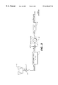
- FIG. 1 is a block diagram of a DS-CDMA receiver constructed in accordance with an embodiment of the present invention.
- FIG. 2 is a block diagram of one of a plurality of multiplier/despreader blocks shown in FIG. 1 .
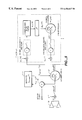
- FIG. 3 is a block diagram of a DS-CDMA receiver, constructed in accordance is with an embodiment of the present invention, that generates a test statistic.
- FIG. 4 shows the comparison of the distances traveled by a signal received by adjacent antennas in an antenna array.
- FIG. 5 is a block diagram of a DS-CDMA receiver, constructed in accordance with an embodiment of the present invention, that includes dithering to enhance stability.
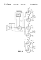
- FIG. 6 is a block diagram of a receiver that implements two step Wiener filtering according to the present invention.
- This specification describes a methods and apparatus pertaining to a DS-CDMA receiver with multiple antennae.
- the present invention is not restricted to DS-CDMA and is not restricted to multiple antennae systems. Instead, it will be appreciated that the present invention is applicable to any receiver that must process a plurality of received signals, whether or not those signals are received over different antennae.
- the present invention may be employed where the multiple signals comprise signals derived from a signal that is applied to a at tapped delay line.
- a “version” of a signal is the signal itself or the result of processing the signal.
- a filtered signal is a version of the signal that has been filtered.
- an “information symbol” is an item of information that it is desired to recover, whether or not the information symbol represents the final information that is provided to the user. For example, data that is recovered from input signals and is then provided to a Viterbi decoder would constitute information symbols even though such data must be decoded.
- One “information symbol” may comprise a plurality of bits. For example, in QPSK, one information symbolt comprises 2 bits of information.
- a “receive path” is a distinct signal path that a receiver is capable of resolving.
- a carrier signal contains a plurality of users' signals; each of these signals is a “receive path.”
- Different fingers for the same user track different signal paths as distinguished by their time of arrival. For example, one finger may track a direct path from a transmitter to the receiver while another finger may track a path wherein a signal bounces off of a building.
- different fingers can be assigned to different transmitters, typically basestations, transmitting the same information symbols but distinguished by a code; this procedure is known as “soft handoff.”
- Section I is an overview of the architecture of an embodiment of a DS-CDMA receiver constructed in accordance with the present invention. As will be described, a plurality of received signals are decorrelated and weights are applied to the decorrelated signals. The weighted decorrelated signals are then summed to derive a symbol estimate.
- Section II develops a framework for mathematically describing multiple antennae receivers and thus for describing a plurality of received signals.
- Section III utilizing the framework developed in Section II, describes the generation of a decorrelation matrix that is used to perform the decorrelation referenced in Section I. In addition, Section III describes methods for generating the weights that are applied to the decorrelated signals.
- Section IV describes an extension to the architecture described in Sections I through III that may be employed where the decorrelation matrix may be poorly conditioned.
- the specific embodiment of the present invention described in Section I is based upon two step Wiener filtering, according to the present invention.
- Section V describes the present invention's use of two step Wiener filtering more generally and then describes an alternate embodiment based on that filtering.
- FIG. 1 is a block diagram of an embodiment of a DS-CDMA multiple antennae receiver for a plurality of users (shown as m users) that employs the present invention's symbol recovery system.
- a plurality of p reception elements shown as a plurality of antennae 10 , receive through a communications channel an input signal that comprises a plurality of received signals ⁇ r 0 (t), r 1 (t) . . . r p ⁇ 1 (t) ⁇ respectively and provide them to a demodulator 12 , which outputs a digital signal time indexed by the letter n.
- the reception elements may comprise, for example, different fiber optic channels or the like or taps of a delay line.
- the output of the demodulator 12 is represented as a vector u before [n], with elements that equal the complex baseband of the signals ⁇ r 0 (t), r 1 (t) . . . r p ⁇ 1 (t) ⁇ after they have been demodulated and sampled.
- a possible composition of vector u before [n] will be more thoroughly described in Section II.
- Vector u before [n] is provided to a decorrelation block 14 , which decorrelates the vector u before [n] by deriving a decorrelation matrix G ⁇ 1 ⁇ 2 [n] that is based on the correlation of the input signal u before [n], as will be further described in Section III, and outputs a vector u after [n], which is the modified (decorrelated) version of the received signals.
- the decorrelation matrix G ⁇ 1 ⁇ 2 [n] is derived from a matrix (hereafter “ ⁇ circumflex over (R) ⁇ [n]”) that represents an estimate of the correlation of the received signals.
- Other types of decorrelation may be used, including without limitation Gramm-Schmidt orthogonalization.
- estimates f i,1 and f i,2 for different fingers are added together by one of the adders 18 .
- the outputs of the fingers must be time aligned.
- only two fingers are shown per user but it will be appreciated that the present invention may be employed with any number of “fingers.”
- the vector u after [n] is processed with information that is specific to the receive path (i.e. fingers 1 and 2 , respectively, for user i) in question.
- the vector u after [n] is decoded (despread with a user specific code in CDMA) by a multiplication/despreader block 16 i , which is one of a plurality of multiplication/despreader blocks 16 0 through 16 2m ⁇ 1 , to create a plurality of initial symbol estimates for the finger in question, one estimate for each of the antennae.
- Each of these initial finger estimates which are represented by vector ⁇ circumflex over (b) ⁇ i [m] in FIG. 2, is multiplied by a weight that is generated from the input signals; essentially, the weight corresponds to the channel response for user i at a particular time delay from a transmitter through the air, the antennae 10 and decorrelation block 14 .
- these weights are represented by a vector w i [m], whose contents will be further described below in this Section and in Section III.
- the weighted estimates are then summed, which results in the symbol estimate f i,1 . (These multiplication and summing operations are depicted in FIG. 2 as the inner product of the vectors ⁇ circumflex over (b) ⁇ i [m] and w i [m]).
- the decorrelation block 14 in FIG. 1 is relatively computationally intensive, it need only be performed once for a particular block of data to produce the vector u after [n]; the generation (update) of the weight vector w i is relatively simple. Thus, a computationally intensive RLS calculation need not be performed once for each of the 2m fingers, thereby decreasing the receiver's hardware requirements. Further, acquisition searches may be performed on the output (u after [n]) of the decorrelation block 14 without a training period, in which case the decorrelation block 14 should output u after [n] essentially continuously.
- the architecture shown in FIG. 1 has many advantageous features. For example, for DS-CDMA systems that employ pilots, the derivation of the weight vector w i is similar to “pilot” or “channel” estimation performed by existing DS-CDMA modems. Therefore, the architecture shown in FIG. 1 may be easily employed in systems that use such modems.
- Still another advantage of the architecture shown in FIG. 1 is that bursty signals, which may suddenly appear, can be very quickly tracked and acquired.
- the bursty signal is a relatively small portion of the total received power
- the switching on and off of this signal modifies the actual correlation matrix R[n] of the received vector only slightly, so that the decorrelation matrix G ⁇ 1 ⁇ 2 [n] changes only slightly.
- the decorrelated vector u after [n] is still nearly decorrelated the instant after a bursted signal begins, even prior to the decorrelating matrix G ⁇ 1 ⁇ 2 [n] having converged to a new decorrelation value.
- the architecture illustrated in FIG. 1 has still further advantageous features.
- the architecture illustrated in FIG. 1 allows for decoupling of the “decorrelation” component from a “pilot recovery” or weight generation component, which may be performed by the multiplication/despreader blocks 16 as will be further described below. That is, these may be two essentially independent processes and could, for example, be carried out on different integrated circuits.
- the performance of the “decorrelation” component and the “pilot recovery” component each can to some extent be analyzed and optimized independently.
- An additional benefit of the decoupling of the “decorrelation” component from the weight generation component is that the more noise sensitive weight generation may be performed in a more computationally intensive way (e.g. with a symbol based pilot filter) than the more complicated “decorrelation.”
- the performance of the receiver is relatively unaffected by the eigenvalue spread of the received correlation matrix ⁇ circumflex over (R) ⁇ [n].
- modifications to the decorrelation block 14 can be made to compensate for poor conditioning with no consideration in the recovery stage to the conditioning.
- each demodulation path can remain unaware of any conditioning effects.
- floating point or complicated fixed point computation may be performed by the decorrelation block 14 , which, in the preferred embodiment, obviates the need to perform such complicated computations in the signal recovery stage implemented by the multiplication/despreader blocks 16 .
- the output u after [n] of the decorrelation block 14 is a vector of signals with equal and known complex baseband. There will be no time variation of the power of these signals, and considering the spread nature of the signal a small number of bits can be used to represent the input signals at this point.
- FIG. 2 is a block diagram of the multiplication block for a DS-CDMA receiver that employs pilot signals.
- a pilot signal is a signal transmitted to a receiver but also known a priori; the receiver may thus estimate the channel response by comparing the received pilot signal to the known value.
- the symbol estimate f i,1 is derived by a multiplier/summer 20 that takes the inner product of a weight w i and a despread (decoded) version ⁇ circumflex over (b) ⁇ i [n] of the vector u after [n].
- the despread (decoded) version ⁇ circumflex over (b) ⁇ i [n] of the vector u after [n] represents a plurality of initial estimates, one estimate for each of the p antennae, of the desired information symbol f i,1 .
- Each of these initial estimates is multiplied by one of the weights w i , which is derived from an estimate of a pilot signal P i , as will be further described in Section III.
- the estimate of the pilot signal p i and the despread version ⁇ circumflex over (b) ⁇ i [n] of the vector u after [n] are derived from the vector u after [n] by multipliers 26 and 28 , respectively, which multiply u after [n] by the complex conjugates of a despreading code c i and the known pilot signal p i .
- the results are accumulated by accumulators 22 and 24 , respectively, over one information symbol period, and then cleared from the pertinent accumulator in preparation for the next symbol period.
- the estimate of the pilot signal p i is then provided to a filter 30 , which may be a simple Infinite Impulse Response (IIR) filter or a Finite Impulse Response (FIR) filter, which implements the filtering described in Section III on a symbol sample rate basis as will be further described in Section III, to derive the weights w i .
- the vector w i is transposed by a transposer 32 and the inner product of the transposed w i and vector b i [n] is generated by the multiplier/summer 20 as previously described, resulting in one finger's estimate f i,1 for an information symbol for user i.
- FIG. 3 is a simplified block diagram of a receiver according to the present invention that includes the generation of a simple test statistic, used to compare to a threshold or to other test statistics to determine if the particular code and code timing applied is valid.
- the signal u after [n] which may be generated in the manner previously described, is provided to a multiplier 34 which multiplies u after [n] by the complex conjugate of a pilot signal p 0 and the resulting vector is accumulated by accumulator 36 over a symbol period.
- the result is provided to multiplier/summer 38 , which generates the inner product of the resulting vector and its transposition to generate a test statistic.
- FIG. 4 In a receiver with multiple antennae, the spacing of the antennae will result in different antennae receiving the identical signal at different times, as illustrated in FIG. 4 .
- an antenna element is assumed to be at each point marked (m)d, where m is an integer.
- FIG. 4 assumes an equal distance between each antenna, it will be appreciated that the present invention is not limited to such equal length schemes nor is it limited to linear arrays; any other antenna geometry (e.g. circular arrays) may be used.
- each antenna element receives a version of the signal delayed by the additional distance traveled, so that using the left most element as the reference and considering the geometry shown in FIG. 4, for p elements indexed 0:(p ⁇ 1), the value of the received signal at an element m is a delayed (or advanced) version of the received signal at element 0 as follows:
- the received signal is a carrier modulated by a complex baseband signal s(t), with the carrier frequency being ⁇ /2 ⁇ Hz.
- the received signal is:
- r m ( t ) exp( j ⁇ ( t ⁇ m ⁇ d ⁇ cos( ⁇ ))) ⁇ s ( t ⁇ m d ⁇ cos( ⁇ )).
- r ( t ) (s i ( t ) ⁇ d i + ⁇ j not equal to i s j ( t ) d j +v ( t )) ⁇ exp( j ⁇ t)
- Each antenna signal is downconverted to baseband to remove the carrier, and its complex baseband sampled to give the vector u before [n] as follows:
- n is an integer.
- b i [n/K] the over sampled information symbols transmitted (sampled at the chip rate, so that b[n/K] is constant over one symbol comprised of K chips);
- This section describes the decorrelation performed by the decorrelation block 14 shown in FIG. 1 and the derivation of the weights w i .
- the decorrelation block 14 is then described.
- a general formula for the weights is described, followed by a more specific formula for the weights w i for a DS-CDMA system.
- an alternative formula for the weights w i is then derived for a DS-CDMA system that employs a pilot signal, which formula may be implemented by the filter 30 shown in FIG. 2 .
- the decorrelation block 14 creates the vector u after [n] based upon the value of u before [n]. In particular:
- G ⁇ 1 ⁇ 2 [n] which is a matrix derived by the decorrelation block 14 , is the Cholesky decomposition of an estimated correlation matrix ⁇ circumflex over (R) ⁇ [n] which represents the correlation of the input signals represented by the vector u before .
- ⁇ circumflex over (R) ⁇ [n] is generated by performing steps derived from standard RLS methodology, which involves generating ⁇ circumflex over (R) ⁇ [n] based upon values of ⁇ circumflex over (R) ⁇ [n ⁇ 1].
- the annihilation of the upper right vector can be performed with a series of Givens rotations (see [Haykin,. 1996] or [Golub, 1996]). Each rotation is a unitary transformation, and the product of the rotations is thus unitary.
- the Givens rotation is performed by post-multiplication by a Givens matrix. The matrix differs from the identity only in 4 entries, falling at the four comers defined by 2 rows and 2 columns, as shown below for a Givens matrix U.
- the upper right vector is annihilated one entry at a time, using p (where p is the number of reception elements) rotation matrices with s and c properly determined and obeying the constraints:
- G ⁇ 1 ⁇ 2 [n] may then be obtained simply by scaling ⁇ ⁇ 1 ⁇ 2 [n] .
- Systolic array implementations to perform this kind of operation exist can be found in [Haykin, 1996].
- the rotations can be performed so as to maintain the triangular nature of G ⁇ 1 ⁇ 2 [n], thereby decreasing the required number of calculations.
- Obtaining The proper selection of the rotations also ensures that the diagonal of the lower triangular matrix is positive, which is the unique Cholesky decomposition solution. Maintaining the triangularity and maintaining the positive diagonal are important, the first to minimize calculations and the latter to provide less time variation in the structure of the matrix, which is helpful in connection with various operations described herein.
- the output signal for a user i is equal to a vector u after [n] multiplied by a weight vector w i .
- the output signal y i [n] for a user i is equal to w i H u after [n] (where the superscript H denotes the Hermetian transposition of a matrix), where the weights w 1 are equal to:
- ⁇ is an exponential “forgetting factor”
- v i [n] is the desired symbol (i.e. the signal transmitted from a transmitter) for user i at interval n.
- the above equations are modified RLS equations where the assumption has been made that the scaled RLS sample correlation matrix is the identity matrix.
- the weights for a particular user i are based on a cross correlation between the decorrelated vector u after and the desired signal, weighted by a simple exponential filter.
- a simple exponential filter has been used above, any filtering shape desired can be applied.
- the exponential forgetting factor is commonly applied because it is the lowest complexity method, lending itself to the simplified recursions of RLS.
- the weights are equal to:
- the calculation of the weights w i depends upon the value of the desired signal, which as mentioned above is not known precisely by the receiver.
- a pilot signal may be used to derive the weights. Pilot signals are provided in coherent communications to facilitate channel estimation in the receiver. In DS-CDMA systems, this pilot may be time multiplexed or code multiplexed with the data signal. As long as the time multiplexing period is small enough to capture channel variations, there is no substantial difference between the two methods in terms of performance or applicability of the presently described system. For notational simplicity, a code multiplexed pilot will be assumed but it will be appreciated that the present invention may be employed where the pilot is time multiplexed with the data signal.
- the Wiener filter derived by using a pilot differs from that derived given the exact desired sequence (the data) by a constant factor, given by the square root of the ratio of transmit power of the pilot to that of the data channel.
- the weights are equal to:
- the desired signal v i [n] for a user i may be taken as equal to the pilot signal p i [n] for that user, in which case, w i [n] becomes
- the equation for z i [n] indicates that the weights w i may be derived by passing the accumulation of the signal u after [k]p i *[k], which is provided by the output of the accumulator 22 in FIG. 2, through an appropriate filter and the filter 30 may be designed accordingly. As will be further described below, since the accumulator 22 provides a despread version of the signal u after [k]p i *[k], the filter 30 may operate at the symbol rate.
- the filter 30 may be designed a priori based upon assumed channel conditions or it may be adaptively adjusted by means such as RLS or LMS.
- the filter 30 need not be the exponential weighting of ⁇ inherited from standard RLS but may be any desired filtering shape. The exponential weighting is commonly applied because it is the lowest complexity method, lending itself to the simplified recursions of RLS.
- the sample crosscorrelation u after [n] ⁇ p i *[n] is being filtered by a filter impulse response equivalent to a single tap IIR (Infinite Impulse Response) filter. Since the ideal value for the weight is given by E ⁇ u after [n] ⁇ p i *[n] ⁇ , the problem may be considered to be the estimation of the value of E ⁇ u after [n] ⁇ p i *[n] ⁇ . This estimation can in general be performed better with a filter response h[n] optimized for the statistics of the time varying channel. Thus, the calculation of w i [n] may be generalized to any filtering of the sample crosscorrelation.
- the finger index i has been omitted.
- the index “m” is a time index at the symbol rate and the “symb” subscript explicitly denotes a symbol based sample rate, as opposed to the chip based sample rates used elsewhere in the document. (From Section II, there are K chips in an information symbol.)
- the combination of the accumulate and dump operation and filtering at the symbol rate is effectively the same as filtering the chip-rate pilot crosscorrelation (u after [n] ⁇ p i *[n]) by a square filter response of length equal to the duration of a symbol, and decimating to reduce the processing sample rate to the symbol rate.
- the decoupling of the processing of the sample correlation matrix ⁇ [n] from the processing of the crosscorrelation makes this particularly easy.
- weights w i and G ⁇ 1 ⁇ 2 d indicate that the weights w i are essentially an estimate the channel response; thus, the pilot signal has been used to estimate the channel response.
- the weights are based on a cross correlation between the decorrelated vector u after and the desired signal, this cross correlation need not be explicitly performed if, for example, a pilot is available to replace the desired signal in the cross-correlation.
- the rank of the matrix R[n] described in Section III will be given by the number of signals impinging on the antenna array 10 , as each such signal contributes to some new mode. If there are more such signals than there are antennae, then the problem will be overconstrained, allowing for the unique solutions discussed. If there are fewer signals than antennae, then the correlation matrix R[n] will not be invertible, and the system described above may be unstable. In practice, thermal noise will be uncorrelated from antenna to antenna and may thus assure the correlation matrix R[n] is full rank. However, while the matrix R[n] will not be singular it may still provide very poor conditioning of the matrix ⁇ circumflex over (R) ⁇ [n], leaving the system unstable.
- thermal noise provides a full rank matrix
- the level of that thermal noise is typically low enough as to not help provide adequate conditioning of the matrix ⁇ circumflex over (R) ⁇ [n].
- ADC Analog to Digital Converter
- the ADC quantization noise may also be highly correlated, still leaving the correlation matrix ⁇ circumflex over (R) ⁇ [n] ill-conditioned.
- FIG. 5 is a block diagram of an alternate embodiment of the present invention that may be used for systems where ⁇ circumflex over (R) ⁇ [n] would otherwise be poorly conditioned.
- the vector u before [n] is provided to a summer 40 , where it is added to a randomized dither signal dt[n] to create a vector u intermediate [n].
- the matrix G ⁇ 1 ⁇ 2 [n] is derived according to Section III based upon u intermediate [n] by decorrelation block 14 , and the inner product of this matrix and u before [n] results in u after [n], which is produced by adder/summer 42 .
- the signal u after [n] is then processed as described with reference to FIG. 2 .
- the elements of d are chosen to be decorrelated with each other and of equal power ⁇ 2 , so that
- ⁇ 2 can be selected as the smallest number which guarantees acceptable conditioning. Usually dt will consist of a series of +-1s modulating the least significant bit. If the selected value of ⁇ 2 is too small to be realized with the given number of bits, it can be added periodically rather than every sample, to reduce its average power.
- d can be selected in many ways. For example, it may or may not be pseudo-random. If d cycles through the non-random sequence:
- ⁇ diag( ⁇ 0 , ⁇ 1 . . . ⁇ N ⁇ 1 ) is the eigen value matrix
- ⁇ i is the ith eigen value (these are usually ordered from the largest to the smallest)
- condition number goes to infinity.
- condition number the worse the conditioning of the matrix and the harder it is to correctly invert the matrix.
- Section I The specific embodiment of the present invention described in Section I is based upon two step Wiener filtering, according to the present invention. This Section describes the present invention's use of two step Wiener filtering more generally and then describes an alternate embodiment based on that filtering.
- R[n] is the correlation matrix that represents the correlation of the received signals u[n]
- p[n] is the crosscorrelation between a desired signal and the received signal.
- an estimate ⁇ circumflex over (R) ⁇ ⁇ 1 [n] of the matrix R ⁇ 1 [n] need only be calculated once (for a time n).
- the estimate ⁇ circumflex over (R) ⁇ ⁇ 1 [n] may then be employed to generate a plurality of symbol estimates for a corresponding plurality of signal paths.
- the weights for a particular symbol path i may be taken as ⁇ circumflex over (R) ⁇ ⁇ 1 [n]p i [n], where p i [n] is the cross correlation between a desired signal for path i and the input signal u[n].
- the symbol estimate for path i is then generated by multiplying these weights by the input signal u[n].
- a plurality of p reception elements shown as a plurality of antennae 50 , receive through a communications channel an input signal that comprises a plurality of received signals ⁇ r 0 (t), r 1 (t) . . . r p ⁇ 1 (t) ⁇ respectively and provide them to a demodulator 52 , which outputs a digital signal time indexed by the letter n.
- the reception elements may comprise, for example, different fiber optic channels or the like or taps of a delay line.
- the output of the demodulator 52 is represented as a vector u before , with elements that equal the complex baseband of the signals ⁇ r 0 (t), r 1 (t) . . . r p ⁇ 1 (t) ⁇ after they have been demodulated and sampled.
- a possible composition of vector u before [n] is more thoroughly described in Section II.
- Vector u before [n] is provided to a calculation block 54 , which generates a matrix that is based on the correlation of the input signal u before [n].
- calculation block 54 derives an estimate ⁇ circumflex over (R) ⁇ ⁇ 1 [n] that is based on the correlation of the input signal u before [n] of the inverse of the correlation matrix ⁇ circumflex over (R) ⁇ [n].
- the finger symbol estimates are added together by one of a plurality of adders 58 to generate the symbol estimate for that user.
- the entire Wiener filtering process need not be separately performed for each signal path.
- ⁇ circumflex over (R) ⁇ ⁇ 1 [n] may be generated once (for a particular time n) and the result applied to each signal path.
- the architecture illustrated in FIG. 6 may be implemented with RLS filtering, in which case ⁇ circumflex over (R) ⁇ ⁇ 1 [n] may be generated as follows:
- the weights w i [n] for signal path i may be generated as follows:
- w i [n] w i [n ⁇ 1 ]+k[n ]( d i *[n; ] ⁇ u ⁇ H [n]w i [n -1]).
- the pilot signal for signal path i may be used as the desired signal.
Abstract
Description


Claims (45)
Priority Applications (1)
| Application Number | Priority Date | Filing Date | Title |
|---|---|---|---|
| US09/212,853 US6456647B1 (en) | 1998-12-16 | 1998-12-16 | Two step signal recovery scheme for a receiver |
Applications Claiming Priority (1)
| Application Number | Priority Date | Filing Date | Title |
|---|---|---|---|
| US09/212,853 US6456647B1 (en) | 1998-12-16 | 1998-12-16 | Two step signal recovery scheme for a receiver |
Publications (1)
| Publication Number | Publication Date |
|---|---|
| US6456647B1 true US6456647B1 (en) | 2002-09-24 |
Family
ID=22792661
Family Applications (1)
| Application Number | Title | Priority Date | Filing Date |
|---|---|---|---|
| US09/212,853 Expired - Lifetime US6456647B1 (en) | 1998-12-16 | 1998-12-16 | Two step signal recovery scheme for a receiver |
Country Status (1)
| Country | Link |
|---|---|
| US (1) | US6456647B1 (en) |
Cited By (14)
| Publication number | Priority date | Publication date | Assignee | Title |
|---|---|---|---|---|
| US6704322B1 (en) * | 1999-11-17 | 2004-03-09 | National Science Council | Smart different prime code multiplexing system |
| US20040048580A1 (en) * | 2001-06-21 | 2004-03-11 | Tim Lunn | Base transceiver station |
| US20040062217A1 (en) * | 2002-09-30 | 2004-04-01 | Farrokh Abrishamkar | Method and apparatus for pilot estimation using an adaptive prediction error method with a kalman filter and a gauss-newton algorithm |
| US20040185787A1 (en) * | 2003-03-03 | 2004-09-23 | Andreas Molisch | Estimating channel impulse response and equalizer coefficients in UWB communication systems |
| US20050071800A1 (en) * | 2000-03-01 | 2005-03-31 | Realtek Semiconductor Corporation | Mixed hardware/sofware architecture and method for processing xDSL communications |
| US20050101353A1 (en) * | 2003-09-25 | 2005-05-12 | Interdigital Technology Corporation | Method and system for enhancing reception of wireless communication signals |
| US20050111414A1 (en) * | 2000-03-21 | 2005-05-26 | Liberti Joseph C.Jr. | Parallel interference cancellation and minimum cost channel estimation |
| US20050186921A1 (en) * | 2004-02-24 | 2005-08-25 | Hoo Min C. | Method and system for antenna selection diversity with prediction |
| US20050265433A1 (en) * | 1999-04-02 | 2005-12-01 | Yukihiko Okumura | Channel estimation device and method, demodulation device and method, and fading frequency decision device and method |
| US7002939B1 (en) * | 1999-08-27 | 2006-02-21 | Matsushita Electric Industrial Co., Ltd. | Communication terminal device and channel estimating method |
| US7042928B2 (en) * | 2002-10-23 | 2006-05-09 | Qualcomm Incorporated | Method and apparatus for pilot estimation using prediction error method |
| US20080075150A1 (en) * | 2000-02-23 | 2008-03-27 | Interdigital Technology Corporation | Reverse link correlation filter in wireless communication systems |
| US20080285675A1 (en) * | 2005-10-28 | 2008-11-20 | Koninklijke Philips Electronics, N.V. | Multiple Antenna Transmission with Variable Diversity Gain |
| US20100142612A1 (en) * | 2003-08-21 | 2010-06-10 | Pieter Van Rooyen | Method and system for increasing data rate in a mobile terminal using spatial multiplexing for dvb-h communication |
Citations (5)
| Publication number | Priority date | Publication date | Assignee | Title |
|---|---|---|---|---|
| US5414699A (en) * | 1993-09-27 | 1995-05-09 | Motorola, Inc. | Method and apparatus for receiving and decoding communication signals in a CDMA receiver using partial de-correlation |
| US5724378A (en) * | 1994-12-13 | 1998-03-03 | Nit Mobile Communications Network, Inc. | CDMA multiuser receiver and method |
| US5809020A (en) * | 1996-03-18 | 1998-09-15 | Motorola, Inc. | Method for adaptively adjusting weighting coefficients in a cDMA radio receiver |
| US6069912A (en) * | 1995-11-29 | 2000-05-30 | Ntt Mobile Communications Network, Inc. | Diversity receiver and its control method |
| US6304750B1 (en) * | 1998-11-06 | 2001-10-16 | Lucent Technologies Inc. | Space-time diversity receiver for wireless systems |
-
1998
- 1998-12-16 US US09/212,853 patent/US6456647B1/en not_active Expired - Lifetime
Patent Citations (5)
| Publication number | Priority date | Publication date | Assignee | Title |
|---|---|---|---|---|
| US5414699A (en) * | 1993-09-27 | 1995-05-09 | Motorola, Inc. | Method and apparatus for receiving and decoding communication signals in a CDMA receiver using partial de-correlation |
| US5724378A (en) * | 1994-12-13 | 1998-03-03 | Nit Mobile Communications Network, Inc. | CDMA multiuser receiver and method |
| US6069912A (en) * | 1995-11-29 | 2000-05-30 | Ntt Mobile Communications Network, Inc. | Diversity receiver and its control method |
| US5809020A (en) * | 1996-03-18 | 1998-09-15 | Motorola, Inc. | Method for adaptively adjusting weighting coefficients in a cDMA radio receiver |
| US6304750B1 (en) * | 1998-11-06 | 2001-10-16 | Lucent Technologies Inc. | Space-time diversity receiver for wireless systems |
Cited By (33)
| Publication number | Priority date | Publication date | Assignee | Title |
|---|---|---|---|---|
| US8295332B2 (en) | 1999-04-02 | 2012-10-23 | Ntt Docomo, Inc. | Channel estimation device and method, demodulation device and method, and fading frequency decision device and method |
| US20110142102A1 (en) * | 1999-04-02 | 2011-06-16 | Ntt Docomo, Inc. | Channel estimation device and method, demodulation device and method, and fading frequency decision device and method |
| US7301991B2 (en) * | 1999-04-02 | 2007-11-27 | Ntt Docomo, Inc. | Fading frequency decision device and method |
| US20050265433A1 (en) * | 1999-04-02 | 2005-12-01 | Yukihiko Okumura | Channel estimation device and method, demodulation device and method, and fading frequency decision device and method |
| US7002939B1 (en) * | 1999-08-27 | 2006-02-21 | Matsushita Electric Industrial Co., Ltd. | Communication terminal device and channel estimating method |
| US6704322B1 (en) * | 1999-11-17 | 2004-03-09 | National Science Council | Smart different prime code multiplexing system |
| US7613227B2 (en) * | 2000-02-23 | 2009-11-03 | Ipr Licensing, Inc. | Reverse link correlation filter in wireless communication systems |
| US20080075150A1 (en) * | 2000-02-23 | 2008-03-27 | Interdigital Technology Corporation | Reverse link correlation filter in wireless communication systems |
| US20050071800A1 (en) * | 2000-03-01 | 2005-03-31 | Realtek Semiconductor Corporation | Mixed hardware/sofware architecture and method for processing xDSL communications |
| US8325751B2 (en) * | 2000-03-01 | 2012-12-04 | Realtek Semiconductor Corp. | Mixed hardware/software architecture and method for processing communications |
| US8670418B2 (en) | 2000-03-21 | 2014-03-11 | Tti Inventions C Llc | Successive interference cancellation |
| US7688777B2 (en) * | 2000-03-21 | 2010-03-30 | Liberti Jr Joseph Charles | Combined adaptive spatio-temporal processing and multi-user detection for CDMA wireless systems |
| US20050128985A1 (en) * | 2000-03-21 | 2005-06-16 | Liberti Joseph C.Jr. | Combined adaptive spatio-temporal processing and multi-user detection for CDMA wireless systems |
| US8111669B2 (en) | 2000-03-21 | 2012-02-07 | Telcordia Licensing Company Llc | Parallel interference cancellation and minimum cost channel estimation |
| US20050111414A1 (en) * | 2000-03-21 | 2005-05-26 | Liberti Joseph C.Jr. | Parallel interference cancellation and minimum cost channel estimation |
| US20040048580A1 (en) * | 2001-06-21 | 2004-03-11 | Tim Lunn | Base transceiver station |
| US20040062217A1 (en) * | 2002-09-30 | 2004-04-01 | Farrokh Abrishamkar | Method and apparatus for pilot estimation using an adaptive prediction error method with a kalman filter and a gauss-newton algorithm |
| US7042928B2 (en) * | 2002-10-23 | 2006-05-09 | Qualcomm Incorporated | Method and apparatus for pilot estimation using prediction error method |
| US7356100B2 (en) * | 2003-03-03 | 2008-04-08 | Mitsubishi Electric Research Laboratories, Inc. | Estimating channel impulse response and equalizer coefficients in UWB communication systems |
| US20040185787A1 (en) * | 2003-03-03 | 2004-09-23 | Andreas Molisch | Estimating channel impulse response and equalizer coefficients in UWB communication systems |
| US8027704B2 (en) * | 2003-08-21 | 2011-09-27 | Broadcom Corporation | Method and system for increasing data rate in a mobile terminal using spatial multiplexing for DVB-H communication |
| US20100142612A1 (en) * | 2003-08-21 | 2010-06-10 | Pieter Van Rooyen | Method and system for increasing data rate in a mobile terminal using spatial multiplexing for dvb-h communication |
| US20050101353A1 (en) * | 2003-09-25 | 2005-05-12 | Interdigital Technology Corporation | Method and system for enhancing reception of wireless communication signals |
| US7340281B2 (en) * | 2003-09-25 | 2008-03-04 | Interdigital Technology Corporation | Method and system for enhancing reception of wireless communication signals |
| US20050186921A1 (en) * | 2004-02-24 | 2005-08-25 | Hoo Min C. | Method and system for antenna selection diversity with prediction |
| US7917116B2 (en) | 2004-02-24 | 2011-03-29 | Broadcom Corporation | Method and system for antenna selection diversity with prediction |
| US20090270060A1 (en) * | 2004-02-24 | 2009-10-29 | Min Chuin Hoo | Method and system for antenna selection diversity with prediction |
| US7558554B2 (en) * | 2004-02-24 | 2009-07-07 | Broadcom Corporation | Method and system for antenna selection diversity with prediction |
| US8335272B2 (en) * | 2005-10-28 | 2012-12-18 | Koninklijke Philips Electronics N.V. | Multiple antenna transmission with variable diversity gain |
| TWI410063B (en) * | 2005-10-28 | 2013-09-21 | Koninkl Philips Electronics Nv | Multiple antenna transmission with variable diversity gain |
| US20080285675A1 (en) * | 2005-10-28 | 2008-11-20 | Koninklijke Philips Electronics, N.V. | Multiple Antenna Transmission with Variable Diversity Gain |
| US9325404B2 (en) | 2005-10-28 | 2016-04-26 | Koninklijke Philips N.V. | Multiple antenna transmission with variable diversity gain |
| US9768846B2 (en) | 2005-10-28 | 2017-09-19 | Koninklijke Philips N.V. | Multiple antenna transmission with variable diversity gain |
Similar Documents
| Publication | Publication Date | Title |
|---|---|---|
| JP4847874B2 (en) | Multi-user adaptive array receiver and method | |
| US6363104B1 (en) | Method and apparatus for interference cancellation in a rake receiver | |
| US6426973B1 (en) | Differential minimum mean squared error communication signal compensation method | |
| US6745050B1 (en) | Multichannel multiuser detection | |
| Wang et al. | Blind multiuser detection: A subspace approach | |
| US6801565B1 (en) | Multi-stage rake combining methods and apparatus | |
| US6456647B1 (en) | Two step signal recovery scheme for a receiver | |
| US7061970B2 (en) | Self-synchronizing adaptive multistage receiver for wireless communication systems | |
| WO2006092090A1 (en) | A method and equipment for realizing smart antenna in wcdma system | |
| KR20000016990A (en) | Detectors for cdma systems | |
| US7167529B2 (en) | Method and device for radio signal reception | |
| US20030146870A1 (en) | Apparatus for an methods of receiving a transmission signal | |
| US20030142762A1 (en) | Wireless receiver method and apparatus using space-cover-time equalization | |
| US7079607B2 (en) | Multi-user detection method | |
| US7310394B2 (en) | LMMSE-based RAKE receiver with channel tap assignment | |
| KR100818465B1 (en) | Rake-based cdma receivers for multiple receiver antennas | |
| US7376106B2 (en) | Code-division-multiple-access (DS-CDMA) channels with aperiodic codes | |
| US8259854B2 (en) | Channel estimation using common and dedicated pilots | |
| US7161975B2 (en) | Enhancing CDMA multiuser detection by constraining soft decisions | |
| Hu et al. | Space-time adaptive reduced-rank multistage Wiener filtering for asynchronous DS-CDMA | |
| US7127013B2 (en) | Spacetime equalization in a wireless receiver | |
| US6993064B2 (en) | Multi-user receiving method and receiver | |
| Thompson et al. | Algorithms for coherent diversity combining of M-ary orthogonal signals | |
| Chen et al. | A RAKE receiver design for WCDMA FDD uplink with an RLS-based adaptive beamforming scheme | |
| Lin et al. | A low-complexity multi-user CDMA receiver with blind channel estimation and partially adaptive MAI suppression |
Legal Events
| Date | Code | Title | Description |
|---|---|---|---|
| STCF | Information on status: patent grant |
Free format text: PATENTED CASE |
|
| FPAY | Fee payment |
Year of fee payment: 4 |
|
| FEPP | Fee payment procedure |
Free format text: PAYER NUMBER DE-ASSIGNED (ORIGINAL EVENT CODE: RMPN); ENTITY STATUS OF PATENT OWNER: LARGE ENTITY Free format text: PAYOR NUMBER ASSIGNED (ORIGINAL EVENT CODE: ASPN); ENTITY STATUS OF PATENT OWNER: LARGE ENTITY |
|
| FPAY | Fee payment |
Year of fee payment: 8 |
|
| FPAY | Fee payment |
Year of fee payment: 12 |
|
| AS | Assignment |
Owner name: DEUTSCHE BANK AG NEW YORK BRANCH, AS COLLATERAL AG Free format text: PATENT SECURITY AGREEMENT;ASSIGNORS:LSI CORPORATION;AGERE SYSTEMS LLC;REEL/FRAME:032856/0031 Effective date: 20140506 |
|
| AS | Assignment |
Owner name: AVAGO TECHNOLOGIES GENERAL IP (SINGAPORE) PTE. LTD Free format text: ASSIGNMENT OF ASSIGNORS INTEREST;ASSIGNOR:LSI CORPORATION;REEL/FRAME:035390/0388 Effective date: 20140814 |
|
| AS | Assignment |
Owner name: LSI CORPORATION, CALIFORNIA Free format text: TERMINATION AND RELEASE OF SECURITY INTEREST IN PATENT RIGHTS (RELEASES RF 032856-0031);ASSIGNOR:DEUTSCHE BANK AG NEW YORK BRANCH, AS COLLATERAL AGENT;REEL/FRAME:037684/0039 Effective date: 20160201 Owner name: AGERE SYSTEMS LLC, PENNSYLVANIA Free format text: TERMINATION AND RELEASE OF SECURITY INTEREST IN PATENT RIGHTS (RELEASES RF 032856-0031);ASSIGNOR:DEUTSCHE BANK AG NEW YORK BRANCH, AS COLLATERAL AGENT;REEL/FRAME:037684/0039 Effective date: 20160201 |
|
| AS | Assignment |
Owner name: BANK OF AMERICA, N.A., AS COLLATERAL AGENT, NORTH CAROLINA Free format text: PATENT SECURITY AGREEMENT;ASSIGNOR:AVAGO TECHNOLOGIES GENERAL IP (SINGAPORE) PTE. LTD.;REEL/FRAME:037808/0001 Effective date: 20160201 Owner name: BANK OF AMERICA, N.A., AS COLLATERAL AGENT, NORTH Free format text: PATENT SECURITY AGREEMENT;ASSIGNOR:AVAGO TECHNOLOGIES GENERAL IP (SINGAPORE) PTE. LTD.;REEL/FRAME:037808/0001 Effective date: 20160201 |
|
| AS | Assignment |
Owner name: AVAGO TECHNOLOGIES GENERAL IP (SINGAPORE) PTE. LTD., SINGAPORE Free format text: TERMINATION AND RELEASE OF SECURITY INTEREST IN PATENTS;ASSIGNOR:BANK OF AMERICA, N.A., AS COLLATERAL AGENT;REEL/FRAME:041710/0001 Effective date: 20170119 Owner name: AVAGO TECHNOLOGIES GENERAL IP (SINGAPORE) PTE. LTD Free format text: TERMINATION AND RELEASE OF SECURITY INTEREST IN PATENTS;ASSIGNOR:BANK OF AMERICA, N.A., AS COLLATERAL AGENT;REEL/FRAME:041710/0001 Effective date: 20170119 |
|
| AS | Assignment |
Owner name: AVAGO TECHNOLOGIES INTERNATIONAL SALES PTE. LIMITE Free format text: MERGER;ASSIGNOR:AVAGO TECHNOLOGIES GENERAL IP (SINGAPORE) PTE. LTD.;REEL/FRAME:047195/0026 Effective date: 20180509 |
|
| AS | Assignment |
Owner name: AVAGO TECHNOLOGIES INTERNATIONAL SALES PTE. LIMITE Free format text: CORRECTIVE ASSIGNMENT TO CORRECT THE EFFECTIVE DATE OF MERGER PREVIOUSLY RECORDED ON REEL 047195 FRAME 0026. ASSIGNOR(S) HEREBY CONFIRMS THE MERGER;ASSIGNOR:AVAGO TECHNOLOGIES GENERAL IP (SINGAPORE) PTE. LTD.;REEL/FRAME:047477/0423 Effective date: 20180905 |