US6421700B1 - Method and system for work process support using independent system and user states - Google Patents
Method and system for work process support using independent system and user states Download PDFInfo
- Publication number
- US6421700B1 US6421700B1 US09/091,366 US9136699A US6421700B1 US 6421700 B1 US6421700 B1 US 6421700B1 US 9136699 A US9136699 A US 9136699A US 6421700 B1 US6421700 B1 US 6421700B1
- Authority
- US
- United States
- Prior art keywords
- activity
- user
- state
- states
- system state
- Prior art date
- Legal status (The legal status is an assumption and is not a legal conclusion. Google has not performed a legal analysis and makes no representation as to the accuracy of the status listed.)
- Expired - Lifetime
Links
- 238000000034 method Methods 0.000 title claims abstract description 157
- 230000008569 process Effects 0.000 title claims abstract description 90
- 230000000694 effects Effects 0.000 claims abstract description 290
- 230000008859 change Effects 0.000 claims description 27
- 238000012545 processing Methods 0.000 claims description 20
- 230000004044 response Effects 0.000 claims description 6
- 230000007246 mechanism Effects 0.000 abstract description 16
- 230000004075 alteration Effects 0.000 abstract description 2
- 238000010200 validation analysis Methods 0.000 description 12
- 238000010586 diagram Methods 0.000 description 11
- 230000003993 interaction Effects 0.000 description 7
- 238000013459 approach Methods 0.000 description 6
- 230000006399 behavior Effects 0.000 description 6
- 230000008901 benefit Effects 0.000 description 4
- 230000004048 modification Effects 0.000 description 3
- 238000012986 modification Methods 0.000 description 3
- 238000013475 authorization Methods 0.000 description 2
- 238000013500 data storage Methods 0.000 description 2
- 230000014509 gene expression Effects 0.000 description 2
- 230000000977 initiatory effect Effects 0.000 description 2
- 238000012552 review Methods 0.000 description 2
- 102000006947 Histones Human genes 0.000 description 1
- 108010033040 Histones Proteins 0.000 description 1
- 230000009471 action Effects 0.000 description 1
- 150000001875 compounds Chemical class 0.000 description 1
- 238000012217 deletion Methods 0.000 description 1
- 230000037430 deletion Effects 0.000 description 1
- 238000005516 engineering process Methods 0.000 description 1
- 230000006870 function Effects 0.000 description 1
- 238000013507 mapping Methods 0.000 description 1
- 230000003287 optical effect Effects 0.000 description 1
- 230000003252 repetitive effect Effects 0.000 description 1
- 230000009897 systematic effect Effects 0.000 description 1
- 230000009466 transformation Effects 0.000 description 1
- 238000000844 transformation Methods 0.000 description 1
Images


Classifications
-
- G—PHYSICS
- G06—COMPUTING; CALCULATING OR COUNTING
- G06Q—INFORMATION AND COMMUNICATION TECHNOLOGY [ICT] SPECIALLY ADAPTED FOR ADMINISTRATIVE, COMMERCIAL, FINANCIAL, MANAGERIAL OR SUPERVISORY PURPOSES; SYSTEMS OR METHODS SPECIALLY ADAPTED FOR ADMINISTRATIVE, COMMERCIAL, FINANCIAL, MANAGERIAL OR SUPERVISORY PURPOSES, NOT OTHERWISE PROVIDED FOR
- G06Q10/00—Administration; Management
- G06Q10/10—Office automation; Time management
Definitions
- This invention relates to data processing, and more particularly to a systems and methods supporting processes involving activities such as generation, alteration, distribution, authentication and validation of documents. More particularly, the invention concerns such systems and methods providing representing and reasoning with independent user and system states for activities within a process, using typed dependencies to describe relationships between activities, and/or providing resolution of conflicts between what a user wants to do and a predetermined model of the activities.
- the present invention provides a method carried out in a data processing system involving at least one activity, the activity being performed by at least one user, comprising: for the or each activity, assigning a user state from one of a plurality of user states, and assigning a system state from one of a plurality of system states, the system state and the user state being independent.
- the method may include the step of changing the system state of the activity in response to a change in the user state, and vice versa.
- the method may relate to at least a first and a second activity, each activity being performed by at least one user, the method comprising: for each activity, assigning a user state from one of a plurality of user states, and assigning a system state from one of a plurality of system states, the system state and the user state being independent, and changing the user state and/or system state of the second activity when the user state and/or system state of the first activity satisfy a predetermined condition.
- the invention addresses the aforementioned problems by representing and reasoning with descriptions of what the user is actually doing as well as an idealised representation of the work.
- An advantage of the invention is that this arrangement allows deviations from the normative process to be carried out routinely while maintaining a representation of any discrepancies between what is “supposed” to happen (according to a predetermined model of the process) and what is, “really” happening.
- the invention improves flexibility by introducing a mechanism to support reasoning over the process flow using a parallel set of system and user states, so that the discrepancies can be used to maintain a record of any mismatch.
- the present invention further provides a method, carried out in a data processing system, involving at least a first and a second activity, each activity being performed by at least one user, comprising: for each activity, defining a relationship between that activity and the or each other activity, said relationship being one of a plurality of predetermined different relationships.
- each activity has a plurality of associated states
- the method further including the step of decomposing the or each relationship into a set of activities and a set of constraints between states of the activities.
- the invention addresses the aforementioned problems by allowing the representation and implementation of a process model which combines richer semantics and avoids having to specify arbitrary relationships. This effectively defines a space of possible routes to achieve the work described rather than an arbitrary route through it.
- the invention models work processes by defining relationships between activities which may be of different types.
- An advantage is that these types are defined to correspond more closely to relationships in the work (user) domain than in the system domain. This gives two benefits as far as the process modelling is concerned. First, it allows work to be modelled more accurately, thus reducing the mismatch between the model and the realities of how it is carried out. Second, although the increased number of distinctions which have to be made may increase the complexity for the modeller, this is countered by the fact that some relationships result in simpler models being possible.
- the present invention further provides a method carried out in a data processing system involving at least a first and a second activity, each activity being performed by at least one user and having a plurality of possible states, comprising: for each activity detecting a change of state requested by a user, detecting whether the change of state conflicts with a predetermined model, and using an interactor to determine how to resolve any conflict so detected.
- the method includes the step of passing information about the conflict to the interactor, the interactor determining either that (1) the conflicting change should be accepted, or that (2) the user is to be authorised to determine whether or not he may deviate from the predetermined model.
- the invention addresses the aforementioned problems by providing mechanisms for giving users more informed choice over the activities they carry out by allowing potential conflicts between what the user wants to do and the model of the work represented within the system to be resolved, by delegating decision making to the most appropriate place
- the invention achieves this by passing information about the conflict to the interactor, which can determine whether the conflict should be accepted, or can pass it on for the user to determine how appropriate it really is to deviate from the normative, predetermined model of the process. This contrasts with the traditional techniques in which the process model on its own determines whether or not a proposed activity is permissible.
- the method of the present invention may further comprise: for the or each activity, assigning a user state from one of a plurality of user states, assigning a system state from one of a plurality of system states, the system state and the user state being independent, and associating each system state so assigned with a plurality of assigned user states.
- Each of the plurality of assigned user states may comprise an assigned user state a respective user.
- the present invention extends the technique of using independent user and system states by enabling the representation of the state of activities of multiple independent users alongside the system state. This extends functionality by allowing, for example, the support of activities which require collaboration among multiple users such as co-authoring; increased flexibility in the granularity at which activities are represented; and improved awareness of other users who might be in a position to carry out an activity.
- the plurality of assigned user states may comprise a plurality of chronologically sequential user assigned user states, and may include the currently assigned user state.
- Known techniques do not have any mechanism for tracking the history of interaction with an activity.
- the invention also extends the techniques already described by enabling the representation of a number of parallel “micro-participations” for each user involved in an activity. This allows the history of interaction to be recorded, for example, to support any necessary rework or to support reflection on the process.
- the invention further provides a programmable data processing system including processing means, memory and a user interface, when suitably programmed for carrying out the method of any of the appended claims, or according to any of the particular embodiments described herein.
- FIG. 1 is a schematic diagram of a system according to one embodiment of the present invention, in which the methods described herein may be employed;
- FIG. 2 shows a set of user and system states for an activity in one embodiment of the invention
- FIG. 3 schematically illustrates the relationship between two activities A and B in one embodiment of the invention
- FIG. 4 illustrates implied intra-activity constraints which may exist for an activity
- FIG. 5 is a schematic flow diagram of the algorithm performing state changes in accordance with the invention.
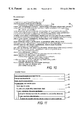
- FIG. 6 shows how three exemplary relationships are modelled at the activity level, in one embodiment of the invention.
- FIG. 7 schematically illustrates constraints between activity states for (a) the after relationship and (b) the concurrent relationship of FIG. 1;
- FIG. 8 shows schematically the steps involved in the validate relationship of FIG. 6 . in sequence, (a) the submission for validation, (b) the response if the result of the activity being validated is accepted, and (c) if it is rejected;
- FIG. 9 is a schematic illustration of the model of an exemplary process (making a technical report available) employed in accordance with the invention.
- FIG. 10 shows a process description file containing the textual language corresponding to the graphical model of FIG. 9;
- FIG. 11 illustrates diagrammatically the algorithm used to decompose the relationship descriptions into constraints between states of activities
- FIG. 12 shows schematically the system structure and information flow to support delegation of decision making in one embodiment of the invention
- FIG. 13 schematically illustrates an example of how actual state values in an initial activity may be used to determine whether the interactor asks a user for a decision about breaking a constraint:
- FIG. 14 is flow diagram showing the process, in accordance with one embodiment of the invention, by which decisions are made about whether a proposed activity should be carried out:
- FIG. 15 shows a set of user and system states for an activity in one embodiment of the invention, showing the modelling of the assignment of a user state for each of a plurality of users;
- FIG. 16 illustrates the algorithm for implementing the process instantiation (FIG. 11 ), modified to take account of multiple users associated with each activity, in accordance with the embodiment of FIG. 15;
- FIG. 17 is a flow diagram of the “Update” routine (FIG. 5 ( c )) employed, modified to take account of multiple users associated with each activity, in accordance with the embodiment of FIGS. 15 and 16;
- FIG. 18 diagrammatically depicts the representation of activities by system state and a plurality of user micro participations, reflecting state changes in a chronological sequence through history, in another embodiment of the invention
- FIG. 19 is a flow chart of the algorithms for implementing the embodiment of FIG. 18 .
- the present invention may be implemented by means of a suitably programmed conventional computer (or a plurality of such computers networked in a manner well known in the art), such as, for example, a minicomputer running UNIX, or a PC running Windows®.
- a network document processing system for implementing the techniques described herein, is designated by the reference numeral 100 .
- This system is described in more detail in commonly assigned U.S. Pat. No. 5,790,119 issued Aug. 4, 1998 and which is incorporated by reference herein.
- the network 100 can be implemented using a variety of hardware platforms and includes devices for input including scanner or digital copier 102 , keyboard 104 , pointing device or mouse 106 , microphone 108 , and video camera 110 .
- the system further has devices for output including display terminal 112 , printer 114 , and speakers 116 .
- Input/output (I/O) devices include facsimile 120 , file server 122 , and telephone 124 .
- Server 122 is configured central to or remote from workstation 82 with public, shared and/or private data storage that is differentiated by user access rights.
- the server 122 includes relational database system 126 , network administration system 12 B, mail system 130 (e.g. email, voice mail) and data storage and retrieval system 132 , and can be physically configured using optical drives, hard drives, floppy drives and/or tape drives.
- the relational database system 126 provides systems with fast query and retrieval of data.
- Workstation 82 operates in a collaborative environment, where users at different workstations 82 can work together in real time to process and distribute public, shared or private information existing in different forms.
- Public data is defined herein as data accessible by anyone, shared data is defined as data accessible by a limited number of users and private data is data uniquely accessible by a single user.
- Workstation 82 can exist in a distributed or centralised environment. In either environment, workstation 82 is connected to other systems and devices through local area network (LAN) or wide area network (WAN) 134 , gateway 136 . and/or modem 138 .
- LAN local area network
- WAN wide area network
- gateway 136 gateway 136
- modem 138 a number of workstations extend distributed processing and storage capabilities to each other, by providing for example redundant storage or a single mounting of a unique application.
- any of the multiple workstations 82 on the network may comprise a computer having a standard microcomputer (PC) architecture, which is well known in the art.
- PC microcomputer
- Workstation 82 includes an object oriented user interface (Ul) 142 that uses icons and windows to represent various data objects and user applications such as a display illustrating an office desktop metaphor employing various abstractions of a typical office environment.
- User interfaces using windows and icons having an object oriented methodology to present metaphors for maintaining data, navigating through various user spaces and presenting abstract computer concepts are well known, an example of which is Globalview TM (“GV”) software available from Xerox Corporation, which uses abstractions such as a desktop, inbasket, outbasket and documents.
- GV Globalview TM
- the Ul 142 can operate remotely from any system; it is extensible across network services using remote windowing protocols such as X windows (“X Window System”, W. Scheifler and James Gettys, Digital Equipment Corporation, U.S., 1992, ISBN 1-55558-088-2).
- the Ul on printer 114 is available remotely from any workstation 82 or alternate service such as scanner 102 .
- this shows a representation 2 of an activity in one embodiment of the invention, showing a set of user and system states.
- the activity may be, for example, creating or adding a contribution to a document, making an amendment to a document (or any of the functionalities conventionally provided by available word-processing, spreadsheet, database or other application software), applying some form of authentication to a document (e.g. approving, signing off), or the like.
- an activity is represented with six possible states—three user states 4 and three system states 6 .
- the user states 4 represent how the user is currently interacting with the activity, and are defined as follows.
- Inactive means that no user is carrying out the activity.
- Active means that a user is working on the activity.
- Ready means that a user has declared an activity completed.
- the system states 6 represent the states the system believes the activity(ies) to be in, based on resolving the constraints which define the dependencies across activities.
- the system states 6 are defined as follows.
- Disabled means that there are still conditions to be met before the activity can be started according to the underlying model of the process.
- Enabled means that all conditions have been met to allow the activity to be started.
- Pending means that all conditions have been met to allow the activity to be finished.
- the user states 4 and system states 6 are independent and an activity is always in one user state and one system state.
- the effect is similar to the three state model of the traditional approach described earlier, in other words, the activities are carried out precisely in accordance with the sequence defined in the process model.
- the technique described here has two properties which allow greatly increased flexibility in the ordering of activities.
- the representation of the user states 4 allows for system states 6 to be over-ridden, but ensures that the system has a complete record of what is going on.
- a user may have information to hand to carry out an activity even though it is still disabled because information required by prior activities has not yet been entered into the system.
- the traditional approach would require the user to wait until the system was brought up to date, but the technique of this invention allows it to be entered when convenient. (In this situation, an appropriate warning can be given to make sure the user realises the potential mismatch and its implications.)
- the enabled state allows the system to represent a situation where conditions exist for an activity to be started, but not for it to be completed.
- a common example of this in knowledge intensive activities is where information has to be gathered from a number of sources. It may be useful to begin carrying out activities such as summarising or collating this information before it is all available; The traditional approach would not allow this to be represented.
- FIG. 3 this schematically illustrates the relationship between two activities A and B in one embodiment of the invention. Through one example, it is illustrated how the required state dynamics are achieved by the propagation of constraints.
- FIG. 3 represents the relationship between activities A and B, with each arrowed line 8 , 10 representing a constraint.
- the simple “after” relationship i.e. B can only be performed after A is completed
- this relationship (“B after A”) is represented by two constraints, corresponding to arrows 8 , 10 emanating from the enabled system state 12 of activity B.
- the required behaviour is for B to be unable to reach the enabled state 12 (and therefore must stay at the disabled state) until activity A is both ready and pending.
- enabled of B is constrained by both ready and pending of A.
- a constraint is said to be satisfied when the constraining state has been reached.
- the general rule is that a constrained state can only be reached when all of its constraints have been satisfied.
- each activity is created with the above mentioned intra-activity constraints explicitly in place.
- the constraints which constitute the relationship type are added to the appropriate states. Every state has two lists of references to other states. One is the list of the states that this state constrains, and the other is the list of states that constrain this one. Updating these lists is the action of adding a constraint.
- the constraint propagation ignores the relationships themselves, working purely at the level of the constraints they caused to be added. Whenever an activity changes state, all of the states involved in the change inform each of the states they constrain. Whenever a state is informed of a change in any one of its constraining states, it polls all of its constraining states to determine whether it can now be reached. If there is any change in its status, it dutifully informs all of its constrainees.
- FIG. 5 is a schematic flow diagram of the algorithm performing state changes in accordance with the invention.
- the unconventional use of names associated with portions of the flowchart attempts to allow the diagram to represent the mutually recursive calls between “Update” and “Changed”.
- calls to a named flowchart portion “of” a state mean that the state is referred to as “this” state within the execution of that portion of the flowchart.
- step s 2 a request for a change of user state is awaited.
- the mechanism is invoked by a call to “Change User State” at step s 4 (system states are never changes by means other than constraint propagation).
- step s 6 a call is made to the “Changed” of the previous and new states; i.e., if the user has requested a change from state A.x to A.y, the routine of FIG. 5 ( b ) is performed for each of states A.x and A.y.
- processing returns to step s 2 (FIG. 5 ( a )).
- the routine involves (step s 8 ) calling “Update” of each state constrained by this one; i.e. if B.k and B.l are constrained by A.x, the routine of FIG. 5 ( c ) is performed for each of states B.k and B.l.
- processing returns to step s 6 (FIG. 5 ( a )).
- step s 10 the constraining states for the current state are polled.
- step s 11 the constraining states for the current state are polled.
- step s 11 the constraining states for the current state are polled.
- step s 12 the current status against that desired. If this state is current, the processing returns to step s 8 (FIG. 5 ( b )). If this state is not current, it is made current at step s 13 , and the routine “Changed” (FIG. 5 ( b )) called at step s 14 .
- step s 15 a check is made (step s 15 ) of the current status against that desired. If this state is not current, the processing returns to step s 8 (FIG. 5 ( b )). If the state is current, this state is made no longer current at step s 16 . Then, and the routine “Changed” (FIG. 5 ( b )) called at step s 14 .
- steps s 12 and s 15 are that only when the current status is different to that desired is the appropriate change made and the routine “Changed” called.
- routine of FIG. 5 ( c ) it may be discovered that there is no need to change anything, such as in cases where (a) all constraints are satisfied and the state was already reached, or (b) not all constraints are satisfied and the state is not marked as current.
- this shows three exemplary relationships modelled at the activity level—after, concurrent and validate.
- the activities may be any of those mentioned in section B above.
- FIGS. 7 and 8 illustrate how the relationships of FIG. 6 are implemented in one exemplary form, in terms of constraints between states of the activities, using the activity states described in detail in above.
- FIG. 7 ( a ) this diagrammatically shows the after relationship of FIG. 6 .
- This relationship means that an activity should not normally be started until prior activities are completed. (This is similar to a traditional sequential relationship.)
- the after relationship is defined so that when all the other activities on which an activity depends are done (i.e. ready and pending), then it becomes enabled, which means that as far as the model is concerned, the activity can or should be now be carried out. (In fact, as long as there are no other constraints preventing the pending state being reached, e.g. a validation being required—see below, it will fall immediately through to pending.)
- FIG. 7 ( b ) shows a concurrent relationship of FIG. 6, in accordance with which an activity can be started when activities on which it depends have started, but not necessarily completed.
- the concurrent relationship is defined so that when an activity becomes active and enabled (or pending), then other activities which depend on it also become enabled.
- the validate relationship of FIG. 6 is show in FIG. 8 .
- the validate relationship is a two-way relationship which involves information being passed from one person to another and then typically returned to the original person.
- a typical use of this pattern is in getting the results of an activity signed off, but it may involve modifications of transformations of the original work. (In traditional workflow representations, this kind of pattern is very difficult to represent since, for example, if a piece of work is found to be unsatisfactory it may loop backwards and forwards an arbitrary number of times. Consequently, this may be very clumsy (and difficult) to model.)
- the validate relationship looks like any other relationship at the activity level, the two-way nature of the relationship makes the underlying semantics a little more complicated.
- FIG. 8 ( a ) shows the step in the validate relationship of submitting for validation.
- the system state of an activity to be validated will be held enabled, and when it is deemed ready by the user, the validation activity (normally) becomes pending. This makes it formally available to the person doing the validation.
- One of two possible responses can be returned to the original user—either accepted or rejected. As shown in FIG. 8 ( b ), if it is accepted, when the validator finishes the validation, the original activity becomes pending, and since it was already ready, therefore becomes fully completed.
- the submission may be rejected, in which case the original activity is reset to inactive and disabled.
- the validating activity is also reset so that it will be ready to receive the revised version to be validated (see FIG. 8 ( c )). (Feedback about the reason for rejection may also be passed back to the person asking for validation.) FIG.
- FIG. 9 shows a graphical model of the process used in the exemplified case—preparing and making available a technical report, with activities including obtaining clearance for publication, peer review, copy-editing, assigning a number, and making the technical report available on a page of the World Wide Web which is accessible externally.
- FIG. 10 shows a process description file containing the textual language corresponding to the graphical model of FIG. 9
- the process description file in FIG. 10 defines each activity of the process by giving a name, and specifies its relationships (or “dependencies”) with other activities.
- the process description file comprises a set of activity specifications 51 , 52 , 53 , 54 , . . . etc., one for each activity in the process.
- the activity “copy-edit” has two relationships, one of the type validates with “submit-tech-report”, and the other of type after with “check-peer-review”.
- the first element in the bracketed list after the activity names (“one of ( . . . )”/“any of ( . . . )”/“nobody”) is a means of one or more users to an activity.
- the algorithm of FIG. 11 uses typed, directed relationships (dependencies) between activities.
- the activity-level relationships are resolved into constraints on states of the activities, at the time of instantiation. This means a lot more processing work at that time, but also speeds the processing of state changes. It will be understood that it is quite possible to compute the significance of having a relationship at the time any state of the activity at either end changes, but this would make the system somewhat slower.
- the algorithm operates as follows.
- Step 61 receive request to create new process instance—the algorithm is fired-off. It is useful to consider the Process Engine (discussed further below) as an object that sits around waiting to be asked to do various tasks, process instantiation. being one of them.
- Step 62 parse process description file—read the file shown in FIG. 10, converting the textual content into internal representations of the specification. Parsing techniques are well known in the art. Specifically, the process description file comprises multiple activity specifications; and the process of parsing the file is that of extracting the process-type name (“tech-report”) and the activity specification information.
- Step 63 create object for Process Instance, i.e. create a Process Instance object.
- An object may be defined as some data and some code describing its behaviour. In the case of the process instance object, this maintains state: a mapping from activity names to activity objects, and another from resource names to their current values.
- Step 64 create object for activity, i.e. create an activity object.
- An activity object comprises some data (its name, its state, etc.), and some code that makes it behave like an activity object should, so its state changes appropriately depending on the state of its related activities, and it informs its related activities if its state does change, etc.
- Step 65 associate activity object with process instance object.
- An activity object maintains a record of the process instance it is part of, and a process instance maintains a list of its comprising activity instances. This step is the setting-up of these records.
- Step 66 look up the relationship type to find the constraints (see above) that constitute that relationship.
- Step 67 combine the constraint with those already existing on the source/destination. This step comprises take the activity object currently being set up, and taking the activity object that is intended as the destination of the dependency being constructed, and add a constraint between the states specified, and in the direction specified in the dependency specification.
- a process engine 32 has access to models, stored in memory in a manner well known in the art, of processes based around structured sets of activities. Each activity may be, for example, creating or adding a contribution to a document, making an amendment to a document, applying some form of authentication to a document, or the like.
- an interactor 34 mediates between the process engine 32 and the user 36 .
- the configuration of FIG. 12 is a simplified form—there may be one or more further modules mediating between the process engine 32 and the interactor 34 .
- the current implementation of the invention also includes an interest manager which allows multiple interactors 34 to be used simultaneously and keeps track of what information each is interested in.)
- the interactor 34 is the focus for providing the user with information about available activities as well as being the focus for interacting with them.
- the interactor 34 registers for all changes in process (activity) state which are relevant for the facilities it provides. However. in addition to simply reflecting the current state of activities as represented via the process model, it provides a mechanism for tailoring how the process engine responds to conflicts which result from a requested change of state (for example, if the user requests access to an activity which is not yet formally ready to be acted on; i.e. in the example disclosed in section B above it is not yet in the enabled state). Exemplary states for the activities are discussed in further detail below.
- the interactor 34 automatically refuses to allow any constraints to be broken and the user is not presented with, or is refused permission to begin, an activity which is not ready to be started.
- the interactor 34 passes information to the user about which activities are causing a constraint to be broken and the user decides whether or not to go ahead.
- the first mechanism adds information to the relationships between activities in the process (model) description. There are a number of ways that this can be done. In one exemplary embodiment the relationships are simply specified as “hard” or “soft”. For example, a “hard” relationship may be used for specifying the situation there are physical constraints which make one activity impossible to carry out without another being completed, or may be used to make sure that safety critical issues are not overlooked. A “soft” relationship signifies that it is not generally appropriate to carry out a particular activity out of sequence. but recognises that there may be times when it should be allowed.
- the interactor 34 is responsible for making sure a hard relationship (and the constraint(s) corresponding to it) is not broken, but it passes on a query. to the user 36 about whether it is appropriate to break a soft relationship (and the constraint(s) corresponding to it). It is important to note that these are characteristics of the relationship which are not used directly by the process engine 32 to compute the implications of state changes, but provide information to the interactor 34 to help refine the kinds of choices which are available to the user.
- the dependencies are arrived at on the basis of whether the user or users concerned are “expert” or “novice” (or any predetermined level in-between). That is, information is specified about users with different kinds of skill levels. and it will be appreciated that any number of designation between and including expert and novice may be provided.
- the interactor 34 thus has this information at its disposal for use as a factor in resolving conflicts. It will also be appreciated that a multitude of combinations of hard/soft constraints with expert/novice factors may be employed.
- the second mechanism uses information that can be inferred from the state of the process. If sufficient state information is available, it can be possible to determine that an activity is “definitely not ready” or is “nearly ready”. For example, it is possible to use the mechanism with user and system states as described in section B above.
- this schematically illustrates an example of how actual state values in an initial activity may be used to determine whether the interactor asks a user for a decision about breaking a constraint.
- the second activity is attempted before the first one is ready, the actual state it is in can be used to set conditions for whether or not the user should have the opportunity to break the constraint. As one example, it may be deemed appropriate to allow the user a choice if someone has declared the state active, or perhaps ready, even if it still depends on other activities to be completed. Alternatively, it may be set so that a choice only gets passed on to the user if the system state of the prior activity is enabled, and not if it is disabled. There is no single precise pattern which determines what decisions should be made where.
- FIG. 14 is flow diagram showing the process, in accordance with one embodiment of the invention, by which decisions are made about whether a proposed activity should be carried out.
- the key aspect is that the technique allows the decision to be made at one of three distinct levels (controlled via the interactor 34 ).
- the decision may effectively be made to be in line with the normative process (model) as instantiated in the process engine 32 (i.e. the “normal” way of doing things).
- the instantiation process is described in section C above.
- this normative route may be over-ridden by local contextual information stored in the interactor 34 , or the user 36 may be asked to make the decision.
- An activity may be defined to allow an arbitrary (or maximum) number of participations to be created as requested by relevant users.
- An activity may be defined as complete only when the system state is pending and all user participations signify they are ready.
- An activity may be defined to be complete when the system state is pending and any one user participation is ready.
- An activity may be defined to be complete when the system state is pending and a given number, or some other subset of user participations are ready.
- FIG. 15 shows a set of user and system states for an activity in one embodiment of the invention, showing the modelling of the assignment of a user state for each of a plurality of users.
- States of activities are represented by parallel “user” and “system” states.
- the example shows an activity represented with one set of possible system states and a number of sets of possible user states (for User 1 , User 2 , User 3 . . . Usern) corresponding to different participants involved in the activity.
- there are three possible states for each set although a different number of states is possible.
- Dependencies are defined in terms of constraints between states. When a new set of user states are added, it is necessary to make sure that we also add constraints to them appropriately, according to the dependencies that the activity has.
- Done may not be readily apparent, but consider now that we want to add another set of user states to activity A.
- the states are added, and we wire them in by adding a constraint from Done to Ready.
- the result is that Done is constrained by Pending on the system side, and all of the Readys on the user side. It was unnecessary to consult the record of relationships and manipulate related activities—those other activities all refer to Done, and the constraints on Done have been updated. Having Done as a common point of reference means it is unnecessary to do us much processing when we add or remove a set of user states, and also when we add or remove dependencies with other activities. On the other hand, it does mean another state per activity to deal with, but this is the currently preferred implementation of multiple sets of user states.
- processing may be amended by adding an extra step in the process instantiation algorithm, which is expressed in the diagram of FIG. 11 .
- FIG. 16 illustrates the algorithm for implementing the process instantiation, but modified to take account of multiple users associated with each activity, in accordance with the embodiment of FIG. 15 .
- the modification consists of inserting steps (designated 68 , 69 ) between the steps of “Associate activity object with a process instance object” and “For each relationship in the activity specification”.
- the steps inserted comprise, for each required participation (user participant), “Create participation” (step 68 ), wherein a new state set, i.e. comprising three user states, is created corresponding to this participant, and “Associate participation with activity object” (step 69 ).
- Steps 68 , 69 are required if participations (sets of user states) are known at the time of instantiation. This would be the case if the activity descriptions contained this information and the parser were coded so as to extract it.
- the modified algorithm comprises examining the internal representation of the activity specification and executing steps 68 , 69 once, for each required participation, the additional steps comprising:
- Step 68 create participation, i.e. create a participation (set of user states) object.
- Step 69 associate participation with activity object, i.e. in the activity object, add the participation object to its list of associated participation objects. For the participation object, identify the activity object as being the activity object to which it belongs.
- FIG. 17 is a flow diagram of the “Update” routine employed in accordance with the embodiment of FIG. 15, modified to take account of multiple users associated with each activity.
- the algorithrm for performing state changes in accordance with the invention is the same as in FIG. 5, except that in the routine of FIG. 5 ( c ), step 11 is modified to check whether the state should be current.
- the principle used so far may be characterised as exclusively employing the universal quantifier in determining whether a constrained state can be considered current (i.e., “for all” constraining states, that constraining state is current). Some generality can be attained by permitting the use of the existential quantifier (i.e., “there exists” a constraining state that is current). This allows us to say that a state is reached when any one or more of its set of constraining states becomes current, which provides the basis for an after-one dependency type.
- More expressiveness is required if it is desired to say that an activity is defined to be complete when the system state is pending and a given number , or some other subset of user participations are ready. Firstly, it is necessary to be able to express that a state is reached when a certain number (other than 1 or all) of its constraining states are current, e.g. using a greater-than operator, as is well-known to those skilled in the art. Secondly, it is necessary to be able to combine the kinds of expressions we have identified so far, into compound expressions. In particular, it is necessary be able to say “the system state is pending AND a given number . . . are ready”. The logical operator AND, and the other operators of Boolean algebra, which are well known to those skilled in the art, may be used to generalise the expressiveness of the relations employed.
- the participation is used to flag, and potentially give access to, contact people who are responsible for processes which produce input on which the current activity relies, or who will take the output from the current process.
- the possible states are used to allow for, mark and give feedback on work being done on these related processes without the person (people) responsible for the current process having to have access to the details of these related processes.
- the “giving input” participation can mark rework being done on an input process.
- sections B to D above do not have any mechanism for tracking the history of interaction with an activity.
- the embodiment described in this section extends the techniques already described by representing a number of parallel “micro-participations” for each user involved in an activity. This allows the history of interaction to be recorded, for example, to support any necessary rework or to support. reflection on the process.
- FIG. 18 diagrammatically depicts the representation of activities by system state and a plurality of user micro-participations, reflecting state changes in a chronological sequence through history, in another embodiment of the invention.
- states of activities are represented by a “system” state and a series of “user micro-participations” which reflect the state changes through which the history of user interaction with the particular activity has gone.
- the example of FIG. 18 shows an activity represented with one set of system states and a number of these micro-participations. In this example (and the current implementation) there are three possible states for each set, although different states are possible.
- the system states are the same as described previously.
- the set of micro-participation states represent the state of a user's interaction with the system over time. For each micro-participation:
- Inactive means that no user is currently working on the activity
- Active means that the activity is currently being worked on by a user
- the system state is independent from the micro-participations.
- the interaction history micro-participations build up over time. Each time the user state changes, the previous state is preserved, and a new micro-participation is added. There are at least four ways in which this can be used:
- the micro-participation also acts as a focus around which additional information about what happened while the activity was in the state recorded. This can include the duration of the state, and what resources such as documents or other people were involved. In this way, for example, the documents used to support a particular revision of a piece of a piece of work can be identified later, perhaps if it has to be further re-worked.
- an activity is fully completed when it is both ready and pending—i.e. the system state and the most recent micro-participation are aligned and do not depend on any other uncompleted activities.
- it also allows it to be re-opened if a new micro-participation is created which is inactive (e.g. as a result of a validation failure) or ready (e.g. because re-work is being carried out.
- FIG. 19 is a flow chart of the algorithms for implementing the embodiment represented in FIG. 18 . This algorithm is the same as FIG. 5, except as described below.
- step 4 is replaced by steps s 41 to s 44 .
- step s 41 once a request for change in user state has been received, the current micro-participation (state condition) is added to the history list—a list of predetermined length giving a condition (state) of-each of the micro-participations up to and including the previous one in chronological order. (It will be appreciated that when it comes to resolving constraints (discussed elsewhere), it the current micro-participation which is used in the constraint resolving routine.)
- step s 42 a micro-participation is created with a new state. Then, the new micro-participation created in step s 41 is associated (step s 43 ) with a timestamp (e.g., including date, time). At the subsequent step s 44 the new micro-participation is made the current one, and the processing proceeds to step s 6 and continues as described in section B above.
- a timestamp e.g., including date, time
- micro-participations could be used for each user participation.
Abstract
Description
Claims (18)
Applications Claiming Priority (9)
| Application Number | Priority Date | Filing Date | Title |
|---|---|---|---|
| GBGB9526429.7A GB9526429D0 (en) | 1995-12-22 | 1995-12-22 | Process support using typed dependecies |
| GB9526428 | 1995-12-22 | ||
| GBGB9526428.9A GB9526428D0 (en) | 1995-12-22 | 1995-12-22 | Process support with conflict resolution |
| GBGB9526430.5A GB9526430D0 (en) | 1995-12-22 | 1995-12-22 | Process support system using system and user states |
| GB9526430 | 1995-12-22 | ||
| GB9526429 | 1995-12-22 | ||
| GBGB9623899.3A GB9623899D0 (en) | 1995-12-22 | 1996-11-18 | Process support using multiple user state sets |
| GB9623899 | 1996-11-18 | ||
| PCT/GB1996/003229 WO1997023837A2 (en) | 1995-12-22 | 1996-12-23 | Process support using system and user states |
Publications (1)
| Publication Number | Publication Date |
|---|---|
| US6421700B1 true US6421700B1 (en) | 2002-07-16 |
Family
ID=27451374
Family Applications (1)
| Application Number | Title | Priority Date | Filing Date |
|---|---|---|---|
| US09/091,366 Expired - Lifetime US6421700B1 (en) | 1995-12-22 | 1996-12-23 | Method and system for work process support using independent system and user states |
Country Status (4)
| Country | Link |
|---|---|
| US (1) | US6421700B1 (en) |
| EP (1) | EP0868701A2 (en) |
| JP (1) | JP2001501752A (en) |
| WO (1) | WO1997023837A2 (en) |
Cited By (35)
| Publication number | Priority date | Publication date | Assignee | Title |
|---|---|---|---|---|
| US20020019838A1 (en) * | 2000-07-05 | 2002-02-14 | Silanis Technology Inc. | Status identifier for identifying the approval status of an electronic document |
| US20020080155A1 (en) * | 1998-12-18 | 2002-06-27 | Abbott Kenneth H. | Supplying notifications related to supply and consumption of user context data |
| US6600499B1 (en) * | 2000-04-13 | 2003-07-29 | International Business Machines Corp. | Method and system for displaying status of critical indicators on diverse display devices and indicating changes in status |
| US20030154121A1 (en) * | 1996-04-10 | 2003-08-14 | Paul M. Konnersman | Computer-based system for work processes that consist of interdependent decisions involving one or more participants |
| US6636243B1 (en) * | 2000-04-13 | 2003-10-21 | International Business Machines Corp. | Method and system for displaying status of critical indicators on diverse display devices and indicating a history of status changes |
| US6661434B1 (en) * | 2000-04-13 | 2003-12-09 | International Business Machines Corporation | Method and system for displaying status of critical indicators on diverse display devices |
| US20040133588A1 (en) * | 2002-12-19 | 2004-07-08 | Rick Kiessig | Graphical user interface for system and method for managing content |
| US20060074737A1 (en) * | 2004-10-01 | 2006-04-06 | Microsoft Corporation | Interactive composition of workflow activities |
| US20060074704A1 (en) * | 2004-10-01 | 2006-04-06 | Microsoft Corporation | Framework to model cross-cutting behavioral concerns in the workflow domain |
| US20060074730A1 (en) * | 2004-10-01 | 2006-04-06 | Microsoft Corporation | Extensible framework for designing workflows |
| US20060074731A1 (en) * | 2004-10-01 | 2006-04-06 | Microsoft Corporation | Unified model for authoring and executing flow-based and constraint-based workflows |
| US20060095469A1 (en) * | 2004-11-01 | 2006-05-04 | Willy Jeffrey H | System and method for facilitating peer review of a deliverable |
| US20070043459A1 (en) * | 1999-12-15 | 2007-02-22 | Tangis Corporation | Storing and recalling information to augment human memories |
| US20070168502A1 (en) * | 2000-04-02 | 2007-07-19 | Tangis Corporation | Dynamically exchanging computer user's context |
| US20070239498A1 (en) * | 2006-03-30 | 2007-10-11 | Microsoft Corporation | Framework for modeling cancellation for process-centric programs |
| US20070239505A1 (en) * | 2006-03-30 | 2007-10-11 | Microsoft Corporation | Abstract execution model for a continuation-based meta-runtime |
| US20070266318A1 (en) * | 1998-12-18 | 2007-11-15 | Abbott Kenneth H | Managing interactions between computer users' context models |
| US20080010082A1 (en) * | 2006-06-27 | 2008-01-10 | International Business Machines Corporation | System and method for business process management |
| US20090216783A1 (en) * | 2008-02-25 | 2009-08-27 | Alexander Gebhart | Hierarchical system operation in an adaptive computing environment |
| US7590934B2 (en) * | 1999-09-24 | 2009-09-15 | Xerox Corporation | Meta-document and method of managing |
| US7689919B2 (en) | 1998-12-18 | 2010-03-30 | Microsoft Corporation | Requesting computer user's context data |
| US7734780B2 (en) | 1998-12-18 | 2010-06-08 | Microsoft Corporation | Automated response to computer users context |
| US20100153345A1 (en) * | 2008-12-12 | 2010-06-17 | Thilo-Alexander Ginkel | Cluster-Based Business Process Management Through Eager Displacement And On-Demand Recovery |
| US20100169863A1 (en) * | 2008-09-26 | 2010-07-01 | Bluetie, Inc. | Methods for determining resource dependency and systems thereof |
| US7779015B2 (en) | 1998-12-18 | 2010-08-17 | Microsoft Corporation | Logging and analyzing context attributes |
| US7877686B2 (en) | 2000-10-16 | 2011-01-25 | Microsoft Corporation | Dynamically displaying current status of tasks |
| US7945859B2 (en) | 1998-12-18 | 2011-05-17 | Microsoft Corporation | Interface for exchanging context data |
| US8020104B2 (en) | 1998-12-18 | 2011-09-13 | Microsoft Corporation | Contextual responses based on automated learning techniques |
| US8103665B2 (en) | 2000-04-02 | 2012-01-24 | Microsoft Corporation | Soliciting information based on a computer user's context |
| US8181113B2 (en) | 1998-12-18 | 2012-05-15 | Microsoft Corporation | Mediating conflicts in computer users context data |
| US8225214B2 (en) | 1998-12-18 | 2012-07-17 | Microsoft Corporation | Supplying enhanced computer user's context data |
| US20120278903A1 (en) * | 2011-04-30 | 2012-11-01 | Vmware, Inc. | Dynamic management of groups for entitlement and provisioning of computer resources |
| US8346724B2 (en) | 2000-04-02 | 2013-01-01 | Microsoft Corporation | Generating and supplying user context data |
| US9183306B2 (en) | 1998-12-18 | 2015-11-10 | Microsoft Technology Licensing, Llc | Automated selection of appropriate information based on a computer user's context |
| WO2017131609A1 (en) * | 2016-01-25 | 2017-08-03 | Entit Software Llc | Coordinating operation of a number of different modules |
Families Citing this family (1)
| Publication number | Priority date | Publication date | Assignee | Title |
|---|---|---|---|---|
| US6973652B1 (en) | 1999-12-06 | 2005-12-06 | International Business Machines Corporation | Sequencing of tasks within customer service processing systems |
Citations (3)
| Publication number | Priority date | Publication date | Assignee | Title |
|---|---|---|---|---|
| US5301320A (en) | 1991-06-28 | 1994-04-05 | Digital Equipment Corporation | Workflow management and control system |
| EP0592072A2 (en) | 1992-10-07 | 1994-04-13 | International Business Machines Corporation | Computerized process control system |
| EP0335638B1 (en) | 1988-03-28 | 1996-09-18 | Digital Equipment Corporation | System for facilitating coordination of activities by a plurality of actors |
-
1996
- 1996-12-23 US US09/091,366 patent/US6421700B1/en not_active Expired - Lifetime
- 1996-12-23 JP JP09523436A patent/JP2001501752A/en not_active Ceased
- 1996-12-23 WO PCT/GB1996/003229 patent/WO1997023837A2/en not_active Application Discontinuation
- 1996-12-23 EP EP96945163A patent/EP0868701A2/en not_active Withdrawn
Patent Citations (3)
| Publication number | Priority date | Publication date | Assignee | Title |
|---|---|---|---|---|
| EP0335638B1 (en) | 1988-03-28 | 1996-09-18 | Digital Equipment Corporation | System for facilitating coordination of activities by a plurality of actors |
| US5301320A (en) | 1991-06-28 | 1994-04-05 | Digital Equipment Corporation | Workflow management and control system |
| EP0592072A2 (en) | 1992-10-07 | 1994-04-13 | International Business Machines Corporation | Computerized process control system |
Non-Patent Citations (1)
| Title |
|---|
| Baumann, L.S. et al., "Automated workflow control: a key to office productivity", AFIPS Conference Proceeedings, 1980 National Computer Conference, Anaheim, CA, May 19-22, pp. 549-554, XP002030336. |
Cited By (75)
| Publication number | Priority date | Publication date | Assignee | Title |
|---|---|---|---|---|
| US20030154121A1 (en) * | 1996-04-10 | 2003-08-14 | Paul M. Konnersman | Computer-based system for work processes that consist of interdependent decisions involving one or more participants |
| US6877153B2 (en) * | 1996-04-10 | 2005-04-05 | Paul M. Konnersman | Computer-based system for work processes that consist of interdependent decisions involving one or more participants |
| US9372555B2 (en) | 1998-12-18 | 2016-06-21 | Microsoft Technology Licensing, Llc | Managing interactions between computer users' context models |
| US7689919B2 (en) | 1998-12-18 | 2010-03-30 | Microsoft Corporation | Requesting computer user's context data |
| US20020080155A1 (en) * | 1998-12-18 | 2002-06-27 | Abbott Kenneth H. | Supplying notifications related to supply and consumption of user context data |
| US9559917B2 (en) | 1998-12-18 | 2017-01-31 | Microsoft Technology Licensing, Llc | Supplying notifications related to supply and consumption of user context data |
| US20070266318A1 (en) * | 1998-12-18 | 2007-11-15 | Abbott Kenneth H | Managing interactions between computer users' context models |
| US9183306B2 (en) | 1998-12-18 | 2015-11-10 | Microsoft Technology Licensing, Llc | Automated selection of appropriate information based on a computer user's context |
| US8677248B2 (en) | 1998-12-18 | 2014-03-18 | Microsoft Corporation | Requesting computer user's context data |
| US8626712B2 (en) | 1998-12-18 | 2014-01-07 | Microsoft Corporation | Logging and analyzing computer user's context data |
| US8489997B2 (en) | 1998-12-18 | 2013-07-16 | Microsoft Corporation | Supplying notifications related to supply and consumption of user context data |
| US8181113B2 (en) | 1998-12-18 | 2012-05-15 | Microsoft Corporation | Mediating conflicts in computer users context data |
| US20020080156A1 (en) * | 1998-12-18 | 2002-06-27 | Abbott Kenneth H. | Supplying notifications related to supply and consumption of user context data |
| US9906474B2 (en) | 1998-12-18 | 2018-02-27 | Microsoft Technology Licensing, Llc | Automated selection of appropriate information based on a computer user's context |
| US6791580B1 (en) * | 1998-12-18 | 2004-09-14 | Tangis Corporation | Supplying notifications related to supply and consumption of user context data |
| US8126979B2 (en) | 1998-12-18 | 2012-02-28 | Microsoft Corporation | Automated response to computer users context |
| US8020104B2 (en) | 1998-12-18 | 2011-09-13 | Microsoft Corporation | Contextual responses based on automated learning techniques |
| US7945859B2 (en) | 1998-12-18 | 2011-05-17 | Microsoft Corporation | Interface for exchanging context data |
| US7062715B2 (en) | 1998-12-18 | 2006-06-13 | Tangis Corporation | Supplying notifications related to supply and consumption of user context data |
| US7779015B2 (en) | 1998-12-18 | 2010-08-17 | Microsoft Corporation | Logging and analyzing context attributes |
| US7203906B2 (en) | 1998-12-18 | 2007-04-10 | Tangis Corporation | Supplying notifications related to supply and consumption of user context data |
| US20070130524A1 (en) * | 1998-12-18 | 2007-06-07 | Tangis Corporation | Supplying notifications related to supply and consumption of user context data |
| US7739607B2 (en) | 1998-12-18 | 2010-06-15 | Microsoft Corporation | Supplying notifications related to supply and consumption of user context data |
| US7734780B2 (en) | 1998-12-18 | 2010-06-08 | Microsoft Corporation | Automated response to computer users context |
| US8225214B2 (en) | 1998-12-18 | 2012-07-17 | Microsoft Corporation | Supplying enhanced computer user's context data |
| US7590934B2 (en) * | 1999-09-24 | 2009-09-15 | Xerox Corporation | Meta-document and method of managing |
| US9443037B2 (en) | 1999-12-15 | 2016-09-13 | Microsoft Technology Licensing, Llc | Storing and recalling information to augment human memories |
| US20070043459A1 (en) * | 1999-12-15 | 2007-02-22 | Tangis Corporation | Storing and recalling information to augment human memories |
| US8103665B2 (en) | 2000-04-02 | 2012-01-24 | Microsoft Corporation | Soliciting information based on a computer user's context |
| US20070168502A1 (en) * | 2000-04-02 | 2007-07-19 | Tangis Corporation | Dynamically exchanging computer user's context |
| US8346724B2 (en) | 2000-04-02 | 2013-01-01 | Microsoft Corporation | Generating and supplying user context data |
| US20080147775A1 (en) * | 2000-04-02 | 2008-06-19 | Microsoft Corporation | Dynamically swapping modules for determing a computer user's context |
| US7647400B2 (en) | 2000-04-02 | 2010-01-12 | Microsoft Corporation | Dynamically exchanging computer user's context |
| US7827281B2 (en) | 2000-04-02 | 2010-11-02 | Microsoft Corporation | Dynamically determining a computer user's context |
| US6600499B1 (en) * | 2000-04-13 | 2003-07-29 | International Business Machines Corp. | Method and system for displaying status of critical indicators on diverse display devices and indicating changes in status |
| US6636243B1 (en) * | 2000-04-13 | 2003-10-21 | International Business Machines Corp. | Method and system for displaying status of critical indicators on diverse display devices and indicating a history of status changes |
| US6661434B1 (en) * | 2000-04-13 | 2003-12-09 | International Business Machines Corporation | Method and system for displaying status of critical indicators on diverse display devices |
| US20020019838A1 (en) * | 2000-07-05 | 2002-02-14 | Silanis Technology Inc. | Status identifier for identifying the approval status of an electronic document |
| US7877686B2 (en) | 2000-10-16 | 2011-01-25 | Microsoft Corporation | Dynamically displaying current status of tasks |
| US20040133545A1 (en) * | 2002-12-19 | 2004-07-08 | Rick Kiessig | System and method for managing content including addressability features |
| US20040133589A1 (en) * | 2002-12-19 | 2004-07-08 | Rick Kiessig | System and method for managing content |
| US20040133588A1 (en) * | 2002-12-19 | 2004-07-08 | Rick Kiessig | Graphical user interface for system and method for managing content |
| US7386532B2 (en) | 2002-12-19 | 2008-06-10 | Mathon Systems, Inc. | System and method for managing versions |
| US20080059495A1 (en) * | 2002-12-19 | 2008-03-06 | Rick Kiessig | Graphical User Interface for System and Method for Managing Content |
| US7386529B2 (en) | 2002-12-19 | 2008-06-10 | Mathon Systems, Inc. | System and method for managing content with event driven actions to facilitate workflow and other features |
| US7386530B2 (en) | 2002-12-19 | 2008-06-10 | Mathon Systems, Inc. | System and method for managing content including addressability features |
| US7386531B2 (en) | 2002-12-19 | 2008-06-10 | Mathon Systems, Inc. | System and method for managing content |
| US20040133544A1 (en) * | 2002-12-19 | 2004-07-08 | Rick Kiessig | System and method for managing content with event driven actions to facilitate workflow and other features |
| US7289973B2 (en) | 2002-12-19 | 2007-10-30 | Mathon Systems, Inc. | Graphical user interface for system and method for managing content |
| US20060074731A1 (en) * | 2004-10-01 | 2006-04-06 | Microsoft Corporation | Unified model for authoring and executing flow-based and constraint-based workflows |
| US8103536B2 (en) * | 2004-10-01 | 2012-01-24 | Microsoft Corporation | Unified model for authoring and executing flow-based and constraint-based workflows |
| US20060074730A1 (en) * | 2004-10-01 | 2006-04-06 | Microsoft Corporation | Extensible framework for designing workflows |
| US20120078677A1 (en) * | 2004-10-01 | 2012-03-29 | Microsoft Corporation | Unified model for authoring and executing flow-based and constraint-based workflows |
| US8170901B2 (en) | 2004-10-01 | 2012-05-01 | Microsoft Corporation | Extensible framework for designing workflows |
| US20060074704A1 (en) * | 2004-10-01 | 2006-04-06 | Microsoft Corporation | Framework to model cross-cutting behavioral concerns in the workflow domain |
| US20060074737A1 (en) * | 2004-10-01 | 2006-04-06 | Microsoft Corporation | Interactive composition of workflow activities |
| US20100306000A1 (en) * | 2004-10-01 | 2010-12-02 | Microsoft Corporation | Unified model for authoring and executing flow-based and constraint-based workflows |
| US7805324B2 (en) * | 2004-10-01 | 2010-09-28 | Microsoft Corporation | Unified model for authoring and executing flow-based and constraint-based workflows |
| US20060095469A1 (en) * | 2004-11-01 | 2006-05-04 | Willy Jeffrey H | System and method for facilitating peer review of a deliverable |
| US20070239498A1 (en) * | 2006-03-30 | 2007-10-11 | Microsoft Corporation | Framework for modeling cancellation for process-centric programs |
| US20070239505A1 (en) * | 2006-03-30 | 2007-10-11 | Microsoft Corporation | Abstract execution model for a continuation-based meta-runtime |
| US20080010082A1 (en) * | 2006-06-27 | 2008-01-10 | International Business Machines Corporation | System and method for business process management |
| US8935371B2 (en) * | 2008-02-25 | 2015-01-13 | Sap Se | Hierarchical system operation in an adaptive computing environment |
| US20090216783A1 (en) * | 2008-02-25 | 2009-08-27 | Alexander Gebhart | Hierarchical system operation in an adaptive computing environment |
| US9477497B2 (en) * | 2008-09-26 | 2016-10-25 | Juniper Networks, Inc. | Methods for determining resource dependency and systems thereof |
| US20100169863A1 (en) * | 2008-09-26 | 2010-07-01 | Bluetie, Inc. | Methods for determining resource dependency and systems thereof |
| US20170083311A1 (en) * | 2008-09-26 | 2017-03-23 | Juniper Networks, Inc. | Methods for determining resource dependency and systems thereof |
| US20100153345A1 (en) * | 2008-12-12 | 2010-06-17 | Thilo-Alexander Ginkel | Cluster-Based Business Process Management Through Eager Displacement And On-Demand Recovery |
| US9588806B2 (en) * | 2008-12-12 | 2017-03-07 | Sap Se | Cluster-based business process management through eager displacement and on-demand recovery |
| US11341158B2 (en) | 2008-12-12 | 2022-05-24 | Sap Se | Cluster-based business process management through eager displacement and on-demand recovery |
| US20120278903A1 (en) * | 2011-04-30 | 2012-11-01 | Vmware, Inc. | Dynamic management of groups for entitlement and provisioning of computer resources |
| US9491116B2 (en) | 2011-04-30 | 2016-11-08 | Vmware, Inc. | Dynamic management of groups for entitlement and provisioning of computer resources |
| US8955151B2 (en) * | 2011-04-30 | 2015-02-10 | Vmware, Inc. | Dynamic management of groups for entitlement and provisioning of computer resources |
| WO2017131609A1 (en) * | 2016-01-25 | 2017-08-03 | Entit Software Llc | Coordinating operation of a number of different modules |
| US10860341B2 (en) | 2016-01-25 | 2020-12-08 | Micro Focus Llc | Coordinating operation of a number of different modules |
Also Published As
| Publication number | Publication date |
|---|---|
| EP0868701A2 (en) | 1998-10-07 |
| WO1997023837A2 (en) | 1997-07-03 |
| WO1997023837A3 (en) | 1997-09-12 |
| JP2001501752A (en) | 2001-02-06 |
Similar Documents
| Publication | Publication Date | Title |
|---|---|---|
| US6421700B1 (en) | Method and system for work process support using independent system and user states | |
| Chomicki et al. | Conflict resolution using logic programming | |
| AU753202B2 (en) | Software system generation | |
| CA2296391C (en) | Visualisation in a modular software system | |
| US6065009A (en) | Events as activities in process models of workflow management systems | |
| Lei et al. | A comparison of workflow metamodels | |
| Casati et al. | Workflow evolution | |
| US6078982A (en) | Pre-locking scheme for allowing consistent and concurrent workflow process execution in a workflow management system | |
| US5530861A (en) | Process enaction and tool integration via a task oriented paradigm | |
| US6529905B1 (en) | Method and system for allowing multiple users to edit a hierarchical data structure | |
| US6263358B1 (en) | Scheduler for a software system having means for allocating tasks | |
| US6820118B1 (en) | Method and system for providing a linkage between systems management systems and applications | |
| US6832201B1 (en) | Method and system for optimizing request shipping in workflow management systems | |
| US20100153160A1 (en) | System for supporting coordination of resources for events in an organization | |
| Chang et al. | Agent-based workflow: TRP support environment (TSE) | |
| Marinescu | Process Coordination and Ubiquitous Computing | |
| US8650568B2 (en) | Method and system for transforming orders for executing them in standard workflow engines | |
| US6507844B1 (en) | Method and system for minimizing network traffic | |
| Reiff-Marganiec et al. | Feature interactions in telecommunications and software systems VIII | |
| EP1577813A1 (en) | Software structure driven approach for implementing workflow | |
| Kim et al. | Practical experiences and requirements on workflow | |
| EP0831406A2 (en) | Implementing a workflow engine in a database management system | |
| Warne | Flexible transaction framework for dependable workflows | |
| Trajcevski et al. | Formalizing and reasoning about the requirements specifications of workflow systems | |
| Jeng | Design coordination modeling: a distributed computer environment for managing design activities |
Legal Events
| Date | Code | Title | Description |
|---|---|---|---|
| AS | Assignment |
Owner name: XEROX CORPORATION, CONNECTICUT Free format text: ASSIGNMENT OF ASSIGNORS INTEREST;ASSIGNORS:HOLMES, JAMES;MACLEAN, ALLAN;ZBYSLAW, ALEX;AND OTHERS;REEL/FRAME:010214/0790;SIGNING DATES FROM 19990803 TO 19990819 |
|
| STCF | Information on status: patent grant |
Free format text: PATENTED CASE |
|
| AS | Assignment |
Owner name: BANK ONE, NA, AS ADMINISTRATIVE AGENT, ILLINOIS Free format text: SECURITY AGREEMENT;ASSIGNOR:XEROX CORPORATION;REEL/FRAME:013111/0001 Effective date: 20020621 Owner name: BANK ONE, NA, AS ADMINISTRATIVE AGENT,ILLINOIS Free format text: SECURITY AGREEMENT;ASSIGNOR:XEROX CORPORATION;REEL/FRAME:013111/0001 Effective date: 20020621 |
|
| AS | Assignment |
Owner name: JPMORGAN CHASE BANK, AS COLLATERAL AGENT, TEXAS Free format text: SECURITY AGREEMENT;ASSIGNOR:XEROX CORPORATION;REEL/FRAME:015134/0476 Effective date: 20030625 Owner name: JPMORGAN CHASE BANK, AS COLLATERAL AGENT,TEXAS Free format text: SECURITY AGREEMENT;ASSIGNOR:XEROX CORPORATION;REEL/FRAME:015134/0476 Effective date: 20030625 |
|
| FPAY | Fee payment |
Year of fee payment: 4 |
|
| FPAY | Fee payment |
Year of fee payment: 8 |
|
| FPAY | Fee payment |
Year of fee payment: 12 |
|
| AS | Assignment |
Owner name: XEROX CORPORATION, NEW YORK Free format text: RELEASE BY SECURED PARTY;ASSIGNOR:BANK ONE, NA;REEL/FRAME:034881/0827 Effective date: 20030625 Owner name: XEROX CORPORATION, NEW YORK Free format text: RELEASE BY SECURED PARTY;ASSIGNOR:JPMORGAN CHASE BANK, N.A.;REEL/FRAME:034882/0471 Effective date: 20061204 |
|
| AS | Assignment |
Owner name: XEROX CORPORATION, CONNECTICUT Free format text: RELEASE BY SECURED PARTY;ASSIGNOR:JPMORGAN CHASE BANK, N.A. AS SUCCESSOR-IN-INTEREST ADMINISTRATIVE AGENT AND COLLATERAL AGENT TO BANK ONE, N.A.;REEL/FRAME:061388/0388 Effective date: 20220822 Owner name: XEROX CORPORATION, CONNECTICUT Free format text: RELEASE BY SECURED PARTY;ASSIGNOR:JPMORGAN CHASE BANK, N.A. AS SUCCESSOR-IN-INTEREST ADMINISTRATIVE AGENT AND COLLATERAL AGENT TO JPMORGAN CHASE BANK;REEL/FRAME:066728/0193 Effective date: 20220822 |