US6397159B1 - Method and system for characterizing terminations in a local area network - Google Patents
Method and system for characterizing terminations in a local area network Download PDFInfo
- Publication number
- US6397159B1 US6397159B1 US09/426,505 US42650599A US6397159B1 US 6397159 B1 US6397159 B1 US 6397159B1 US 42650599 A US42650599 A US 42650599A US 6397159 B1 US6397159 B1 US 6397159B1
- Authority
- US
- United States
- Prior art keywords
- network
- predetermined signal
- response
- cable
- terminator
- Prior art date
- Legal status (The legal status is an assumption and is not a legal conclusion. Google has not performed a legal analysis and makes no representation as to the accuracy of the status listed.)
- Expired - Lifetime
Links
Images


Classifications
-
- H—ELECTRICITY
- H04—ELECTRIC COMMUNICATION TECHNIQUE
- H04L—TRANSMISSION OF DIGITAL INFORMATION, e.g. TELEGRAPHIC COMMUNICATION
- H04L43/00—Arrangements for monitoring or testing data switching networks
- H04L43/50—Testing arrangements
-
- G—PHYSICS
- G01—MEASURING; TESTING
- G01R—MEASURING ELECTRIC VARIABLES; MEASURING MAGNETIC VARIABLES
- G01R31/00—Arrangements for testing electric properties; Arrangements for locating electric faults; Arrangements for electrical testing characterised by what is being tested not provided for elsewhere
- G01R31/08—Locating faults in cables, transmission lines, or networks
- G01R31/11—Locating faults in cables, transmission lines, or networks using pulse reflection methods
-
- H—ELECTRICITY
- H04—ELECTRIC COMMUNICATION TECHNIQUE
- H04Q—SELECTING
- H04Q2201/00—Constructional details of selecting arrangements
- H04Q2201/80—Constructional details of selecting arrangements in specific systems
- H04Q2201/802—Constructional details of selecting arrangements in specific systems in data transmission systems
Definitions
- local area networks comprise a transmission medium and network devices that transmit through it.
- the transmission medium is typically coaxial or twisted-pair wiring.
- the network devices or nodes are the network cards of computer workstations that utilize the network cabling to communicate with each other.
- Dedicated network devices such as hubs, repeaters, bridges, switches, and routers are also used to manage or extend a given LAN or act as inter-networking devices.
- CSMA/CD carrier sense multiple access with collision detection
- Ethernet which is a product of the XEROX Corporation.
- I.E.E.E. has promulgated standards for this protocol; IEEE 802.3 covers 1-persistent CSMA/CD access method and physical layer specification.
- the protocol comes in various implementations, 10Base(2) and (5) are 10 megabit per second (MBPS) networks using different gauges of coaxial cable (2 and 5) in a bus topology. 10Base(T) also operates at 10 MBPS but uses twisted-pair cabling in a star topology in which each node connects to a hub. Newer 100 MBPS implementations such as 100Base(T) are becoming more common with 1 GigaBPS devices in planning and testing.
- MBPS 10 megabit per second
- a number of problems can arise at a LAN's physical layer.
- the electrical conductors may become frayed or broken.
- the shielding may be damaged, failing to protect the conductors from surrounding electromagnetic interference and changing the cable's characteristic impedance.
- the terminators at the end of the network cables in bus topologies or the terminators in the nodes at the ends of the links in star topologies may be poorly matched to the characteristic impedance of the network's cables or non-existent. This produces signal reflections that can impair the operation of the network.
- Another potential problem with a network is the fact that cabling may be too long.
- the IEEE 802.3 10Base(T) protocol limits the cable length to 200 meters with repeaters. This restriction is placed on networks because signals require a non-trivial time to propagate through the entire length of a CSMA/CD network relative to the data rate of the network. Network devices, however, must have some assurance that after they have been transmitting for some minimum time that a collision will not thereafter occur. Additionally, the end of each packet transmission must be allowed to propagate across the entire network before the next transmission may take place. If the cabling is long, the time allocated to this may begin to consume too much of the network's potential bandwidth.
- TDR time domain reflectometry
- TDR has been used to determine the length of the network cable and thus whether it conforms to the relevant protocol. Prior to testing, the network's terminators are removed and the conductors are shorted together or open circuited. The length of the cable may then be determined based on the time delay between when the TDR signal is placed on the network and when the open- or short-circuit reflection is detected at the sending-end.
- the location of a properly configured terminator i.e., a terminator that has been configured to closely match the characteristic impedance of the network cabling, can be remotely detected by analyzing the network's response to a predetermined signal for skin effects.
- the terminator produces a signature that is detectable at the sending-end when predetermined signal, such as a current step function, is injected onto the network cabling.
- predetermined signal such as a current step function
- the magnitude of the voltage at the sending-end will slowly increase. This results from the skin effects and accumulated d.c. resistance across the length of the cable as the step function propagates down its length.
- the voltage After a time corresponding to twice the propagation time between the sending-end and the terminator, the voltage will undergo an inflection. After this inflection, the voltage asymptotically returns to the voltage level initially produced when the step function was generated.
- a network analysis device is connected to the network to inject a predetermined signal, such as the step function, onto the network cabling.
- a predetermined signal such as the step function
- the voltage response of the cabling to this excitation is first digitally sampled and then analyzed in a system controller.
- the system controller reviews the sampled data for the signature of the terminator and then locates it by reference to the delay between when the signal was placed on the cable and the detection of the signature.
- the terminator is detected by determining a change in the influence of skin effects on the response resulting from the step function, which is preferably encased in a packet-like transmission, for example, reaching the terminator.
- the change in skin effects is evidenced by an inflection point in the induced voltage on the network cabling.
- the signature of the terminator is detected by calculating a first-order differential of the response as a function of delay from the generation of the predetermined signal and located where the first order differential indicates an inflection at a highest time delay from the predetermined signal
- the invention features a computer network analysis method.
- the signal responses of communications links of a computer network are detected and terminators identified on the communications links based on the signal responses.
- the acquired information is then displayed, including measures of lengths of the communications links of the computer network.
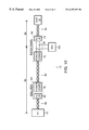
- FIG. 1A is a block diagram showing a network diagnostic device of the present invention
- FIG. 1B is a schematic diagram showing the cross-connect panel supporting physical layer access for the MIU according to the present invention
- FIG. 2 is a timing diagram showing a hybrid packet/step function for detecting terminations on an active network
- FIG. 3 is a state diagram illustrating the operation of the packet/step function generator
- FIG. 4 is a graph of the voltage as function of time when a step function is placed on the network cabling of a LAN;
- FIG. 5 is a process diagram illustrating the data processing performed on the cable's response to the TDR edge to find the terminator
- FIG. 6 is a voltage vs. time plot of an exemplary cable response
- FIG. 7 shows a low pass filtered and first order differential of the exemplary cable's response
- FIG. 8 shows another exemplary cable response illustrating a correction for the real resistance of the cable
- FIG. 9 is an impedance spectrum for the cable response shown in FIG. 8;
- FIG. 10 is another exemplary cable response showing the effect of an LC circuit
- FIG. 11 is an impedance spectrum for the cable response of FIG. 10;
- FIG. 12 is a schematic diagram showing the elements of a network link and the point of attachment of the MIU
- FIG. 13 is a process diagram showing the isolation of the node-side response of the link.
- FIG. 14 is a graphical user interface displaying the information gained from the terminator detection according to the present invention.
- FIG. 1A illustrates a network diagnostic device 50 implementing the present invention.
- Other aspects of the device are described in U.S. pat. appl. Ser. No. 08/619,934, filed on Mar. 18, 1996, entitled Packet Network Monitoring Device, the teachings of which are incorporated herein in their entirety by this reference.
- the illustrated network 5 is configured in a star topology, such as in 10Base(T). It incorporates multiple links 10 - 15 , which operate in a common collision domain, although separate collision domains could exist between the links in other implementations.
- the nodes or computers 16 - 21 are located at the ends of network cables 22 - 27 for each of the links. Each of the nodes includes a terminator 28 - 33 that is matched to the characteristic impedance of the corresponding cables.
- each of the links 10 - 15 is a bus-style network connecting several computers, separate terminator devices are connected at the ends of the network cables 22 - 27 .
- a hub 16 or alternatively switch or other network communications device, enables communications between the nodes by retransmitting packets between the links.
- a media interface unit (MIU) 100 connects a digitizer 120 and signal generation circuits 150 to the physical layer of the network's links 10 - 15 .
- the MIU includes the receiver units R that collectively provide a two-channel input to the digitizer 120 through a summing network 36 .
- the summing network 36 enables individual links to be monitored, or combines the signals of multiple links, on a channel of the digitizer 120 .
- the digitizer should have at least a 500 MHz sampling frequency with eight bits of resolution per sample and a long memory capacity of at least one megabyte of eight bit samples, or preferably 2 to 4 megabytes for 10 MBPS networks. Analysis of 100 MBPS to 1 GBPS networks is facilitated with correspondingly faster sampling frequencies and longer memory capacities.
- FIG. 1B shows one implementation of the MIU 100 integrated into a cross connect panel of the invention.
- Each remote network node 16 - 21 is connected to a wall panel W 1 -W 6 , commonly located in the office 68 in which the computer 20 is located.
- These wall panels receive, in one implementation, four twisted pair wires supporting a communications link in a common jack or connector scheme.
- the wires 70 from the wall panels W 1 -W 6 are bundled into larger horizontal cables 60 of 24 to 48 separate groups of four twisted-pair wires from other nodes in other offices.
- Each of the horizontal cables 14 terminates usually in a wiring closet 72 housing the cross-connect panel 64 and the network communications device 16 .
- Each group of wires of a communications link is associated with and electrically connected to a separate panel-device connector 66 on the front of the cross-connect panel 10 .
- Short jumper cables or patch cords 62 are used between each panel-device connector 66 of the cross-connect panel 64 and the network device 16 .
- cross-connect panels provide a convenient way to terminate the horizontal cables 60 while allowing computers to be connected to different ports of the network communication device 16 .
- the network communications device may be replaced simply by switching the patch cords 24 .
- the panel 64 includes a monitoring port to which the media interface unit (MIU) 100 is connectable.
- the port provides physical layer access to the communications links by supporting direct signal taps to the communications media of the links.
- the digitizer 120 comprises a buffering amplifier 122 a , 122 b on each of the two channels Ch 1 , Ch 2 .
- Two sample-and-hold circuits 124 a, 124 b downstream of each amplifier freeze the detected voltage in each channel for digitization by two analog-to-digital converters 126 a , 126 b .
- the digital outputs of the converters are written into two long memories 128 a, 128 b, one assigned to each channel Ch 1 , Ch 2 .
- the memories 128 a , 128 b function as first-in, first-out (FIFO) buffers that continuously receive and store the output from converters 126 a , 126 b until a trigger signal is received.
- FIFO first-in, first-out
- a system processor 140 is connected to read the arrays of data from the long memories 128 a , 128 b of the digitizer 120 .
- it is a personal computer/workstation, which is also connected to the network 5 via a conventional network card.
- the system processor 140 performs signal processing on the data arrays.
- the system processor 140 also provides the overall control of the device 50 .
- a packet/step function signal generator 150 also under the control of the system processor 140 , is connected to the network 5 via drive circuits D.
- the signal generator 150 has much of the control logic that would be contained in a network card for the relevant network. It can determine when other nodes are transmitting, determine incidences of collisions, and assess when a packet transmission can be made in accordance with the network's protocol.
- the signal generator 150 produces a hybrid step/packet transmission in order to allow the device 50 to perform terminator and physical layer analysis while the network 5 is operational.
- Nodes 16 - 21 can behave unpredictably if a lone step function is transmitted over an idle network. The nodes, however, will generally ignore a packet transmission as long as it is not addressed to the nodes. To utilize this behavior, the signal generator 150 is configured to generate a broadcast diagnostic packet. Packets with this source and destination address will be universally ignored by the network's nodes.
- the step function is inserted where a data payload would typically be found. This renders step function transparent to the nodes.
- FIG. 2 schematically shows the hybrid step/packet transmission 200 for a 10Base(T) CSMA/CD network.
- the packet 200 has a standard length preamble 210 .
- the source and destination addresses 220 , 230 conform to a diagnostic broadcast packet.
- a data payload 240 is started, but then after a predetermined time, the voltage on the cabling is held at a quiescent level, i.e. 0 Volts in most networks, for time t 1 . This period corresponds to the time that is required for a signal to traverse the entire network, usually between 1 and 6 microseconds. This delay allows any echoes to die out.
- the edge 250 of the current step function 252 is generated by producing a predetermined amount of current on the network cabling. This raises the magnitude of the voltage on the cabling to a selected level, e.g. 0.5-5 Volts. As shown, this voltage is preferably close to the normal voltage swings experienced during data transmission, but a stronger signal-to-noise ratio can be obtained by using higher voltages. In either case, the voltage swing should not be so large as to create the risk of damage to any of the node's network cards.
- the step function 252 is maintained for a time that is long enough to allow the edge to propagate throughout the network and the response received back by the digitizer at the sending-end at time t 2 . At the expiration of this time, the voltage on the network is brought back to a quiescent state allowing the other nodes on the network to recognize the end of the transmission.
- the digitizer 120 is used to detect the response of the network 10 to the step function.
- a trigger device 130 of the digitizer is armed by the system processor 140 and triggered by the packet/step generator 150 in response to the transmission of the hybrid packet on the network.
- the system processor then extracts any detectable echo from the sampled event. By analyzing the echo, the location of network termination is determined.
- FIG. 3 is a state diagram for the packet/step function generator 150 .
- the generator is activated by a transmit command that is received from the system controller 140 in step 290 . It then prepares to send the packet in step 291 . First, it waits until the network is idle in step 292 . When there are no transmissions on the network cabling, an external trigger is sent to the trigger device 130 of the digitizer 120 in step 293 and the packet 200 is transmitted on the network in step 294 . The generator then waits until the packet transmission is finished in step 295 . This transmission includes the broadcast source and destination address 230 , 220 , the start of the payload 240 , and the “silent” time t 1 to allow echoes to die out. The edge 250 is then sent in step 296 . It again waits for the conclusion after time t 2 and then signals the system controller 140 in steps 297 and 298 .
- FIG. 4 shows an exemplary network response to the current step function 252 at the sending-end. For clarity, only the portion of sampled signal that resulted from to the step function is shown.
- the response of the network to the step function 252 exhibits two slopes.
- the first slope 410 is indicative of the accumulated DC resistance and skin effects of the cable as the edge 250 propagates towards the terminations 28 - 33 .
- the magnitude of the voltage slowly increases from its initial level v 1 just after the edge 250 .
- the network response exhibits an inflection point 412 where the voltage begins to drift back to its initial level v 1 with a new slope 414 .
- the system processor 140 processes this data from the digitizer 120 and locates the inflection point 412 and determines time T a . Then, by reference to the signal propagation speeds across the network cabling 22 - 27 the processor 140 calculates the distance to the terminators 28 - 33 .
- FIG. 5 illustrates the signal processing performed by the system processor 140 .
- the first step in the signal processing is to isolate the cable's response to the TDR edge in step 510 .
- the data acquisition is triggered in response to the beginning of the hybrid/TDR packet shown in FIG. 2 .
- the only relevant portion of the sampled signal event is the cable's response to the TDR edge 250 .
- FIG. 4 shows an isolated cable response. This response is exceptionally clean, without distortion, example where the terminator inflection point 412 is very evident.
- FIG. 6 Possibly a more common cable response, or worse case situation, is shown in FIG. 6 .
- This cable response shows a number of changes in the cable's characteristic impedance 610 at various time delays from the TDR edge 250 . These could be caused by cable splices, different types of cable, or damage to the cable shielding, for example.
- the data that corresponds to the cable's response is then low pass filtered in step 520 .
- This filtering smooths any high frequency spikes in the cable's response to facilitate the analysis of the trends in the data.
- the response labelled 710 in FIG. 7 shows the low pass filtered response of the cable response shown in FIG. 6 . Many of the spikes 610 are removed in the low pass filtered response 710 of FIG. 7 .
- the filtered data is then compared to short and open circuit thresholds in step 522 of FIG. 5 . If the end of the circuit is not properly terminated in the characteristic impedance, but is an open circuit, the cable's response will be characterized by an increase in the voltage at a delay that corresponds to the distance to the open circuit.
- the inductance associated with the cable length causes the detected response to increase to twice the voltage of the initial TDR edge 250 in the case of a complete open circuit.
- An appropriate open-circuit threshold is 190% of the voltage of the TDR edge. This threshold is applied to the cable's response to determine whether an open circuit exists and the distance to the open circuit represented by the time delay at which the threshold is exceeded.
- a short circuit at the end of the cable will be characterized by drop in the magnitude of the voltage on the cable. This corresponds to the dissipation of the energy of the TDR edge 250 to ground as the step function reaches the short-circuit.
- An appropriate short-circuit threshold is 10% of the voltage of the step function's magnitude. This threshold is similarly applied to the cable's response in step 522 .
- the distance to the short or open circuit corresponds to one-half the delay until either of thresholds are exceeded in the cable's response in step 526 .
- a first-order differential is performed on the cable's response to the TDR edge 250 in step 528 .
- the result of this processing is a plot showing how the cable's response is changing as a function of the delay from the TDR edge.
- the first order differential of the low-pass filtered response 710 is identified as 712 also in FIG. 7 .
- the terminator is then located by finding the highest time delay at which the first order differential becomes positive and remains positive in step 530 .
- This analysis is conceptionalized by beginning at the right side of the first-order differential plot 712 in FIG. 7, and then scanning leftward until the zero-crossing is found (see reference 714 ). This corresponds to the inflection point 412 described in connection with FIG. 4, and the time delay between the zero-crossing 714 and the TDR edge 250 corresponds to twice the distance to the terminator or node at the end of the cable.
- the physical distance is calculated by multiplying the time delay by the propagation speed of the signals over the cable and dividing by two.
- a resistance correction must be performed in factor out the contribution of the real portion of the cable's resistance to the response in step 532 . Since the real resistance has no frequency dependence, by definition, it will not distort any signals transmitted on the line other than causing attenuation.
- FIG. 8 shows an exemplary cable impedance as a function of time delay.
- Plot 810 is the total, real and imaginary, impedance as a function of time delay.
- Plot 812 represents the response that is dictated by only the imaginary portion, i.e., reactance, of the cable's impedance.
- An impedance frequency spectrum shown in FIG. 9 is then generated by normalization and by performing a fast Fourier transform (FFT) on the impedance response 812 .
- FFT fast Fourier transform
- the cable response shown in FIG. 10 could occur in the case of a LC circuit that creates the ringing effect shown by the brief sinusoidal pulse 1010 .
- the frequency analysis of this response is shown in FIG. 11 .
- the spike at 35 MHz is characteristic of the LC circuit ring shown in FIG. 10 .
- the distortion used by the LC circuit would not be a problem in a 10Base(T) network, for example, that network is band limited under 35 MHz. This spike, however, could present substantial problems to a 100Base(T) network whose operation frequency range includes 35 MHz.
- FIG. 12 is a block diagram showing the components forming a monitored link 20 when the cross-connect or patch panel 64 of FIG. 1B is used to connect the network diagnostic device 50 to the network 5 .
- the patch panel 64 supporting the connection to the network link's physical layer is located at a non-end point on the link.
- a patch cable 62 connects the panel 64 to the hub or other network device 16 usually via a standardized connector 74 , an RJ-45-type connector, in the illustrated implementation.
- the other end of the link 14 extends from a punch-down channel 76 in the panel 64 through the horizontal cable 60 to a wall box W 1 at an office, which has a second punch-down channel 78 and connector 80 .
- a second patch cable 82 typically connects the computer or network device 20 to the wall box W 1 .
- the TDR signal injected at the patch panel propagates both ways along the link 14 from the point of injection 84 . It travels to the hub 16 and to the node 20 .
- the response detected at the panel 64 is a composite response of the connection to the hub-side 86 and node-side 88 of the link 14 . This effect undermines the previously described analysis.
- FIG. 13 is a process diagram showing calibration processing typically performed when the network is first installed to isolate the node-side response.
- the node-side 88 of the patch panel 64 is opened or closed circuited at the punch down channel 76 in step 1310 .
- the TDR signal is then injected onto the cabling in step 1320 .
- the detected response is only that of hub-side 86 of the link 14 . This response is stored in connection with the link 14 in step 1340 .
- the stored hub-side response is later used to analyze the node-side 88 of the link 14 .
- the response of the link to the TDR signal is detected in the fully connected and functioning network.
- This response is a composite of the node-side and the hub-side responses.
- the hub-side response determined during calibrating, however, is subtracted from the composite response to isolate the node-side response.
- This node-side portion of the link is typically the most important for monitoring purposes since it is more susceptible to acquired damage and unauthorized changes.
- FIG. 14 is a user interface that displays the information gained from the TDR cable length analysis on a monitor 142 of the system processor 140 .
- TDR analysis can be separately performed on each link. In the two-channel device shown in FIG. 1A, this probing must occur serially.
- the cable length derived from the analysis can then be displayed as shown also noting the maximum allowable cable length for the protocol and media type, here shown as 100 meters. Those links that do not conform with the protocol can be displayed as exceeding that distance. Additionally, the status of each of the links can be assessed and displayed.
- problems can also be indicated by graphically identifying that terminals or links that require maintenance and the users on the links.
Abstract
Description
Claims (15)
Priority Applications (1)
| Application Number | Priority Date | Filing Date | Title |
|---|---|---|---|
| US09/426,505 US6397159B1 (en) | 1996-07-10 | 1999-10-26 | Method and system for characterizing terminations in a local area network |
Applications Claiming Priority (4)
| Application Number | Priority Date | Filing Date | Title |
|---|---|---|---|
| US2148796P | 1996-07-10 | 1996-07-10 | |
| US2904696P | 1996-10-29 | 1996-10-29 | |
| US08/890,486 US6016464A (en) | 1996-07-10 | 1997-07-09 | Method and system for characterizing terminations in a local area network |
| US09/426,505 US6397159B1 (en) | 1996-07-10 | 1999-10-26 | Method and system for characterizing terminations in a local area network |
Related Parent Applications (1)
| Application Number | Title | Priority Date | Filing Date |
|---|---|---|---|
| US08/890,486 Continuation US6016464A (en) | 1996-07-10 | 1997-07-09 | Method and system for characterizing terminations in a local area network |
Publications (1)
| Publication Number | Publication Date |
|---|---|
| US6397159B1 true US6397159B1 (en) | 2002-05-28 |
Family
ID=26694745
Family Applications (5)
| Application Number | Title | Priority Date | Filing Date |
|---|---|---|---|
| US08/890,486 Expired - Lifetime US6016464A (en) | 1996-07-10 | 1997-07-09 | Method and system for characterizing terminations in a local area network |
| US09/401,671 Expired - Lifetime US6138080A (en) | 1996-07-10 | 1999-09-22 | Method and system for node side analysis of computer network link |
| US09/401,674 Expired - Lifetime US6324168B1 (en) | 1996-07-10 | 1999-09-22 | Method and system for computer network link with undefined termination condition |
| US09/426,505 Expired - Lifetime US6397159B1 (en) | 1996-07-10 | 1999-10-26 | Method and system for characterizing terminations in a local area network |
| US09/871,053 Expired - Lifetime US7002925B2 (en) | 1996-07-10 | 2001-05-31 | Method and system for computer network link with undefined termination condition |
Family Applications Before (3)
| Application Number | Title | Priority Date | Filing Date |
|---|---|---|---|
| US08/890,486 Expired - Lifetime US6016464A (en) | 1996-07-10 | 1997-07-09 | Method and system for characterizing terminations in a local area network |
| US09/401,671 Expired - Lifetime US6138080A (en) | 1996-07-10 | 1999-09-22 | Method and system for node side analysis of computer network link |
| US09/401,674 Expired - Lifetime US6324168B1 (en) | 1996-07-10 | 1999-09-22 | Method and system for computer network link with undefined termination condition |
Family Applications After (1)
| Application Number | Title | Priority Date | Filing Date |
|---|---|---|---|
| US09/871,053 Expired - Lifetime US7002925B2 (en) | 1996-07-10 | 2001-05-31 | Method and system for computer network link with undefined termination condition |
Country Status (6)
| Country | Link |
|---|---|
| US (5) | US6016464A (en) |
| EP (1) | EP0910908A1 (en) |
| JP (1) | JP2000514967A (en) |
| AU (1) | AU724885B2 (en) |
| CA (1) | CA2259902A1 (en) |
| WO (1) | WO1998001976A1 (en) |
Cited By (9)
| Publication number | Priority date | Publication date | Assignee | Title |
|---|---|---|---|---|
| US20040017208A1 (en) * | 2002-07-23 | 2004-01-29 | Bohley Thomas K. | Time-domain reflectometer for testing terminated network cable |
| US20040046570A1 (en) * | 2002-09-06 | 2004-03-11 | Stanley Teich | Aircraft multi-function wire and insulation tester |
| US20050196124A1 (en) * | 2004-02-12 | 2005-09-08 | International Business Machines Corporation | Automated topology detection in a data processing system |
| US20050220138A1 (en) * | 2004-04-02 | 2005-10-06 | Barmettler Mark G | Adapter channel mapping system and method |
| US20060176944A1 (en) * | 2005-02-10 | 2006-08-10 | Avo Multi-Amp Corporation D/B/A Megger | Synthesizer design for network testing device |
| US20070030010A1 (en) * | 2005-07-25 | 2007-02-08 | Avo Multi-Amp Corporation D/B/A Megger | Connector crosstalk and return loss cancellation |
| US20080042664A1 (en) * | 2006-08-21 | 2008-02-21 | Gerald Wayne Beene | System and Method for Resistance Measurement |
| US20090315565A1 (en) * | 2008-06-19 | 2009-12-24 | Acterna Llc | Adaptive pulse width time domain reflectometer |
| WO2013039430A1 (en) * | 2011-09-14 | 2013-03-21 | Khozyainov Boris Alekseevich | System for monitoring cable connections using a reflectometer and cellular device |
Families Citing this family (54)
| Publication number | Priority date | Publication date | Assignee | Title |
|---|---|---|---|---|
| WO1997027685A2 (en) * | 1996-01-29 | 1997-07-31 | Lecroy Corporation | Packet network monitoring device |
| AU724885B2 (en) * | 1996-07-10 | 2000-10-05 | Vigilant Networks Llc | Method and system for characterizing terminations in a local area network |
| JP2001505731A (en) * | 1996-10-29 | 2001-04-24 | レクロイ・コーポレーション | Physical layer monitoring provided by computer network cross-connect panel |
| WO1999053627A1 (en) | 1998-04-10 | 1999-10-21 | Chrimar Systems, Inc. Doing Business As Cms Technologies | System for communicating with electronic equipment on a network |
| US6532215B1 (en) * | 1998-08-07 | 2003-03-11 | Cisco Technology, Inc. | Device and method for network communications and diagnostics |
| US6829223B1 (en) | 1998-12-31 | 2004-12-07 | Vigilant Networks Llc | Computer network physical-layer analysis method and system |
| CA2351850A1 (en) * | 1998-12-31 | 2000-07-06 | Vigilant Networks Llc | Computer network physical-layer analysis method and system |
| US6434716B1 (en) * | 1999-01-29 | 2002-08-13 | Psiber Data Systems Inc. | Network link tester device configured to selectively and automatically couple to a network transmit pair line or a node transmit pair line of a LAN port and determine available operational modes |
| US6657437B1 (en) * | 1999-10-04 | 2003-12-02 | Vigilant Networks Llc | Method and system for performing time domain reflectometry contemporaneously with recurrent transmissions on computer network |
| US6697338B1 (en) * | 1999-10-28 | 2004-02-24 | Lucent Technologies Inc. | Determination of physical topology of a communication network |
| DE19956964A1 (en) * | 1999-11-17 | 2001-05-23 | Bb Data Inf & Komm Syst Gmbh | Intelligent data line |
| US6772017B1 (en) * | 2000-01-20 | 2004-08-03 | Fisher-Rosemount Systems, Inc. | Tool for configuring and managing a process control network including the use of spatial information |
| CA2312509C (en) * | 2000-06-27 | 2003-11-18 | Norscan Instruments Ltd. | Open cable locating for sheathed cables |
| AU2001273429A1 (en) * | 2000-07-14 | 2002-01-30 | Vigilant Networks Llc | Single ended attenuation measurement |
| JP2002108836A (en) * | 2000-09-29 | 2002-04-12 | Hitachi Ltd | Processor system |
| US7328232B1 (en) | 2000-10-18 | 2008-02-05 | Beptech Inc. | Distributed multiprocessing system |
| JP4584440B2 (en) | 2000-10-31 | 2010-11-24 | 東洋自動機株式会社 | Supply device and supply method for spout-equipped bag for supplying spout-equipped bag to bag filling and packaging machine, and bag loading tool to supply device |
| AU2002224482A1 (en) | 2000-11-06 | 2002-05-15 | First Usa Bank, N.A. | System and method for selectable funding of electronic transactions |
| WO2002068968A2 (en) * | 2001-01-09 | 2002-09-06 | Utah State University | Low-cost, compact, frequency domain reflectometry system for testing wires and cables |
| US6937944B2 (en) * | 2001-07-07 | 2005-08-30 | Cynthia M. Furse | Frequency domain reflectometry system for baselining and mapping of wires and cables |
| US6868357B2 (en) * | 2001-07-07 | 2005-03-15 | Cynthia M. Furse | Frequency domain reflectometry system for testing wires and cables utilizing in-situ connectors, passive connectivity, cable fray detection, and live wire testing |
| FR2830156B1 (en) * | 2001-09-25 | 2004-11-26 | Henri Lee | TV DISTRIBUTION SYSTEM AND PROCESSING UNIT USED IN THIS DISTRIBUTION SYSTEM |
| CN1282924C (en) * | 2001-10-17 | 2006-11-01 | Bep技术公司 | Method of communicating across an operating system |
| US6653845B2 (en) * | 2002-02-25 | 2003-11-25 | Daimlerchrysler Corporation | Addressable open connector test circuit |
| US7019533B1 (en) | 2002-06-07 | 2006-03-28 | Marvell International Ltd. | Cable tester |
| US7375532B1 (en) | 2002-06-07 | 2008-05-20 | Marvell International Ltd. | Cable tester |
| US6825672B1 (en) | 2002-06-07 | 2004-11-30 | Marvell International Ltd. | Cable tester |
| US7173431B1 (en) | 2002-06-07 | 2007-02-06 | Marvell International Ltd. | Cable tester |
| US7005861B1 (en) | 2002-06-07 | 2006-02-28 | Marvell International Ltd. | Cable tester |
| US7075283B1 (en) | 2002-06-07 | 2006-07-11 | Marvell International Ltd. | Cable tester |
| US7002353B1 (en) | 2002-06-07 | 2006-02-21 | Marvell International, Ltd. | Cable tester |
| US6980007B1 (en) | 2002-06-07 | 2005-12-27 | Marvell International Ltd. | Cable tester with insertion loss and return loss estimators |
| US7358745B1 (en) * | 2002-06-07 | 2008-04-15 | Marvell International Ltd. | Cable tester |
| US6859041B2 (en) | 2002-11-26 | 2005-02-22 | Honeywell International, Inc. | Methods for locating faults in aircraft branch conductors and determining the distance to the faults |
| US20070297349A1 (en) * | 2003-11-28 | 2007-12-27 | Ofir Arkin | Method and System for Collecting Information Relating to a Communication Network |
| GB0410682D0 (en) * | 2004-05-12 | 2004-06-16 | Dkr Electrical Services Lancas | Non contact cable testing |
| US7719992B1 (en) * | 2004-07-14 | 2010-05-18 | Cisco Tchnology, Ink. | System for proactive time domain reflectometry |
| US7679371B1 (en) | 2005-05-27 | 2010-03-16 | Marvell International Ltd. | Advanced time domain reflection cable testing |
| US7656811B2 (en) * | 2005-12-12 | 2010-02-02 | At&T Intellectual Property I, L.P. | Digital subscriber line access multiplexer wiring validation |
| US7688749B1 (en) | 2006-04-03 | 2010-03-30 | Marvell International Ltd. | Network interface with autonegotiation and cable length measurement |
| US8553720B2 (en) | 2006-04-19 | 2013-10-08 | Marvell World Trade Ltd. | Adaptive speed control for MAC-PHY interfaces |
| US7906973B1 (en) | 2006-06-09 | 2011-03-15 | Marvell International Ltd. | Cable tester |
| US7804784B1 (en) | 2006-08-28 | 2010-09-28 | Marvell International Ltd. | Cable tester |
| JP4757166B2 (en) * | 2006-10-06 | 2011-08-24 | 日置電機株式会社 | Multi-core cable length measuring device |
| US20080175159A1 (en) * | 2006-12-13 | 2008-07-24 | Panduit Corp. | High Performance Three-Port Switch for Managed Ethernet Systems |
| US7808249B1 (en) | 2007-02-22 | 2010-10-05 | Marvell International Ltd. | Methods and apparatus for measuring a length of a cable |
| US7808247B1 (en) | 2007-02-22 | 2010-10-05 | Marvel International Ltd. | Fast cable tester |
| US8243752B2 (en) * | 2007-04-04 | 2012-08-14 | Marvell World Trade Ltd. | Long-reach ethernet for 1000BASE-T and 10GBASE-T |
| EP2157438B1 (en) | 2008-08-22 | 2011-10-12 | Siemens Aktiengesellschaft | Method for operating an end device in a communication system and corresponding end device |
| US7917807B2 (en) * | 2009-01-15 | 2011-03-29 | International Business Machines Corporation | Power system communication management and recovery |
| US9230259B1 (en) | 2009-03-20 | 2016-01-05 | Jpmorgan Chase Bank, N.A. | Systems and methods for mobile ordering and payment |
| KR102006186B1 (en) * | 2015-02-06 | 2019-08-01 | 엘에스산전 주식회사 | Digital protective relay |
| US10637877B1 (en) | 2016-03-08 | 2020-04-28 | Wells Fargo Bank, N.A. | Network computer security system |
| JP2022118597A (en) * | 2021-02-02 | 2022-08-15 | 株式会社オートネットワーク技術研究所 | On-vehicle relay device, abnormality determination system, abnormality determination method, and program |
Citations (19)
| Publication number | Priority date | Publication date | Assignee | Title |
|---|---|---|---|---|
| DE3246241A1 (en) | 1982-12-14 | 1984-06-14 | Siemens AG, 1000 Berlin und 8000 München | OPTICAL STAR BUS WITH ACTIVE COUPLER |
| US4580872A (en) | 1983-08-17 | 1986-04-08 | Fiberlan, Inc. | Collision detection apparatus utilizing tap means connected to each transmitting optical fiber for fiber optic Local Area Networks |
| US4890278A (en) | 1987-07-23 | 1989-12-26 | Digital Equipment Corporation | Apparatus and method for calibrated monitoring of output voltage levels of local area network communication devices |
| US5063353A (en) | 1990-02-16 | 1991-11-05 | Beckman Industrial Corporation | Method for accurate measurement of transmission line impedance by correcting gross impedance for the "dribble-up" effect |
| US5062703A (en) | 1988-01-21 | 1991-11-05 | Hewlett-Packard Company | Method and apparatus for measuring the length of, or distances to discontinuities in, an optical transmission medium |
| EP0474379A1 (en) | 1990-09-04 | 1992-03-11 | Hewlett-Packard Company | Method and apparatus for analyzing nodes on a computer network |
| EP0551695A1 (en) | 1992-01-14 | 1993-07-21 | Matsushita Electric Industrial Co., Ltd. | Synchronizer and receiver for bi-phase coded data |
| US5245291A (en) | 1989-12-06 | 1993-09-14 | Hitachi Denshi Kabushiki Kaisha | Method and apparatus for detecting cable length |
| US5289390A (en) | 1992-05-22 | 1994-02-22 | Hewlett-Packard Company | Method for determining the electrical cable length of an active ring of a token ring local area network |
| EP0601768A2 (en) | 1992-11-30 | 1994-06-15 | Nec Corporation | Bus monitor circuit for switching system and method of monitoring |
| US5381348A (en) | 1993-01-11 | 1995-01-10 | Fluke Corporation | Token ring local area network testing apparatus using time delay reflectory |
| US5402424A (en) | 1992-10-30 | 1995-03-28 | Nec Corporation | Synchronization of clocks in a satellite communication network by preassigning constants to stations of the network |
| US5430665A (en) | 1990-05-22 | 1995-07-04 | The Furukawa Electric Co., Ltd. | Apparatus and method for measuring length of moving elongated object |
| EP0675607A2 (en) | 1994-03-30 | 1995-10-04 | Fluke Corporation | Cable crosstalk measurement system |
| US5461318A (en) | 1994-06-08 | 1995-10-24 | Borchert; Marshall B. | Apparatus and method for improving a time domain reflectometer |
| EP0691546A2 (en) | 1994-07-08 | 1996-01-10 | Fluke Corporation | Time-domain reflectometer for testing coaxial cables |
| US5498965A (en) | 1993-12-15 | 1996-03-12 | Digital Equipment Corporation | Driving point reference plane time domain reflectometry method for measuring characteristic impedance |
| EP0768537A1 (en) | 1995-10-11 | 1997-04-16 | Fluke Corporation | Pulse-based impedance measurement instrument |
| US5677633A (en) | 1995-09-15 | 1997-10-14 | Datacom Technologies, Inc. | Cable test instrument having interchangeable performance modules |
Family Cites Families (13)
| Publication number | Priority date | Publication date | Assignee | Title |
|---|---|---|---|---|
| US5107493A (en) * | 1989-08-02 | 1992-04-21 | At&T Bell Laboratories | High-speed packet data network using serially connected packet and circuit switches |
| US5802173A (en) * | 1991-01-15 | 1998-09-01 | Rogers Cable Systems Limited | Radiotelephony system |
| DE9216908U1 (en) * | 1992-12-11 | 1994-04-14 | Jenbacher Energiesysteme Ag Je | High voltage transformer |
| US5699369A (en) * | 1995-03-29 | 1997-12-16 | Network Systems Corporation | Adaptive forward error correction system and method |
| US5737316A (en) * | 1995-05-02 | 1998-04-07 | 3Com Corporation | Method and device for determining link status in a computer network |
| US5884231A (en) * | 1995-12-21 | 1999-03-16 | Endress & Hauser Gmbh & Co. | Processor apparatus and method for a process measurement signal |
| US5732213A (en) * | 1996-03-22 | 1998-03-24 | Ericsson Inc. | System and method of testing open systems interconnection (OSI) layers in telecommunication networks |
| US5705984A (en) * | 1996-05-10 | 1998-01-06 | The United States Of America As Represented By The Secretary Of The Navy | Passive intrusion detection system |
| AU724885B2 (en) * | 1996-07-10 | 2000-10-05 | Vigilant Networks Llc | Method and system for characterizing terminations in a local area network |
| US5890278A (en) * | 1997-04-01 | 1999-04-06 | U.S. Philips Corporation | Method of manufacturing a magnetic head having a structure of layers |
| US6122602A (en) * | 1997-05-02 | 2000-09-19 | Endress + Hauser Gmbh + Co. | Method and arrangement for electromagnetic wave distance measurement by the pulse transit time method |
| US6124717A (en) * | 1998-02-27 | 2000-09-26 | Tektronix, Inc. | Low frequency suppression circuit for a time domain reflectometer |
| US6161077A (en) * | 1999-01-05 | 2000-12-12 | Hubbell Incorporated | Partial discharge site location system for determining the position of faults in a high voltage cable |
-
1997
- 1997-07-09 AU AU36678/97A patent/AU724885B2/en not_active Ceased
- 1997-07-09 CA CA002259902A patent/CA2259902A1/en not_active Abandoned
- 1997-07-09 EP EP97933511A patent/EP0910908A1/en not_active Withdrawn
- 1997-07-09 WO PCT/US1997/012441 patent/WO1998001976A1/en not_active Application Discontinuation
- 1997-07-09 US US08/890,486 patent/US6016464A/en not_active Expired - Lifetime
- 1997-07-09 JP JP10505394A patent/JP2000514967A/en active Pending
-
1999
- 1999-09-22 US US09/401,671 patent/US6138080A/en not_active Expired - Lifetime
- 1999-09-22 US US09/401,674 patent/US6324168B1/en not_active Expired - Lifetime
- 1999-10-26 US US09/426,505 patent/US6397159B1/en not_active Expired - Lifetime
-
2001
- 2001-05-31 US US09/871,053 patent/US7002925B2/en not_active Expired - Lifetime
Patent Citations (20)
| Publication number | Priority date | Publication date | Assignee | Title |
|---|---|---|---|---|
| DE3246241A1 (en) | 1982-12-14 | 1984-06-14 | Siemens AG, 1000 Berlin und 8000 München | OPTICAL STAR BUS WITH ACTIVE COUPLER |
| US4580872A (en) | 1983-08-17 | 1986-04-08 | Fiberlan, Inc. | Collision detection apparatus utilizing tap means connected to each transmitting optical fiber for fiber optic Local Area Networks |
| US4890278A (en) | 1987-07-23 | 1989-12-26 | Digital Equipment Corporation | Apparatus and method for calibrated monitoring of output voltage levels of local area network communication devices |
| US5062703A (en) | 1988-01-21 | 1991-11-05 | Hewlett-Packard Company | Method and apparatus for measuring the length of, or distances to discontinuities in, an optical transmission medium |
| US5245291A (en) | 1989-12-06 | 1993-09-14 | Hitachi Denshi Kabushiki Kaisha | Method and apparatus for detecting cable length |
| US5063353A (en) | 1990-02-16 | 1991-11-05 | Beckman Industrial Corporation | Method for accurate measurement of transmission line impedance by correcting gross impedance for the "dribble-up" effect |
| US5430665A (en) | 1990-05-22 | 1995-07-04 | The Furukawa Electric Co., Ltd. | Apparatus and method for measuring length of moving elongated object |
| EP0474379A1 (en) | 1990-09-04 | 1992-03-11 | Hewlett-Packard Company | Method and apparatus for analyzing nodes on a computer network |
| EP0551695A1 (en) | 1992-01-14 | 1993-07-21 | Matsushita Electric Industrial Co., Ltd. | Synchronizer and receiver for bi-phase coded data |
| US5289390A (en) | 1992-05-22 | 1994-02-22 | Hewlett-Packard Company | Method for determining the electrical cable length of an active ring of a token ring local area network |
| US5402424A (en) | 1992-10-30 | 1995-03-28 | Nec Corporation | Synchronization of clocks in a satellite communication network by preassigning constants to stations of the network |
| EP0601768A2 (en) | 1992-11-30 | 1994-06-15 | Nec Corporation | Bus monitor circuit for switching system and method of monitoring |
| US5381348A (en) | 1993-01-11 | 1995-01-10 | Fluke Corporation | Token ring local area network testing apparatus using time delay reflectory |
| US5498965A (en) | 1993-12-15 | 1996-03-12 | Digital Equipment Corporation | Driving point reference plane time domain reflectometry method for measuring characteristic impedance |
| EP0675607A2 (en) | 1994-03-30 | 1995-10-04 | Fluke Corporation | Cable crosstalk measurement system |
| US5461318A (en) | 1994-06-08 | 1995-10-24 | Borchert; Marshall B. | Apparatus and method for improving a time domain reflectometer |
| EP0691546A2 (en) | 1994-07-08 | 1996-01-10 | Fluke Corporation | Time-domain reflectometer for testing coaxial cables |
| US5586054A (en) | 1994-07-08 | 1996-12-17 | Fluke Corporation | time-domain reflectometer for testing coaxial cables |
| US5677633A (en) | 1995-09-15 | 1997-10-14 | Datacom Technologies, Inc. | Cable test instrument having interchangeable performance modules |
| EP0768537A1 (en) | 1995-10-11 | 1997-04-16 | Fluke Corporation | Pulse-based impedance measurement instrument |
Non-Patent Citations (6)
| Title |
|---|
| Barrett, Robert, "Management System for Providing Quality Analysis of Ethernet Networks," Butterworth & Co (Publishers) Ltd., 12(4): 229-233 (Aug. 1989). |
| IBM Technical Disclosure Bulletin, Differential Manchester Decoder Requiring Low Speed System Clock, 31(10): 100-103 (Mar. 1989). |
| Jander, Mary, "Handheld LAN Testers Get a Grip on Internetworks: Net managers on the go can get some heavy help from the latest in lightweight testers," Data Communications; vol. 22, No. 12, , p. 95. |
| Knutz, O, "Echomebetatechnik macht LAN transparent," 688 NTZ Nachrichten Technische Zeitschrift, 47(4) :242-246 (Apr. 1994). |
| Knutz, O, "Echomeβtechnik macht LAN transparent," 688 NTZ Nachrichten Technische Zeitschrift, 47(4) :242-246 (Apr. 1994). |
| Tittle, Ed, "Troubleshooting Keeps LANs Up and Running," Networking Management, vol. 9, No. 1, p. 54(4). |
Cited By (18)
| Publication number | Priority date | Publication date | Assignee | Title |
|---|---|---|---|---|
| EP1387176A2 (en) * | 2002-07-23 | 2004-02-04 | Fluke Corporation | Time-domain reflectometer for testing terminated network cable |
| EP1387176A3 (en) * | 2002-07-23 | 2004-12-08 | Fluke Corporation | Time-domain reflectometer for testing terminated network cable |
| US6856138B2 (en) * | 2002-07-23 | 2005-02-15 | Fluke Corporation | Time-domain reflectometer for testing terminated network cable |
| US20040017208A1 (en) * | 2002-07-23 | 2004-01-29 | Bohley Thomas K. | Time-domain reflectometer for testing terminated network cable |
| US20040046570A1 (en) * | 2002-09-06 | 2004-03-11 | Stanley Teich | Aircraft multi-function wire and insulation tester |
| US6954076B2 (en) | 2002-09-06 | 2005-10-11 | Northrop Grumman Corporation | Aircraft multi-function wire and insulation tester |
| US20050196124A1 (en) * | 2004-02-12 | 2005-09-08 | International Business Machines Corporation | Automated topology detection in a data processing system |
| US7590142B2 (en) | 2004-04-02 | 2009-09-15 | Avo Multi-Amp Corporation Dba Megger | Adapter channel mapping system and method |
| US20050220138A1 (en) * | 2004-04-02 | 2005-10-06 | Barmettler Mark G | Adapter channel mapping system and method |
| US20060176944A1 (en) * | 2005-02-10 | 2006-08-10 | Avo Multi-Amp Corporation D/B/A Megger | Synthesizer design for network testing device |
| US7400151B2 (en) | 2005-07-25 | 2008-07-15 | Avo Multi-Amp Corporation | Connector crosstalk and return loss cancellation |
| US20070030010A1 (en) * | 2005-07-25 | 2007-02-08 | Avo Multi-Amp Corporation D/B/A Megger | Connector crosstalk and return loss cancellation |
| US20080042664A1 (en) * | 2006-08-21 | 2008-02-21 | Gerald Wayne Beene | System and Method for Resistance Measurement |
| US7429866B2 (en) | 2006-08-21 | 2008-09-30 | Avo Multi-Amp Corporation | System and method for resistance measurement |
| US20090315565A1 (en) * | 2008-06-19 | 2009-12-24 | Acterna Llc | Adaptive pulse width time domain reflectometer |
| US8222906B2 (en) | 2008-06-19 | 2012-07-17 | Paul Francis Wyar | Adaptive pulse width time domain reflectometer |
| WO2013039430A1 (en) * | 2011-09-14 | 2013-03-21 | Khozyainov Boris Alekseevich | System for monitoring cable connections using a reflectometer and cellular device |
| RU2490807C2 (en) * | 2011-09-14 | 2013-08-20 | Борис Алексеевич Хозяинов | System for monitoring cable connections using reflectometer |
Also Published As
| Publication number | Publication date |
|---|---|
| US6324168B1 (en) | 2001-11-27 |
| US20020021676A1 (en) | 2002-02-21 |
| US6016464A (en) | 2000-01-18 |
| US7002925B2 (en) | 2006-02-21 |
| US6138080A (en) | 2000-10-24 |
| CA2259902A1 (en) | 1998-01-15 |
| EP0910908A1 (en) | 1999-04-28 |
| WO1998001976A1 (en) | 1998-01-15 |
| AU724885B2 (en) | 2000-10-05 |
| AU3667897A (en) | 1998-02-02 |
| JP2000514967A (en) | 2000-11-07 |
Similar Documents
| Publication | Publication Date | Title |
|---|---|---|
| US6397159B1 (en) | Method and system for characterizing terminations in a local area network | |
| US8811186B2 (en) | Packet network monitoring device | |
| US6829223B1 (en) | Computer network physical-layer analysis method and system | |
| EP0675607B1 (en) | Cable crosstalk measurement system | |
| US6657437B1 (en) | Method and system for performing time domain reflectometry contemporaneously with recurrent transmissions on computer network | |
| US7977951B1 (en) | Methods and apparatus for measuring a length of a cable | |
| JP2005525729A (en) | Automatic video signal equalization | |
| US6356532B1 (en) | Computer network cross-connect panel providing physical layer monitoring and method therefor | |
| WO2002007419A2 (en) | Tdr lan cables attenuation measurement | |
| CN216774913U (en) | Surge test board integrated with multiple telecommunication terminal interfaces | |
| EP1155532A2 (en) | Computer network physical-layer analysis method and system | |
| AU2760400A (en) | Network analysis device | |
| JPH0216854A (en) | Method and apparatus for testing transmission line | |
| AU2760600A (en) | Network operation monitoring | |
| Koeman | Testing local area network cabling for high speed communications |
Legal Events
| Date | Code | Title | Description |
|---|---|---|---|
| AS | Assignment |
Owner name: BIG T-1 COMPANY LLC, NEW HAMPSHIRE Free format text: ASSIGNMENT OF ASSIGNORS INTEREST;ASSIGNOR:LECROY CORPORATION;REEL/FRAME:011342/0820 Effective date: 20000825 |
|
| AS | Assignment |
Owner name: VIGILANT NETWORKS LLC, NEW HAMPSHIRE Free format text: CHANGE OF NAME;ASSIGNOR:BIG T-1 COMPANY LLC;REEL/FRAME:011573/0577 Effective date: 20001010 |
|
| AS | Assignment |
Owner name: CHASE MANHATTAN BANK, AS ADMINISTRATIVE AGENT, TEX Free format text: SECURITY AGREEMENT;ASSIGNORS:GENTEK INC. (DE CORPORATION);BALCRANK PRODUCTS, INC. (DE CORPORATION);BIG T-2 COMPANY LLC;AND OTHERS;REEL/FRAME:012506/0461 Effective date: 20011030 |
|
| STCF | Information on status: patent grant |
Free format text: PATENTED CASE |
|
| AS | Assignment |
Owner name: BANK OF AMERICA, N.A. AS AGENT, NEW YORK Free format text: SECURITY INTEREST;ASSIGNOR:VIGILANT NETWORKS LLC;REEL/FRAME:014815/0394 Effective date: 20031110 |
|
| AS | Assignment |
Owner name: BNY ASSET SOLUTIONS LLC, AS ADMINISTRATIVE AGENT, Free format text: SECURITY INTEREST;ASSIGNOR:VIGILANT NETWORKS LLC, (DE LIMITED LIABILITY COMPANY);REEL/FRAME:014294/0197 Effective date: 20031110 |
|
| AS | Assignment |
Owner name: VIGILANT NETWORKS LLC C/O KRONE INC., COLORADO Free format text: RELEASE OF SECURITY INTEREST (PATENTS);ASSIGNOR:BANK OF AMERICA, N.A.;REEL/FRAME:014646/0952 Effective date: 20040518 |
|
| AS | Assignment |
Owner name: VIGILANT NETWORKS, LLC, COLORADO Free format text: RELEASE OF SECURITY INTEREST IN PATENT RIGHTS;ASSIGNOR:BNY ASSET SOLUTIONS LLC;REEL/FRAME:014675/0171 Effective date: 20040518 |
|
| FPAY | Fee payment |
Year of fee payment: 4 |
|
| FPAY | Fee payment |
Year of fee payment: 8 |
|
| FPAY | Fee payment |
Year of fee payment: 12 |
|
| AS | Assignment |
Owner name: NOMA O.P. INC., NEW JERSEY Free format text: RELEASE OF SECURITY INTEREST IN PATENTS PREVIOUSLY RECORDED AT REEL/FRAME (012506/0461);ASSIGNOR:JPMORGAN CHASE BANK, N.A. (F/K/A THE CHASE MANHATTAN BANK), AS ADMINISTRATIVE AGENT;REEL/FRAME:036355/0443 Effective date: 20150814 Owner name: ELECTRONIC INTERCONNECT SYSTEMS, INC., NEW JERSEY Free format text: RELEASE OF SECURITY INTEREST IN PATENTS PREVIOUSLY RECORDED AT REEL/FRAME (012506/0461);ASSIGNOR:JPMORGAN CHASE BANK, N.A. (F/K/A THE CHASE MANHATTAN BANK), AS ADMINISTRATIVE AGENT;REEL/FRAME:036355/0443 Effective date: 20150814 Owner name: GENTEK INC., NEW JERSEY Free format text: RELEASE OF SECURITY INTEREST IN PATENTS PREVIOUSLY RECORDED AT REEL/FRAME (012506/0461);ASSIGNOR:JPMORGAN CHASE BANK, N.A. (F/K/A THE CHASE MANHATTAN BANK), AS ADMINISTRATIVE AGENT;REEL/FRAME:036355/0443 Effective date: 20150814 Owner name: NOMA CORPORATION, NEW JERSEY Free format text: RELEASE OF SECURITY INTEREST IN PATENTS PREVIOUSLY RECORDED AT REEL/FRAME (012506/0461);ASSIGNOR:JPMORGAN CHASE BANK, N.A. (F/K/A THE CHASE MANHATTAN BANK), AS ADMINISTRATIVE AGENT;REEL/FRAME:036355/0443 Effective date: 20150814 Owner name: BALCRANK PRODUCTS, INC., NEW JERSEY Free format text: RELEASE OF SECURITY INTEREST IN PATENTS PREVIOUSLY RECORDED AT REEL/FRAME (012506/0461);ASSIGNOR:JPMORGAN CHASE BANK, N.A. (F/K/A THE CHASE MANHATTAN BANK), AS ADMINISTRATIVE AGENT;REEL/FRAME:036355/0443 Effective date: 20150814 Owner name: DEFIANCE TESTING AND ENGINEERING SERVICES, INC., N Free format text: RELEASE OF SECURITY INTEREST IN PATENTS PREVIOUSLY RECORDED AT REEL/FRAME (012506/0461);ASSIGNOR:JPMORGAN CHASE BANK, N.A. (F/K/A THE CHASE MANHATTAN BANK), AS ADMINISTRATIVE AGENT;REEL/FRAME:036355/0443 Effective date: 20150814 Owner name: TOLEDO TECHNOLOGIES MANAGEMENT LLC, NEW JERSEY Free format text: RELEASE OF SECURITY INTEREST IN PATENTS PREVIOUSLY RECORDED AT REEL/FRAME (012506/0461);ASSIGNOR:JPMORGAN CHASE BANK, N.A. (F/K/A THE CHASE MANHATTAN BANK), AS ADMINISTRATIVE AGENT;REEL/FRAME:036355/0443 Effective date: 20150814 Owner name: VIGILANT NETWORKS LLC, NEW JERSEY Free format text: RELEASE OF SECURITY INTEREST IN PATENTS PREVIOUSLY RECORDED AT REEL/FRAME (012506/0461);ASSIGNOR:JPMORGAN CHASE BANK, N.A. (F/K/A THE CHASE MANHATTAN BANK), AS ADMINISTRATIVE AGENT;REEL/FRAME:036355/0443 Effective date: 20150814 Owner name: DEFIANCE PRECISION PRODUCTS, INC., NEW JERSEY Free format text: RELEASE OF SECURITY INTEREST IN PATENTS PREVIOUSLY RECORDED AT REEL/FRAME (012506/0461);ASSIGNOR:JPMORGAN CHASE BANK, N.A. (F/K/A THE CHASE MANHATTAN BANK), AS ADMINISTRATIVE AGENT;REEL/FRAME:036355/0443 Effective date: 20150814 Owner name: KRONE OPTICAL SYSTEMS INC., NEW JERSEY Free format text: RELEASE OF SECURITY INTEREST IN PATENTS PREVIOUSLY RECORDED AT REEL/FRAME (012506/0461);ASSIGNOR:JPMORGAN CHASE BANK, N.A. (F/K/A THE CHASE MANHATTAN BANK), AS ADMINISTRATIVE AGENT;REEL/FRAME:036355/0443 Effective date: 20150814 Owner name: DEFIANCE, INC., NEW JERSEY Free format text: RELEASE OF SECURITY INTEREST IN PATENTS PREVIOUSLY RECORDED AT REEL/FRAME (012506/0461);ASSIGNOR:JPMORGAN CHASE BANK, N.A. (F/K/A THE CHASE MANHATTAN BANK), AS ADMINISTRATIVE AGENT;REEL/FRAME:036355/0443 Effective date: 20150814 Owner name: DEFINANCE PRECISION PRODUCTS MANUFACTURING LLC, NE Free format text: RELEASE OF SECURITY INTEREST IN PATENTS PREVIOUSLY RECORDED AT REEL/FRAME (012506/0461);ASSIGNOR:JPMORGAN CHASE BANK, N.A. (F/K/A THE CHASE MANHATTAN BANK), AS ADMINISTRATIVE AGENT;REEL/FRAME:036355/0443 Effective date: 20150814 Owner name: CON-X CORPORATION, NEW JERSEY Free format text: RELEASE OF SECURITY INTEREST IN PATENTS PREVIOUSLY RECORDED AT REEL/FRAME (012506/0461);ASSIGNOR:JPMORGAN CHASE BANK, N.A. (F/K/A THE CHASE MANHATTAN BANK), AS ADMINISTRATIVE AGENT;REEL/FRAME:036355/0443 Effective date: 20150814 Owner name: DEFIANCE KINEMATICS, INC., NEW JERSEY Free format text: RELEASE OF SECURITY INTEREST IN PATENTS PREVIOUSLY RECORDED AT REEL/FRAME (012506/0461);ASSIGNOR:JPMORGAN CHASE BANK, N.A. (F/K/A THE CHASE MANHATTAN BANK), AS ADMINISTRATIVE AGENT;REEL/FRAME:036355/0443 Effective date: 20150814 Owner name: HN INVESTMENT HOLDINGS INC., NEW JERSEY Free format text: RELEASE OF SECURITY INTEREST IN PATENTS PREVIOUSLY RECORDED AT REEL/FRAME (012506/0461);ASSIGNOR:JPMORGAN CHASE BANK, N.A. (F/K/A THE CHASE MANHATTAN BANK), AS ADMINISTRATIVE AGENT;REEL/FRAME:036355/0443 Effective date: 20150814 Owner name: WATERSIDE URBAN RENEWAL CORPORATION, NEW JERSEY Free format text: RELEASE OF SECURITY INTEREST IN PATENTS PREVIOUSLY RECORDED AT REEL/FRAME (012506/0461);ASSIGNOR:JPMORGAN CHASE BANK, N.A. (F/K/A THE CHASE MANHATTAN BANK), AS ADMINISTRATIVE AGENT;REEL/FRAME:036355/0443 Effective date: 20150814 Owner name: REHEIS, INC., NEW JERSEY Free format text: RELEASE OF SECURITY INTEREST IN PATENTS PREVIOUSLY RECORDED AT REEL/FRAME (012506/0461);ASSIGNOR:JPMORGAN CHASE BANK, N.A. (F/K/A THE CHASE MANHATTAN BANK), AS ADMINISTRATIVE AGENT;REEL/FRAME:036355/0443 Effective date: 20150814 Owner name: KRONE INTERNATIONAL HOLDING INC., NEW JERSEY Free format text: RELEASE OF SECURITY INTEREST IN PATENTS PREVIOUSLY RECORDED AT REEL/FRAME (012506/0461);ASSIGNOR:JPMORGAN CHASE BANK, N.A. (F/K/A THE CHASE MANHATTAN BANK), AS ADMINISTRATIVE AGENT;REEL/FRAME:036355/0443 Effective date: 20150814 Owner name: TOLEDO TECHNOLOGIES INC., NEW JERSEY Free format text: RELEASE OF SECURITY INTEREST IN PATENTS PREVIOUSLY RECORDED AT REEL/FRAME (012506/0461);ASSIGNOR:JPMORGAN CHASE BANK, N.A. (F/K/A THE CHASE MANHATTAN BANK), AS ADMINISTRATIVE AGENT;REEL/FRAME:036355/0443 Effective date: 20150814 Owner name: BINDERLINE DRAFTLINE, INC., NEW JERSEY Free format text: RELEASE OF SECURITY INTEREST IN PATENTS PREVIOUSLY RECORDED AT REEL/FRAME (012506/0461);ASSIGNOR:JPMORGAN CHASE BANK, N.A. (F/K/A THE CHASE MANHATTAN BANK), AS ADMINISTRATIVE AGENT;REEL/FRAME:036355/0443 Effective date: 20150814 Owner name: PCT MEXICO CORPORATION, NEW JERSEY Free format text: RELEASE OF SECURITY INTEREST IN PATENTS PREVIOUSLY RECORDED AT REEL/FRAME (012506/0461);ASSIGNOR:JPMORGAN CHASE BANK, N.A. (F/K/A THE CHASE MANHATTAN BANK), AS ADMINISTRATIVE AGENT;REEL/FRAME:036355/0443 Effective date: 20150814 Owner name: KRONE DIGITAL COMMUNICATIONS INC., NEW JERSEY Free format text: RELEASE OF SECURITY INTEREST IN PATENTS PREVIOUSLY RECORDED AT REEL/FRAME (012506/0461);ASSIGNOR:JPMORGAN CHASE BANK, N.A. (F/K/A THE CHASE MANHATTAN BANK), AS ADMINISTRATIVE AGENT;REEL/FRAME:036355/0443 Effective date: 20150814 Owner name: KRONE USA, INCORPORATED, NEW JERSEY Free format text: RELEASE OF SECURITY INTEREST IN PATENTS PREVIOUSLY RECORDED AT REEL/FRAME (012506/0461);ASSIGNOR:JPMORGAN CHASE BANK, N.A. (F/K/A THE CHASE MANHATTAN BANK), AS ADMINISTRATIVE AGENT;REEL/FRAME:036355/0443 Effective date: 20150814 Owner name: HY-FORM PRODUCTS, INC., NEW JERSEY Free format text: RELEASE OF SECURITY INTEREST IN PATENTS PREVIOUSLY RECORDED AT REEL/FRAME (012506/0461);ASSIGNOR:JPMORGAN CHASE BANK, N.A. (F/K/A THE CHASE MANHATTAN BANK), AS ADMINISTRATIVE AGENT;REEL/FRAME:036355/0443 Effective date: 20150814 Owner name: KRONE INCORPORATED, NEW JERSEY Free format text: RELEASE OF SECURITY INTEREST IN PATENTS PREVIOUSLY RECORDED AT REEL/FRAME (012506/0461);ASSIGNOR:JPMORGAN CHASE BANK, N.A. (F/K/A THE CHASE MANHATTAN BANK), AS ADMINISTRATIVE AGENT;REEL/FRAME:036355/0443 Effective date: 20150814 Owner name: FINI ENTERPRISES, INC., NEW JERSEY Free format text: RELEASE OF SECURITY INTEREST IN PATENTS PREVIOUSLY RECORDED AT REEL/FRAME (012506/0461);ASSIGNOR:JPMORGAN CHASE BANK, N.A. (F/K/A THE CHASE MANHATTAN BANK), AS ADMINISTRATIVE AGENT;REEL/FRAME:036355/0443 Effective date: 20150814 Owner name: GENERAL CHEMICAL CORPORATION, NEW JERSEY Free format text: RELEASE OF SECURITY INTEREST IN PATENTS PREVIOUSLY RECORDED AT REEL/FRAME (012506/0461);ASSIGNOR:JPMORGAN CHASE BANK, N.A. (F/K/A THE CHASE MANHATTAN BANK), AS ADMINISTRATIVE AGENT;REEL/FRAME:036355/0443 Effective date: 20150814 Owner name: PRINTING DEVELOPMENTS, INC., NEW JERSEY Free format text: RELEASE OF SECURITY INTEREST IN PATENTS PREVIOUSLY RECORDED AT REEL/FRAME (012506/0461);ASSIGNOR:JPMORGAN CHASE BANK, N.A. (F/K/A THE CHASE MANHATTAN BANK), AS ADMINISTRATIVE AGENT;REEL/FRAME:036355/0443 Effective date: 20150814 Owner name: BIG T-2 COMPANY LLC, NEW JERSEY Free format text: RELEASE OF SECURITY INTEREST IN PATENTS PREVIOUSLY RECORDED AT REEL/FRAME (012506/0461);ASSIGNOR:JPMORGAN CHASE BANK, N.A. (F/K/A THE CHASE MANHATTAN BANK), AS ADMINISTRATIVE AGENT;REEL/FRAME:036355/0443 Effective date: 20150814 Owner name: DEFIANCE PRECISION PRODUCTS MANAGEMENT LLC, NEW JE Free format text: RELEASE OF SECURITY INTEREST IN PATENTS PREVIOUSLY RECORDED AT REEL/FRAME (012506/0461);ASSIGNOR:JPMORGAN CHASE BANK, N.A. (F/K/A THE CHASE MANHATTAN BANK), AS ADMINISTRATIVE AGENT;REEL/FRAME:036355/0443 Effective date: 20150814 Owner name: TOLEDO TECHNOLOGIES MANUFACTRUING LLC, NEW JERSEY Free format text: RELEASE OF SECURITY INTEREST IN PATENTS PREVIOUSLY RECORDED AT REEL/FRAME (012506/0461);ASSIGNOR:JPMORGAN CHASE BANK, N.A. (F/K/A THE CHASE MANHATTAN BANK), AS ADMINISTRATIVE AGENT;REEL/FRAME:036355/0443 Effective date: 20150814 |
|
| AS | Assignment |
Owner name: ADC TELECOMMUNICATIONS, INC., MINNESOTA Free format text: SHARE PURCHASE AGREEMENT;ASSIGNORS:KRONE INTERNATIONAL HOLDING INC.;KRONE DIGITAL COMMUNICATIONS INC.;GENTEK HOLDING CORPORATION;AND OTHERS;REEL/FRAME:036563/0569 Effective date: 20040325 |
|
| AS | Assignment |
Owner name: TYCO ELECTRONICS SERVICES GMBH, SWITZERLAND Free format text: ASSIGNMENT OF ASSIGNORS INTEREST;ASSIGNORS:ADC TELECOMMUNICATIONS, INC.;TE CONNECTIVITY SOLUTIONS GMBH;REEL/FRAME:036908/0443 Effective date: 20150825 |
|
| AS | Assignment |
Owner name: COMMSCOPE EMEA LIMITED, IRELAND Free format text: ASSIGNMENT OF ASSIGNORS INTEREST;ASSIGNOR:TYCO ELECTRONICS SERVICES GMBH;REEL/FRAME:036956/0001 Effective date: 20150828 |
|
| AS | Assignment |
Owner name: COMMSCOPE TECHNOLOGIES LLC, NORTH CAROLINA Free format text: ASSIGNMENT OF ASSIGNORS INTEREST;ASSIGNOR:COMMSCOPE EMEA LIMITED;REEL/FRAME:037012/0001 Effective date: 20150828 |
|
| AS | Assignment |
Owner name: JPMORGAN CHASE BANK, N.A., AS COLLATERAL AGENT, ILLINOIS Free format text: PATENT SECURITY AGREEMENT (TERM);ASSIGNOR:COMMSCOPE TECHNOLOGIES LLC;REEL/FRAME:037513/0709 Effective date: 20151220 Owner name: JPMORGAN CHASE BANK, N.A., AS COLLATERAL AGENT, ILLINOIS Free format text: PATENT SECURITY AGREEMENT (ABL);ASSIGNOR:COMMSCOPE TECHNOLOGIES LLC;REEL/FRAME:037514/0196 Effective date: 20151220 Owner name: JPMORGAN CHASE BANK, N.A., AS COLLATERAL AGENT, IL Free format text: PATENT SECURITY AGREEMENT (ABL);ASSIGNOR:COMMSCOPE TECHNOLOGIES LLC;REEL/FRAME:037514/0196 Effective date: 20151220 Owner name: JPMORGAN CHASE BANK, N.A., AS COLLATERAL AGENT, IL Free format text: PATENT SECURITY AGREEMENT (TERM);ASSIGNOR:COMMSCOPE TECHNOLOGIES LLC;REEL/FRAME:037513/0709 Effective date: 20151220 |
|
| AS | Assignment |
Owner name: ANDREW LLC, NORTH CAROLINA Free format text: RELEASE BY SECURED PARTY;ASSIGNOR:JPMORGAN CHASE BANK, N.A.;REEL/FRAME:048840/0001 Effective date: 20190404 Owner name: COMMSCOPE TECHNOLOGIES LLC, NORTH CAROLINA Free format text: RELEASE BY SECURED PARTY;ASSIGNOR:JPMORGAN CHASE BANK, N.A.;REEL/FRAME:048840/0001 Effective date: 20190404 Owner name: ALLEN TELECOM LLC, ILLINOIS Free format text: RELEASE BY SECURED PARTY;ASSIGNOR:JPMORGAN CHASE BANK, N.A.;REEL/FRAME:048840/0001 Effective date: 20190404 Owner name: REDWOOD SYSTEMS, INC., NORTH CAROLINA Free format text: RELEASE BY SECURED PARTY;ASSIGNOR:JPMORGAN CHASE BANK, N.A.;REEL/FRAME:048840/0001 Effective date: 20190404 Owner name: COMMSCOPE, INC. OF NORTH CAROLINA, NORTH CAROLINA Free format text: RELEASE BY SECURED PARTY;ASSIGNOR:JPMORGAN CHASE BANK, N.A.;REEL/FRAME:048840/0001 Effective date: 20190404 Owner name: COMMSCOPE, INC. OF NORTH CAROLINA, NORTH CAROLINA Free format text: RELEASE BY SECURED PARTY;ASSIGNOR:JPMORGAN CHASE BANK, N.A.;REEL/FRAME:049260/0001 Effective date: 20190404 Owner name: ANDREW LLC, NORTH CAROLINA Free format text: RELEASE BY SECURED PARTY;ASSIGNOR:JPMORGAN CHASE BANK, N.A.;REEL/FRAME:049260/0001 Effective date: 20190404 Owner name: REDWOOD SYSTEMS, INC., NORTH CAROLINA Free format text: RELEASE BY SECURED PARTY;ASSIGNOR:JPMORGAN CHASE BANK, N.A.;REEL/FRAME:049260/0001 Effective date: 20190404 Owner name: COMMSCOPE TECHNOLOGIES LLC, NORTH CAROLINA Free format text: RELEASE BY SECURED PARTY;ASSIGNOR:JPMORGAN CHASE BANK, N.A.;REEL/FRAME:049260/0001 Effective date: 20190404 Owner name: ALLEN TELECOM LLC, ILLINOIS Free format text: RELEASE BY SECURED PARTY;ASSIGNOR:JPMORGAN CHASE BANK, N.A.;REEL/FRAME:049260/0001 Effective date: 20190404 |