US6377819B1 - Wireless communication system using joined transmit and receive processing - Google Patents
Wireless communication system using joined transmit and receive processing Download PDFInfo
- Publication number
- US6377819B1 US6377819B1 US09/544,621 US54462100A US6377819B1 US 6377819 B1 US6377819 B1 US 6377819B1 US 54462100 A US54462100 A US 54462100A US 6377819 B1 US6377819 B1 US 6377819B1
- Authority
- US
- United States
- Prior art keywords
- remote
- base station
- antennas
- vectors
- transceiver
- Prior art date
- Legal status (The legal status is an assumption and is not a legal conclusion. Google has not performed a legal analysis and makes no representation as to the accuracy of the status listed.)
- Expired - Lifetime
Links
Images


Classifications
-
- H—ELECTRICITY
- H04—ELECTRIC COMMUNICATION TECHNIQUE
- H04B—TRANSMISSION
- H04B7/00—Radio transmission systems, i.e. using radiation field
- H04B7/02—Diversity systems; Multi-antenna system, i.e. transmission or reception using multiple antennas
- H04B7/04—Diversity systems; Multi-antenna system, i.e. transmission or reception using multiple antennas using two or more spaced independent antennas
Definitions
- This invention relates generally to wireless communication systems, and more particularly to wireless communication systems using a base transceiver station and remote transceivers, wherein both the base transceiver station and the remote transceivers have multiple antennas and signal processing capabilities.
- Wireless communication is becoming an increasingly common form of communication, and the demand for wireless service continues to grow.
- the sources of demand include cellular mobile communication networks, wireless local area computer networks, wireless telephone networks, wireless cable TV, multi-user paging systems, high frequency modems, and more.
- Current implementations of these communication systems are all confined to limited frequency bands of operation either by practical considerations or by government regulation.
- demand for more service is met by allocating more frequency spectrum to the particular application and by utilizing the allocated spectrum more efficiently.
- the fundamental limitations of a finite amount of practically usable spectrum present a substantial barrier to meeting an exponentially increasing demand for wireless information transmission.
- FDMA frequency-division multiple access
- TDMA time-division multiple access
- CDMA code-division multiple access
- TDMA Time Division Multiple Access
- analog data such as voice is digitized, compressed, then sent in bursts over an assigned frequency channel in assigned time slots.
- CDMA allows multiple users to share a common frequency channel by using coded modulation schemes.
- the technology involves preprocessing the signal to be transmitted by digitizing it, modulating a wideband coded pulse train, and transmitting the modulated coded signal in the assigned channel. Multiple users are given distinct codes which decoders in the receivers are programmed to detect.
- SDMA spatial division multiple access
- TDMA time slot in the case of TDMA
- frequency slot in the case of FDMA frequency slot in the case of FDMA
- code in the case of CDMA code in the case of CDMA
- the above mentioned separation of user up-link and down-link signals can be based on the direction of arrival (DOA) of the individual signals, as described in U.S. Pat. No. 5,828,658 by Ottersten et al.
- DOA direction of arrival
- the DOA should be estimated accurately enough to enable the separation. If the users are close to each other, or if the signals are scattered many times, the DOA estimates are inaccurate. In these cases the SDMA technique fails because the separation of the signals is impossible.
- the SDMA separation of signals can also be based on the transmit and receive spatial signatures.
- the transmit spatial signature characterizes how the remote terminal receives signals from each of the antenna array elements at the base station.
- the receive spatial signature characterizes how the base station antenna array receives signals from a particular remote terminal.
- the base station uses these spatial signatures to form multiple beams simultaneously so that each beam maximizes signal reception for one remote terminal.
- the receive spatial signatures can be determined by the remote user upon reception, the transmit spatial signatures must be known prior to transmission. Feedback from the remote terminals is necessary to enable computation of the transmit spatial signatures.
- FIG. 1 shows the operation of SDMA downlink, considering two remote terminals for example.
- BTS base transceiver station
- the BTS must have knowledge of the spatial signatures prior to transmission.
- An accurate estimate of the spatial signatures or more generally, knowledge of the channels between the BTS and the remote terminals—is necessary to enable SDMA communication.
- SDMA communication becomes prone to error. In the extreme case when channel knowledge is absent, SDMA is impossible.
- the base station has multiple antennas, and each remote terminal has one antenna. Processing is carried out at the base station during both uplink and downlink operation.
- These SDMA systems require accurate channel knowledge, and this knowledge can only be gained by recording how signals sent from the base station are attenuated and phase-shifted by the time they are received remotely. This information, recorded at the remote units, must be sent back to the base station so that the channels may be computed by data processors. By the time this feedback and computation has occurred, the channel will have changed. (Wireless communication channels are constantly changing since the remote users, as well as the objects from which their signals are reflected, are in general moving.) Therefore, present wireless systems cannot reliably estimate the transmit spatial signatures accurately enough to make SDMA practical.
- the present invention has the advantage of providing a system and method of multiple access that is reliable on both downlink and uplink, even when transmit channels are unknown or rapidly changing.
- a wireless communication system comprises a base transceiver station and remote transceivers having multiple antennas.
- Each of the remote transceivers comprises M remote antennas, wherein M is a number greater than 1.
- the base transceiver station comprises N base station antennas, wherein N is a number greater than 1.
- the base transceiver station services R remote transceivers T 1 . . . T R on the same conventional channel, wherein R ⁇ N.
- the base transceiver station comprises processing means for selecting R discrimination vectors V 1 . . . V R , each of the discrimination vectors having N components.
- the transmission signal vector U is transmitted from the base transceiver station, preferably one component of U per base station antenna.
- the i th remote transceiver T i receives an M-component signal vector Z i through its M remote antennas, one component of Z i per antenna.
- the i th remote transceiver computes a reconstructed signal y i from the received signal vector Z i .
- the discrimination vectors V 1 . . . V R are selected to be linearly independent, preferably orthogonal. In another preferred embodiment, the vectors V 1 . . . V R are selected to optimize an efficiency of transmission of information signals s 1 . . . s R to remote transceivers T 1 . . . T R , respectively. The efficiency is measured, for example, by the strength of the i th information signal si at transceiver T i , or by the interference due to s i at remote transceivers other than T i .
- Remote transceiver T i computes reconstructed signal y i using either a linear or a nonlinear relationship between y i and Z i .
- Vector W i is preferably selected to maximize a signal quality parameter ⁇ i that measures the quality of reconstructed signal y i .
- Signal quality parameter ⁇ i is typically defined using an M ⁇ N channel matrix H i that models a channel between the base transceiver station and remote transceiver T i .
- signal quality parameter ⁇ i is a signal to interference ratio, equal to ⁇ W i * ⁇ H i ⁇ V i ⁇ 2 / ⁇ j ⁇ 1 ⁇ ⁇ W i * ⁇ H i ⁇ V j ⁇ 2 .
- transceiver T i transmits a remote information signal s i ′ by selecting an M-component remote processing vector W i ′ and transmitting the product W i ′s i ′, one component per antenna.
- the vector W i is preferably selected to optimize a remote transmission quality parameter.
- the base transceiver station receives an N-component base station received signal vector X during uplink.
- the N components of vector X correspond to the N base station antennas.
- the signature vectors V 1 ′ . . . V R ′ are preferably selected to optimize base station reception quality parameters.
- remote transceiver T i uses signal vector Z i to compute a reconstructed signal vector Y i .
- the reconstructed signal vector Y i has only one component and it is computed from p′ consecutive signal vectors Z i .
- p′ is a function of time of flight (ToF) difference between multipaths.
- the reconstructed signal vector Y i has p components computed from each signal vector Z i .
- the wireless system of the present invention operates consistently better than prior art SDMA systems, even when the base transceiver station or remote transceiver lacks accurate transmit channel data.
- the improvement occurs because (1) the multiple antennas of the remote transceivers are used advantageously, and (2) the remote transceivers possess signal processing capabilities, so the remote transceivers do not need to wait for the base transceiver station to perform all of the processing.
- FIG. 1 shows a prior art wireless communication system employing spatial division multiple access.
- FIG. 2 shows an example of a wireless communication system according to the present invention.
- FIG. 3 shows a schematic of a base station transmission processor belonging to a base transceiver station according to a preferred embodiment of the present invention.
- FIG. 4 shows a remote reception processor of a remote transceiver according to the preferred embodiment.
- FIG. 5 shows a remote transmission processor belonging to the remote transceiver.
- FIG. 6 shows a reception processor of the base transceiver station.
- FIG. 7 is a graph of performances of the present invention and of the prior art.
- FIG. 2 illustrates a wireless communication system according to the present invention.
- the wireless communication system comprises a base transceiver station (BTS) 10 and remote transceivers T 1 and T 2 .
- BTS base transceiver station
- remote transceivers T 1 and T 2 share the same conventional channel. That is, both of the remote transceivers share the same frequency slot when FDMA is used; the remote transceivers share the same time slot when TDMA is used; and the remote transceivers share the same code when CDMA is used.
- Remote transceiver T 1 comprises remote antennas 18 A and 18 B.
- Remote transceiver T 2 comprises remote antennas 20 A and 20 B.
- Base transceiver station 10 comprises base station antennas 12 A and 12 B.
- the base station antennas compose an array 14 of base station antennas.
- BTS 10 is able to service a number R of independent remote transceivers T 1 . . . T R that share the same conventional channel.
- R ⁇ N.
- R 2.
- channels Two meanings of the word “channel” are commonly used when discussing wireless systems, and both meanings are used here.
- the first definition already alluded to, describes the frequency slot, time slot, and code in FDMA, TDMA, and CDMA systems, respectively.
- the word “channel” also describes the path between a transmitter and a receiver.
- signals travel in a channel 22 to reach remote transceiver T 1 from BTS 10 .
- signals propagate through a channel 24 when BTS 10 communicates with remote transceiver T 2 .
- channels can include line-of-sight paths as well as one or more reflected paths. Some channels contain only reflected paths.
- Base transceiver station 10 comprises a base station transmission processor 30 , shown in FIG. 3 .
- First and second data streams D 1 and D 2 contain information that is to be transmitted.
- the data streams are preferably bit streams.
- Base station transmission processor 30 prepares the data streams for transmission as follows.
- First data stream D 1 is processed by an interleaving and coding unit 32 A, which performs standard interleaving and error-correction coding operations on first data stream D 1 .
- the first data stream is then processed by a frame formation unit 34 A, which gives data stream D 1 a desired temporal structure according to well known principles. For example, when TDMA is used, frame formation unit 34 A ensures that data stream D 1 occupies the desired time slot.
- Frame formation unit 34 A also receives input from a training unit 42 , which generates training sequences. Frame formation unit 34 A incorporates the training sequences into data stream D 1 .
- Frame formation unit 34 A maps the bits of data stream D 1 to symbols, using any known technique such as quadrature amplitude modulation (QAM).
- Frame formation unit 34 A outputs an information signal s 1 , wherein information signal s 1 is a symbol stream.
- Other methods for generating symbol streams are known in the art and may be used to generate information signal s 1 .
- a second data stream D 2 is similarly processed by an interleaving and coding unit 32 B and a frame formation unit 34 B, resulting in an information signal s 2 .
- Information signal s 2 is also a symbol stream.
- Information signal s 1 enters a first multiplier 36 A that multiplies information signal s 1 by a first discrimination vector V 1 to obtain V 1 s 1 .
- vector V 1 has two components V 11 and V 12 , and each component is in general complex.
- a second multiplier 36 B multiplies information signal s 2 by a second discrimination vector V 2 to obtain V 2 s 2 .
- vector V 2 has two complex components V 21 and V 22 .
- the values of discrimination vectors V 1 and V 2 are determined by a vector computation unit 46 . The determination of the discrimination vectors is described in detail below.
- First multiplier 36 A outputs the first component of V 1 s 1 , V 11 s 1 , to an adder 38 A.
- Second multiplier 36 B outputs the first component of V 2 s 2 , V 21 s 2 , to adder 38 A.
- Transmission signal U 1 is then sent to a radio frequency (RF) up-conversion unit 40 A.
- Up-conversion unit 40 A prepares U 1 to be transmitted from base station antenna 12 A according to known principles.
- up-conversion unit 40 A comprises the following components: a pulse-shaping filter, a digital-to-analog-converter, an intermediate frequency modulator, a radio-frequency converter, and an amplifier. Transmission signal U 1 sequentially passes through the above components of up-conversion unit 40 A prior to transmission.
- transmission signal U 2 is up-converted by an RF up-conversion unit 40 B.
- Transmission signals U 1 and U 2 are transmitted from base station antennas 12 A and 12 B, respectively, after being up-converted.
- R information signals s 1 . . . s R are generated from R data streams D 1 . . . D R , respectively.
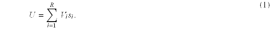
- Transmission signal vector U is then computed using the R information signals and R discrimination vectors V 1 . . . V R .
- the discrimination vectors each have N components, and transmission signal vector U also has N components.
- the transmission signal vector is then transmitted from the N base station antennas.
- the first component of U is transmitted from the first base station antenna; the second component of U is transmitted from the second antenna, and so on.
- each of the base station antennas transmits a linear combination of the components of U.
- the discrimination vectors V 1 . . . V R are preferably selected to enable remote transceiver T 1 to receive information signal s 1 , remote transceiver T 2 to receive information signal s 2 , and so on, with optimum efficiency.
- the discrimination vectors can be chosen in a variety of ways to achieve this goal.
- the discrimination vectors are chosen to be linearly independent.
- the discrimination vectors are orthogonal. Default values for an orthogonal set of discrimination vectors are preferably stored in a data bank 44 , as shown in FIG. 3 .
- Vector computation unit 46 uses the default values from data bank 44 and sends them to multipliers 36 A and 36 B.
- This first method of selecting V 1 . . . V R is preferably used when there is little or no information at the base transceiver station about the channels between the base transceiver station and the remote transceivers T 1 . . . T R .
- the channels between the base transceiver station and the remote transceivers T 1 . . . T R are characterized by channel matrices H 1 . . . H R , respectively.
- Each channel matrix is an M ⁇ N matrix, corresponding to the N base station antennas of the base transceiver station and the M remote antennas of each remote transceiver.
- the (i,j) element of H k characterizes how a signal sent from the j th base station antenna is received by the i th remote antenna of remote transceiver T k .
- the i th discrimination vector V i is selected to minimize a measure of interference ⁇ i due to the presence of i th information signal s i at remote transceivers other than T i .
- the channel matrices H 1 . . . H R must be approximately known. These channel matrices are obtained by channel characteristics extractor 50 , shown in FIG. 3 . The channel characteristics extractor then delivers the channel matrices to vector computation unit 46 .
- channel characteristics extractor 50 infers the channel matrices from transmissions from the remote transceivers. This is possible because when TDD is used, the base transceiver station transmits and receives over the same frequency channels.
- the base transceiver station transmits over different frequencies than those by which it receives.
- Channel matrices at one frequency cannot be used to reliably predict channel matrices at another frequency if the frequencies are spaced widely apart. Therefore in this case, the channel characteristics extractor preferably uses explicit feedback from the remote transceivers to determine the channel matrices. (In some embodiments where the transmit and receive frequencies are close together, channel characteristics extractor 50 infers the channel matrices from transmissions from the remote transceivers.)
- channel characteristics extractor 50 models the channels to remote transceivers T 1 . . . T R by channel matrices H 1 . . . H R , respectively.
- a control logic unit 48 determines whether (1) vector computation unit 46 uses the channel matrices to find optimum values for V 1 . . . V R , or (2) vector computation unit 46 uses the default values stored in data bank 44 .
- Control logic unit 48 also controls training unit 42 .
- the i th discrimination vector V i is selected to maximize a signal quality ⁇ i of the i th information signal s i .
- information signals s 1 . . . s R share the same conventional channel. That is, the information signals, when broadcast as transmission signal vector U, share the same conventional multiple access slots. In alternative embodiments, the information signals occupy different conventional channels.
- base station transmission processor 30 comprises interleaving and coding units 32 A and 32 B, frame formation units 34 A and 34 B, multipliers 36 A and 36 B, and adders 38 A and 38 B.
- the base station transmission processor also comprises training unit 42 , data bank 44 , vector computation unit 46 , control logic unit 48 , and channel characteristics extractor 50 .
- the channels between the base transceiver station and the remote transceivers are multipath, with each of the multiple paths having its own characteristic time delay.
- remote transceiver T 1 may simultaneously receive a first symbol sent from the base transceiver station at a time t 1 , and a second symbol sent at a time t 2 .
- the time of flight difference t 2 ⁇ t 1 corresponds to the difference in path lengths between two paths belonging to the channel to remote transceiver T 1 . Since the remote transceiver receives more than one symbol at one time, inter-symbol interference takes place.
- equalization techniques such as time filtering are well known in the art. For example when time filtering is used, linear combination of a number of symbols are transmitted at once to each remote transceiver.
- the number of simultaneous symbols transmitted to transceiver T 1 is a function of the largest time of flight difference between the channel paths, or channel taps, composing the channel to transceiver T 1 .
- the present invention also allows for time filtering.
- information signals s 1 . . . s R are replaced by information vectors S 1 . . . S R , wherein each of the information vectors comprises p components, and each component is a time delayed symbol.
- the number p is chosen to implement the time filtering described above.
- discrimination vectors V 1 . . . V R are replaced by N ⁇ p discrimination matrices V 1 . . . V R . (The matrices are distinguished from the vectors typographically by the absence of bold-face type.)
- transmission signal vector U is an N-component vector.
- frequency filtering is used.
- the base transceiver station broadcasts to each of the remote transceivers over multiple sub-carrier frequencies (like in case of OFDM) simultaneously.
- information signals s 1 . . . s R are again replaced by p-component information vectors S 1 . . . S R , but in this embodiment, p is the number of the sub-carrier frequencies used.
- the N ⁇ p discrimination matrices V 1 . . . V R are used, and in this case are optimized for frequency filtering.
- Eq. (1a) is used to compute the N-component transmission signal vector U.
- Remote transceiver T 1 comprises a remote reception processor 60 , shown in FIG. 4 .
- Remote antennas 18 A and 18 B receive signals from the base transceiver station.
- the signals from remote antennas 18 A and 18 B are down-converted by RF down-converters 62 A and 62 B, respectively, to obtain received signals Z 11 and Z 12 , respectively.
- remote transceiver T 1 has M remote antennas, and received signal vector Z 1 correspondingly has M components.
- RF down-converter 62 A operates according to known techniques and preferably comprises an RF amplifier, a mixer, a demodulator, and an analog-to-digital converter.
- Received signal Z 11 is generally a stream of complex numbers.
- RF down-converter 62 B uses amplification, frequency mixing, demodulation, and A/D techniques to produce received signal Z 12 .
- Received signal Z 12 is also a stream of complex numbers, in general.
- Received signal vector Z 1 is converted into a received data stream by remote reception processor 60 as follows.
- the components of vector Z 1 are input into a signal processor 64 that generates a reconstructed signal y 1 from the vector Z 1 .
- the reconstructed signal y 1 approximates information signal s 1 .
- reconstructed signal y 1 is obtained from received signal vector Z 1 using an M-component signature vector W 1 .
- Reconstructed signal y 1 is given by the formula:
- Eq. (2) the asterisk stands for complex conjugation and transposition.
- the multiplication implied by Eq. (2) is the standard vector dot product.
- signature vector W 1 is determined by a remote vector computation unit 66 , which outputs vector W 1 to signal processor 64 .
- the output of signal processor 64 is reconstructed signal y 1 .
- a detection, deinterleaving and decoding unit 70 processes reconstructed signal y 1 according to standard principles to produce the received data stream.
- detection, deinterleaving and decoding unit 70 detects symbols in reconstructed signal y 1 , converts the symbols to bits, then deinterleaves and decodes the bits to produce the received data stream.
- the received data stream is a bit stream.
- Signature vector W 1 is preferably selected to maximize a received signal quality parameter ⁇ 1 .
- the parameter ⁇ 1 quantifies the accuracy with which reconstructed signal y 1 duplicates information signal s 1 .
- the numerator in Eq. (3) is proportional to the signal strength at remote transceiver T 1 ; the denominator is proportional to the interference at T 1 due to signals s 2 . . . s R .
- Standard vector and matrix multiplication is implied, so that, for example, W 1 *H 1 V 1 is a scalar quantity.
- the quantities H 1 V i characterize the transmit channel from the base transceiver station to remote transceiver T 1 .
- the quantities H 1 V i are easily determined by the present system and method, since these quantities are determined by remote transceiver T 1 after receiving a transmission from the base transceiver station. This situation contrasts with conventional SDMA systems, where transmit channel information must be known at the base transceiver station prior to transmission.
- signature vector W 1 is not used to determine reconstructed signal y 1 .
- reconstructed signal y 1 depends nonlinearly upon received signal vector Z 1 .
- an estimate of H 1 V 1 is delivered to signal processor 64 from channel estimation unit 68 .
- Signal processor 64 then calculates
- 2 is then output as a symbol.
- detection, deinterleaving and decoding unit 70 does not need to detect symbols in reconstructed signal y 1 , since the symbols were already determined during the production of reconstructed signal y 1 .
- remote reception processor 60 comprises signal processor 64 , remote vector computation unit 66 , channel estimation unit 68 , and deinterleaving and decoding unit 70 .
- the R remote transceivers operate simultaneously according to the principles described above for T 1 .
- Remote transceiver T i receives a received signal vector Z i and computes a reconstructed signal y i from the vector Z i .
- the remote transceivers are adapted for time filtering; in some embodiments, the remote transceivers are adapted for frequency filtering.
- remote transceiver T 1 computes a reconstructed signal vector Y 1 instead of reconstructed signal y 1 .
- the reconstructed signal vector Y i has only one component and it is computed from p′ consecutive signal vectors Z i .
- p′ is a function of time of flight (ToF) difference between multipaths.
- frequency filtering for example when Orthogonal frequency Division Multiplexing [OFDM] is used
- the reconstructed signal vector Y i has p components computed from each signal vector Z i .
- remote transceiver T 1 comprises a remote transmission processor 80 for uplink.
- Remote transmission processor 80 is analogous to base station transmission processor 30 of FIG. 3.
- a remote data stream D 1 ′ is prepared for transmission by remote transmission processor 80 .
- Remote data stream D 1 ′ is a bit stream, and is processed by a remote interleaving and coding unit 82 and a frame formation unit 84 to produce a remote information signal s 1 ′.
- Remote information signal s 1 ′ is a symbol stream.
- the M components of the vector U 1 ′ are transmitted from the M antennas of transceiver T 1 , one component per antenna.
- M 2.
- Remote RF uplink units 98 A and 98 B convert the first and second components, respectively, of remote transmission signal vector U 1 ′ to RF signals that are transmitted from remote antennas 18 A and 18 B, respectively.
- remote processing vector W 1 ′ is selected to maximize a remote transmission quality parameter r 1 .
- the parameter r 1 is a measure of the quality of transmission from remote transceiver T 1 to the base transceiver station.
- the channel from remote transceiver T 1 to the base station antennas is characterized by an N ⁇ M return channel matrix H 1 ′.
- Return channel matrix H 1 ′ is analogous to channel matrix H 1 :
- H 1 ′ describes transmissions from remote transceiver T 1 to the base transceiver station;
- H 1 characterizes transmission from the base transceiver station to remote transceiver T 1 .
- both transmissions occur at the same frequency, as occurs in TDD, H 1 ′ can be computed from H 1 and vice versa, since the uplink and downlink channels are reciprocal.
- the matrices H 1 and H 1 ′ have to be computed independently.
- the numerator of Eq. (4) is proportional to the signal strength due to remote transceiver T 1 at the first base station antenna.
- the denominator of Eq. (4) is proportional to the sum of the intensities of the signals from T 1 that are received at the second and third base station antennas.
- remote processing vector W 1 ′ is selected to concentrate transmissions from the first remote transceiver onto the first base station antenna.
- other schemes can be used, corresponding to different choices for the orthonormal basis ⁇ e 1 . . . e N ⁇ .
- a remote uplink vector computation unit 88 computes remote processing vector W 1 ′ either using default values from data bank 90 or by optimizing remote transmission quality parameter r 1 .
- remote uplink vector computation unit 88 obtains channel matrix H 1 ′ from a remote channel characteristics extractor 92 .
- the remote channel characteristics extractor computes H 1 ′ either using feedback from the base station, or, in the TDD case, using characteristics of the downlink signal.
- a remote control logic unit 94 governs data bank 90 and remote channel characteristics extractor 92 , as well as a remote training unit 96 that sends training information to remote frame formation unit 84 .
- remote processing vector W i ′ optimizes an i th remote transmission quality parameter r i .
- r 1 ⁇ e i * ⁇ H i ′ ⁇ W i ′ ⁇ 2 / ⁇ j ⁇ 1 ⁇ e j * ⁇ H i ′ ⁇ W i ′ ⁇ 2 .
- remote transmission processor 80 comprises remote interleaving and coding unit 82 , frame formation unit 84 , remote multiplier 86 , remote uplink vector computation unit 88 , data bank 90 , remote channel characteristics extractor 92 , remote control logic unit 94 , and remote training unit 96 .
- remote information signal s 1 ′ for example, is replaced by a p-component remote information vector S 1 ′, and remote processing vector W 1 ′ is replaced by an M ⁇ p remote processing matrix W 1 ′.
- the base transceiver station receives signals from the remote transceivers during uplink.
- base station antennas 12 A and 12 B receive signals from the remote transceivers.
- the signals from base station antennas 12 A and 12 B are down-converted by RF down-converters 102 A and 102 B, respectively, to obtain base station received signals X 1 and X 2 , respectively.
- RF down-converters 102 A and 102 B each preferably comprises an RF amplifier, a frequency mixer, a demodulator, and an analog-to-digital converter.
- the received signal vector X is produced by the RF down-converters, and the components of received signal vector X are streams of complex numbers.
- the base transceiver station has an array of N base station antennas, and base station received signal vector X accordingly has N components.
- the base transceiver station comprises a reception processor 100 , shown in FIG. 6 .
- Reception processor 100 processes the components of vector X to generate base station reconstructed signals u 1 . . . u R .
- the base station reconstructed signals u 1 . . . u R are approximations to remote information signals s′ 1 . . . s′ R , respectively.
- signals u 1 . . . u R are obtained from vector X using N-component base station signature vectors V 1 ′ . . . V R ′.
- the i th base station reconstructed signal u i is given by:
- the base station signature vectors V 1 ′ . . . V R ′ are determined by a computation unit 106 .
- the vectors V 1 ′ . . . V R ′ are preferably selected to maximize base station reception quality parameters ⁇ 1 . . . ⁇ R .
- the parameters ⁇ 1 . . . ⁇ R . measure the quality of reception from remote transceivers T 1 . . . T R , respectively.
- Eq. (6) gives a signal to interference ratio for base station reconstructed signal u i .
- the return channel matrices H 1 ′ . . . H R ′ are estimated by a base station channel estimator 108 , shown in FIG. 6 .
- Reception processor 100 comprises processing units 104 A and 104 B, computation unit 106 , and base station channel estimator 108 .
- base station reconstructed signals u 1 . . . u R depend nonlinearly upon received signal vector X.
- signal us may be reconstructed using a nonlinear technique analogous to the nonlinear technique described above for producing signal y 1 during downlink.
- some embodiments use time filtering, and some use frequency filtering.
- frequency filtering such as in OFDM
- p-component base station reconstructed signal vectors U 1 . . . U R are computed instead of reconstructed signals u 1 . . . u R .
- the base station reconstructed signal vector U 1 . . . U R depend linearly upon received signal vector X
- FIG. 7 shows a graph of a performance curve 200 of the system of the present invention, and a performance curve 202 of a conventional SDMA system.
- the curves of FIG. 7 were generated in a simulation where remote transceiver T 1 receives signals having a 10 dB signal-to-noise ratio before processing.
- the x-axis of FIG. 7 gives the channel estimation accuracy, which expresses, in dB, the ratio of the matrix elements of H 1 to the uncertainty in those elements. At 0 dB, the ratio is 1:1, and the channel is 50% uncertain.
- the y-axis of FIG. 7 gives the signal to interference-plus-noise (SINR) ratio for the reconstructed signal y 1 .
- Curve 200 is always above curve 202 . Therefore the wireless system of the present invention performs better than conventional SDMA systems at all levels of channel estimation accuracy.
Abstract

Description


Claims (59)


Priority Applications (3)
| Application Number | Priority Date | Filing Date | Title |
|---|---|---|---|
| US09/544,621 US6377819B1 (en) | 2000-04-06 | 2000-04-06 | Wireless communication system using joined transmit and receive processing |
| AU2001250906A AU2001250906A1 (en) | 2000-04-06 | 2001-03-20 | Wireless communication system using joined transmit and receive processing |
| PCT/US2001/009009 WO2001078355A2 (en) | 2000-04-06 | 2001-03-20 | Wireless communication system using joined transmit and receive processing |
Applications Claiming Priority (1)
| Application Number | Priority Date | Filing Date | Title |
|---|---|---|---|
| US09/544,621 US6377819B1 (en) | 2000-04-06 | 2000-04-06 | Wireless communication system using joined transmit and receive processing |
Publications (1)
| Publication Number | Publication Date |
|---|---|
| US6377819B1 true US6377819B1 (en) | 2002-04-23 |
Family
ID=24172926
Family Applications (1)
| Application Number | Title | Priority Date | Filing Date |
|---|---|---|---|
| US09/544,621 Expired - Lifetime US6377819B1 (en) | 2000-04-06 | 2000-04-06 | Wireless communication system using joined transmit and receive processing |
Country Status (3)
| Country | Link |
|---|---|
| US (1) | US6377819B1 (en) |
| AU (1) | AU2001250906A1 (en) |
| WO (1) | WO2001078355A2 (en) |
Cited By (30)
| Publication number | Priority date | Publication date | Assignee | Title |
|---|---|---|---|---|
| US20020146060A1 (en) * | 2000-10-27 | 2002-10-10 | Ertel Richard B. | Code assignment algorithm for synchronous DS-CDMA links with SDMA using estimated spatial signature vectors |
| US20020159537A1 (en) * | 2001-04-27 | 2002-10-31 | Crilly William J. | Multipath communication methods and apparatuses |
| US20030032454A1 (en) * | 2001-08-13 | 2003-02-13 | Andrew Corporation | Architecture for digital shared antenna system to support existing base station hardware |
| US20030064753A1 (en) * | 2001-09-28 | 2003-04-03 | Kasapi Athanasios A. | System and related methods for beamforming in a multi-point communications environment |
| US20030114193A1 (en) * | 2001-12-14 | 2003-06-19 | Samsung Electronics Co. Ltd. | System and method for improving performance of an adaptive antenna array in a vehicular environment |
| US20030123404A1 (en) * | 2001-12-28 | 2003-07-03 | Kasapi Athanasios A. | System and related methods for beamforming in a multi-point communications environment |
| US20030165187A1 (en) * | 2002-03-01 | 2003-09-04 | Cognio, Inc. | System and Method for Joint Maximal Ratio Combining Using Time-Domain Based Signal Processing |
| US20030181165A1 (en) * | 2002-03-01 | 2003-09-25 | Sugar Gary L. | Systems and methods for improving range for multicast wireless communication |
| US20030186659A1 (en) * | 2002-03-30 | 2003-10-02 | Kolze Thomas J. | VOFDM receiver correlation matrix processing using factorization |
| US20030218973A1 (en) * | 2002-05-24 | 2003-11-27 | Oprea Alexandru M. | System and method for data detection in wireless communication systems |
| US6687492B1 (en) | 2002-03-01 | 2004-02-03 | Cognio, Inc. | System and method for antenna diversity using joint maximal ratio combining |
| US20040023621A1 (en) * | 2002-07-30 | 2004-02-05 | Sugar Gary L. | System and method for multiple-input multiple-output (MIMO) radio communication |
| US20040048584A1 (en) * | 2002-09-10 | 2004-03-11 | Chandra Vaidyanathan | Techniques for correcting for phase and amplitude offsets in a MIMO radio device |
| US20040072546A1 (en) * | 2002-03-01 | 2004-04-15 | Cognio, Inc. | System and Method for Antenna Diversity Using Equal Power Joint Maximal Ratio Combining |
| US20040136466A1 (en) * | 2002-03-01 | 2004-07-15 | Cognio, Inc. | System and Method for Joint Maximal Ratio Combining Using Time-Domain Based Signal Processing |
| US20040190636A1 (en) * | 2003-03-31 | 2004-09-30 | Oprea Alexandru M. | System and method for wireless communication systems |
| US20040209579A1 (en) * | 2003-04-10 | 2004-10-21 | Chandra Vaidyanathan | System and method for transmit weight computation for vector beamforming radio communication |
| US20040224648A1 (en) * | 2002-03-21 | 2004-11-11 | Sugar Gary L. | Efficiency of power amplifers in devices using transmit beamforming |
| US20040259556A1 (en) * | 2003-02-13 | 2004-12-23 | Baruch Czys | Wireless network with intensive frequency reuse |
| US20050157683A1 (en) * | 2000-06-02 | 2005-07-21 | Nokia Networks Oy | Closed loop feedback system for improved down link performance |
| US20050254437A1 (en) * | 2004-05-11 | 2005-11-17 | Erven Niels V | SDMA system using MU-SIMO for the uplink and MU-MISO for the downlink |
| US20060154607A1 (en) * | 2002-10-16 | 2006-07-13 | .Andrew Corporation | System and method for estimating the multi-path delays in a signal using a spatially blind antenna array |
| US7079870B2 (en) | 2003-06-09 | 2006-07-18 | Ipr Licensing, Inc. | Compensation techniques for group delay effects in transmit beamforming radio communication |
| US20060285483A1 (en) * | 2005-06-15 | 2006-12-21 | Samsung Electronics Co., Ltd. | Apparatus and method for multiplexing broadcast and unicast traffic in a multi-carrier wireless network |
| EP1763269A1 (en) * | 2004-06-28 | 2007-03-14 | Sanyo Electric Co., Ltd. | Channel allocation method and base station device using the same |
| US20080165883A1 (en) * | 2005-09-30 | 2008-07-10 | Huawei Technologies Co., Ltd. | Resource allocation method for mimo-ofdm of multi-user access systems |
| US20090080500A1 (en) * | 2007-09-21 | 2009-03-26 | Tarik Muharemovic | Reference Signal Structure for OFDM Based Transmissions |
| US20100210214A1 (en) * | 2009-02-18 | 2010-08-19 | Clear Wireless Llc | Method for reducing time of flight interference in a wireless communication network |
| US8890744B1 (en) | 1999-04-07 | 2014-11-18 | James L. Geer | Method and apparatus for the detection of objects using electromagnetic wave attenuation patterns |
| US20170212228A1 (en) * | 2014-07-09 | 2017-07-27 | Softkinetic Sensors Nv | A method for binning time-of-flight data |
Families Citing this family (1)
| Publication number | Priority date | Publication date | Assignee | Title |
|---|---|---|---|---|
| US8391322B2 (en) | 2003-07-09 | 2013-03-05 | Broadcom Corporation | Method and system for single weight (SW) antenna system for spatial multiplexing (SM) MIMO system for WCDMA/HSDPA |
Citations (8)
| Publication number | Priority date | Publication date | Assignee | Title |
|---|---|---|---|---|
| WO1998009381A1 (en) | 1996-08-29 | 1998-03-05 | The Board Of Trustees Of The Leland Stanford Junior University | High capacity wireless communication using spatial subchannels |
| US5815488A (en) | 1995-09-28 | 1998-09-29 | Cable Television Laboratories, Inc. | Multiple user access method using OFDM |
| US5933421A (en) | 1997-02-06 | 1999-08-03 | At&T Wireless Services Inc. | Method for frequency division duplex communications |
| US5999800A (en) * | 1996-04-18 | 1999-12-07 | Korea Telecom Freetel Co., Ltd. | Design technique of an array antenna, and telecommunication system and method utilizing the array antenna |
| EP0980938A2 (en) * | 1998-08-20 | 2000-02-23 | Konrad Lehrhuber | Support assembly for buildings construction and method of making the same |
| US6064662A (en) | 1994-04-28 | 2000-05-16 | At&T Corp | System and method for optimizing spectral efficiency using time-frequency-code slicing |
| US6154661A (en) * | 1997-12-10 | 2000-11-28 | Arraycomm, Inc. | Transmitting on the downlink using one or more weight vectors determined to achieve a desired radiation pattern |
| US6185440B1 (en) * | 1997-12-10 | 2001-02-06 | Arraycomm, Inc. | Method for sequentially transmitting a downlink signal from a communication station that has an antenna array to achieve an omnidirectional radiation |
Family Cites Families (1)
| Publication number | Priority date | Publication date | Assignee | Title |
|---|---|---|---|---|
| US5828658A (en) * | 1991-12-12 | 1998-10-27 | Arraycomm, Inc. | Spectrally efficient high capacity wireless communication systems with spatio-temporal processing |
-
2000
- 2000-04-06 US US09/544,621 patent/US6377819B1/en not_active Expired - Lifetime
-
2001
- 2001-03-20 AU AU2001250906A patent/AU2001250906A1/en not_active Abandoned
- 2001-03-20 WO PCT/US2001/009009 patent/WO2001078355A2/en active Application Filing
Patent Citations (9)
| Publication number | Priority date | Publication date | Assignee | Title |
|---|---|---|---|---|
| US6064662A (en) | 1994-04-28 | 2000-05-16 | At&T Corp | System and method for optimizing spectral efficiency using time-frequency-code slicing |
| US5815488A (en) | 1995-09-28 | 1998-09-29 | Cable Television Laboratories, Inc. | Multiple user access method using OFDM |
| US5999800A (en) * | 1996-04-18 | 1999-12-07 | Korea Telecom Freetel Co., Ltd. | Design technique of an array antenna, and telecommunication system and method utilizing the array antenna |
| WO1998009381A1 (en) | 1996-08-29 | 1998-03-05 | The Board Of Trustees Of The Leland Stanford Junior University | High capacity wireless communication using spatial subchannels |
| US6144711A (en) * | 1996-08-29 | 2000-11-07 | Cisco Systems, Inc. | Spatio-temporal processing for communication |
| US5933421A (en) | 1997-02-06 | 1999-08-03 | At&T Wireless Services Inc. | Method for frequency division duplex communications |
| US6154661A (en) * | 1997-12-10 | 2000-11-28 | Arraycomm, Inc. | Transmitting on the downlink using one or more weight vectors determined to achieve a desired radiation pattern |
| US6185440B1 (en) * | 1997-12-10 | 2001-02-06 | Arraycomm, Inc. | Method for sequentially transmitting a downlink signal from a communication station that has an antenna array to achieve an omnidirectional radiation |
| EP0980938A2 (en) * | 1998-08-20 | 2000-02-23 | Konrad Lehrhuber | Support assembly for buildings construction and method of making the same |
Non-Patent Citations (1)
| Title |
|---|
| Paulraj, A., Taxonomy of space-time processing for wireless networks, IEE Proc-Radar Sonar Navig., vol. 145, No. 1, Feb. 1998. |
Cited By (93)
| Publication number | Priority date | Publication date | Assignee | Title |
|---|---|---|---|---|
| US9551785B1 (en) | 1999-04-07 | 2017-01-24 | James L. Geer | Method and apparatus for the detection of objects using electromagnetic wave attenuation patterns |
| US8890744B1 (en) | 1999-04-07 | 2014-11-18 | James L. Geer | Method and apparatus for the detection of objects using electromagnetic wave attenuation patterns |
| US7792206B2 (en) | 2000-06-02 | 2010-09-07 | Juha Ylitalo | Closed loop feedback system for improved down link performance |
| US20050157683A1 (en) * | 2000-06-02 | 2005-07-21 | Nokia Networks Oy | Closed loop feedback system for improved down link performance |
| US20050157684A1 (en) * | 2000-06-02 | 2005-07-21 | Nokia Networks Oy | Closed loop feedback system for improved down link performance |
| US7139324B1 (en) * | 2000-06-02 | 2006-11-21 | Nokia Networks Oy | Closed loop feedback system for improved down link performance |
| US7844010B2 (en) | 2000-06-02 | 2010-11-30 | Juha Ylitalo | Closed loop feedback system for improved down link performance |
| US20100322337A1 (en) * | 2000-06-02 | 2010-12-23 | Juha Ylitalo | Closed loop feedback system for improved down link performance |
| US8442144B2 (en) | 2000-06-02 | 2013-05-14 | Intellectual Ventures I Llc | Closed loop feedback system for improved down link performance |
| US20020146060A1 (en) * | 2000-10-27 | 2002-10-10 | Ertel Richard B. | Code assignment algorithm for synchronous DS-CDMA links with SDMA using estimated spatial signature vectors |
| US7050480B2 (en) * | 2000-10-27 | 2006-05-23 | L3 Communications Corporation | Code assignment algorithm for synchronous DS-CDMA links with SDMA using estimated spatial signature vectors |
| US7177369B2 (en) * | 2001-04-27 | 2007-02-13 | Vivato, Inc. | Multipath communication methods and apparatuses |
| US20020159537A1 (en) * | 2001-04-27 | 2002-10-31 | Crilly William J. | Multipath communication methods and apparatuses |
| US20030032454A1 (en) * | 2001-08-13 | 2003-02-13 | Andrew Corporation | Architecture for digital shared antenna system to support existing base station hardware |
| US7003322B2 (en) | 2001-08-13 | 2006-02-21 | Andrew Corporation | Architecture for digital shared antenna system to support existing base station hardware |
| US7043270B2 (en) | 2001-08-13 | 2006-05-09 | Andrew Corporation | Shared tower system for accomodating multiple service providers |
| US20030064753A1 (en) * | 2001-09-28 | 2003-04-03 | Kasapi Athanasios A. | System and related methods for beamforming in a multi-point communications environment |
| US20030114193A1 (en) * | 2001-12-14 | 2003-06-19 | Samsung Electronics Co. Ltd. | System and method for improving performance of an adaptive antenna array in a vehicular environment |
| US7139593B2 (en) * | 2001-12-14 | 2006-11-21 | Samsung Electronics Co., Ltd. | System and method for improving performance of an adaptive antenna array in a vehicular environment |
| US20070165552A1 (en) * | 2001-12-28 | 2007-07-19 | Arraycomm Llc. | System and related methods for beamforming in a multi-point communications environment |
| US20030123404A1 (en) * | 2001-12-28 | 2003-07-03 | Kasapi Athanasios A. | System and related methods for beamforming in a multi-point communications environment |
| US7817590B2 (en) | 2001-12-28 | 2010-10-19 | Intel Corporation | System and related methods for beamforming in a multi-point communications environment |
| US7660276B2 (en) | 2001-12-28 | 2010-02-09 | Intel Corporation | System and related methods for beamforming in a multi-point communications environment |
| US7206293B2 (en) | 2001-12-28 | 2007-04-17 | Arraycomm Llc | System and related methods for beamforming in a multi-point communications environment |
| US20100034131A1 (en) * | 2001-12-28 | 2010-02-11 | Kasapi Athanasios A | System and Related Methods for Beamforming in a Multi-Point Communications Environment |
| US6862456B2 (en) * | 2002-03-01 | 2005-03-01 | Cognio, Inc. | Systems and methods for improving range for multicast wireless communication |
| US20040136466A1 (en) * | 2002-03-01 | 2004-07-15 | Cognio, Inc. | System and Method for Joint Maximal Ratio Combining Using Time-Domain Based Signal Processing |
| US20050215202A1 (en) * | 2002-03-01 | 2005-09-29 | Sugar Gary L | System and method for antenna diversity using equal power joint maximal ratio combining |
| US6965762B2 (en) | 2002-03-01 | 2005-11-15 | Ipr Licensing, Inc. | System and method for antenna diversity using joint maximal ratio combining |
| USRE47732E1 (en) | 2002-03-01 | 2019-11-19 | Ipr Licensing, Inc. | System and method for antenna diversity using equal power joint maximal ratio combining |
| US20060013327A1 (en) * | 2002-03-01 | 2006-01-19 | Ipr Licensing, Inc. | Apparatus for antenna diversity using joint maximal ratio combining |
| US7570921B2 (en) | 2002-03-01 | 2009-08-04 | Ipr Licensing, Inc. | Systems and methods for improving range for multicast wireless communication |
| US6873651B2 (en) | 2002-03-01 | 2005-03-29 | Cognio, Inc. | System and method for joint maximal ratio combining using time-domain signal processing |
| USRE46750E1 (en) | 2002-03-01 | 2018-03-06 | Ipr Licensing, Inc. | System and method for antenna diversity using equal power joint maximal ratio combining |
| US20030165187A1 (en) * | 2002-03-01 | 2003-09-04 | Cognio, Inc. | System and Method for Joint Maximal Ratio Combining Using Time-Domain Based Signal Processing |
| US7573945B2 (en) | 2002-03-01 | 2009-08-11 | Ipr Licensing, Inc. | System and method for joint maximal ratio combining using time-domain based signal processing |
| US20090239486A1 (en) * | 2002-03-01 | 2009-09-24 | Ipr Licensing, Inc. | Apparatus for antenna diversity using joint maximal ratio combining |
| USRE45425E1 (en) | 2002-03-01 | 2015-03-17 | Ipr Licensing, Inc. | System and method for antenna diversity using equal power joint maximal ratio combining |
| US20030181165A1 (en) * | 2002-03-01 | 2003-09-25 | Sugar Gary L. | Systems and methods for improving range for multicast wireless communication |
| US20090285146A1 (en) * | 2002-03-01 | 2009-11-19 | Ipr Licensing, Inc. | Methods for improving range for multicast wireless communication |
| US20080014977A1 (en) * | 2002-03-01 | 2008-01-17 | Ipr Licensing Inc. | System and method for antenna diversity using equal power joint maximal ratio combining |
| US20040219937A1 (en) * | 2002-03-01 | 2004-11-04 | Sugar Gary L. | Systems and methods for improving range for multicast wireless communication |
| US20090296848A1 (en) * | 2002-03-01 | 2009-12-03 | Ipr Licensing, Inc. | Joint maximal ratio combining using time-domauin based signal processing |
| US7881674B2 (en) | 2002-03-01 | 2011-02-01 | Ipr Licensing, Inc. | System and method for antenna diversity using equal power joint maximal ratio combining |
| US20040087275A1 (en) * | 2002-03-01 | 2004-05-06 | Sugar Gary L. | System and method for antenna diversity using joint maximal ratio combining |
| US6687492B1 (en) | 2002-03-01 | 2004-02-03 | Cognio, Inc. | System and method for antenna diversity using joint maximal ratio combining |
| US7545778B2 (en) | 2002-03-01 | 2009-06-09 | Ipr Licensing, Inc. | Apparatus for antenna diversity using joint maximal ratio combining |
| US7245881B2 (en) | 2002-03-01 | 2007-07-17 | Ipr Licensing, Inc. | System and method for antenna diversity using equal power joint maximal ratio combining |
| US20040072546A1 (en) * | 2002-03-01 | 2004-04-15 | Cognio, Inc. | System and Method for Antenna Diversity Using Equal Power Joint Maximal Ratio Combining |
| US7899414B2 (en) | 2002-03-21 | 2011-03-01 | Ipr Licensing, Inc. | Control of power amplifiers in devices using transmit beamforming |
| US20090285331A1 (en) * | 2002-03-21 | 2009-11-19 | Ipr Licensing, Inc. | Control of power amplifiers in devices using transmit beamforming |
| US20060116087A1 (en) * | 2002-03-21 | 2006-06-01 | Ipr Licensing, Inc. | Control of power amplifiers in devices using transmit beamforming |
| US20040224648A1 (en) * | 2002-03-21 | 2004-11-11 | Sugar Gary L. | Efficiency of power amplifers in devices using transmit beamforming |
| US6993299B2 (en) | 2002-03-21 | 2006-01-31 | Ipr Licensing, Inc. | Efficiency of power amplifiers in devices using transmit beamforming |
| US7565117B2 (en) | 2002-03-21 | 2009-07-21 | Ipr Licensing, Inc. | Control of power amplifiers in devices using transmit beamforming |
| US6947715B2 (en) * | 2002-03-30 | 2005-09-20 | Broadcom Corporation | VOFDM receiver correlation matrix processing using factorization |
| US20030186659A1 (en) * | 2002-03-30 | 2003-10-02 | Kolze Thomas J. | VOFDM receiver correlation matrix processing using factorization |
| US20030218973A1 (en) * | 2002-05-24 | 2003-11-27 | Oprea Alexandru M. | System and method for data detection in wireless communication systems |
| US7327800B2 (en) | 2002-05-24 | 2008-02-05 | Vecima Networks Inc. | System and method for data detection in wireless communication systems |
| US20040023621A1 (en) * | 2002-07-30 | 2004-02-05 | Sugar Gary L. | System and method for multiple-input multiple-output (MIMO) radio communication |
| US7194237B2 (en) | 2002-07-30 | 2007-03-20 | Ipr Licensing Inc. | System and method for multiple-input multiple-output (MIMO) radio communication |
| US20040219892A1 (en) * | 2002-09-10 | 2004-11-04 | Chandra Vaidyanathan | Techniques for correcting for phase and amplitude offsets in a mimo radio device |
| US20040048584A1 (en) * | 2002-09-10 | 2004-03-11 | Chandra Vaidyanathan | Techniques for correcting for phase and amplitude offsets in a MIMO radio device |
| US7031669B2 (en) * | 2002-09-10 | 2006-04-18 | Cognio, Inc. | Techniques for correcting for phase and amplitude offsets in a MIMO radio device |
| US7236750B2 (en) | 2002-09-10 | 2007-06-26 | Ipr Licensing Inc. | Techniques for correcting for phase and amplitude offsets in a MIMO radio device |
| US20080194207A1 (en) * | 2002-10-16 | 2008-08-14 | Andrew Corporation | System and method for estimating the multi-path delays in a signal using a spatially blind antenna array |
| US7379757B2 (en) * | 2002-10-16 | 2008-05-27 | Andrew Corporation | System and method for estimating the multi-path delays in a signal using a spatially blind antenna array |
| US20060154607A1 (en) * | 2002-10-16 | 2006-07-13 | .Andrew Corporation | System and method for estimating the multi-path delays in a signal using a spatially blind antenna array |
| US7778608B2 (en) * | 2002-10-16 | 2010-08-17 | Andrew Llc | System and method for estimating the multi-path delays in a signal using a spatially blind antenna array |
| US20040259556A1 (en) * | 2003-02-13 | 2004-12-23 | Baruch Czys | Wireless network with intensive frequency reuse |
| US7327795B2 (en) | 2003-03-31 | 2008-02-05 | Vecima Networks Inc. | System and method for wireless communication systems |
| US20040190636A1 (en) * | 2003-03-31 | 2004-09-30 | Oprea Alexandru M. | System and method for wireless communication systems |
| US7099678B2 (en) | 2003-04-10 | 2006-08-29 | Ipr Licensing, Inc. | System and method for transmit weight computation for vector beamforming radio communication |
| US20040209579A1 (en) * | 2003-04-10 | 2004-10-21 | Chandra Vaidyanathan | System and method for transmit weight computation for vector beamforming radio communication |
| US20080095260A1 (en) * | 2003-06-09 | 2008-04-24 | Ipr Licensing Inc. | Compensation techniques for group delay effects in transmit beamforming radio communication |
| US20060258403A1 (en) * | 2003-06-09 | 2006-11-16 | Ipr Licensing Inc. | Compensation techniques for group delay effects in transmit beamforming radio communication |
| US7308287B2 (en) | 2003-06-09 | 2007-12-11 | Ipr Licensing Inc. | Compensation techniques for group delay effects in transmit beamforming radio communication |
| US7079870B2 (en) | 2003-06-09 | 2006-07-18 | Ipr Licensing, Inc. | Compensation techniques for group delay effects in transmit beamforming radio communication |
| US7257088B2 (en) * | 2004-05-11 | 2007-08-14 | 3Com Corporation | SDMA system using MU-SIMO for the uplink and MU-MISO for the downlink |
| US20050254437A1 (en) * | 2004-05-11 | 2005-11-17 | Erven Niels V | SDMA system using MU-SIMO for the uplink and MU-MISO for the downlink |
| EP1763269A4 (en) * | 2004-06-28 | 2013-08-14 | Kyocera Corp | Channel allocation method and base station device using the same |
| EP1763269A1 (en) * | 2004-06-28 | 2007-03-14 | Sanyo Electric Co., Ltd. | Channel allocation method and base station device using the same |
| US7894818B2 (en) * | 2005-06-15 | 2011-02-22 | Samsung Electronics Co., Ltd. | Apparatus and method for multiplexing broadcast and unicast traffic in a multi-carrier wireless network |
| US20060285483A1 (en) * | 2005-06-15 | 2006-12-21 | Samsung Electronics Co., Ltd. | Apparatus and method for multiplexing broadcast and unicast traffic in a multi-carrier wireless network |
| US8238462B2 (en) * | 2005-09-30 | 2012-08-07 | Huawei Technologies Co., Ltd. | Resource allocation method for MIMO-OFDM of multi-user access systems |
| US20080165883A1 (en) * | 2005-09-30 | 2008-07-10 | Huawei Technologies Co., Ltd. | Resource allocation method for mimo-ofdm of multi-user access systems |
| US20090080500A1 (en) * | 2007-09-21 | 2009-03-26 | Tarik Muharemovic | Reference Signal Structure for OFDM Based Transmissions |
| US20130301538A1 (en) * | 2007-09-21 | 2013-11-14 | Texas Instruments Incorporated | Reference Signal Structure for OFDM Based Transmissions |
| US8170126B2 (en) * | 2007-09-21 | 2012-05-01 | Texas Instruments Incorporated | Reference signal structure for OFDM based transmissions |
| US8068786B2 (en) | 2009-02-18 | 2011-11-29 | Clear Wireless Llc | Method for reducing time of flight interference in a wireless communication network |
| US20100210214A1 (en) * | 2009-02-18 | 2010-08-19 | Clear Wireless Llc | Method for reducing time of flight interference in a wireless communication network |
| US20170212228A1 (en) * | 2014-07-09 | 2017-07-27 | Softkinetic Sensors Nv | A method for binning time-of-flight data |
| US11047962B2 (en) * | 2014-07-09 | 2021-06-29 | Sony Depthsensing Solutions Sa/Nv | Method for binning time-of-flight data |
Also Published As
| Publication number | Publication date |
|---|---|
| AU2001250906A1 (en) | 2001-10-23 |
| WO2001078355A2 (en) | 2001-10-18 |
| WO2001078355A3 (en) | 2002-07-18 |
Similar Documents
| Publication | Publication Date | Title |
|---|---|---|
| US6377819B1 (en) | Wireless communication system using joined transmit and receive processing | |
| US10523284B2 (en) | Transmission method and transmission apparatus | |
| US10856305B2 (en) | Multi-user MIMO systems and methods | |
| US7907912B2 (en) | Apparatus and method for eliminating multi-user interference | |
| US7933357B2 (en) | Apparatus and method for transmission and reception in a multi-user MIMO communication system | |
| EP1366579B1 (en) | Method for controlling the weighting of a data signal in the at least two antenna elements of a radio connection unit, module and communications system | |
| US8290539B2 (en) | Beam selection in open loop MU-MIMO | |
| EP1742405B1 (en) | Method for channel estimation with spatial division multiplexing in an orthogonal frequency division multiplexing system with multiple antennas | |
| JP4173137B2 (en) | MIMO signal processing method with rank adaptive adaptation of data transmission rate | |
| US7139328B2 (en) | Method and apparatus for closed loop data transmission | |
| US7110378B2 (en) | Channel aware optimal space-time signaling for wireless communication over wideband multipath channels | |
| KR101373808B1 (en) | Apparatus and method for deciding channel quality indicator using beamforming in multiple antenna system | |
| EP1192737B1 (en) | Diversity transmission method and system | |
| CN1830158B (en) | System and method for transmitting/receiving a signal in a mobile communication system using a multiple input multiple output adaptive antenna array scheme | |
| US8891648B2 (en) | System for transmitting and receiving channel state information | |
| US20020009156A1 (en) | Transmit diversity method and system | |
| EP1643661A2 (en) | MIMO system with adaptive switching of transmission scheme | |
| US9887757B2 (en) | Method and apparatus for efficient channel state information dissemination for MU-MIMO transmission schemes based on outdated channel state information | |
| WO2006068413A1 (en) | Method for selecting switched beam using pilot signal and system thereof | |
| KR20090066198A (en) | Mobile terminal and base station in mimo system and method for combining receive signals | |
| EP2266243B1 (en) | Reduced complexity frequency band and virtual antenna combination selection | |
| US20030021351A1 (en) | System and method for circulant transmit diversity | |
| JP2009527184A (en) | Multi-antenna communication method with improved channel correlation utilization | |
| Koorapaty et al. | Delta modulation for channel feedback in transmit diversity systems | |
| CN113014371A (en) | Airspace TDD wireless communication method based on non-orthogonal multiple access, base station and terminal |
Legal Events
| Date | Code | Title | Description |
|---|---|---|---|
| AS | Assignment |
Owner name: GIGABIT WIRELESS, INC, CALIFORNIA Free format text: ASSIGNMENT OF ASSIGNORS INTEREST;ASSIGNORS:GESBERT, DAVID;PAULRAJ, AROGYASWAMI J.;SEBASTIAN, PEROOR K.;REEL/FRAME:010691/0482 Effective date: 20000405 |
|
| AS | Assignment |
Owner name: IOSPAN WIRELESS, INC., CALIFORNIA Free format text: ASSIGNMENT OF ASSIGNORS INTEREST;ASSIGNOR:GIGABIT WIRELESS, INC.;REEL/FRAME:011336/0876 Effective date: 19981218 |
|
| AS | Assignment |
Owner name: INTEL CORPORATION, CALIFORNIA Free format text: ASSIGNMENT OF ASSIGNORS INTEREST;ASSIGNOR:IOSPAN WIRELESS, INC.;REEL/FRAME:014027/0124 Effective date: 20020918 |
|
| RF | Reissue application filed |
Effective date: 20040422 |
|
| FEPP | Fee payment procedure |
Free format text: PAT HOLDER NO LONGER CLAIMS SMALL ENTITY STATUS, ENTITY STATUS SET TO UNDISCOUNTED (ORIGINAL EVENT CODE: STOL); ENTITY STATUS OF PATENT OWNER: LARGE ENTITY |
|
| REFU | Refund |
Free format text: REFUND - SURCHARGE, PETITION TO ACCEPT PYMT AFTER EXP, UNINTENTIONAL (ORIGINAL EVENT CODE: R2551); ENTITY STATUS OF PATENT OWNER: LARGE ENTITY |
|
| FEPP | Fee payment procedure |
Free format text: PAYOR NUMBER ASSIGNED (ORIGINAL EVENT CODE: ASPN); ENTITY STATUS OF PATENT OWNER: LARGE ENTITY |
|
| FPAY | Fee payment |
Year of fee payment: 4 |
|
| FEPP | Fee payment procedure |
Free format text: PETITION RELATED TO MAINTENANCE FEES GRANTED (ORIGINAL EVENT CODE: PMFG); ENTITY STATUS OF PATENT OWNER: LARGE ENTITY |
|
| REMI | Maintenance fee reminder mailed | ||
| REIN | Reinstatement after maintenance fee payment confirmed | ||
| FP | Lapsed due to failure to pay maintenance fee |
Effective date: 20100423 |
|
| FPAY | Fee payment |
Year of fee payment: 8 |
|
| PRDP | Patent reinstated due to the acceptance of a late maintenance fee |
Effective date: 20101018 |
|
| STCF | Information on status: patent grant |
Free format text: PATENTED CASE |
|
| SULP | Surcharge for late payment | ||
| FPAY | Fee payment |
Year of fee payment: 12 |