US6151357A - Method and apparatus for displaying a visual indication of a transmission status - Google Patents
Method and apparatus for displaying a visual indication of a transmission status Download PDFInfo
- Publication number
- US6151357A US6151357A US09/008,956 US895698A US6151357A US 6151357 A US6151357 A US 6151357A US 895698 A US895698 A US 895698A US 6151357 A US6151357 A US 6151357A
- Authority
- US
- United States
- Prior art keywords
- transmission
- status
- visual indicator
- communication link
- agent
- Prior art date
- Legal status (The legal status is an assumption and is not a legal conclusion. Google has not performed a legal analysis and makes no representation as to the accuracy of the status listed.)
- Expired - Lifetime
Links
Images


Classifications
-
- H—ELECTRICITY
- H04—ELECTRIC COMMUNICATION TECHNIQUE
- H04L—TRANSMISSION OF DIGITAL INFORMATION, e.g. TELEGRAPHIC COMMUNICATION
- H04L67/00—Network arrangements or protocols for supporting network services or applications
- H04L67/14—Session management
-
- H—ELECTRICITY
- H04—ELECTRIC COMMUNICATION TECHNIQUE
- H04L—TRANSMISSION OF DIGITAL INFORMATION, e.g. TELEGRAPHIC COMMUNICATION
- H04L67/00—Network arrangements or protocols for supporting network services or applications
- H04L67/34—Network arrangements or protocols for supporting network services or applications involving the movement of software or configuration parameters
-
- H—ELECTRICITY
- H04—ELECTRIC COMMUNICATION TECHNIQUE
- H04L—TRANSMISSION OF DIGITAL INFORMATION, e.g. TELEGRAPHIC COMMUNICATION
- H04L67/00—Network arrangements or protocols for supporting network services or applications
- H04L67/50—Network services
- H04L67/75—Indicating network or usage conditions on the user display
-
- H—ELECTRICITY
- H04—ELECTRIC COMMUNICATION TECHNIQUE
- H04L—TRANSMISSION OF DIGITAL INFORMATION, e.g. TELEGRAPHIC COMMUNICATION
- H04L9/00—Cryptographic mechanisms or cryptographic arrangements for secret or secure communications; Network security protocols
- H04L9/40—Network security protocols
-
- H—ELECTRICITY
- H04—ELECTRIC COMMUNICATION TECHNIQUE
- H04M—TELEPHONIC COMMUNICATION
- H04M3/00—Automatic or semi-automatic exchanges
- H04M3/42—Systems providing special services or facilities to subscribers
- H04M3/50—Centralised arrangements for answering calls; Centralised arrangements for recording messages for absent or busy subscribers ; Centralised arrangements for recording messages
- H04M3/51—Centralised call answering arrangements requiring operator intervention, e.g. call or contact centers for telemarketing
- H04M3/5183—Call or contact centers with computer-telephony arrangements
- H04M3/5191—Call or contact centers with computer-telephony arrangements interacting with the Internet
-
- H—ELECTRICITY
- H04—ELECTRIC COMMUNICATION TECHNIQUE
- H04L—TRANSMISSION OF DIGITAL INFORMATION, e.g. TELEGRAPHIC COMMUNICATION
- H04L69/00—Network arrangements, protocols or services independent of the application payload and not provided for in the other groups of this subclass
- H04L69/30—Definitions, standards or architectural aspects of layered protocol stacks
- H04L69/32—Architecture of open systems interconnection [OSI] 7-layer type protocol stacks, e.g. the interfaces between the data link level and the physical level
- H04L69/322—Intralayer communication protocols among peer entities or protocol data unit [PDU] definitions
- H04L69/329—Intralayer communication protocols among peer entities or protocol data unit [PDU] definitions in the application layer [OSI layer 7]
-
- H—ELECTRICITY
- H04—ELECTRIC COMMUNICATION TECHNIQUE
- H04M—TELEPHONIC COMMUNICATION
- H04M2201/00—Electronic components, circuits, software, systems or apparatus used in telephone systems
- H04M2201/38—Displays
-
- H—ELECTRICITY
- H04—ELECTRIC COMMUNICATION TECHNIQUE
- H04M—TELEPHONIC COMMUNICATION
- H04M3/00—Automatic or semi-automatic exchanges
- H04M3/42—Systems providing special services or facilities to subscribers
- H04M3/50—Centralised arrangements for answering calls; Centralised arrangements for recording messages for absent or busy subscribers ; Centralised arrangements for recording messages
- H04M3/51—Centralised call answering arrangements requiring operator intervention, e.g. call or contact centers for telemarketing
- H04M3/5125—Centralised call answering arrangements requiring operator intervention, e.g. call or contact centers for telemarketing with remote located operators
-
- H—ELECTRICITY
- H04—ELECTRIC COMMUNICATION TECHNIQUE
- H04M—TELEPHONIC COMMUNICATION
- H04M3/00—Automatic or semi-automatic exchanges
- H04M3/60—Semi-automatic systems, i.e. in which the numerical selection of the outgoing line is under the control of an operator
- H04M3/62—Keyboard equipment
Definitions
- the present invention relates to communication systems. More specifically, the invention provides a system that displays a visual indicator of the status of a transmission across a communication link.
- Various types of systems are available for transmitting data from a transmission source to a transmission destination across a communication link.
- the time required to transmit data from a source to a destination depends on several factors including the amount of data to be transmitted, the speed or bandwidth of the communication link, and the speed at which data can be prepared for transmission by the transmission source.
- the speed at which data can be transmitted across the communication link may vary depending on other data transmissions using common paths or devices along the communication link. Thus, the time required to complete a particular data transmission is difficult to estimate if the data transmission speed across the communication link cannot be accurately determined.
- the transmission time can vary significantly depending on the congestion of the various communication paths and communication devices along the communication link from the source to the destination. Additionally, the transmission time will vary based on the size of the web page being transmitted.
- the transmission initiator i.e., the individual transmitting the web page
- the transmission initiator cannot determine the status of the transmission unless a person at the destination contacts the transmission initiator (e.g., by placing a telephone call to the transmission initiator). Without communicating with a person at the transmission destination, the transmission initiator is unable to determine when a particular transmission has been completed and is unable to determine whether the transmission has been delayed due to congestion along the communication link.
- the present invention is related to a system capable of displaying a visual indicator that represents the status of a transmission across a communication link.
- Embodiments of the invention provide a system that displays different visual indicators based on whether the transmission is complete, incomplete, or the communication link is congested. By using this visual indicator, an individual or system is able to determine when a particular transmission has been completed.
- An embodiment of the invention indicates a transmission status by determining a status of a transmission across a communication link based on information received from a transmission destination.
- a first visual indicator representing the transmission status is displayed if the transmission is incomplete.
- a second visual indicator representing the transmission status is displayed if the transmission is complete.
- Embodiments of the invention display a third visual indicator representing the transmission status if the communication link is congested.
- An embodiment of the invention displays the visual indicators proximate a transmission source.
- a particular embodiment of the invention determines the status of the transmission across the communication link by transmitting instructions to the transmission destination.
- the instructions cause the transmission destination to generate the transmission status and provide the generated transmission status to a transmission source.
- FIG. 1 illustrates an embodiment of a transaction processing environment in which the present invention may be used.
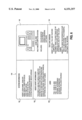
- FIG. 2 illustrates an embodiment of a transaction processing environment including a server, an agent computer system, a customer computer system, and a transaction processing system coupled together using various networks.
- FIG. 3 illustrates an embodiment of a control server.
- FIG. 4 illustrates an embodiment of a system architecture for communicating information between various devices in a transaction processing environment.
- FIG. 5 is a flow diagram illustrating an embodiment of a procedure for communicating information between various devices using the architecture of FIG. 4.
- FIG. 6 illustrates an embodiment of various windows displayed to an agent using the agent's computer.
- FIG. 7 is a flow diagram illustrating an embodiment of a procedure for displaying visual indicators representing transmission status.
- FIG. 8 is a flow diagram illustrating an embodiment of a procedure for determining the status of a transmission across a communication link.
- FIGS. 9A-9C illustrate examples of visual indicators that represent transmission status.
- FIG. 10 illustrates an embodiment of a computer system that can be used with the present invention.
- the present invention is related to a system capable of displaying a visual indicator that represents the status of a transmission across a communication link.
- Embodiments of the invention provide a system that displays different visual indicators based on whether the transmission is complete, incomplete, or the communication link is congested. Additional visual indicators may be provided to indicate other transmission states, such as an aborted transmission. The appropriate visual indicator is displayed proximate the transmission source or displayed to the initiator of the transmission. By using this visual indicator, a transaction initiator is able to determine when a particular transmission has been completed.
- the teachings of the present invention can be used with any type of data transmission across any communication link.
- a particular communication link may include multiple paths or links across multiple networks through multiple devices (e.g., network switches or network routers).
- Exemplary transactions in a transaction processing environment include telephone calls, facsimile transmissions, electronic mail (e-mail), video sessions, or network sessions (such as an Internet session).
- a particular transaction can be either inbound (e.g., received by a transaction processing system) or outbound (e.g., transmitted from a transaction processing system).
- a transaction processing system is any device capable of receiving, transmitting, queuing, routing, or otherwise processing a transaction.
- a transaction processing system may also handle mixed transactions (e.g., receive a telephone call and respond to the telephone call using e-mail).
- Example transaction processing systems include automatic call distributors (ACDs), call centers, and other telephone call processing devices. The teachings of the present invention may be used with any type of transaction processing system.
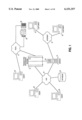
- FIG. 1 illustrates an embodiment of a transaction processing environment in which the present invention may be used.
- the transaction processing environment of FIG. 1 allows transaction initiators (e.g., customers) to contact an agent (e.g., a customer service agent) using various types of transactions.
- the transaction processing environment allows an agent to respond to a received transaction (e.g., received from a customer) or initiate a new transaction.
- a transaction processing system 10 is coupled to a server 12, a public switched telephone network (PSTN) 14 and a local area network (LAN) 16.
- Transaction processing system 10 is capable of processing various types of transactions, such as telephone calls, electronic mail (e-mail), voice mail, and facsimiles.
- Transaction processing system 10 is capable of receiving transactions from PSTN 14, LAN 16, and server 12.
- transaction processing system 10 is capable of transmitting transactions to PSTN 14, LAN16, and server 12.
- transaction processing system 10 can receive an incoming telephone call directly via PSTN 14.
- Another incoming telephone call may be received by server 12 (e.g., an Internet telephone call received across Internet 18) and provided to transaction processing system 10 across a communication link 34 or across LAN 16.
- transaction processing system 10 may receive an incoming e-mail from server 12 or LAN 16
- FIG. 1 illustrates a single server 12 capable of interacting with various components in the transaction processing environment.
- server 12 may operate as a web server, an e-mail server, a fax server, and a video server. Additionally, server 12 can perform the functions of a control server, as discussed below.
- the transaction processing environment may include multiple servers, in which each server is responsible for one or more types of transactions. For example, a web server processes all web-based transactions, an e-mail/fax server processes all e-mail and facsimile transactions, and a control server controls and manages various transactions and communication sessions in the transaction processing environment.
- LAN 16 can be any type of network, including an intranet network, capable of communicating information between various nodes in the network. Further, LAN 16 may use any network topology and communicate data using any communication protocol. As shown in FIG. 1, multiple agents 20 are coupled to LAN 16. In a typical transaction processing environment, hundreds or thousands of agents may be coupled to one or more LANs 16, which are coupled to transaction processing system 10. Alternatively, some or all of the agents 20 may be coupled directly to transaction processing system 10, rather than coupled through LAN 16. Although agents 20 are represented in FIG. 1 by a computer, a particular agent 20 may utilize any type of device or system that allows interaction between the agent and another person or device (such as a customer or a customer's computer).
- an agent handling only telephone call transactions may only use a telephone system, without requiring a computer.
- an agent handling only e-mail messages may require a computer system, but not a telephone.
- each agent has a computer system and a telephone (which may be integrated into the computer system), such that the agent is capable of handling and responding to multiple types of transactions (e.g., telephone calls, e-mail, voice mail, and facsimiles).
- Agent 32 is not coupled to LAN 16, but instead is coupled to PSTN 14. Agents 20, discussed above, are located locally to transaction processing system 10 or include an access mechanism allowing agents 20 to establish a connection to LAN 16. Agent 32 is a remote agent or otherwise unable to directly connect to LAN 16. For example, agent 32 may be working at a location geographically distant from transaction processing system 10, such as working at home or traveling. Agent 32 establishes a connection with transaction processing system 10 across PSTN 14. Alternatively, agent 32 may connect with LAN 16 or transaction processing system 10 through Internet 18 or any other network or communication system.
- a database 30 is coupled to LAN 16 and is used by transaction processing system 10, agents 20 and 32, and server 12 to store and retrieve various types of information.
- database 30 may contain information about the transaction processing system, the performance of the system, and the agents and customers that use transaction processing system 10. Since database 30 is coupled to LAN 16, all agent computers, servers, and other devices coupled to LAN 16 are capable of storing and retrieving information from the database.
- Internet 18 is coupled to server 12 and customer computers 22 and 24.
- Customer computer 22 may include an Internet phone for establishing verbal communications between the customer and an agent across Internet 18.
- the customer using computer 24 has a telephone 28 and a fax machine 26 coupled to PSTN 14 and located near computer 24.
- the user of computer 24 may communicate with an agent of the transaction processing system using Internet 18 (e.g., using an Internet phone or e-mail application), fax machine 26, telephone 28, or any combination thereof.
- customer 24 may generate and transmit an e-mail message across Internet 18 to server 12.
- Server 12 then communicates the e-mail to transaction processing system 10, which provides the e-mail to a particular agent or group of agents for response.
- Agents may be grouped together based on area of expertise, company department, or type of support provided (e.g., sales or technical support).
- the agent responding to the e-mail can respond with another e-mail message or may respond by telephone, facsimile, or any other type of transaction supported by the transaction processing system and the transaction initiator.
- the transaction initiator may specify the type of transaction used by the responding agent. For example, a transaction initiator may generate an e-mail transaction, but request that an agent respond with a telephone call.
- customer computers 22 and 24 are shown coupled directly to Internet 18, it will be appreciated that any communication mechanism can be used to couple computers 22 and 24 to Internet 18, such as PSTN 14 and an Internet Service Provider (ISP).
- ISP Internet Service Provider
- Internet 18 may be replaced with any communication network using any communication protocol.
- the environment illustrated in FIG. 1 includes a separate LAN 16 and Internet 18.
- LAN 16 and Internet 18 are merged into a single communication network capable of communicating information between any two or more devices coupled to the communication network.
- FIG. 2 illustrates an embodiment of a transaction processing environment including a server 40, an agent computer system 50, a customer computer system 52, and a transaction processing system 42 coupled together using various networks.
- FIG. 2 illustrates a single agent computer system 50 and a single customer computer system 52.
- a typical transaction processing environment includes multiple agent computer systems and multiple customer computer systems.
- Server 40 is coupled to Internet 44, a LAN 46, and transaction processing system 42.
- Server 40 includes a database management server 60, an application server 62, a control server 64, and a web server 66. Additional details regarding server 40 are discussed below.
- server 40, computer systems 50 and 52, and transaction processing system 42 are coupled together using different network configurations and network connections.
- Transaction processing system 42 is capable of processing various types of transactions, such as telephone calls, e-mail, voice mail, and facsimiles.
- transaction processing system 42 is an automatic call distributor (ACD).
- ATM automatic call distributor
- Agent computer system 50 includes an agent application 70, a browser application 72, and a telephony application 74.
- Agent application 70 interacts with other devices shown in FIG. 2 (e.g., server 40 and transaction processing system 42). For example, agent application 70 may retrieve information about a transaction initiator (such as account information and the types of products or services purchased) and display that information to the agent.
- agent application 70 is a client of database management server 60, which retrieves the appropriate information about the transaction initiator from a database 58. If the agent is a technical support agent, the information about the transaction initiator may include the types of products owned by the transaction initiator, previous problems encountered by the transaction initiator, and known problems with the products. Additionally, agent application 70 can display information regarding agent performance, the overall performance of the transaction processing system, and the current status of the agent (e.g., active or inactive).
- Browser application 72 is any browser capable of communicating information across a communication link and displaying received information to the agent.
- browser application 72 is capable of retrieving information from Internet 44 (e.g., in the form of Hypertext Markup Language (HTML) pages).
- Exemplary browser applications include Netscape CommunicatorTM sold by Netscape Communications Corporation of Mountain View, Calif., and Internet ExplorerTM sold by Microsoft Corporation of Redmond, Wash.
- Embodiments of the invention exchange information between agent application 70 and browser application 72.
- agent application 70 and browser application 72 are integrated into a single application.
- Telephony application 74 controls a telephone 54 coupled to agent computer system 50 and transaction processing system 42.
- a telephone adapter replaces telephone 54 and permits agent computer system 50 to perform the functions of a conventional telephone.
- a WinSetTM adapter sold by Aspect Telecommunications of San Jose, Calif., may be used instead of telephone 54.
- Another embodiment of the invention uses a software-based telephone in place of telephone 54.
- the software-based telephone is integrated into telephony application 74 and communicates with transaction processing system 42 through server 40 or LAN 46.
- Customer computer system 52 includes a client application 76, a browser application 78, and an Internet phone application 80.
- Client application 76 may be any type of application capable of being executed by customer computer system 52.
- client application 76 can be a word processor from which text is copied to browser application 78.
- FIG. 2 illustrates client application 76 and browser application 78 coupled to one another, in alternate embodiments of the invention there is no direct coupling of client application 76 and browser application 78.
- Browser application 78 is any browser capable of communicating information across a communication link and displaying received information to the customer.
- Browser application 78 is not necessarily the same type of browser application used in agent computer system 50.
- browser application 72 is capable of retrieving information from Internet 44 (e.g., in the form of Hypertext Markup Language (HTML) pages).
- Exemplary browser applications include Netscape CommunicatorTM and Internet ExplorerTM, identified above. Embodiments of the present invention can be implemented without any interaction between browser application 78 and other applications executed by customer computer system 52.
- Internet phone application 80 allows the user of computer system 52 to establish a voice communication link across Internet 44 instead of using a telephone 56 and a PSTN 48.
- customer computer system 52 does not contain an Internet phone application.
- the user of computer system 52 uses telephone 56 and PSTN 48 to establish a voice communication link with another individual or system.
- the user of computer system 52 may use a text chat window, discussed below with respect to FIG. 6, to communicate with another individual or system.
- Database management server 60 (contained in server 40) manages information contained in database 58.
- the information stored in database 58 includes customer information, product or service information, transaction tracking information, and other data that may be used by transaction processing system 42, agents, customers, or server 40.
- Application server 62 communicates with database management server 60 and provides information to agent application 70.
- application server 62 can retrieve information about a customer from database 58 using database management server 60. The retrieved information is then provided to agent application 70 across LAN 46 for display on agent computer system 50.
- Control server 64 performs multiple control and management functions, as discussed in greater detail below with respect to FIG. 3. Control server 64 establishes and maintains communication links between multiple pairs of agents and customers. Control server 64 communicates with transaction processing system 42 to locate one or more available agents, establishes data and/or voice connections between agents and customers, and controls the flow of data between agents and customers.
- Web server 66 communicates data, in the form of web pages, to browser applications 72 and 78. Additionally, web server 66 stores web pages and other web-based information used by the devices in the transaction processing environment. Web server 66 includes a filter service 68 that filters and modifies various web pages. Filter service 68 changes the web page content (e.g., by adding JavaScript methods) to allow the coordination and exchange of information between browser applications 72 and 78. For example, if a customer using browser application 78 changes information on a web page by entering information on a form, the information entered by the customer may be communicated to the agent's browser application 72. Similarly, if an agent selects a different web page using browser application 72, the selected web page may be delivered to browser application 78 for viewing by the customer.
- Filter service 68 changes the web page content (e.g., by adding JavaScript methods) to allow the coordination and exchange of information between browser applications 72 and 78. For example, if a customer using browser application 78 changes information on a web page by entering information on
- filter service 68 allows other services, discussed below, to coordinate web pages and web page information between browser applications 72 and 78 such that the agent and the customer view the same web page with the same information. Additional details regarding the various services that coordinate and exchange information between the browser applications are provided below with respect to FIGS. 3 and 4.
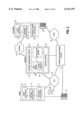
- FIG. 3 illustrates an embodiment of control server 64, shown as part of server 40 in FIG. 2.
- Control server 64 is shown coupled to an e-mail server 90, a fax server 92, a video server 94, and transaction processing system 42.
- E-mail server 90 handles both incoming e-mail (e.g., from a customer) and outgoing e-mail (e.g., from an agent).
- Fax server 92 handles both incoming and outgoing facsimiles.
- Video server 94 handles video information and video sessions, for use by an agent, customer, or other device or user in the transaction processing environment. Additionally, video server 94 handles other multimedia information and multimedia sessions (e.g., sessions that exchange both audio and video data).
- Transaction processing system 42 handles various transactions, as discussed above.
- E-mail server 90, fax server 92, and video server 94 may be coupled directly to control server 64 (and server 40 shown in FIG. 2) or coupled to control server 64 through a network (e.g., LAN 46) or other communication medium.
- a network e.g., LAN 46
- any one or more of servers 90 -94 can be contained within server 40 (FIG. 2) and coupled directly to control server 64.
- Control server 64 communicates with e-mail server 90, fax server 92, and video server 94 using any type of communication medium, such as LAN 46.
- control server 64 communicates with transaction processing system 42 using a dedicated communication line, as shown in FIG. 2.
- control server 64 communicates with transaction processing system 42 across a network, such as LAN 46 (FIG. 2).
- Control server 64 also communicates with other systems, such as browser applications and web servers, using a communication link 96.
- communication link 96 is a network communication link (e.g., a communication link in LAN 46).
- communication link 96 may be a dedicated communication link to one or more devices in the transaction processing environment. Communication link 96 is used to communicate various commands and other information between control server 64 and other devices.
- control server 64 includes an active script module 110 that handles the display of scripts and other information to an agent using the agent's browser application 72.
- An embodiment of active script module 110 generates scripts in the form of web pages that can be displayed on the agent's browser application. Additional details regarding agent scripts and other information displayed using an agent's browser application are provided below with respect to FIG. 6.
- a data logging and reporting module 112 controls the storage (or logging) of transaction information in database 58 using database management server 60. Additionally, module 112 is capable of generating various types of reports summarizing or identifying performance characteristics and other information related to the transaction processing environment. For example, module 112 may generate reports detailing the overall transaction handling performance, such as the number of transactions handled per hour, the average response time for each type of transaction, and the number of transaction responses that exceeded a quality of service limit for the transaction.
- a central control module 98 includes a transaction management interface 100, a transaction host 102, a synchronization service 104, a messaging service 106, and a server core 108.
- Server core 108 receives new requests (e.g., on communication link 96) from other devices in the transaction processing environment and provides the request to one or more other modules for processing. For example, server core 108 may continuously monitor communication link 96 for request signals that can be handled by server core 108. If the request signal is a request to generate a performance report, server core 108 forwards the request to data logging and reporting module 112 for processing. Module 112 then generates the requested report and provides the report to server core 108, which communicates the report to the appropriate device via communication link 96.
- server core 108 forwards the request to active script module 110, which selects or generates an appropriate agent script.
- Module 110 provides the agent script to server core 108, which then communicates the agent script to the appropriate device (e.g., the requesting device).
- Messaging service 106 establishes and manages message types used to communicate information between two or more individuals or devices in a transaction processing environment (e.g., message types used to communicate information between an agent and a customer). After a communication link has been established between, for example, an agent and a customer, messaging service 106 maintains the network or communication addresses for both the agent and customer. Typically, messaging service 106 establishes and manages multiple communication links for multiple customer-agent communications.
- Synchronization service 104 synchronizes changes between all participants in a particular communication. For example, in an agentcustomer communication, any changes entered to a web page by the customer are identified by synchronization service 104, and provided to the agent's browser application. Thus, synchronization service 104 ensures that all participants in a communication are provided with the same information.
- Transaction host 102 manages various portions of the interaction between, for example, an agent and a customer. Transaction host 102 maintains the status of multiple interactions and maintains the identity (such as the network or communication address) of each participant involved in each interaction. If a request is received to provide information to a participant, then transaction host 102 determines the address associated with the participant and provides the address to the appropriate module responsible for providing the requested information.
- Transaction management interface 100 is coupled to an e-mail transaction manager 114, a fax transaction manager 116, a video transaction manager 118, and a transaction processing system manager 120.
- Transaction management interface 100 manages the interaction and exchange of information between central control module 98 and the various transaction managers 114-120. Each transaction manager 114-120 handles a particular type of transaction, and communicates with the server responsible for that transaction type. In alternate embodiments of the invention, two or more of transaction managers 114-120 are combined into a single transaction manager.
- server core 108 receives a request that requires interaction with a server or device external to control server 64, then transaction management interface 100 contacts the appropriate transaction manager for processing the request. For example, if server core 108 receives a request to select an agent to handle a transaction, then transaction management interface 100 contacts transaction processing system manager 120 to request an agent from transaction processing system 42.
- Transaction management interface 100 may receive requests (or calls for service) from server core 108 or transaction host 102. Additionally, transaction management interface 100 may receive requests from any transaction manager 114-120. For example, e-mail transaction manager 114 may notify transaction management interface 100 that e-mail server 90 has received an e-mail that requires processing. Transaction management interface 100 then communicates the information regarding the received email to other services or managers to determine how the e-mail should be handled. For example, transaction processing system manager 120 may be contacted to identify an agent to handle the e-mail. The manner in which the e-mail is to be handled is then communicated to e-mail transaction manager 114, which then instructs e-mail server 90 regarding the processing of the e-mail.
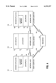
- FIG. 4 illustrates an embodiment of a system architecture for communicating information between various devices in a transaction processing environment.
- the system architecture of FIG. 4 includes a control server 130, an agent computer 132, and a customer computer 134.
- Agent computer 132 is coupled to control server 130 via communication link 138 (e.g., LAN 46 in FIG. 2) and coupled to a web server 136 via communication link 143 (e.g., Internet 44).
- Customer computer 134 is coupled to control server 130 using communication link 140 (e.g., Internet 44 in FIG. 2).
- Customer computer 134 is also coupled to web server 136 via communication link 142 (e.g., Internet 44).
- Web server 136 stores and distributes various web pages requested by a browser application. Although web server 136 and control server 130 are shown as two separate servers in FIG. 4, they may be hosted by the same hardware or the same server system.
- Agent computer 132 contains a browser application 144 of the type discussed above with respect to FIG. 2.
- the embodiment of the system architecture shown in FIG. 4 is implemented using the JavaTM programming language Java is a trademark of Sun Microsystems Inc. of Mountain View, Calif.). Alternate embodiments of the invention may be implemented using other programming languages, including object-oriented programming languages.
- Agent computer 132 contains one or more JavaScript methods 146 and one or more Java applets 148.
- a JavaScript method is a sequence of instructions that perform various operations and have the ability to invoke Java methods.
- a Java applet is a program, written in Java, that may be stored within a web page. When the web page is retrieved by a browser application, the Java applet is executed by the browser and performs the programmed operations.
- the activity or operation performed by the agent determines whether a JavaScript method or a Java applet is activated. For example, if the agent clicks an icon associated with a Java applet, then the Java applet is activated. However, if the agent performs an operation that is associated with a JavaScript method, then the JavaScript method is performed in response to the operation.
- Agent computer 132 includes a network layer 150, which is a logical layer at which agent computer 132 communicates with other devices via communication link 138.
- Control server 130 has a network layer 156, which communicates with control layer 150 to exchange information between control server 130 and agent computer 132.
- a Java server 154 communicates with network layer 156 to exchange information with other devices (e.g., agent computer 132 and customer computer 134).
- Java server 154 corresponds to server core 108 (FIG. 3) and controls the overall operation of control server 130.
- Java server 154 is implemented using the Java programming language.
- Java server 154 communicates with one or more Java servlets 152, which perform various operations necessary to process transactions and communicate information between devices.
- Java servlets 152 may correspond to various modules shown in FIG. 3, such as transaction management interface 100, transaction host 102, synchronization service 104, messaging service 106, active script module 110, and data logging and reporting module 112.
- a network layer 164 in customer computer 134 communicates with network layer 156 and with web server 136. Although not shown in FIG. 4, web server 136 may also include a network layer for communicating data across communication link 142.
- Customer computer 134 contains one or more Java applets 162 and one or more JavaScript methods 160. Additional details regarding the operation of Java applets 162 and JavaScript methods 160 are provided below.
- Customer computer 134 also includes a browser application 158 of the type discussed above with respect to FIG. 2.
- an agent is able to "push" a web page or other information to a customer using the system shown in FIG. 4.
- the agent may identify a particular web page and communicate the uniform resource locator (URL) associated with the web page to customer computer 134 via control server 130.
- the customer's browser application 158 receives the URL and retrieves the associated web page from web server 136.
- the agent "pushes" the web page to the customer by providing the URL associated with the web page to the customer's browser application.
- FIG. 5 is a flow diagram illustrating an embodiment of a procedure for communicating information between various devices using the architecture of FIG. 4.
- a customer contacts a web server (e.g., web server 136) and retrieves one or more web pages for viewing using a browser application (e.g., browser application 158).
- the customer requests additional information about a product or service, or requests to be contacted by an agent.
- the customer may specify the manner in which the information or agent contact is handled (e.g., by return telephone call, by e-mail, or by facsimile). If the customer requests to be contacted using a conventional telephone or by facsimile, then the customer is asked to provide a telephone number for initiating the telephone call or facsimile.
- a JavaScript method contained in the web page accessed by the customer, is executed by the customer's browser application.
- the JavaScript method causes the customer's computer to contact the Java server (e.g., Java server 154) and requests a Java applet and any necessary JavaScript methods.
- the requested Java applet and JavaScript methods are then communicated from the Java server to the customer's computer.
- the particular Java applet and JavaScript methods communicated to the customer's computer may vary depending on the web page that was being viewed by the customer when the request for additional information or agent contact was entered.
- the particular web page being viewed may contain JavaScript methods that identify the necessary Java applet and JavaScript methods to be communicated to the customer's computer.
- the Java applet (running on the customer's computer) contacts the Java server and communicates the customer's request to the Java server.
- the customer has requested that an agent contact the customer by return telephone call.
- Step 178 calls the transaction host servlet (e.g., the servlet that performs the functions of transaction host 102 in FIG. 3), which locates an agent to handle the customer's request.
- An agent may be located by communicating with transaction processing system manager 120 to select an agent and to initiate a telephone call across the PSTN.
- step 180 contacts the selected agent and informs the agent regarding the customer's request. At this time, information about the customer may be displayed to the selected agent (e.g., account information, or past purchases).
- Step 180 also establishes a communication link (in this example, a telephone link) between the selected agent and the customer.
- a transaction processing system may be used to automatically establish the telephone link across a PSTN or a web server may be used to establish an Internet telephone call across the Internet.
- both a voice communication link and a data communication link are established between the agent and the customer.
- the data communication link can be established and maintained by the control server. Both the agent computer and the customer computer may communicate with the control server, which coordinates the flow of messages and other information between the agent and the customer. For example, the control server forwards messages received from the agent computer system to the customer computer system, and vice versa.
- the Java server communicates any necessary setup information to the customer's computer and notifies the customer that the communication link has been established.
- This notification can be performed, for example, by communicating through the network layers to the customer's browser application.
- the customer requested a return telephone call.
- the customer and the agent may continue to communicate using their browser applications. For example, the agent may "push" web pages or other information to the customer for viewing using the customer's browser application.
- FIG. 6 illustrates an embodiment of various windows (also referred to as frames) displayed to an agent using the agent's computer.
- An agent's computer includes a display device that provides visual information to the agent.
- an agent's browser application generates a display 190 containing multiple frames 192,194, 196, 198, and 200.
- Frame 192 represents the web page or other information currently being displayed to the customer.
- the agent is able to easily determine what information is available to the customer based on frame 192.
- the agent can provide additional information about a product or service while referring to the information already displayed to the customer.
- Frame 194 is a text chat window that allows the agent and the customer to communicate using typed information.
- the text chat window can be used at any time, and is particularly useful when a voice connection cannot be established between the agent and the customer (e.g., the customer does not have an Internet phone and has only one telephone line, which is used to access the Internet).
- Frame 196 of display 190 contains various system information such as information about the agent and information relating to the overall system performance. Frame 196 may also be used to display messages to an agent from a supervisor or system administrator (e.g., asking the agent if they are available to work overtime, or notifying the agent of their next scheduled break).
- Frame 198 displays agent script information, such as a prepared script to be read to a customer. The script displayed in frame 198 may be modified to correspond to the product or service being discussed, or the script may be modified to include information about the customer (e.g., the customer's name).
- Frame 200 provides various links to information that may be provided by the agent to the customer. In a particular embodiment of the invention, the links shown in frame 200 are associated with web pages that contain information of interest to particular customers.
- the link "FAQ--Acme XL-3000" may identify a web page that contains answers to frequently asked questions about the Acme XL-3000 computer system. If the agent wants to display these answers to the customer, the agent can select the link, which causes the web page to be transmitted to the customer's browser application. The same web page is then displayed in frame 192, to maintain correspondence between frame 192 and the web page displayed to the customer.
- a visual indicator 202 is located near the middle of display 190, and indicates the status of a transmission to the agent.
- the appearance of visual indicator 202 may change based on the transmission status (e.g., indicating a complete transaction, an incomplete transaction, or a congested communication link).
- Various types of visual indicators 202 may be used to indicate transmission status and can be located anywhere on display 190. Other types of visual indicators are discussed below with respect to FIGS. 9A-9C.
- the visual indicator notifies the agent if a particular transmission (e.g., the transmission of a web page to a customer) has been completed or whether the communication link between the agent and the customer is congested.
- the agent is not able to determine the status of the transmission because the agent cannot see the customer's computer display showing the web page or other information being transmitted. Although the same information is also displayed in frame 192, the speed at which the information is displayed in frame 192 is not generally the speed at which the information is transmitted to the customer.
- visual indicator 202 can be used in any communication environment, and is not limited to a transaction processing environment. Furthermore, visual indicator 202 may be used with any transmission source and any transmission destination to communicate the transmission status to the transmission source (or initiator of the transmission). In the embodiments discussed, visual indicator 202 is displayed proximate the transmission source.
- the transmission source may be the actual system that initiates and controls the transmission of information to a transmission destination. Alternatively, the transmission source may be the system that causes another device (located local or remote to the transmission source) to transmit information to a transmission destination. Thus, any device involved in the transmission of information to a transmission destination can be a transmission source.
- visual indicator 202 can be displayed proximate the transmission source, but not on the transmission source itself. For example, visual indicator 202 may be displayed on a supervisor's computer system although the supervisor is not the transmission source.
- Particular embodiments of the invention display visual indicator 202 to the initiator of the transmission (e.g., the agent initiating the transmission of a web page or other information to a customer).
- the transmission initiator may be located proximate the transmission source or may be located distant from the transmission source (e.g., using a remote computer system to access the transmission source).
- Embodiments of the invention display visual indicator 202 on two or more computer systems or other devices.
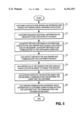
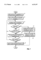
- FIG. 7 is a flow diagram illustrating an embodiment of a procedure for displaying visual indicators representing transmission status.
- the procedure described with respect to FIG. 7 refers to an agent initiating a data transmission to a customer. However, the procedure illustrated in FIG. 7 may be applied to any transmission between a source and a destination across any type of communication link.
- an agent initiates a data transmission to a customer across a communication link (e.g., transmitting a web page to the customer).
- Step 212 displays a visual indicator to the agent indicating that the data transmission is incomplete.
- the customer's computer begins to receive and process the data transmission. In the example of a web page, the customer's computer may begin to display the web page as it is received.
- Step 216 determines whether the transmission from the agent to the customer is complete. A procedure (e.g., a JavaScript method) executed by the customer's computer can be used to determine when the transmission is completed. If the transmission is complete, the procedure branches to step 218, where the customer's computer transmits a message to the agent's computer indicating that the data transmission is complete.
- the visual indicator displayed to the agent is changed to indicate that the data transmission is complete.
- step 222 determines whether the communication link is congested.
- Congested communication links can be identified by a small amount of received data for a particular period of time. The agent or the customer may specify particular thresholds for detecting a congested communication link (e.g., transmission rate below a transmission threshold rate for a particular time period). Alternatively, default thresholds may be provided for detecting communication link congestion. If step 222 does not identify congestion on the communication link, then the procedure returns to step 214 to continue receiving and processing data. If congestion is identified at step 222, then the procedure continues to step 224, which changes the visual indicator displayed to the agent to indicate a congested communication link.
- Step 226 determines whether the agent has terminated the data transmission. Step 226 may include advising the agent to terminate the transmission. If the agent does not terminate the transmission, then the procedure returns to step 214. If the agent terminates the transmission, then step 228 changes the visual indicator displayed to the agent to indicate an aborted transaction.
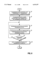
- FIG. 8 is a flow diagram illustrating an embodiment of a procedure for determining the status of a transmission across a communication link.
- a transmission source initiates a data transmission to a transmission destination across a communication link.
- the transmission source causes instructions to be transmitted to the transmission destination.
- the instructions allow the transmission destination to determine the transmission status and communicate that status back to the transmission source. If the transmission destination has already received the instructions (e.g., during a previous data transmission or as part of an initialization of the communication between the source and the destination), then step 242 can be disregarded.
- the instructions are in the form of a JavaScript method or a Java applet to be executed by the transmission destination. In alternate embodiments, any type of instruction using any procedural language can be communicated to the transmission destination.
- the transmission destination determines the transmission status (e.g., using the instructions communicated to the transmission destination in step 242). If the transmission destination knows the total size of the transmission, then it can determine the portion of the transmission that has been completed. However, if the transmission destination does not know the total size of the transmission, then the destination determines whether the transmission is complete and whether the communication link is congested. The transmission destination may determine that the transmission is complete when, for example, an end-of-file or end-of-transmission indicator is received. Both the transmission source and the transmission destination may communicate with a control server, such as control server 130 discussed above. In this situation, the control server coordinates the flow of data and other information between the transmission source and the transmission destination. Thus, the control server receives information from both the source and the destination and forwards the received information to the other data transmission participant, as necessary. Additionally, the control server is able to coordinate the flow of data and other information between multiple transmission sources and multiple transmission destinations.
- a control server such as control server 130 discussed above. In this situation, the control server coordinates the flow of
- the transmission destination communicates the transmission status to the transmission source. This transmission status is used by the transmission source to change, as necessary, the visual indicator displayed to the transmission initiator or displayed proximate the transmission source. In a particular embodiment of the invention, the transmission destination, in step 246, also communicates the amount of data received in the current data transmission. If the transmission source knows the total size of the data transmission, then the source uses the information regarding the amount of data received by the destination to determine the percentage of the transmission that has been completed.
- step 248 the procedure determines whether the data transmission is complete. If the transmission is not complete, the procedure returns to step 244 to determine (i.e., update) the transmission status. If the transmission status has not changed since the last determination, then step 246 may be disregarded. If step 248 determines that the transmission is complete, the procedure continues to step 250, where the transmission source is notified that the transmission is complete.
- embodiments of the invention provide instructions from the transmission source to the transmission destination for communicating the transmission status back to the transmission source. Since these instructions are provided by the transmission source, the transmission destination does not require any additional hardware or software programs to implement the invention (as long as the transmission destination is able to execute the received instructions).
- the instructions are written in the Java programming language.
- any browser application that supports Java and JavaScript methods can execute the Java and JavaScript instructions.
- the invention may be used with a variety of transmission destinations without requiring the destination to have specialized hardware or software to execute the instructions.
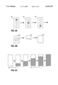
- FIGS. 9A-9C illustrate examples of visual indicators that represent transmission status.
- FIG. 9A illustrates three different versions of visual indicator 202 (also shown in FIG. 6).
- the top circle is highlighted (or filled), indicating that the data transmission has not yet started.
- the middle circle is highlighted (or filled), indicating that the data transmission has started, but is incomplete.
- visual indicator 202 changes to the third version, in which the bottom circle is highlighted (or filled).
- the three circles in visual indicator 202 when highlighted, may be different colors.
- the top circle is red
- the middle circle is yellow
- the bottom circle is green (i.e., colors commonly used in a traffic light).
- Various changes can be made to visual indicator 202 to indicate a congested link, such as causing one or more of the circles to flash, highlighting two or more circles simultaneously, changing the color of the highlighted circle, or changing the color of the entire visual indicator.
- visual indicator 202 the operator of the computer or device displaying visual indicator 202 is able to quickly determine the status of the transmission. For example, an agent may be waiting for a web page to be transmitted to a customer before discussing various details contained in the web page. Visual indicator 202 notifies the agent when the entire web page has been received by the customer and, therefore, displayed on the customer's computer. Additionally, visual indicator 202 alerts the agent to potential communication link congestion and allows the agent to terminate the transmission or attempt to retransmit the web page.
- FIG. 9B illustrates another embodiment of a visual indicator 202 that represents the status of a data transmission.
- the first version of the visual indicator 202 represents the status when the transmission has not been started.
- the second version identifies that the transmission has started, but is not yet complete.
- the third version of the visual indicator 202 is displayed.
- FIG. 9C illustrates a visual indicator 202 having six different versions, representing varying stages of data transmission status.
- FIGS. 9A-9C represent examples of visual indicators 202 that represent transmission status.
- the teachings of the present invention can be used with various other types of visual indicators 202 to represent transmission status.
- FIG. 10 illustrates an embodiment of a computer system that can be used with the present invention.
- embodiments of the invention may use a computer of the type shown in FIG. 10 for an agent's computer, a customer's computer, a server, a transaction processing system, or any other device contained in or used with the transaction processing environment discussed above.
- the various components in FIG. 10 are provided by way of example. Certain components of the computer in FIG. 10 can be deleted for particular implementations of the invention.
- the computer system shown in FIG. 10 may be any type of computer, including a general purpose computer.
- FIG. 10 illustrates a system bus 300 to which various components and devices are coupled.
- a processor 302 performs the processing tasks required by the computer.
- Processor 302 may be any type of processing device capable of implementing the steps necessary to perform the various procedures and operations discussed above.
- An Input/Output (I/O) device 304 is coupled to bus 300 and provides a mechanism for communicating with other devices coupled to the computer.
- a Read-Only Memory (ROM) 306 and a Random Access Memory (RAM) 308 are coupled to bus 300 and provide a storage mechanism for various data and information used by the computer.
- ROM 306 and RAM 308 are shown coupled to bus 300, in alternate embodiments, ROM 306 and RAM 308 are coupled directly to processor 302 or coupled to a dedicated memory bus (not shown).
- a video display 310 is coupled to bus 300 and displays various information and data to the user of the computer.
- a disk drive 312 is coupled to bus 300 and provides a mechanism for the long-term mass storage of information.
- An input device 314 and a pointing device 316 are also coupled to bus 300 and allow the user of the computer to enter information and commands to the computer system.
- Input device 314 may be, for example, a keyboard, keypad, handwriting recognition device, or voice recognition device.
- Pointing device 316 includes, for example, a mouse, track ball, or touch pad.
- a printer 318 is coupled to bus 300 and is capable of creating a hard copy of information generated by or used by the computer.
- Embodiments of the present invention may be implemented using a computer-readable medium (also referred to as a processor-readable medium) containing various sets of instructions, code sequences, configuration information, and other data used by a computer or other processing device.
- the various information stored on the computerreadable medium is used to perform various data communication, data processing, and data handling operations, such as those described above.
- the computer-readable medium may be any type of magnetic, optical, or electrical storage medium including a diskette, magnetic tape, CD-ROM, memory device, or other storage medium.
Abstract
Description
Claims (30)
Priority Applications (1)
| Application Number | Priority Date | Filing Date | Title |
|---|---|---|---|
| US09/008,956 US6151357A (en) | 1998-01-16 | 1998-01-16 | Method and apparatus for displaying a visual indication of a transmission status |
Applications Claiming Priority (1)
| Application Number | Priority Date | Filing Date | Title |
|---|---|---|---|
| US09/008,956 US6151357A (en) | 1998-01-16 | 1998-01-16 | Method and apparatus for displaying a visual indication of a transmission status |
Publications (1)
| Publication Number | Publication Date |
|---|---|
| US6151357A true US6151357A (en) | 2000-11-21 |
Family
ID=21734686
Family Applications (1)
| Application Number | Title | Priority Date | Filing Date |
|---|---|---|---|
| US09/008,956 Expired - Lifetime US6151357A (en) | 1998-01-16 | 1998-01-16 | Method and apparatus for displaying a visual indication of a transmission status |
Country Status (1)
| Country | Link |
|---|---|
| US (1) | US6151357A (en) |
Cited By (29)
| Publication number | Priority date | Publication date | Assignee | Title |
|---|---|---|---|---|
| US20010018713A1 (en) * | 2000-02-14 | 2001-08-30 | Takeshi Kokado | Data transmission system |
| US20010021948A1 (en) * | 1997-08-29 | 2001-09-13 | Khouri Joseph F. | Method and apparatus for processing a telephone call |
| US6430597B1 (en) * | 1998-01-16 | 2002-08-06 | Aspect Communications Corporation | Method and apparatus for generating agent scripts |
| US6480581B1 (en) * | 1999-06-22 | 2002-11-12 | Institute For Information Industry | Internet/telephone adapter device and method |
| US6499036B1 (en) * | 1998-08-12 | 2002-12-24 | Bank Of America Corporation | Method and apparatus for data item movement between disparate sources and hierarchical, object-oriented representation |
| US20030060624A1 (en) * | 2001-04-20 | 2003-03-27 | Singer Robert A. | Process for the preparation of 1,3-substituted indenes and aryl-fused azapolycyclic componunds |
| US20030217283A1 (en) * | 2002-05-20 | 2003-11-20 | Scott Hrastar | Method and system for encrypted network management and intrusion detection |
| US20030219008A1 (en) * | 2002-05-20 | 2003-11-27 | Scott Hrastar | System and method for wireless lan dynamic channel change with honeypot trap |
| US20030233567A1 (en) * | 2002-05-20 | 2003-12-18 | Lynn Michael T. | Method and system for actively defending a wireless LAN against attacks |
| US20030236990A1 (en) * | 2002-05-20 | 2003-12-25 | Scott Hrastar | Systems and methods for network security |
| US20040008652A1 (en) * | 2002-05-20 | 2004-01-15 | Tanzella Fred C. | System and method for sensing wireless LAN activity |
| US20040030797A1 (en) * | 2002-08-12 | 2004-02-12 | Cuneyt Akinlar | Quality of service management in network gateways |
| US6751211B1 (en) | 1998-04-03 | 2004-06-15 | Aspect Communications Corporation | Method and apparatus for communicating information |
| US20040203764A1 (en) * | 2002-06-03 | 2004-10-14 | Scott Hrastar | Methods and systems for identifying nodes and mapping their locations |
| US6882450B1 (en) * | 1998-11-24 | 2005-04-19 | Ricoh Company, Ltd. | Facsimile device and a facsimile device monitoring system |
| US20050174961A1 (en) * | 2004-02-06 | 2005-08-11 | Hrastar Scott E. | Systems and methods for adaptive monitoring with bandwidth constraints |
| US20050196154A1 (en) * | 2004-03-08 | 2005-09-08 | Tatung Co., Ltd. | Portable DVD player with a USB transmission interface |
| US6993569B1 (en) * | 1999-11-01 | 2006-01-31 | Ita Software, Inc. | Transmitting information over a network |
| US7322044B2 (en) | 2002-06-03 | 2008-01-22 | Airdefense, Inc. | Systems and methods for automated network policy exception detection and correction |
| US7324804B2 (en) | 2003-04-21 | 2008-01-29 | Airdefense, Inc. | Systems and methods for dynamic sensor discovery and selection |
| US7359676B2 (en) | 2003-04-21 | 2008-04-15 | Airdefense, Inc. | Systems and methods for adaptively scanning for wireless communications |
| US7522908B2 (en) | 2003-04-21 | 2009-04-21 | Airdefense, Inc. | Systems and methods for wireless network site survey |
| US7532895B2 (en) | 2002-05-20 | 2009-05-12 | Air Defense, Inc. | Systems and methods for adaptive location tracking |
| US7577424B2 (en) | 2005-12-19 | 2009-08-18 | Airdefense, Inc. | Systems and methods for wireless vulnerability analysis |
| US7715800B2 (en) | 2006-01-13 | 2010-05-11 | Airdefense, Inc. | Systems and methods for wireless intrusion detection using spectral analysis |
| US7970013B2 (en) | 2006-06-16 | 2011-06-28 | Airdefense, Inc. | Systems and methods for wireless network content filtering |
| US7971251B2 (en) | 2006-03-17 | 2011-06-28 | Airdefense, Inc. | Systems and methods for wireless security using distributed collaboration of wireless clients |
| US8196199B2 (en) | 2004-10-19 | 2012-06-05 | Airdefense, Inc. | Personal wireless monitoring agent |
| US8281392B2 (en) | 2006-08-11 | 2012-10-02 | Airdefense, Inc. | Methods and systems for wired equivalent privacy and Wi-Fi protected access protection |
Citations (20)
| Publication number | Priority date | Publication date | Assignee | Title |
|---|---|---|---|---|
| US1678973A (en) * | 1926-01-25 | 1928-07-31 | Rca Corp | Signal-monitoring system |
| US4064459A (en) * | 1975-07-09 | 1977-12-20 | Siemens Aktiengesellschaft | Method of automatically testing the serviceability of a data transmission system |
| US4398299A (en) * | 1980-10-10 | 1983-08-09 | Bell Telephone Laboratories, Incorporated | Data set network diagnostic system |
| US4398297A (en) * | 1980-10-10 | 1983-08-09 | Bell Telephone Laboratories, Incorporated | Data set diagnostic system |
| US4728925A (en) * | 1985-07-03 | 1988-03-01 | Tektronix, Inc. | Data communications analyzer |
| US4766536A (en) * | 1984-04-19 | 1988-08-23 | Rational | Computer bus apparatus with distributed arbitration |
| US4885779A (en) * | 1987-11-02 | 1989-12-05 | Atalla Corporation | Personal identification encryptor system with error-correcting code and method |
| US4920533A (en) * | 1987-11-02 | 1990-04-24 | Videotron Ltee | CATV subscriber terminal transmission control |
| US5255086A (en) * | 1990-03-20 | 1993-10-19 | Scientific-Atlanta, Inc. | Method and apparatus for RF data transfer in a CATV system |
| US5291489A (en) * | 1987-11-13 | 1994-03-01 | Dsc Communications Corporation | Interprocessor switching network |
| US5305405A (en) * | 1993-02-25 | 1994-04-19 | Adc Telecommunications, Inc. | Patch cord |
| US5343509A (en) * | 1991-08-30 | 1994-08-30 | Dounies Gregory F | Emergency information facsimile transmitter |
| US5727002A (en) * | 1995-01-19 | 1998-03-10 | Starburst Communications Corporation | Methods for transmitting data |
| US5745836A (en) * | 1995-09-01 | 1998-04-28 | Cable Television Laboratories, Inc. | Undesirable energy suppression system in a contention based communication network |
| US5764371A (en) * | 1994-12-19 | 1998-06-09 | Ricoh Company, Ltd. | Image forming apparatus for indicating completion of scanning for both sides of an orginal document |
| US5793499A (en) * | 1996-10-11 | 1998-08-11 | Hewlett-Packard Company | Fax status stamp on back of document |
| US5887050A (en) * | 1997-05-09 | 1999-03-23 | Siemens Building Technologies, Inc. | Repeater apparatus having isolation circuit |
| US5894595A (en) * | 1994-08-01 | 1999-04-13 | At&T Corp | Personal mobile communication system |
| US5936743A (en) * | 1995-12-22 | 1999-08-10 | Ricoh Company, Ltd. | Facsimile control system |
| US5956154A (en) * | 1994-09-22 | 1999-09-21 | Matthew J. Cairo | Certified facsimile |
-
1998
- 1998-01-16 US US09/008,956 patent/US6151357A/en not_active Expired - Lifetime
Patent Citations (20)
| Publication number | Priority date | Publication date | Assignee | Title |
|---|---|---|---|---|
| US1678973A (en) * | 1926-01-25 | 1928-07-31 | Rca Corp | Signal-monitoring system |
| US4064459A (en) * | 1975-07-09 | 1977-12-20 | Siemens Aktiengesellschaft | Method of automatically testing the serviceability of a data transmission system |
| US4398299A (en) * | 1980-10-10 | 1983-08-09 | Bell Telephone Laboratories, Incorporated | Data set network diagnostic system |
| US4398297A (en) * | 1980-10-10 | 1983-08-09 | Bell Telephone Laboratories, Incorporated | Data set diagnostic system |
| US4766536A (en) * | 1984-04-19 | 1988-08-23 | Rational | Computer bus apparatus with distributed arbitration |
| US4728925A (en) * | 1985-07-03 | 1988-03-01 | Tektronix, Inc. | Data communications analyzer |
| US4885779A (en) * | 1987-11-02 | 1989-12-05 | Atalla Corporation | Personal identification encryptor system with error-correcting code and method |
| US4920533A (en) * | 1987-11-02 | 1990-04-24 | Videotron Ltee | CATV subscriber terminal transmission control |
| US5291489A (en) * | 1987-11-13 | 1994-03-01 | Dsc Communications Corporation | Interprocessor switching network |
| US5255086A (en) * | 1990-03-20 | 1993-10-19 | Scientific-Atlanta, Inc. | Method and apparatus for RF data transfer in a CATV system |
| US5343509A (en) * | 1991-08-30 | 1994-08-30 | Dounies Gregory F | Emergency information facsimile transmitter |
| US5305405A (en) * | 1993-02-25 | 1994-04-19 | Adc Telecommunications, Inc. | Patch cord |
| US5894595A (en) * | 1994-08-01 | 1999-04-13 | At&T Corp | Personal mobile communication system |
| US5956154A (en) * | 1994-09-22 | 1999-09-21 | Matthew J. Cairo | Certified facsimile |
| US5764371A (en) * | 1994-12-19 | 1998-06-09 | Ricoh Company, Ltd. | Image forming apparatus for indicating completion of scanning for both sides of an orginal document |
| US5727002A (en) * | 1995-01-19 | 1998-03-10 | Starburst Communications Corporation | Methods for transmitting data |
| US5745836A (en) * | 1995-09-01 | 1998-04-28 | Cable Television Laboratories, Inc. | Undesirable energy suppression system in a contention based communication network |
| US5936743A (en) * | 1995-12-22 | 1999-08-10 | Ricoh Company, Ltd. | Facsimile control system |
| US5793499A (en) * | 1996-10-11 | 1998-08-11 | Hewlett-Packard Company | Fax status stamp on back of document |
| US5887050A (en) * | 1997-05-09 | 1999-03-23 | Siemens Building Technologies, Inc. | Repeater apparatus having isolation circuit |
Cited By (50)
| Publication number | Priority date | Publication date | Assignee | Title |
|---|---|---|---|---|
| US6678718B1 (en) | 1997-08-29 | 2004-01-13 | Aspect Communications Corporation | Method and apparatus for establishing connections |
| US20010021948A1 (en) * | 1997-08-29 | 2001-09-13 | Khouri Joseph F. | Method and apparatus for processing a telephone call |
| US6871212B2 (en) | 1997-08-29 | 2005-03-22 | Aspect Communication Corporation | Method and apparatus for processing a telephone call |
| US20030069937A1 (en) * | 1997-08-29 | 2003-04-10 | Khouri Joseph F. | Method and apparatus for establishing connections |
| US6430597B1 (en) * | 1998-01-16 | 2002-08-06 | Aspect Communications Corporation | Method and apparatus for generating agent scripts |
| US6751211B1 (en) | 1998-04-03 | 2004-06-15 | Aspect Communications Corporation | Method and apparatus for communicating information |
| US6499036B1 (en) * | 1998-08-12 | 2002-12-24 | Bank Of America Corporation | Method and apparatus for data item movement between disparate sources and hierarchical, object-oriented representation |
| US20030120600A1 (en) * | 1998-08-12 | 2003-06-26 | Gurevich Michael N. | Method and apparatus for data item movement between disparate sources and hierarchical, object-oriented representation |
| US7917538B2 (en) | 1998-08-12 | 2011-03-29 | Bank Of America Corporation | Method and apparatus for data item movement between disparate sources and hierarchical, object-oriented representation |
| US7111016B2 (en) | 1998-08-12 | 2006-09-19 | Bank Of America Corporation | Method and apparatus for data item movement between disparate sources and hierarchical, object-oriented representation |
| US20070011194A1 (en) * | 1998-08-12 | 2007-01-11 | Bank Of America Corporation | Method and apparatus for data item movement between disparate sources and hierarchical, object-oriented representation |
| US20070081198A1 (en) * | 1998-11-24 | 2007-04-12 | Ricoh Company, Ltd. | Facsimile device and a facsimile device monitoring system |
| US7170646B2 (en) | 1998-11-24 | 2007-01-30 | Ricoh Company, Ltd. | Facsimile device and a facsimile device monitoring system |
| US7369281B2 (en) | 1998-11-24 | 2008-05-06 | Ricoh Company, Ltd. | Facsimile device and a facsimile device monitoring system |
| US6882450B1 (en) * | 1998-11-24 | 2005-04-19 | Ricoh Company, Ltd. | Facsimile device and a facsimile device monitoring system |
| US6480581B1 (en) * | 1999-06-22 | 2002-11-12 | Institute For Information Industry | Internet/telephone adapter device and method |
| US6993569B1 (en) * | 1999-11-01 | 2006-01-31 | Ita Software, Inc. | Transmitting information over a network |
| US7093026B2 (en) * | 2000-02-14 | 2006-08-15 | Matsushita Electric Industrial, Co. Ltd | Data transmission system |
| US20010018713A1 (en) * | 2000-02-14 | 2001-08-30 | Takeshi Kokado | Data transmission system |
| US20030060624A1 (en) * | 2001-04-20 | 2003-03-27 | Singer Robert A. | Process for the preparation of 1,3-substituted indenes and aryl-fused azapolycyclic componunds |
| US7058796B2 (en) | 2002-05-20 | 2006-06-06 | Airdefense, Inc. | Method and system for actively defending a wireless LAN against attacks |
| US20030219008A1 (en) * | 2002-05-20 | 2003-11-27 | Scott Hrastar | System and method for wireless lan dynamic channel change with honeypot trap |
| US7042852B2 (en) | 2002-05-20 | 2006-05-09 | Airdefense, Inc. | System and method for wireless LAN dynamic channel change with honeypot trap |
| US8060939B2 (en) | 2002-05-20 | 2011-11-15 | Airdefense, Inc. | Method and system for securing wireless local area networks |
| US7086089B2 (en) | 2002-05-20 | 2006-08-01 | Airdefense, Inc. | Systems and methods for network security |
| US20030217283A1 (en) * | 2002-05-20 | 2003-11-20 | Scott Hrastar | Method and system for encrypted network management and intrusion detection |
| US7779476B2 (en) | 2002-05-20 | 2010-08-17 | Airdefense, Inc. | Active defense against wireless intruders |
| US20040008652A1 (en) * | 2002-05-20 | 2004-01-15 | Tanzella Fred C. | System and method for sensing wireless LAN activity |
| US20030236990A1 (en) * | 2002-05-20 | 2003-12-25 | Scott Hrastar | Systems and methods for network security |
| US20030233567A1 (en) * | 2002-05-20 | 2003-12-18 | Lynn Michael T. | Method and system for actively defending a wireless LAN against attacks |
| US7277404B2 (en) | 2002-05-20 | 2007-10-02 | Airdefense, Inc. | System and method for sensing wireless LAN activity |
| US7532895B2 (en) | 2002-05-20 | 2009-05-12 | Air Defense, Inc. | Systems and methods for adaptive location tracking |
| US7526808B2 (en) | 2002-05-20 | 2009-04-28 | Airdefense, Inc. | Method and system for actively defending a wireless LAN against attacks |
| US7383577B2 (en) | 2002-05-20 | 2008-06-03 | Airdefense, Inc. | Method and system for encrypted network management and intrusion detection |
| US7322044B2 (en) | 2002-06-03 | 2008-01-22 | Airdefense, Inc. | Systems and methods for automated network policy exception detection and correction |
| US20040203764A1 (en) * | 2002-06-03 | 2004-10-14 | Scott Hrastar | Methods and systems for identifying nodes and mapping their locations |
| US7802008B2 (en) * | 2002-08-12 | 2010-09-21 | Matsushita Electric Industrial Co., Ltd. | Quality of service management in network gateways |
| US20040030797A1 (en) * | 2002-08-12 | 2004-02-12 | Cuneyt Akinlar | Quality of service management in network gateways |
| US7324804B2 (en) | 2003-04-21 | 2008-01-29 | Airdefense, Inc. | Systems and methods for dynamic sensor discovery and selection |
| US7359676B2 (en) | 2003-04-21 | 2008-04-15 | Airdefense, Inc. | Systems and methods for adaptively scanning for wireless communications |
| US7522908B2 (en) | 2003-04-21 | 2009-04-21 | Airdefense, Inc. | Systems and methods for wireless network site survey |
| US7355996B2 (en) | 2004-02-06 | 2008-04-08 | Airdefense, Inc. | Systems and methods for adaptive monitoring with bandwidth constraints |
| US20050174961A1 (en) * | 2004-02-06 | 2005-08-11 | Hrastar Scott E. | Systems and methods for adaptive monitoring with bandwidth constraints |
| US20050196154A1 (en) * | 2004-03-08 | 2005-09-08 | Tatung Co., Ltd. | Portable DVD player with a USB transmission interface |
| US8196199B2 (en) | 2004-10-19 | 2012-06-05 | Airdefense, Inc. | Personal wireless monitoring agent |
| US7577424B2 (en) | 2005-12-19 | 2009-08-18 | Airdefense, Inc. | Systems and methods for wireless vulnerability analysis |
| US7715800B2 (en) | 2006-01-13 | 2010-05-11 | Airdefense, Inc. | Systems and methods for wireless intrusion detection using spectral analysis |
| US7971251B2 (en) | 2006-03-17 | 2011-06-28 | Airdefense, Inc. | Systems and methods for wireless security using distributed collaboration of wireless clients |
| US7970013B2 (en) | 2006-06-16 | 2011-06-28 | Airdefense, Inc. | Systems and methods for wireless network content filtering |
| US8281392B2 (en) | 2006-08-11 | 2012-10-02 | Airdefense, Inc. | Methods and systems for wired equivalent privacy and Wi-Fi protected access protection |
Similar Documents
| Publication | Publication Date | Title |
|---|---|---|
| US6151357A (en) | Method and apparatus for displaying a visual indication of a transmission status | |
| US6094673A (en) | Method and apparatus for generating agent scripts | |
| US6256620B1 (en) | Method and apparatus for monitoring information access | |
| US6657990B1 (en) | Method and apparatus for providing network-based interaction | |
| US6295551B1 (en) | Call center system where users and representatives conduct simultaneous voice and joint browsing sessions | |
| US6289333B1 (en) | Methods and apparatus enabling dynamic resource collaboration when collaboration session host is distinct from resource host | |
| US6298356B1 (en) | Methods and apparatus for enabling dynamic resource collaboration | |
| US6519628B1 (en) | Method and system for customer service using a packet switched network | |
| US8559615B2 (en) | Contact server for call center | |
| US7552166B2 (en) | Method of queuing requests to access a communications network | |
| US6330243B1 (en) | System and method for providing an electronic chat session between a data terminal and an information provider at the request of an inquiring party input into the data terminal | |
| EP1087596B1 (en) | Method and apparatus for providing estimated response-wait-time displays for data network-based inquiries to a communication center | |
| JP3226929B2 (en) | Apparatus and method for coordinating telephone and data communications | |
| US7395310B1 (en) | Method and apparatus to queue a plurality of transaction messages | |
| US20050132298A1 (en) | Displaying interactive chat sessions | |
| JPH10313362A (en) | Server, system and method for telemarketing via hypertext network | |
| JP2001525574A (en) | Processing long-term transactions in client-server systems | |
| EP1120729A2 (en) | Automated transaction distribution system and method allowing selection of agents by transaction initiators | |
| US7197133B2 (en) | Information transfer to a call agent using a portal system | |
| AU771695B2 (en) | Enterprise contact server with enhanced routing features | |
| US20060250978A1 (en) | Personal communication interaction manager |
Legal Events
| Date | Code | Title | Description |
|---|---|---|---|
| AS | Assignment |
Owner name: ASPECT TELECOMMUNICATIONS, CALIFORNIA Free format text: ASSIGNMENT OF ASSIGNORS INTEREST;ASSIGNORS:JAWAHAR, JANARDHANAN;DILIP, VENKATACHARI;VAIDYANTHAN, MURALI;REEL/FRAME:009241/0091 Effective date: 19980420 |
|
| STCF | Information on status: patent grant |
Free format text: PATENTED CASE |
|
| FEPP | Fee payment procedure |
Free format text: PAYOR NUMBER ASSIGNED (ORIGINAL EVENT CODE: ASPN); ENTITY STATUS OF PATENT OWNER: LARGE ENTITY |
|
| FPAY | Fee payment |
Year of fee payment: 4 |
|
| AS | Assignment |
Owner name: ASPECT COMMUNICATIONS CORPORATION, CALIFORNIA Free format text: CHANGE OF NAME;ASSIGNOR:ASPECT TELECOMMUNICATIONS CORPORATION;REEL/FRAME:015797/0473 Effective date: 19990924 |
|
| AS | Assignment |
Owner name: JPMORGAN CHASE BANK, N.A., AS ADMINISTRATIVE AGENT Free format text: SECURITY INTEREST;ASSIGNOR:ASPECT COMMUNICATIONS CORPORATION;REEL/FRAME:016735/0972 Effective date: 20050922 |
|
| AS | Assignment |
Owner name: D.B. ZWIRN FINANCE, LLC, AS ADMINISTRATIVE AGENT,N Free format text: SECURITY INTEREST;ASSIGNOR:ASPECT COMMUNICATIONS CORPORATION;REEL/FRAME:016814/0013 Effective date: 20050922 Owner name: D.B. ZWIRN FINANCE, LLC, AS ADMINISTRATIVE AGENT, Free format text: SECURITY INTEREST;ASSIGNOR:ASPECT COMMUNICATIONS CORPORATION;REEL/FRAME:016814/0013 Effective date: 20050922 |
|
| AS | Assignment |
Owner name: CONCERTO SOFTWARE INTERMEDIATE HOLDINGS, INC., ASP Free format text: RELEASE BY SECURED PARTY;ASSIGNOR:D.B. ZWIRN FINANCE, LLC;REEL/FRAME:017996/0895 Effective date: 20060711 |
|
| AS | Assignment |
Owner name: DEUTSCHE BANK TRUST COMPANY AMERICAS, AS SECOND LI Free format text: SECURITY AGREEMENT;ASSIGNORS:ASPECT SOFTWARE, INC.;FIRSTPOINT CONTACT TECHNOLOGIES, LLC;ASPECT COMMUNICATIONS CORPORATION;REEL/FRAME:018087/0313 Effective date: 20060711 |
|
| FPAY | Fee payment |
Year of fee payment: 8 |
|
| AS | Assignment |
Owner name: ASPECT COMMUNICATIONS CORPORATION,MASSACHUSETTS Free format text: RELEASE OF SECURITY INTEREST;ASSIGNOR:JPMORGAN CHASE BANK, N.A., AS ADMINISTRATIVE AGENT;REEL/FRAME:024515/0765 Effective date: 20100507 Owner name: ASPECT SOFTWARE, INC.,MASSACHUSETTS Free format text: RELEASE OF SECURITY INTEREST;ASSIGNOR:JPMORGAN CHASE BANK, N.A., AS ADMINISTRATIVE AGENT;REEL/FRAME:024515/0765 Effective date: 20100507 Owner name: FIRSTPOINT CONTACT TECHNOLOGIES, LLC,MASSACHUSETTS Free format text: RELEASE OF SECURITY INTEREST;ASSIGNOR:JPMORGAN CHASE BANK, N.A., AS ADMINISTRATIVE AGENT;REEL/FRAME:024515/0765 Effective date: 20100507 Owner name: ASPECT SOFTWARE INTERMEDIATE HOLDINGS, INC.,MASSAC Free format text: RELEASE OF SECURITY INTEREST;ASSIGNOR:JPMORGAN CHASE BANK, N.A., AS ADMINISTRATIVE AGENT;REEL/FRAME:024515/0765 Effective date: 20100507 Owner name: ASPECT COMMUNICATIONS CORPORATION, MASSACHUSETTS Free format text: RELEASE OF SECURITY INTEREST;ASSIGNOR:JPMORGAN CHASE BANK, N.A., AS ADMINISTRATIVE AGENT;REEL/FRAME:024515/0765 Effective date: 20100507 Owner name: ASPECT SOFTWARE, INC., MASSACHUSETTS Free format text: RELEASE OF SECURITY INTEREST;ASSIGNOR:JPMORGAN CHASE BANK, N.A., AS ADMINISTRATIVE AGENT;REEL/FRAME:024515/0765 Effective date: 20100507 Owner name: FIRSTPOINT CONTACT TECHNOLOGIES, LLC, MASSACHUSETT Free format text: RELEASE OF SECURITY INTEREST;ASSIGNOR:JPMORGAN CHASE BANK, N.A., AS ADMINISTRATIVE AGENT;REEL/FRAME:024515/0765 Effective date: 20100507 Owner name: ASPECT SOFTWARE INTERMEDIATE HOLDINGS, INC., MASSA Free format text: RELEASE OF SECURITY INTEREST;ASSIGNOR:JPMORGAN CHASE BANK, N.A., AS ADMINISTRATIVE AGENT;REEL/FRAME:024515/0765 Effective date: 20100507 |
|
| AS | Assignment |
Owner name: ASPECT COMMUNICATIONS CORPORATION,MASSACHUSETTS Free format text: RELEASE OF SECURITY INTEREST;ASSIGNOR:DEUTSCHE BANK TRUST COMPANY AMERICAS, AS SECOND LIEN ADMINSTRATIVE AGENT;REEL/FRAME:024492/0496 Effective date: 20100507 Owner name: ASPECT SOFTWARE, INC.,MASSACHUSETTS Free format text: RELEASE OF SECURITY INTEREST;ASSIGNOR:DEUTSCHE BANK TRUST COMPANY AMERICAS, AS SECOND LIEN ADMINSTRATIVE AGENT;REEL/FRAME:024492/0496 Effective date: 20100507 Owner name: FIRSTPOINT CONTACT TECHNOLOGIES, LLC,MASSACHUSETTS Free format text: RELEASE OF SECURITY INTEREST;ASSIGNOR:DEUTSCHE BANK TRUST COMPANY AMERICAS, AS SECOND LIEN ADMINSTRATIVE AGENT;REEL/FRAME:024492/0496 Effective date: 20100507 Owner name: ASPECT SOFTWARE INTERMEDIATE HOLDINGS, INC.,MASSAC Free format text: RELEASE OF SECURITY INTEREST;ASSIGNOR:DEUTSCHE BANK TRUST COMPANY AMERICAS, AS SECOND LIEN ADMINSTRATIVE AGENT;REEL/FRAME:024492/0496 Effective date: 20100507 Owner name: ASPECT COMMUNICATIONS CORPORATION, MASSACHUSETTS Free format text: RELEASE OF SECURITY INTEREST;ASSIGNOR:DEUTSCHE BANK TRUST COMPANY AMERICAS, AS SECOND LIEN ADMINSTRATIVE AGENT;REEL/FRAME:024492/0496 Effective date: 20100507 Owner name: ASPECT SOFTWARE, INC., MASSACHUSETTS Free format text: RELEASE OF SECURITY INTEREST;ASSIGNOR:DEUTSCHE BANK TRUST COMPANY AMERICAS, AS SECOND LIEN ADMINSTRATIVE AGENT;REEL/FRAME:024492/0496 Effective date: 20100507 Owner name: FIRSTPOINT CONTACT TECHNOLOGIES, LLC, MASSACHUSETT Free format text: RELEASE OF SECURITY INTEREST;ASSIGNOR:DEUTSCHE BANK TRUST COMPANY AMERICAS, AS SECOND LIEN ADMINSTRATIVE AGENT;REEL/FRAME:024492/0496 Effective date: 20100507 Owner name: ASPECT SOFTWARE INTERMEDIATE HOLDINGS, INC., MASSA Free format text: RELEASE OF SECURITY INTEREST;ASSIGNOR:DEUTSCHE BANK TRUST COMPANY AMERICAS, AS SECOND LIEN ADMINSTRATIVE AGENT;REEL/FRAME:024492/0496 Effective date: 20100507 |
|
| AS | Assignment |
Owner name: JPMORGAN CHASE BANK, N.A., AS ADMINISTRATIVE AGENT Free format text: SECURITY AGREEMENT;ASSIGNORS:ASPECT SOFTWARE, INC.;FIRSTPOINT CONTACT TECHNOLOGIES, LLC (F/K/A ROCKWELL ELECTRONIC COMMERCE TECHNOLOGIES, LLC);ASPECT SOFTWARE, INC. (AS SUCCESSOR TO ASPECT COMMUNICATIONS CORPORATION);REEL/FRAME:024505/0225 Effective date: 20100507 |
|
| AS | Assignment |
Owner name: U.S. BANK NATIONAL ASSOCIATION, AS COLLATERAL AGEN Free format text: SECURITY INTEREST;ASSIGNORS:ASPECT SOFTWARE, INC.;FIRSTPOINT CONTACT TECHNOLOGIES, LLC;REEL/FRAME:024651/0637 Effective date: 20100507 |
|
| FPAY | Fee payment |
Year of fee payment: 12 |
|
| AS | Assignment |
Owner name: WILMINGTON TRUST, NATIONAL ASSOCIATION, AS ADMINIS Free format text: ASSIGNMENT OF ASSIGNORS INTEREST;ASSIGNOR:JPMORGAN CHASE BANK, N.A.;REEL/FRAME:034281/0548 Effective date: 20141107 |
|
| AS | Assignment |
Owner name: ASPECT SOFTWARE, INC., ARIZONA Free format text: RELEASE BY SECURED PARTY;ASSIGNOR:WILMINGTON TRUST, NATIONAL ASSOCIATION;REEL/FRAME:039013/0015 Effective date: 20160525 Owner name: ASPECT SOFTWARE, INC., ARIZONA Free format text: RELEASE BY SECURED PARTY;ASSIGNOR:U.S. BANK NATIONAL ASSOCIATION;REEL/FRAME:039012/0311 Effective date: 20160525 |
|
| AS | Assignment |
Owner name: WILMINGTON TRUST, NATIONAL ASSOCIATION, MINNESOTA Free format text: SECURITY INTEREST;ASSIGNORS:ASPECT SOFTWARE PARENT, INC.;ASPECT SOFTWARE, INC.;DAVOX INTERNATIONAL HOLDINGS LLC;AND OTHERS;REEL/FRAME:039052/0356 Effective date: 20160525 |
|
| AS | Assignment |
Owner name: ASPECT SOFTWARE PARENT, INC., MASSACHUSETTS Free format text: RELEASE BY SECURED PARTY;ASSIGNOR:WILMINGTON TRUST, NATIONAL ASSOCIATION;REEL/FRAME:057254/0363 Effective date: 20210506 Owner name: ASPECT SOFTWARE, INC., MASSACHUSETTS Free format text: RELEASE BY SECURED PARTY;ASSIGNOR:WILMINGTON TRUST, NATIONAL ASSOCIATION;REEL/FRAME:057254/0363 Effective date: 20210506 Owner name: DAVOX INTERNATIONAL HOLDINGS LLC, MASSACHUSETTS Free format text: RELEASE BY SECURED PARTY;ASSIGNOR:WILMINGTON TRUST, NATIONAL ASSOCIATION;REEL/FRAME:057254/0363 Effective date: 20210506 Owner name: VOICEOBJECTS HOLDINGS INC., MASSACHUSETTS Free format text: RELEASE BY SECURED PARTY;ASSIGNOR:WILMINGTON TRUST, NATIONAL ASSOCIATION;REEL/FRAME:057254/0363 Effective date: 20210506 Owner name: VOXEO PLAZA TEN, LLC, MASSACHUSETTS Free format text: RELEASE BY SECURED PARTY;ASSIGNOR:WILMINGTON TRUST, NATIONAL ASSOCIATION;REEL/FRAME:057254/0363 Effective date: 20210506 |