US6141557A - LMDS system having cell-site diversity and adaptability - Google Patents
LMDS system having cell-site diversity and adaptability Download PDFInfo
- Publication number
- US6141557A US6141557A US08/866,793 US86679397A US6141557A US 6141557 A US6141557 A US 6141557A US 86679397 A US86679397 A US 86679397A US 6141557 A US6141557 A US 6141557A
- Authority
- US
- United States
- Prior art keywords
- cell
- site
- recited
- point distribution
- subscriber
- Prior art date
- Legal status (The legal status is an assumption and is not a legal conclusion. Google has not performed a legal analysis and makes no representation as to the accuracy of the status listed.)
- Expired - Lifetime
Links
Images


Classifications
-
- H—ELECTRICITY
- H04—ELECTRIC COMMUNICATION TECHNIQUE
- H04W—WIRELESS COMMUNICATION NETWORKS
- H04W16/00—Network planning, e.g. coverage or traffic planning tools; Network deployment, e.g. resource partitioning or cells structures
- H04W16/02—Resource partitioning among network components, e.g. reuse partitioning
- H04W16/12—Fixed resource partitioning
-
- H—ELECTRICITY
- H04—ELECTRIC COMMUNICATION TECHNIQUE
- H04W—WIRELESS COMMUNICATION NETWORKS
- H04W16/00—Network planning, e.g. coverage or traffic planning tools; Network deployment, e.g. resource partitioning or cells structures
- H04W16/02—Resource partitioning among network components, e.g. reuse partitioning
-
- H—ELECTRICITY
- H04—ELECTRIC COMMUNICATION TECHNIQUE
- H04B—TRANSMISSION
- H04B7/00—Radio transmission systems, i.e. using radiation field
- H04B7/02—Diversity systems; Multi-antenna system, i.e. transmission or reception using multiple antennas
- H04B7/022—Site diversity; Macro-diversity
-
- H—ELECTRICITY
- H04—ELECTRIC COMMUNICATION TECHNIQUE
- H04W—WIRELESS COMMUNICATION NETWORKS
- H04W16/00—Network planning, e.g. coverage or traffic planning tools; Network deployment, e.g. resource partitioning or cells structures
- H04W16/24—Cell structures
Definitions
- the present invention relates to a millimeter-wave communication system for one-way and/or two-way video, voice and data services that leverages cell-site diversity, subscriber-unit adaptability and a reflection dominated propagation model.
- LMDS Local multi-point distribution services
- LMDS is one way to provide high-bandwidth, interactive services as the preferred wireless platform for enhancing and extending the current global broadband communications infrastructure.
- LMDS is distinct from other conventional copper cable, optical fiber and low frequency wireless systems in its use of millimeter wave frequencies for wireless distribution and cellular-like layouts for spectrum reuse and spectral efficiency.
- the major advantages of millimeter wave distribution systems are the inherent broad transmission bandwidths that are achievable and the opportunity to minimize the use and hence, the time and cost of implementing wired infrastructure. For example, 1 GHz of bandwidth centered at 28 GHz, has been allocated by the Federal Communications Commission for a one-way television service in the New York City Metropolitan area.
- the system uses essentially omni- directional cell-sites arranged in a center-excited cellular pattern to provide one-way TV service to residential customers throughout the New York City Metropolitan area using carriers centered about 28 GHz.
- the signals transmitted by the cell-sites are received by high-gain/narrow-beam antenna/receiver units which are normally located just inside or outside of a subscriber's window.
- the received signals are then down-converted and cabled to a set-top receiver and encryption unit that processes and conveys the video and audio signals to conventional, analog televisions systems.
- Each cell has a channel assignment and polarization allocation that provides for the mitigation of co-channel and adjacent channel interference making possible frequency reuse, and, therefore improved spectral efficiency within a given coverage area.
- the center-excited coverage plan by the system disclosed in the Bossard reference is based upon geographically geographically partitioned subscribers/receivers within given cells and assumes that each receiver assigned to a cell is serviced specifically by the one cell-site transmitter and omni-directional antenna, geographically particular to the given cell in which the subscriber is located.
- the system as disclosed in the reference to Bossard has shortcomings that limit the number of serviceable subscribers and hence the potential return on infrastructure investment per cell-site.
- the system proposed in the '160 reference assumes essentially (a) line-of-sight propagation to most of the subscribers serviced by a given cell-site. Large area propagation shadows imposed by buildings between subscribers and their designated serving cell-sites are mitigated in the system disclosed in the '160 reference by the use of repeaters and/or roof-mounted receivers that service residences, via a wired building infrastructure.
- the repeaters are strategically located to enable retransmission to cover the shadowed areas.
- the present invention relates to a millimeter wave wireless communication system which can provide both one-way and/or two-way communication services in a variety of urban and suburban population centers.
- the present invention envisions communications at millimeter wave carrier frequencies between subscribers and cell-site servers.
- the servers are connected to a central source and/or network infrastructure by conventional copper, optical fiber and/or wireless links.
- the present invention enables variability in system complexity tailored to the maturity of the population center being served.
- a variety of omni-directional and directional antenna plans, frequency assignment plans, cell-site structures and adaptive reception/transmission plans are envisioned in the present invention.
- Cell-site diversity is employed and permits shadowed subscriber units to be service from the best choice of the surrounding cell-sites based upon millimeter-wave propagation efficiency and not geometric convenience.
- Cell-site diversity is used to mitigate the ill-effects of environmental and atmospheric factors.
- the present plan reduces the reliance on repeaters by using statistically optimal conditions for cell-site selection with reflection based models rather than line-of-sight models, as relied upon in the prior art.
- polarization diversity that is, vertically and horizontally transmitted carriers that can be selectively received and detected
- FIG. 1 is a schematic view of a typical cell-site overlap of the prior art, wherein a repeater is used to effect coverage to a shadowed subscriber.
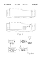
- FIG. 2 shows line-of-sight, as well as one bounce specular reception.
- FIG. 3 is a schematic representation of various cell-sites of the present disclosure.
- FIG. 4A is an example of the use of cell-site diversity to maximize the signal to a shadowed subscriber.
- FIG. 4B shows possible examples of the population density versus mean signal strength for various locations about four cells shown in FIG. 4A.
- FIG. 5 is a corner-excited system of the present disclosure.
- FIG. 6A is a block diagram of an adaptive beam steering receiver.
- FIG. 6B is a block diagram of an adaptive beam steering and positioning receiver.
- the disclosure of the present invention is based upon the assumption that the coverage plan must efficiently accommodate service to non-line-of-sight subscribers without the use of repeaters as the mechanism by which to mitigate shadows due to large high rise structures and other atmospheric influences. Assuming that the majority of potential subscribers within an urban coverage area occupy non-line-of-sight residences, it is clear that a non-line-of-sight system must, in effect, meet both system performance and cost requirements.
- the servicing of non-line-of-sight subscribers can be addressed by examining the consequences of a propagation model which utilizes one specular or coherent reflection to reach a shadowed subscriber.
- the disclosure of the present invention does not rely upon repeaters to effect communication to shadowed subscribers, but rather uses a cell-site network which effects the best signal possible to a given subscriber using cell-site diversity.
- Case 1 is free space or line-of-sight reception, the basis for statistical analysis in the present disclosure.
- CNR carrier-to-noise ratio
- LOS line-of-sight.
- P t is the power delivered to the transmit antenna
- G t is the transmit antenna gain
- G r is the receive antenna gain
- F r is the noise figure of the receiver
- k is Boltzman's constant
- T 0 room temperature in Kelvin
- B c is channel bandwidth
- L R is the attenuation due to rain as a function of range
- R is the range
- lambda is the free space wavelength.
- the non-line-of-sight range is the line-of-sight range multiplied by a factor ( ⁇ 2 ) which accounts for a reflection before the signal impinges upon the subscriber antenna. Accordingly, from straight forward analysis, it can be seen that the non-line-of-sight range, ⁇ 2 ⁇ R LOS is a particular fraction of the line-of-sight range for the same 22 dB where acceptable reception levels are realized.
- the 1.1 parameter presumes the statistical pathlengths for the specular components are on the order of one-tenth of the free space transmission path length.
- the magnitude of the reflection coefficient will be a function of the properties of the reflecting material, the thickness of the material and the condition of its surface, as well as the angle of incidents.
- the parameter associated with the reflection in the propagation model is dealt with statistically as having a mean with an associated distribution.
- glass is the material primarily responsible for specular reflections
- metal surfaces would increase the mean reflection when compared to glass; concrete or brick surfaces would, most likely have mean reflections similar to or less than that for glass.
- the mean range for a single reflection case is 0.25 R LOS , which represents a significant reduction in range.
- the difference between the Case 1 line-of-sight and Case 2 one-bounce models is on the order of 2:1 in range.
- the acceptable signal level service area of the non-line of sight model is reduced by a factor of four when compared to the line-of-sight model.
- the final result, in such a system requires four times more cell-sites in the "one-bounce" non-line-of-sight scenario than is required in the line-of-sight scenario. This of course, means that four times as many subscribers are needed to support the added infrastructure. This is certainly an achievable number in densely populated urban areas.
- the system disclosed herein is neither simply a center-excited plan nor a corner-excited plan.
- the structure of the present disclosure embraces the flexibility and co-existence of both by permitting a relatively simple noise limited, center-excited omni-directional coverage algorithm for start-up systems as well as an evolution to a mature, interference-limited directional coverage algorithm where cell-site antenna directivity may be required for channel set isolation from cell to cell.
- the coverage plan proposed in this disclosure is to be viewed as flexible, dynamic and macroscopically adaptive through the use of geometry and propagation statistics in the determination of the cell-site deployment.
- the system of the present disclosure accommodates various levels of system maturity and capacity, making selective use of both center and peripherally excited cells; both omni-directional and directional cell-site antennas; and the co-existence of various cell sizes within a coverage area.
- millimeter wavelengths are susceptible to several environmentally and atmospherically induced forms of fading.
- rain is viewed as being one of the most severe forms of millimeter wave degradation, manifested in the form of signal attenuation due to absorption.
- attenuation levels can be as high as 5 dB per mile.
- Rain can also be responsible for subtle forms of fading in the sense that the surface of any dominant specular reflector when wet can cause the reflected beam to distort or shift away from the centroid of the subscriber unit antenna pattern.
- Adaptive reception is to include both installer and subscriber to position and orient the antenna at the subscriber's site to effect the best signal-to-interference plus noise ratio.
- fading can occur at the subscriber antenna due to multiple reflections, which are impingent from different reflectors that are within the reception angle of the antenna.
- the use of very high gain subscriber antennas can selectively eliminate or substantially reduce this form of multi-path fading. If not, adaptive reception can be used to eliminate or substantially reduce multi-path fading. The details of adaptive reception are described herein below.
- the effect of fading at a subscriber's antenna could be described as a shift in the specular reflected beam and/or a position shift of the local signal strength maximum or both.
- Microscopic propagation statistics at millimeter wave frequencies do not distinguish among the occurrence probabilities of the various forms of fading. Intuitively, it serves to reason that most of the fading occurrences are likely to be modeled as shifts in the beam centroid of the reflected signal. In some instances of multi-path fading, a position shift of the signal strength maximum is likely to be manifested as well.
- a one-way broadcast system where the majority of the reused channels carry identical information.
- a typical broadcast layout for the one-way broadcast system is as shown in FIG. 3.
- Center-excited omni-directional cell-sites 301 labeled A, B, C, D for purposes of discussion, are located at roughly twice the expected line-of-sight range of each transmitter.
- a one-way broadcast system would require one transmit site for a given service area if enough carrier power should be made available.
- current art in millimeter wave transmitters restricts the range of acceptable mean signal power to a few miles. Accordingly, a network of transmitters must be deployed to service a large area of subscribers requiring, therefore, the reuse of the broadcast channels throughout the coverage area.
- the measure of acceptable distortion is usually given in terms of carrier-to-interface (C/I) ratios at the subscriber's receiver.
- C/I carrier-to-interface
- co-channel interference at a subscriber's antenna within a given cell-site coverage can be restricted by delineating the distances from serving and potentially interfering cell-sites. That is, the carrier to interference ratio is a function of the distance ratio raised to some power which is usually 2 or more.
- acceptable cell radii are distances where the 22 dB carrier/interference level is reached. Accordingly, by repeating a particular frequency at a distance which is great enough, the co-channel interference by frequency reuse is substantially avoided.
- Segmentation of cell-site transmit antennas into directive antennas can be used to confine channels to specific coverage areas.
- orthogonal polarization of co-channel transmission can be used to isolate signals from one another within the same coverage area. For the purposes of example, consider cell-site A(302) which transmits at frequency channel-set F1 using a vertically polarized antenna, designated F1V(303). Cell-site B(304) adjacent cell-site A(302) transmits frequency channel set F2 using a vertically polarized antenna designated F2V(305).
- Cell-site C(306) transmits frequency channel-set F1 using a horizontally polarized antenna designated F1H(307), while cell-site D(308) transmits frequency channel-set F2 using a horizontally polarized antenna designated F2H(309) .
- Each specific channel within the frequency channel-set F2 is adjacent to two specific channels with a frequency channel-set F1. Consequently, the system of FIG. 4 must accommodate signal strength constraints relating to both co-channel interference and adjacent channel interference.
- the present invention relies upon statistical probability to determine a surrounding cell-site transmitter B, C or D which can provide subscriber S with an acceptable signal, for example 22 dB as discussed above.
- a surrounding cell-site transmitter B, C or D which can provide subscriber S with an acceptable signal, for example 22 dB as discussed above.
- Disclosure of the present invention relies upon the one-bounce model, proposed and described above, as a guideline in the layout of a millimeter wave distribution system.
- the one-bounce statistical propagation model of the present disclosure is also known as cell-site diversity.
- FIG. 4A a scenario is shown where significant portions of a given cell are shadowed by man-made structures.
- the subscribers within the areas shadowed from the serving cell-site for example S1, shown as 401 are serviced by use of one or more repeaters strategically located to deliver acceptable signals within the shadowed zone. Locating, installing and maintaining the number of repeaters necessary to cover a large and evolving urban center is cumbersome and unpredictable. Additionally, the impact of the required number of repeaters on co-channel and adjacent channel interference is deleterious to, if not defeating of the purpose of the repeaters.
- the disclosure of the present invention allow the subscriber unit to be serviced by any one of the surrounding cell-sites.
- the choice of cell-site service which is limited in the prior art to the propagation path geographically supported by a given cell-site, would be extended to multiple cell-sites. Implementation of such a system improves the carrier to noise ratio by as much as 3 or 4 dB.
- FIG. 4B four graphical representations are shown.
- the graphs are population density versus mean signal strength.
- Population density is the fraction of occurrences that have a particular value of signal strength at a given radius.
- Graph I shows the signal distribution for cell-site A(1); graph II for cell-site B; graph III for cell-site C; and graph IV for cell-site D.
- the signals received are uncorrelated normal signal power distributions from the four cell-sites each at distances which intersect the shadowed area to be served shown in FIG. 4A as S1.
- the opportunity to choose the best of the four cell-site candidates provides the expected carrier-to-noise ratio improvement.
- the installer would clearly choose to receive service at S1 from cell-site B which offers the highest signal strength.
- Another way to view the diversity of choosing the best of any of the surrounding cell-sites is that it statistically increases the radius or R NLOS of each cell-site.
- Statistical analysis shows that implementation of a system, for example as is shown in FIG. 4A, increases the radius up to 50%, which is effectively the same as increasing the cell size. Thereby, a reduction in required infrastructure is realized.
- the subscriber unit must be able to detect channels of both frequency sets F1 and F2 in the scenario shown in FIGS. 4A and 4B.
- the antenna of the cell-sites must be able to isolate the reception of vertically and horizontally polarized signals, selectively. Practical antenna isolations that have been realized in cellular distribution systems using polarization are on the order of 20 dB to 25 dB. If the adjacent channels are spaced too closely in frequency, or if the isolation achievable with antenna polarization is not great enough, then it is also necessary to use directivity of the antennas at the cell-sites. Again, such additions to the infrastructure may be required as the more mature environmental settings are realized.
- a second embodiment of the present invention utilizes a two-way coverage plan, illustrated in FIG. 5.
- directive cell-site antennas are used to provide coverage selectively to a confined segment of a cellular grid.
- the choice of the specific cellular coverage plan is usually made on the basis of spectral efficiency or, how many times a given channel-set can be reused within a given service area.
- the location of cell-site channel sets is determined by the estimated signal strength level of both co-channel and adjacent channel interference intercepted at both the subscriber and cell-site antennas.
- the effective isotropic power radiated per unit bandwidth for both cell-sites and subscribers is approximately equal.
- the reuse of a particular frequency segment is constrained by the interference distortions produced when a given subscriber unit is allowed by layout geometry to receive co-channel or adjacent channel carriers from two or more cell-sites which have similar signal strength levels.
- the carrier to interference ratio at the subscriber unit is the ratio of co-channel cell-site to serving cell-site distances raised to the power of 2, using the model disclosed in FIG. 2 for one-bounce modeling. Such a scenario would suggest that the ratio of distances would have to be in the order of 12:1 to achieve the required C/I of 22 dB. Such a system would not be practical.
- FIG. 5 is an example of how all the many features could be implemented.
- the grid array for cell-sites shown in FIG. 2 envisions corner-excited cells at frequencies denoted in FIG. 5 as 1, 2, 3 and 4, with the requisite polarization diversity, and directivity as disclosed hereinabove.
- certain types of fading can be mitigated by adaptive reception using radar-like sensing functions that continually update the subscriber antenna beam pointing direction to maintain its focus on the maximum signal strength from a variety of cell-sites as is discussed in combination with FIGS. 4A and 4B.
- Such systems as are shown in FIGS. 6A and 6B are two of many approaches that can be used to optimize signal strength reception on a continual basis, reducing manual input at the subscriber site either by the subscriber or by the installer.
- Fades due to multi-path reflection may require a virtual position adjustment in addition to beam pointing adjustment in the subscriber antenna.
- the effective antenna aperture may be moved by roughly one-quarter wavelength or approximately 0.1", at the 28 GHz carrier frequency. This is done by implementing two or more overlay patch array apertures spaced in the order of one-quarter wavelength apart on a printed circuit board. The output port of each antenna would then be switched into the receiver, as necessary to maintain an acceptable signal strength.
Abstract
Description
Claims (17)
Priority Applications (1)
| Application Number | Priority Date | Filing Date | Title |
|---|---|---|---|
| US08/866,793 US6141557A (en) | 1996-05-31 | 1997-05-30 | LMDS system having cell-site diversity and adaptability |
Applications Claiming Priority (2)
| Application Number | Priority Date | Filing Date | Title |
|---|---|---|---|
| US1872496P | 1996-05-31 | 1996-05-31 | |
| US08/866,793 US6141557A (en) | 1996-05-31 | 1997-05-30 | LMDS system having cell-site diversity and adaptability |
Publications (1)
| Publication Number | Publication Date |
|---|---|
| US6141557A true US6141557A (en) | 2000-10-31 |
Family
ID=26691422
Family Applications (1)
| Application Number | Title | Priority Date | Filing Date |
|---|---|---|---|
| US08/866,793 Expired - Lifetime US6141557A (en) | 1996-05-31 | 1997-05-30 | LMDS system having cell-site diversity and adaptability |
Country Status (1)
| Country | Link |
|---|---|
| US (1) | US6141557A (en) |
Cited By (26)
| Publication number | Priority date | Publication date | Assignee | Title |
|---|---|---|---|---|
| US6393290B1 (en) * | 1999-06-30 | 2002-05-21 | Lucent Technologies Inc. | Cost based model for wireless architecture |
| US6546254B2 (en) * | 2001-02-06 | 2003-04-08 | Ip Mobilenet, Inc. | Method and apparatus for intelligent dynamic frequency reuse |
| US6560213B1 (en) * | 1999-03-24 | 2003-05-06 | Hrl Laboratories, Llc | Wideband wireless access local loop based on millimeter wave technology |
| US6665279B1 (en) * | 1998-11-27 | 2003-12-16 | Lg Information & Communications, Ltd. | Wide band wireless multimedia communication system |
| US6678259B1 (en) * | 1999-05-26 | 2004-01-13 | Qwest Communications International, Inc. | System and method for line of sight path communication |
| US20040190481A1 (en) * | 1998-02-11 | 2004-09-30 | King Scott William | Micro wave cellular architecture |
| US6847820B1 (en) * | 2000-07-24 | 2005-01-25 | Alcatel Canada Inc. | Slanted hub layout for wireless networks |
| US6879192B2 (en) | 2001-10-18 | 2005-04-12 | L-3 Communications Corporation | Even harmonic mixer with high-input, third-order intercept point |
| US20050177854A1 (en) * | 1998-02-27 | 2005-08-11 | Sharp Kabushiki Kaisha | Milliwave transmitting device, milliwave receiving device and milliwave transmission and reception system capable of simplifying wiring of a receiving system of terrestrial broadcasting service and satellite broadcasting service |
| US20070109193A1 (en) * | 2005-11-15 | 2007-05-17 | Clearone Communications, Inc. | Anti-reflective interference antennas with radially-oriented elements |
| US20070111749A1 (en) * | 2005-11-15 | 2007-05-17 | Clearone Communications, Inc. | Wireless communications device with reflective interference immunity |
| US20070109194A1 (en) * | 2005-11-15 | 2007-05-17 | Clearone Communications, Inc. | Planar anti-reflective interference antennas with extra-planar element extensions |
| US20080095042A1 (en) * | 2006-10-18 | 2008-04-24 | Mchenry Mark A | Methods for using a detector to monitor and detect channel occupancy |
| US20080318583A1 (en) * | 2007-03-21 | 2008-12-25 | Metropcs | Method for creating a cellular telephone infrastructure |
| US20100097952A1 (en) * | 2006-05-12 | 2010-04-22 | Shared Spectrum Company | Method and System for Classifying Communication Signals in a Dynamic Spectrum Access System |
| US8055204B2 (en) | 2007-08-15 | 2011-11-08 | Shared Spectrum Company | Methods for detecting and classifying signals transmitted over a radio frequency spectrum |
| US8064840B2 (en) | 2006-05-12 | 2011-11-22 | Shared Spectrum Company | Method and system for determining spectrum availability within a network |
| USRE43066E1 (en) * | 2000-06-13 | 2012-01-03 | Shared Spectrum Company | System and method for reuse of communications spectrum for fixed and mobile applications with efficient method to mitigate interference |
| US8184678B2 (en) | 2003-06-10 | 2012-05-22 | Shared Spectrum Company | Method and system for transmitting signals with reduced spurious emissions |
| US8184653B2 (en) | 2007-08-15 | 2012-05-22 | Shared Spectrum Company | Systems and methods for a cognitive radio having adaptable characteristics |
| US8326313B2 (en) | 2006-05-12 | 2012-12-04 | Shared Spectrum Company | Method and system for dynamic spectrum access using detection periods |
| US20130281103A1 (en) * | 2008-03-27 | 2013-10-24 | Broadcom Corporation | Channel frequency reuse for narrow beam video streaming based upon mobile terminal location information |
| US8818283B2 (en) | 2008-08-19 | 2014-08-26 | Shared Spectrum Company | Method and system for dynamic spectrum access using specialty detectors and improved networking |
| US8997170B2 (en) | 2006-12-29 | 2015-03-31 | Shared Spectrum Company | Method and device for policy-based control of radio |
| US9538388B2 (en) | 2006-05-12 | 2017-01-03 | Shared Spectrum Company | Method and system for dynamic spectrum access |
| US11070990B1 (en) * | 2020-01-16 | 2021-07-20 | T-Mobile Usa, Inc. | Systems and methods for maintaining network quality |
Citations (17)
| Publication number | Priority date | Publication date | Assignee | Title |
|---|---|---|---|---|
| EP0201254A2 (en) * | 1985-05-03 | 1986-11-12 | AT&T Corp. | Terrestrial communications system base station |
| US5365571A (en) * | 1993-05-24 | 1994-11-15 | Hughes Aircraft Company | Cellular system having frequency plan and cell layout with reduced co-channel interference |
| US5463673A (en) * | 1993-04-29 | 1995-10-31 | Northern Telecom Limited | In-building radio deployment technique for wireless personal communications systems |
| US5483667A (en) * | 1993-07-08 | 1996-01-09 | Northern Telecom Limited | Frequency plan for a cellular network |
| US5507034A (en) * | 1993-09-01 | 1996-04-09 | Telefonaktiebolaget Lm Ericsson | Channel selection in a cellular communication system |
| US5519409A (en) * | 1993-10-08 | 1996-05-21 | Nippon Steel Corporation | Plane array antenna for receiving satellite broadcasting |
| US5537122A (en) * | 1994-07-22 | 1996-07-16 | Japan Radio Co., Ltd. | Tracking array antenna system |
| US5559866A (en) * | 1992-06-01 | 1996-09-24 | Motorola, Inc. | Method of reuse through remote antenna and same channel cell division |
| US5644791A (en) * | 1993-11-30 | 1997-07-01 | International Business Machines Corporation | System for storing pointers to initial sectors of variable length n units and storing second pointers within the initial sector of the n unit |
| US5646942A (en) * | 1995-03-16 | 1997-07-08 | Bell Atlantic Network Services, Inc. | Simulcast transmission of digital programs to shared antenna receiving systems |
| US5668610A (en) * | 1995-12-04 | 1997-09-16 | Cellularvision Technology & Telecommunications, L.P. | LMDS transmitter array with polarization-diversity sub-cells |
| WO1997046040A2 (en) * | 1996-05-31 | 1997-12-04 | The Whitaker Corporation | Lmds system having cell-site diversity and adaptability |
| US5809431A (en) * | 1995-12-06 | 1998-09-15 | Stanford Telecommunications, Inc. | Local multipoint distribution system |
| US5828960A (en) * | 1995-03-31 | 1998-10-27 | Motorola, Inc. | Method for wireless communication system planning |
| US5828962A (en) * | 1996-04-18 | 1998-10-27 | France Telecom | Process for analyzing traffic localization within a cellular radiocommunication network |
| US5926762A (en) * | 1996-05-17 | 1999-07-20 | Internet Mobility Corporation | Cellular telephone interference prediction and frequency reuse planning |
| US5987328A (en) * | 1997-04-24 | 1999-11-16 | Ephremides; Anthony | Method and device for placement of transmitters in wireless networks |
-
1997
- 1997-05-30 US US08/866,793 patent/US6141557A/en not_active Expired - Lifetime
Patent Citations (17)
| Publication number | Priority date | Publication date | Assignee | Title |
|---|---|---|---|---|
| EP0201254A2 (en) * | 1985-05-03 | 1986-11-12 | AT&T Corp. | Terrestrial communications system base station |
| US5559866A (en) * | 1992-06-01 | 1996-09-24 | Motorola, Inc. | Method of reuse through remote antenna and same channel cell division |
| US5463673A (en) * | 1993-04-29 | 1995-10-31 | Northern Telecom Limited | In-building radio deployment technique for wireless personal communications systems |
| US5365571A (en) * | 1993-05-24 | 1994-11-15 | Hughes Aircraft Company | Cellular system having frequency plan and cell layout with reduced co-channel interference |
| US5483667A (en) * | 1993-07-08 | 1996-01-09 | Northern Telecom Limited | Frequency plan for a cellular network |
| US5507034A (en) * | 1993-09-01 | 1996-04-09 | Telefonaktiebolaget Lm Ericsson | Channel selection in a cellular communication system |
| US5519409A (en) * | 1993-10-08 | 1996-05-21 | Nippon Steel Corporation | Plane array antenna for receiving satellite broadcasting |
| US5644791A (en) * | 1993-11-30 | 1997-07-01 | International Business Machines Corporation | System for storing pointers to initial sectors of variable length n units and storing second pointers within the initial sector of the n unit |
| US5537122A (en) * | 1994-07-22 | 1996-07-16 | Japan Radio Co., Ltd. | Tracking array antenna system |
| US5646942A (en) * | 1995-03-16 | 1997-07-08 | Bell Atlantic Network Services, Inc. | Simulcast transmission of digital programs to shared antenna receiving systems |
| US5828960A (en) * | 1995-03-31 | 1998-10-27 | Motorola, Inc. | Method for wireless communication system planning |
| US5668610A (en) * | 1995-12-04 | 1997-09-16 | Cellularvision Technology & Telecommunications, L.P. | LMDS transmitter array with polarization-diversity sub-cells |
| US5809431A (en) * | 1995-12-06 | 1998-09-15 | Stanford Telecommunications, Inc. | Local multipoint distribution system |
| US5828962A (en) * | 1996-04-18 | 1998-10-27 | France Telecom | Process for analyzing traffic localization within a cellular radiocommunication network |
| US5926762A (en) * | 1996-05-17 | 1999-07-20 | Internet Mobility Corporation | Cellular telephone interference prediction and frequency reuse planning |
| WO1997046040A2 (en) * | 1996-05-31 | 1997-12-04 | The Whitaker Corporation | Lmds system having cell-site diversity and adaptability |
| US5987328A (en) * | 1997-04-24 | 1999-11-16 | Ephremides; Anthony | Method and device for placement of transmitters in wireless networks |
Non-Patent Citations (8)
| Title |
|---|
| C. Rypinski, "Economic design of Interference limited Radiotelephone Systems", XP 002048287, 3rd IEEE Vehicular Technology Conference, Toronto, Canada, May 25-27, 1983, pp. 332-340. |
| C. Rypinski, Economic design of Interference limited Radiotelephone Systems , XP 002048287, 3rd IEEE Vehicular Technology Conference, Toronto, Canada, May 25 27, 1983, pp. 332 340. * |
| Fujii T: "Effect of Reduction of Mobile Communications Co-Channel Interference by Transmission Power Control Considering Received Signal Level Correlations" Electronics & Communications in Japan, Part I--Communications, vol. 76, No. 9, Sep. 1, 1993, pp. 89-103. |
| Fujii T: Effect of Reduction of Mobile Communications Co Channel Interference by Transmission Power Control Considering Received Signal Level Correlations Electronics & Communications in Japan, Part I Communications, vol. 76, No. 9, Sep. 1, 1993, pp. 89 103. * |
| Rypinski C A: "Economic design of interference limited radiotelephone systems" 33rd IEEE Vehicular Technology Conference, Toronto, ONT1, Canada, May 25-27, 1983, pp. 332-340. |
| Rypinski C A: Economic design of interference limited radiotelephone systems 33 rd IEEE Vehicular Technology Conference, Toronto, ONT1, Canada, May 25 27, 1983, pp. 332 340. * |
| T. Fujii, "Effect of reduction of Mobile Communications Co-channel Interference by Transmission Power Control considering received Signal Level Correlations", Electronics and Communications in Japan, Part 1, vol. 76, No. 9, 1993, pp. 89-103. |
| T. Fujii, Effect of reduction of Mobile Communications Co channel Interference by Transmission Power Control considering received Signal Level Correlations , Electronics and Communications in Japan, Part 1, vol. 76, No. 9, 1993, pp. 89 103. * |
Cited By (50)
| Publication number | Priority date | Publication date | Assignee | Title |
|---|---|---|---|---|
| US20040190481A1 (en) * | 1998-02-11 | 2004-09-30 | King Scott William | Micro wave cellular architecture |
| US7403500B2 (en) | 1998-02-11 | 2008-07-22 | Scott William King | Micro wave cellular architecture |
| US20050177854A1 (en) * | 1998-02-27 | 2005-08-11 | Sharp Kabushiki Kaisha | Milliwave transmitting device, milliwave receiving device and milliwave transmission and reception system capable of simplifying wiring of a receiving system of terrestrial broadcasting service and satellite broadcasting service |
| US6665279B1 (en) * | 1998-11-27 | 2003-12-16 | Lg Information & Communications, Ltd. | Wide band wireless multimedia communication system |
| US6560213B1 (en) * | 1999-03-24 | 2003-05-06 | Hrl Laboratories, Llc | Wideband wireless access local loop based on millimeter wave technology |
| US6678259B1 (en) * | 1999-05-26 | 2004-01-13 | Qwest Communications International, Inc. | System and method for line of sight path communication |
| US6393290B1 (en) * | 1999-06-30 | 2002-05-21 | Lucent Technologies Inc. | Cost based model for wireless architecture |
| USRE46905E1 (en) | 2000-06-13 | 2018-06-19 | Shared Spectrum Company | System and method for reuse of communications spectrum for fixed and mobile applications with efficient method to mitigate interference |
| USRE43066E1 (en) * | 2000-06-13 | 2012-01-03 | Shared Spectrum Company | System and method for reuse of communications spectrum for fixed and mobile applications with efficient method to mitigate interference |
| USRE44237E1 (en) | 2000-06-13 | 2013-05-21 | Shared Spectrum Company | System and method for reuse of communications spectrum for fixed and mobile applications with efficient method to mitigate interference |
| USRE47120E1 (en) | 2000-06-13 | 2018-11-06 | Shared Spectrum Company | System and method for reuse of communications spectrum for fixed and mobile applications with efficient method to mitigate interference |
| USRE44492E1 (en) * | 2000-06-13 | 2013-09-10 | Shared Spectrum Company | System and method for reuse of communications spectrum for fixed and mobile applications with efficient method to mitigate interference |
| US6847820B1 (en) * | 2000-07-24 | 2005-01-25 | Alcatel Canada Inc. | Slanted hub layout for wireless networks |
| US6546254B2 (en) * | 2001-02-06 | 2003-04-08 | Ip Mobilenet, Inc. | Method and apparatus for intelligent dynamic frequency reuse |
| US6879192B2 (en) | 2001-10-18 | 2005-04-12 | L-3 Communications Corporation | Even harmonic mixer with high-input, third-order intercept point |
| US8184678B2 (en) | 2003-06-10 | 2012-05-22 | Shared Spectrum Company | Method and system for transmitting signals with reduced spurious emissions |
| US20070111749A1 (en) * | 2005-11-15 | 2007-05-17 | Clearone Communications, Inc. | Wireless communications device with reflective interference immunity |
| US7480502B2 (en) | 2005-11-15 | 2009-01-20 | Clearone Communications, Inc. | Wireless communications device with reflective interference immunity |
| US7446714B2 (en) | 2005-11-15 | 2008-11-04 | Clearone Communications, Inc. | Anti-reflective interference antennas with radially-oriented elements |
| US7333068B2 (en) | 2005-11-15 | 2008-02-19 | Clearone Communications, Inc. | Planar anti-reflective interference antennas with extra-planar element extensions |
| US20070109194A1 (en) * | 2005-11-15 | 2007-05-17 | Clearone Communications, Inc. | Planar anti-reflective interference antennas with extra-planar element extensions |
| US20070109193A1 (en) * | 2005-11-15 | 2007-05-17 | Clearone Communications, Inc. | Anti-reflective interference antennas with radially-oriented elements |
| US8155649B2 (en) | 2006-05-12 | 2012-04-10 | Shared Spectrum Company | Method and system for classifying communication signals in a dynamic spectrum access system |
| US20100097952A1 (en) * | 2006-05-12 | 2010-04-22 | Shared Spectrum Company | Method and System for Classifying Communication Signals in a Dynamic Spectrum Access System |
| US9538388B2 (en) | 2006-05-12 | 2017-01-03 | Shared Spectrum Company | Method and system for dynamic spectrum access |
| US8064840B2 (en) | 2006-05-12 | 2011-11-22 | Shared Spectrum Company | Method and system for determining spectrum availability within a network |
| US9900782B2 (en) | 2006-05-12 | 2018-02-20 | Shared Spectrum Company | Method and system for dynamic spectrum access |
| US8326313B2 (en) | 2006-05-12 | 2012-12-04 | Shared Spectrum Company | Method and system for dynamic spectrum access using detection periods |
| US20080095042A1 (en) * | 2006-10-18 | 2008-04-24 | Mchenry Mark A | Methods for using a detector to monitor and detect channel occupancy |
| US8027249B2 (en) | 2006-10-18 | 2011-09-27 | Shared Spectrum Company | Methods for using a detector to monitor and detect channel occupancy |
| US8559301B2 (en) | 2006-10-18 | 2013-10-15 | Shared Spectrum Company | Methods for using a detector to monitor and detect channel occupancy |
| US10070437B2 (en) | 2006-10-18 | 2018-09-04 | Shared Spectrum Company | Methods for using a detector to monitor and detect channel occupancy |
| US9491636B2 (en) | 2006-10-18 | 2016-11-08 | Shared Spectrum Company | Methods for using a detector to monitor and detect channel occupancy |
| US9215710B2 (en) | 2006-10-18 | 2015-12-15 | Shared Spectrum Company | Methods for using a detector to monitor and detect channel occupancy |
| US10484927B2 (en) | 2006-12-29 | 2019-11-19 | Shared Spectrum Company | Method and device for policy-based control of radio |
| US8997170B2 (en) | 2006-12-29 | 2015-03-31 | Shared Spectrum Company | Method and device for policy-based control of radio |
| US20080318583A1 (en) * | 2007-03-21 | 2008-12-25 | Metropcs | Method for creating a cellular telephone infrastructure |
| US8185122B2 (en) * | 2007-03-21 | 2012-05-22 | Metropcs Wireless, Inc. | Method for creating a cellular telephone infrastructure |
| US9854461B2 (en) | 2007-08-15 | 2017-12-26 | Shared Spectrum Company | Methods for detecting and classifying signals transmitted over a radio frequency spectrum |
| US8793791B2 (en) | 2007-08-15 | 2014-07-29 | Shared Spectrum Company | Methods for detecting and classifying signals transmitted over a radio frequency spectrum |
| US8767556B2 (en) | 2007-08-15 | 2014-07-01 | Shared Spectrum Company | Systems and methods for a cognitive radio having adaptable characteristics |
| US8755754B2 (en) | 2007-08-15 | 2014-06-17 | Shared Spectrum Company | Methods for detecting and classifying signals transmitted over a radio frequency spectrum |
| US10104555B2 (en) | 2007-08-15 | 2018-10-16 | Shared Spectrum Company | Systems and methods for a cognitive radio having adaptable characteristics |
| US8184653B2 (en) | 2007-08-15 | 2012-05-22 | Shared Spectrum Company | Systems and methods for a cognitive radio having adaptable characteristics |
| US8055204B2 (en) | 2007-08-15 | 2011-11-08 | Shared Spectrum Company | Methods for detecting and classifying signals transmitted over a radio frequency spectrum |
| US9282540B2 (en) * | 2008-03-27 | 2016-03-08 | Broadcom Corporation | Channel frequency reuse for narrow beam video streaming based upon mobile terminal location information |
| US20130281103A1 (en) * | 2008-03-27 | 2013-10-24 | Broadcom Corporation | Channel frequency reuse for narrow beam video streaming based upon mobile terminal location information |
| US8818283B2 (en) | 2008-08-19 | 2014-08-26 | Shared Spectrum Company | Method and system for dynamic spectrum access using specialty detectors and improved networking |
| US11070990B1 (en) * | 2020-01-16 | 2021-07-20 | T-Mobile Usa, Inc. | Systems and methods for maintaining network quality |
| US11665557B2 (en) | 2020-01-16 | 2023-05-30 | T-Mobile Usa, Inc. | Systems and methods for maintaining network quality |
Similar Documents
| Publication | Publication Date | Title |
|---|---|---|
| US6141557A (en) | LMDS system having cell-site diversity and adaptability | |
| US6418327B1 (en) | Methods and determining an optimum sector distribution within a coverage area of a wireless communication system | |
| US6118767A (en) | Interference control for CDMA networks using a plurality of narrow antenna beams and an estimation of the number of users/remote signals present | |
| US8718541B2 (en) | Techniques for optimal location and configuration of infrastructure relay nodes in wireless networks | |
| US5355520A (en) | In-building microwave communication system permits frequency refuse with external point-to-point microwave systems | |
| US20050250503A1 (en) | Wireless networks frequency reuse distance reduction | |
| EP0851698A2 (en) | Wireless communication systems | |
| KR19980703368A (en) | Wide antenna robe | |
| Williamson et al. | Investigating the effects of antenna directivity on wireless indoor communication at 60 GHz | |
| US20220338024A1 (en) | Passive intermodulation interference optimized antenna configuration | |
| US5960343A (en) | Mobile communications | |
| US20020151309A1 (en) | Scalable sector wide area networks in wireless communication systems | |
| EP0994632A2 (en) | Frequency reuse scheme for point to multipoint radio communications | |
| EP0903048B1 (en) | Lmds system having cell-site diversity and adaptability | |
| Gong et al. | Cochannel interference in cellular fixed broadband access systems with directional antennas | |
| US6127988A (en) | Fixed wireless base station antenna arrangement | |
| KR100727076B1 (en) | Signal dispersion system and method thereof | |
| US7158813B2 (en) | Antenna for wireless systems | |
| US11330445B1 (en) | Adaptive sectoring of a wireless base station | |
| GB2367188A (en) | Shaped antenna beam | |
| WO2000060885A9 (en) | Point-to-multipoint two-way broadband wireless communication system | |
| JPH0447722A (en) | Radio channel assignment control method in mobile communication | |
| KR19990053963A (en) | Smart Antenna and Radiation Pattern Generation Method for Automatic Base Station Auto Discovery | |
| CN112235854B (en) | Power compensation method and device based on white spectrum optimal utilization technology | |
| US11223402B1 (en) | Assisted channel approximation for wireless communication of a supercell base station |
Legal Events
| Date | Code | Title | Description |
|---|---|---|---|
| STCF | Information on status: patent grant |
Free format text: PATENTED CASE |
|
| FPAY | Fee payment |
Year of fee payment: 4 |
|
| FPAY | Fee payment |
Year of fee payment: 8 |
|
| REMI | Maintenance fee reminder mailed | ||
| AS | Assignment |
Owner name: PINE VALLEY INVESTMENTS, INC., NEVADA Free format text: ASSIGNMENT OF ASSIGNORS INTEREST;ASSIGNORS:TYCO ELECTRONICS GROUP S.A.;TYCO ELECTRONICS CORPORATION;THE WHITAKER CORPORATION;AND OTHERS;REEL/FRAME:023065/0269 Effective date: 20090529 Owner name: PINE VALLEY INVESTMENTS, INC.,NEVADA Free format text: ASSIGNMENT OF ASSIGNORS INTEREST;ASSIGNORS:TYCO ELECTRONICS GROUP S.A.;TYCO ELECTRONICS CORPORATION;THE WHITAKER CORPORATION;AND OTHERS;REEL/FRAME:023065/0269 Effective date: 20090529 |
|
| AS | Assignment |
Owner name: HARRIS CORPORATION, FLORIDA Free format text: ASSIGNMENT OF ASSIGNORS INTEREST;ASSIGNOR:PINE VALLEY INVESTMENTS, LLC;REEL/FRAME:027529/0160 Effective date: 20120112 |
|
| REMI | Maintenance fee reminder mailed | ||
| FPAY | Fee payment |
Year of fee payment: 12 |
|
| SULP | Surcharge for late payment |
Year of fee payment: 11 |
|
| AS | Assignment |
Owner name: NORTH SOUTH HOLDINGS INC., NEW YORK Free format text: ASSIGNMENT OF ASSIGNORS INTEREST;ASSIGNOR:HARRIS CORPORATION;REEL/FRAME:030119/0804 Effective date: 20130107 |