US5801948A - Universal control system with alarm history tracking for mobile material distribution apparatus - Google Patents
Universal control system with alarm history tracking for mobile material distribution apparatus Download PDFInfo
- Publication number
- US5801948A US5801948A US08/697,311 US69731196A US5801948A US 5801948 A US5801948 A US 5801948A US 69731196 A US69731196 A US 69731196A US 5801948 A US5801948 A US 5801948A
- Authority
- US
- United States
- Prior art keywords
- microprocessor
- error
- control system
- user
- controlling
- Prior art date
- Legal status (The legal status is an assumption and is not a legal conclusion. Google has not performed a legal analysis and makes no representation as to the accuracy of the status listed.)
- Expired - Lifetime
Links
Images


Classifications
-
- G—PHYSICS
- G05—CONTROLLING; REGULATING
- G05B—CONTROL OR REGULATING SYSTEMS IN GENERAL; FUNCTIONAL ELEMENTS OF SUCH SYSTEMS; MONITORING OR TESTING ARRANGEMENTS FOR SUCH SYSTEMS OR ELEMENTS
- G05B23/00—Testing or monitoring of control systems or parts thereof
- G05B23/02—Electric testing or monitoring
- G05B23/0205—Electric testing or monitoring by means of a monitoring system capable of detecting and responding to faults
- G05B23/0259—Electric testing or monitoring by means of a monitoring system capable of detecting and responding to faults characterized by the response to fault detection
- G05B23/0264—Control of logging system, e.g. decision on which data to store; time-stamping measurements
Definitions
- This invention relates generally to control systems and more particularly to a universal control system with alarm history tracking for mobile material distribution apparatus such as farm implements and public works vehicles.
- Control systems for controlling the operation of mobile material distribution apparatus have been known for some time. Generally, these control systems are used to control the rates at which various products are dispersed or distributed. Exemplary applications where such control systems have been used include the control of farm machinery and implements such as sprayers and planters, and the control of public works vehicles such as salt spreaders for road maintenance and the like.
- U.S. Pat. Nos. 4,630,773 and Re. 35,100 which are both hereby incorporated by reference, disclose the use of microprocessor based control systems wherein the ground speed and the precise field position of the distribution apparatus, as well as the type of soil and other factors are monitored and employed to distribute a controlled amount of material throughout a field in farming applications.
- Prior art control systems have suffered from certain drawbacks. For example, early control systems were dedicated products designed for use with a specific implement or machine having a specific application. Under such an approach, it is necessary to have a dedicated control system for each material distribution apparatus owned. Thus, if a farmer utilizes both a sprayer and a planter on his/her farm, that farmer would require a dedicated control system for each of these two implements. As a result, the end user incurred excessive costs in both purchasing and maintaining two separate control systems as well as in providing training for multiple systems if more than one type of control system is employed.
- control systems typically require numerous inputs from sensors and actuators disposed on the implements they control.
- numerous cables In order to switch from one implement to another, numerous cables must be disconnected and others must be connected, thereby causing both time delays and the possibility of poorly connected and/or incorrectly connected wiring.
- prior art control systems require substantial software changes and configuration adjustments to adapt the system to the newly attached material distribution apparatus. Thus, switching between distribution devices with a single control system has often been difficult and time consuming.
- a boom is an elongated distribution tube usually positioned in a horizontal plane parallel to the ground, and having a plurality of nozzles or, in the case of booms for granular applications, distribution ports spaced along its length.
- a product to be dispensed is pumped into the elongated tube which delivers the product to the nozzles (or distribution ports) which, in turn, distribute the product onto the surface to be treated.
- Prior art control systems have had the capability of monitoring the operating state of the nozzles/distribution ports (i.e., open or closed), and, depending upon those operating states, adjusting the amount of product delivered to the tube to regulate the dispersal of the product to the field.
- these prior art systems did not monitor which of the nozzles/distribution ports were open or closed.
- These same systems often employ the global positioning system ("GPS") to monitor the amount of dispersant applied across a surface and to create a mapped record of such amounts.
- GPS global positioning system
- booms include two fence row nozzles, one at each opposite end of the elongated distribution tube.
- booms include only a single fence row nozzle disposed at one of its ends.
- Fence row nozzles usually have twice the capacity of the other nozzles on the boom and are typically used to spray the outer edge of a field, ditch bank or fence row adjacent to the field being serviced. Prior art control systems have ignored these fence row nozzles altogether. Thus, when one or more fence row nozzles are in use, the application rate selected by the control system for the product being dispersed can be inaccurate. In addition, since prior art control systems ignore the fence row nozzles, the material dispersed therethrough will not be recorded by GPS and the GPS maps will be inaccurate.
- Prior art control systems have also provided limited alarm systems. For example, when an error occurred, these systems typically would display a cryptic code on a display and would make an audible sound. The sound was typically the same regardless of the error. Thus, the audible error information provided by these systems provided no indication of the nature of the error. Further, the error message usually disappeared from the LCD within a relatively short period of time and was gone forever. Therefore, if the user did not read the error message within a relatively short time after the audible alarm sounded, he/she would never know the nature of the error message.
- the present invention accomplishes these objectives and overcomes the drawbacks of the prior art by providing a control system for controlling the operation of a mobile material distribution device.
- the control system includes an input device and an output device for interacting with a user. It also includes a microprocessor having at least one input port and at least one output port arranged to form at least one feedback loop for controlling an attached material distribution apparatus.
- the microprocessor is adapted to detect errors.
- the control system further includes a memory associated with the microprocessor for strong error identification information received from the microprocessor.
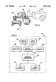
- FIGS. 1A and 1B are schematic diagrams illustrating a universal modular control system constructed in accordance with the teachings of the invention.
- FIG. 2 is a perspective view of an exemplary mobile material distribution apparatus employing the control system of FIG. 1.
- FIG. 3 is a schematic diagram illustrating the construction of the user console of the control system shown in FIG. 1A.
- FIG. 4 is a schematic diagram illustrating the construction of the control module of the control system shown in FIG. 1B.
- FIGS. 5A-5C comprise a flowchart illustrating the operation of the control module of the control system illustrated in FIG. 1B.
- FIG. 6 is a flowchart illustrating the CM-ERROR routine called in the flowchart of FIGS. 5A-5C.
- FIG. 7 is a flowchart illustrating the CM-MANUAL routine called in the flowchart of FIGS. 5A-5C.
- FIG. 8 is a flowchart illustrating the BOOM routine called in the flowchart of FIGS. 5A-5C.
- FIG. 9 comprises a flowchart illustrating the CHANNEL routine called in the flowchart of FIGS. 5A-5C.
- FIGS. 10A-10D comprise a flowchart illustrating the operation of the user console of the control system illustrated in FIG. 1A.
- FIGS. 11A-11C comprise a flowchart illustrating the OFF routine called in the flowchart of FIGS. 10A-10D.
- FIG. 12 is a flowchart illustrating the UC-MANUAL routine called in the flowchart of FIGS. 10A-10D.
- FIG. 13 comprises a flowchart illustrating the UC-ERROR routine called in the flowchart of FIGS. 10A-10D.
- FIGS. 14A-14D comprise a flowchart illustrating the OPERATE routine called by the flowchart of FIGS. 11A-11C.
- FIG. 15 is an illustration of an exemplary graphical representation of three booms monitored and controlled by the system of FIGS. 1A and 1B.
- FIG. 16 alternatively illustrates, in flowchart form, the operation of a preferred user console in accordance with the invention.
- FIGS. 1A and 1B show generally a universal modular control system 10 constructed in accordance with the teachings of the instant invention.
- a user can employ the inventive control system 10 to monitor and control the operation of virtually any material distribution apparatus having substantially any application.
- the inventive control system 10 when properly configured, can be used to control the operation of farm implements such as liquid sprayers, anhydrous ammonia applicators, and granular distributors such as seed planters and fertilizer spreaders. When properly configured, it can also be used to monitor and control public works vehicles such as salt spreaders. In view of this flexibility, it will be appreciated that the inventive control system 10 is particularly useful to a user who employs multiple material distribution apparatus 80 at different times because a single control system can be used to control any of these apparatus.
- farm implements such as liquid sprayers, anhydrous ammonia applicators, and granular distributors such as seed planters and fertilizer spreaders.
- granular distributors such as seed planters and fertilizer spreaders.
- public works vehicles such as salt spreaders.
- the inventive control system 10 is particularly useful to a user who employs multiple material distribution apparatus 80 at different times because a single control system can be used to control any of these apparatus.
- control system 10 is provided with two primary components, namely, a user console 20 and a control module 50.
- control module 50 is the control center of the system 10. It monitors the operation of the serviced distribution apparatus 80; it generates control signals and communicates them to the distribution apparatus 80; and, it records information concerning the operation and performance of both the control system 10 and the serviced distribution apparatus 80.
- the user console 20 is primarily an input/output device that provides the user with visual information concerning the performance and operation of the control system 10 and the serviced distribution apparatus 80. It also provides a user-friendly means for inputting information into the control system 10. Together these components 20, 50 provide a universal control system 10 which is capable of controlling a wide variety of machinery.
- the inventive control system 10 is preferably constructed such that only the user console 20 need be disposed within the cab 82 (FIG. 2).
- the control module 50 which, as mentioned above, is the control center of the system 10, can be mounted exterior to the cab 82. Since, with a limited exception for speed monitoring explained below, the control module 50 is the only component of the system 10 that is directly connected to the sensors and actuators of the controlled material distribution apparatus 80, the vast majority of the wiring required for electrical communication can be located exterior to the cab 82 by positioning the control module outside of the cab 82.
- a serial bus such as, for example, a CAN ("Controller Area Network" per Bosch specification CAN 2.0) bus 15
- the CAN bus 15 is, therefore, the only connecting cable that must enter the cab 82.
- control module 50 may be positioned within the cab 82 without departing from the scope or the spirit of the invention.
- the disclosed universal control system 10 may be used with a cabless material distribution apparatus without departing from the scope of the invention.
- the material distribution apparatus 80 may comprise a tractor or prime mover 84 used to pull one or more distribution implements 86, or it can be constructed as a single structure (not shown).
- the control module 50 can be disposed on the prime mover 84 (for instance, position A in FIG. 2), or it can be disposed on the pulled implement 86 itself (for example, position B in FIG. 2).
- the implement 86 has been shown as a non-descript block in FIG. 2.
- the non-descript block can be any distribution implement that a user wishes to control.
- the CAN bus 15 is preferably provided with a connector 17 for selectively detaching the control module 50 from the user console 20.
- This ability to separate these two components 20, 50 is particularly advantageous when the control module 50 is secured on a detachable implement 86, (for example, near position B in FIG. 2), because it permits the user to detach the implement 86 from the prime mover 84 in order to use the prime mover 84 with a second implement.
- the second implement 86 is also provided with a control module 50 (generally in the vicinity of position B in FIG. 2), simply connecting the control module 50 of the second implement 86 to the connector 17 of the CAN bus 15 will permit a user to utilize the control system 10 to monitor and control the second implement 86.
- a user can still switch between implements 86 with the inventive control system 10 even if only one control module 50 is employed.
- the control module 50 is mounted on the prime mover 84, a user can switch between detachable implements 86 by detaching all of the wiring associated with controlling the implement to be replaced from the control module 50, and attaching the wiring associated with the implement to be controlled to the control module 50 in its place. After identifying the new implement to the control system 10 via the user console 20, the control system 10 will be ready to monitor and operate the second implement.
- CAN bus is the preferred means for coupling the user console 20 and the control module 50, those skilled in the art will appreciate that other coupling means such as fiber optic cables or infrared links could be employed without departing from the scope or the spirit of the invention.
- the user console 20 is an input/output device that permits the user to communicate with the control system 10.
- the user console 20 is preferably provided with a display device 22, several input devices 24, and an annunciator 26 for producing audible information.
- the display device 22 comprises a liquid crystal display ("LCD").
- LCD liquid crystal display
- other display devices capable of providing the user with visual information concerning the operation of the control system 10 and the distribution apparatus 80 it services, such as CRT's and the like, could also be employed in this role without departing from the scope or the spirit of the invention.
- the user console 20 includes a plurality of input devices 24, any number of such devices could be employed without departing from the scope of the invention.
- the input devices comprise an alpha numeric keypad 28 for inputting data, a set of directional keys 29 for moving a cursor about the visual display 22 and incrementing/decrementing certain variables and turning specific channels on or off, an on-off power switch 31, a plurality of location keys 32 assigned to specific areas of the LCD 22 for selecting from one or more menus displayed on the LCD 22; a contrast switch 33 for controlling the contrast of the LCD 22; two special function keys 34; and three mode selection keys 35, 36, 37 whose functions are described below.
- the user console 20 is provided with a microprocessor 38.
- the microprocessor 38 is provided with an associated memory 40.
- the memory 40 is divided into a non-volatile memory such as a PROM for storing programmed instructions directing the operation of the microprocessor 38, and an addressable volatile memory for storing temporary data during operation. Any portion of the memory 40 can be implemented in a variety of ways, such as disks, tapes or other magnetic media, optical media, semiconductor memories, such as RAM, ROM, EPROM, flash memory, etc.
- the program memory is flash memory, with suitable non-volatile memory used to store constants and other data.
- the programmed instructions contained in the memory 40 control the operation of the microprocessor 38; dictating the images and information which are displayed on the display device 22 and ascribing meanings to the various keystrokes made via the input devices 24.
- the microprocessor 38 is coupled to various input and output ports which, for organizational purposes, are preferably grouped into two cab harnesses 41, 42.
- a first cab harness 41 is coupled to the CAN bus 15 which provides a communication link between the user console 20 and the control module 50.
- Cab harness 41 also includes power leads 43 for coupling the user console 20 to a power supply such as the battery of the prime mover 84.
- An ignition switch cable 44 is also provided to permit the control system 10 to be hard wired to the ignition system of the prime mover 84 such that the control system 10 automatically powers up and down whenever the prime mover 84 is turned on and off, respectively.
- the cab harness 41 is further provided with cable connectors 45 and 46 for optional connection to an external alarm and a master switch module 95, respectively.
- the external alarm could be employed, for example, to provide a visual alarm signal to a hearing impaired user or to a user operating in a noisy environment.
- the purpose of the master switch module 95 will be discussed in detail below.
- the second cab harness 42 is provided with two cable connections 47, 48.
- a first one of these cable connections 47 can be optionally used to couple the user console 20 to a speed sensor such as a radar device. If this option is elected, however, it may be necessary to pass a second cable (in addition to the CAN bus 15) through the bulkhead of the cab 82 as shown in FIG. 1A.
- a speed connection cable is made available in the cab by vehicle manufacturers thereby obviating the need for a user to add another cable to implement this option.
- the second cable connection via cab harness 42 is an RS-232 port 48.
- This RS-232 port 48 is a general purpose, input/output cable that permits the user console 20 to communicate with any of a number of peripheral devices.
- this port 48 can be coupled to a printer to permit the control system 10 to output information concerning the operation of the system 10 and/or the distribution apparatus 80 it controls. It can also be coupled to a computer (either a portable computer or a desktop through a modem) to perform remote control operation of the control system 10 and its serviced apparatus 80, to perform diagnostic procedures, and/or to download new or amended programmed instructions for use by the control system 10.
- the RS-232 port 48 could be employed to couple the control system 10 to a global positioning system to permit the control system 10 to interface with a system having maps recording data concerning the characteristics of the surface being serviced by the controlled distribution apparatus 80. Such access can be for the purpose of recording the distribution of material by the apparatus 80 or to provide the system 10 with variable setpoint information.
- the control system 10 is provided, via port 48, with site specific setpoint information from a GPS system, thereby permitting the control system 10 to control the distribution apparatus 80 such that precisely the amount of material required at each specific location in the field or area is distributed.
- port 48 could be used in other ways to provide the system 10 with remotely-provided control information.
- a system for sampling the soil or other site-specific parameters can generate, in near real-time, a control signal, such as a setpoint signal, and can convey such a signal to the system 10 via port 48 to control and vary system operation as a function of such parameters.
- a control signal such as a setpoint signal
- the settings of the RS-232 port can be selected by the user from a list of pre-defined, standard settings to enable the port to be used for communication with a wide variety of devices.
- the settings of the RS-232 port are set by microprocessor 38 of the user console 20 based upon the user's selections.
- the second cab harness 42 is also preferably provided with a third cable connection for use in sensing the operable axle of a two axle vehicle.
- the cab harnesses 41, 42 are coupled to the microprocessor 38 via interface electronics 49.
- the interface electronics 49 include conventional power conditioning circuitry (not shown) to step the supply voltage from the tractor battery to a level appropriate for use by the control system 10. It also may include signal interface circuitry for converting the input and output signals to a format appropriate for use by the microprocessor and/or the peripherals. All of this interface circuitry is conventional and known to those skilled in the art.
- control module 50 is the command center of the control system 10. It is the control module 50 that couples to the material distribution apparatus 80 to monitor and control its performance.
- the heart of the control module 50 is a microprocessor 52.
- This microprocessor 52 is provided with programmed instructions stored in an associated program memory 54 as shown in FIG. 4.
- the programmed instructions permit the microprocessor 52 to monitor and control a plurality of feedback channels coupled to virtually any distribution apparatus 80 based on a variety of inputs including vehicle speed, setpoint as manually fixed or as specified by GPS, and other variables including the specific needs of a treated surface.
- microprocessor 52 permits the microprocessor 52 to monitor the control system 10 and the controlled distribution apparatus 80 for errors, and, to classify any such errors into categories or types to provide the user of the control system 10 with audible and visual indications of the nature of occurring errors.
- the microprocessor 52 is further programmed to monitor the status of a plurality of boom sections on a controlled boom in order to provide a user with a visual indication of which boom sections are "on” and which are "off”; as well as to provide a mapping system such as GPS with an accurate indication of what area of a surface was treated and with how much material.
- the microprocessor is also programmed to monitor the operation of any fence row nozzles disposed on a monitored boom in calculating the amount of material which must be supplied to that boom to achieve a desired material distribution, and to provide a mapping system such as GPS with information concerning the operation of the fence row nozzles to provide more accurate recording of the material distributed by the controlled apparatus 80 than was possible in prior art control systems.
- the microprocessor 52 is provided with an addressable random access memory 55 for storing data during operation.
- this memory 55 can be implemented in a variety of ways without departing from the scope of the invention.
- it can be implemented by a hard disk drive, a floppy disk drive or memory chips depending upon the degree of volatility desired.
- the ROM 54 can be implemented by any of a variety of well known devices including one or more EPROM chips, and/or a CD-ROM device. In the preferred embodiment, however, the ROM 54 is implemented by a FLASH and the RAM is implemented by a Static RAM. Non-volatile memory may be used for the storage of constants and other data.
- the control module 50 includes a plurality of input and output ports which, for organizational purposes, are preferably grouped into four vehicle harnesses 58-61.
- the microprocessor 52 of the control module 50 is coupled to these harnesses 58-61 via interface electronics 57.
- the interface electronics 57 of the control module 50 are implemented similarly to the interface electronics 49 of the user console. Thus, they include conventional analog to digital converters and digital to analog converters for converting the input and output signals transmitted to and from the microprocessor 52 into a format appropriate for use by the microprocessor 52 and/or the controlled apparatus 80. All of this interface circuitry is conventional and well known to those skilled in the art.
- vehicle harness 58 is coupled to the CAN bus 15 to provide a communication link between the control module 50 and the user console 20.
- vehicle harness 59 is preferably coupled to three sets of input/output ports 63-65 coupled in "pairs" to form three separate feedback loops or channels.
- each channel includes an output port 63 for coupling to an actuator, an input port 64 for coupling to a digital feedback sensor, and an analog port 65 for coupling to an analog feedback sensor.
- each loop will be coupled to an actuator on an implement to be controlled, with either the analog sensor port 65 or the digital sensor port 64 being coupled to a sensor on that same implement to form the other path for the feedback loop.
- the control module is unconcerned with which of these sensor inputs are employed, as long as one output port 63 and one input port (64 or 65) are connected in each of the channels.
- the two sensor inputs 64, 65 are provided to permit the control system 10 to monitor and control implements regardless of whether analog or digital sensors are employed. Since substantially all actuators in the art are digital or pulse-width-modulated devices, only a digital output port 63 is provided for each channel. With this arrangement, virtually any implement can be controlled by the control system 10 as long as the system 10 is properly configured.
- the term “pair” refers to any combination of an output port 63 and an input port (64 or 65) in a given channel used to form a feedback loop.
- a “pair” can be either output port 63 and digital input port 64, or output port 63 and analog input port 65.
- only one channel i.e., one set of three output and input ports 63, 64, 65
- three such channels i.e., three sets of input/output ports
- two additional channels (generally referred to with reference numeral 66 in FIG. 1B) each including a set of ports comprising a digital output port 63, a digital input port 64, and an analog input port 65 similar to those discussed in connection with harness 59, are coupled to vehicle harness 61.
- the control system 10 is capable of controlling five separate actuators via five separate feedback loops. Those skilled in the art will appreciate, however, that any number of feedback loops or channels can be provided without departing from the scope or the spirit of the invention.
- the control module 50 is provided with a plurality of input ports 68. As shown in FIG. 1B, preferably some of these input ports are analog ports while the others are digital. As with the channels discussed above, dividing the accessory input ports 68 between digital and analog ports enables the control module 50 to monitor both digital and analog sensors thereby increasing the versatility of the control system 10.
- accessory input ports 68 are analog ports and six are digital ports, those skilled in the art will appreciate that any number of accessory ports 68 of any type (i.e., all digital, all analog, or mixed in any proportion) can be employed without departing from the scope of the invention.
- the control module 50 is further provided with a plurality of boom sense line inputs 70 for monitoring the operating state of a plurality of boom sections.
- a boom is an elongated structure having a plurality of nozzles/distribution ports disposed along its length for distributing material (typically liquid or granular material) over a surface.
- the boom sense line inputs 70 of the inventive control system 10 are employed to monitor the operation of these nozzles. Since a boom can be very long, sometimes as long as 100 feet in length, it can include many nozzles or distribution ports. These nozzles/distribution ports, however, are typically turned off and on in groups or boom sections. By associating one of the boom sense line inputs 70 with each of these sections, a user can employ the inventive control system 10 to accurately monitor the operation of these booms.
- the control module 50 will recognize that the surface area beneath the middle section was not treated and, if the system 10 is coupled to a GPS system, will be able to accurately record that fact.
- the control module 50 will provide the user console 20 with this information such that the user console 20 can provide the user with a graphical representation of which boom sections are in use, and which are not. In the preferred embodiment, this ability to monitor boom sections can be employed with up to three monitored booms simultaneously.
- FIG. 15 An exemplary graphical representation 11 of three monitored booms having twelve identified boom sections (S1-S11) displayed on the display device 22 of the user console 20 is illustrated in FIG. 15.
- the size of the displayed boxes is representative of the size of the corresponding monitored section.
- section S1 of boom one is smaller than section S2 thereby indicating that section S2 is a larger section of the boom than is section S1.
- the graphical representation 11 will preferably identify which sections are on and which are off. In FIG. 15, all of the boom sections (S1-S11) in each of the booms are off. If one or more of those sections were on, the on sections would preferably be shown as a darkened block. For example, if boom two in FIG. 15 were the monitored boom in the above example of a three sectioned boom with its middle section off, sections S6 and S8 in FIG. 15 would be darker than section S7.
- booms employed to dispense liquid materials employ nozzles to distribute material whereas booms employed to dispense granular materials employ distribution ports.
- nozzles and “distribution ports” are used interchangeably with the understanding that a user would employ the appropriate apparatus type for the desired distribution activity.
- nozzle shall include nozzles used for distributing liquid materials as well as distribution ports used to distribute granular materials.
- the boom sense line inputs 70 can be used to monitor the operation of fence row nozzles disposed on the controlled boom. Due to the unique characteristics discussed above, each fence row nozzle is preferably treated as a boom section onto itself. Thus, in FIG. 15, section S1 could represent a single fence row nozzle. If a user specifies the operating characteristics of this and the other nozzles of the boom, the control module 50 will employ well known equations to calculate an appropriate setpoint indicative of the amount of material that should be supplied to a controlled boom to achieve a desired distribution rate across the non-fence row nozzles. These calculations will take the effects of the operating state of the fence row nozzle(s) into account in determining this rate.
- boom sense line inputs 70 are not control channels. They are merely inputs for monitoring the operation of the serviced booms. It should further be noted that, although in the illustrated embodiment, 20 boom sense line inputs 70 are provided, any number of such inputs 70 could be employed without departing from the scope of the invention. Those skilled in the art will appreciate that the boom sense line inputs 70 can be used to monitor the operation of implements that are not truly "booms" in the traditional sense of an elongated tubular structure with a plurality of nozzles disposed along its length. For example, the inventive control system 10 can be used to monitor the operating state of a spreader for granular materials.
- the control system 10 will generate a graphical representation of the spreader just as if it were a "boom" in the sense discussed above. For example, if a spreader having two spinners were attached to the system 10 and appropriately identified via the user console 20 by the user, it could appear as a line similar to boom 3 in FIG. 15 but including only two sections such as S10 and S11, each corresponding to the distribution width of one of the two spinners of the spreader.
- the user console 20 includes an input 47 for use with a speed sensor such as a radar device.
- a speed sensor such as a radar device.
- coupling a speed sensor to the user console 20 requires the presence of a second cable in the cab 82.
- the control module is also provided with an input 72 for a speed sensor.
- a speed sensor can be coupled to either the control module 50 or the user console 20 without departing from the scope of the invention.
- the user console 20 is coupled to a master switch module 95.
- the master switch module 95 is preferably an independent structure that can be mounted anywhere within easy reach of the vehicle operator, but it may be mounted within the housing of the user console 20.
- the switch module 95 is a three position switch, but its function may be implemented with multiple switches if desired. In a first position referred to as the "auto" position, the switch module 95 provides the control system 10 with a signal indicating that the system 10 should enter the "Auto" mode. In a second position, the switch module 95 provides a control signal which informs the control system 10 that it should enter the "Off" mode. In a third position, the switch module 95 provides a signal that causes the system 10 to enter the "Manual" mode. Each of these modes will be explained in turn.
- the "Auto” mode is the mode of operation the system 10 should be placed in during automatic operation.
- the control module 50 will monitor and control any apparatus 80 coupled to the channels, based on the variables the user has selected (optionally including a GPS-determined setpoint input). It will also monitor the operation of any connected accessories and any connected implement sections such as boom sections or spinners.
- the control module 50 will provide the user console 20 with information concerning these activities, which will in turn display the monitored readings on the display device 22 for the user's consideration.
- the user cannot change system configuration and most variables in the "Auto” mode, the user can turn channels on and off and manually increment and decrement set points "on the fly” via the directional keypad 29 in this mode.
- the user can interrupt the "Auto” mode by flipping the master switch module 95 away from the "Auto” position.
- the input devices 24 are monitored by the control system 10 for data input by the user. Specifically, by stepping through various user friendly menus and entering appropriate data, a user can identify the characteristics of the controlled distribution apparatus 80; can specify desired application rates and other desired operating characteristics; can perform diagnostic procedures; can print out formal reports; and perform other desirable housekeeping and configuration procedures.
- the control module 50 may continue to monitor accessory inputs and cause any appropriate display on the user console 20.
- the control system 10 will use predefined default values as its input in order to open all of the actuators of the attached implement a predefined amount. This mode is useful, for example, in dumping or otherwise flushing the controlled distribution apparatus 80.
- the "Manual" position is preferably a momentary contact position of the master switch module 95 such that a user must intentionally hold the master switch 95 in the Manual position or the switch 95 will automatically bounce out of that position.
- the state of the master switch module 95 is periodically polled by the user console 20 which, in turn, transmits data indicative of its position to the rest of the system 10 when it changes state.
- FIG. 5A after power is applied to the system 10 at block 100 either through starting the tractor, if input 44 of the user terminal 20 is hard wired to the ignition (FIG. 1A), or by flipping power switch 31 (FIG. 1A), the microprocessor 52 of the control module 50 undergoes certain initializing procedures (block 102). These procedures preferably include self-testing procedures such as memory tests, but also includes various housekeeping functions such as closing all valves and reading constants from Non-Volatile Memory. If errors are detected (block 104), microprocessor 52 immediately calls the CM-ERROR routine illustrated in FIG. 6 (Block 106).
- the CM-ERROR routine is a means for classifying errors.
- the process begins at step 160 where the microprocessor 52 determines whether the noted error is a Type 1 error.
- Type 1 errors include loss of CAN communication and Bad Master Switch errors. If it is determined that the detected error is a Type 1 error, the microprocessor 52 sends information identifying the error to the user console 20 over the CAN bus 15 (block 162) and immediately closes all of the actuators connected to the channels or feedback loops to ensure unwanted discharge does not occur (block 164). Having determined the error type, the microprocessor 52 will advance to step 378.
- the control system 10 keeps a running list of the errors that the control system has noted.
- This list can be downloaded at any time via the RS-232 port 48 to a printer, or to a computer (connected either via a modem or attached directly to the RS-232 port), to provide the user with an opportunity to analyze the errors that have occurred.
- the error list can also be displayed on the LCD 22 of the user console 20.
- the ability to download this list via the RS-232 port 48 enables a technician to analyze and diagnose problems with the control system 10 and/or the monitored distribution apparatus 80 from a remote location.
- the technician can simply connect to the user's control system 10 via the RS-232 port 48 to review the error list, perform diagnostic tests, and in some instances, download programmed instructions to the control system 10.
- the microprocessor 52 will preferably only store the last 30 errors. Moreover, in the preferred embodiment, only the three most recent occurrences of an error will be recorded. Thus, as shown in FIG. 6, at step 378 the microprocessor 52 will first determine whether the error in question has been saved three times on the error list. If it has not, the microprocessor 52 will advance to step 380 where the error will be added to the list. If, on the other hand, the error already appears on the list three times, the microprocessor will advance to step 382 where it will amend the error list by adding the most recent occurrence of the error and deleting the oldest occurrence of that same error.
- the error list is preferably kept in chronological order, and preferably includes the date and time at which the error was noted as well as a description of the error and a suggested solution.
- the error list could optionally include information concerning the operating state of the control system 10 and/or the controlled distribution apparatus 80 at the time the error occurred.
- the error list could include such information as the vehicle speed, the Operating mode (i.e., Auto mode, Off mode, Manual mode, Operate state, Setup state, System state), and other information that could be useful in diagnosing problems with the system.
- the microprocessor 52 After saving the most recent error to the error list at either step 380 or step 382, the microprocessor 52, having determined the error type and saved the error information, will then update the display in accordance with the error (step 381) and exit the CM-ERROR routine (block 166).
- the microprocessor 52 will decide whether the presented error is a Type 2 error (block 168). Again, if the error is identified as a Type 2 error, the error identification information is sent to the user console 20 to notify the user (block 170). However, Type 2 errors which include events such as APER, Control not Responding, and Use of Unconfigured Section, are not sufficiently worrisome to merit closing all of the controlled actuators. Consequently, after identifying the error as a Type 2 error, the microprocessor 52 will proceed through steps 378-382 as described above and exit the CM-ERROR routine without closing any actuators.
- the microprocessor 52 will continue to cycle down through the error types seriatim as shown in FIG. 6. Thus, the microprocessor 52 will first consider whether the presented error is a Type 3 error. If it is not, it will then consider whether it is a Type 4 error and so on until either the microprocessor 52 identifies the error as a Type 3, 4 or 5 error.
- Type 3 and Type 4 errors which respectively include Pressure out of Range, Remote Control Communication Lost, and Accessory Alarm (Type 3); and Ground Speed Override mode entered, and Invalid Entry (Type 4); do not require the closing of the controlled actuators but, instead permit continued operation.
- Type 5 errors which include no ground speed for an extended time and entering operate mode with master switch not off, are serious enough to require the closing of all controlled actuators (block 178) before saving the error information and returning to the main control module loop (FIGS. 5A-5C).
- the microprocessor 52 exits the CM-ERROR routine returning to the position in the main control module loop (FIGS. 5A-5C) where it left off.
- step 115 the microprocessor 52 will check to be sure that all necessary configuration information has been set. If not, the user will be required to complete to configuration (step 117). This is accomplished in the OFF mode. As a result, the system 10 cannot run unless the user has completed the configuration.
- the microprocessor 52 enters the Operate mode (block 116) and checks to see what mode the master switch module 95 is in (block 112).
- the master switch 95 must initially be in the Off position, as is determined at step 108. If the master switch 95 is not off, then the CM-ERROR routine will be called (at step 109), and, at step 110, the system 10 will wait for the master switch 95 to be placed in the OFF position. Once the master switch 95 is in the OFF position, all actuators will be closed (step 113), and the system 10 will stand by for a transition of the master switch 95 to another position.
- the microprocessor 52 advances to step 114 and calls the CM-MANUAL routine shown in FIG. 7. Turning to that figure, if a verification (block 200) again indicates that switch 95 is in the Manual mode, the microprocessor 52 advances to step 202 where it ignores the current actual ground speed of the prime mover 84, and sets the speed reading to a default value stored in memory. If, on the other hand, it is determined that the master switch module 95 is not in the Manual position, the CM-MANUAL routine is exited at step 204 and the microprocessor returns to its main routine (FIGS. 5A-5C).
- the microprocessor 52 then calculates a new setpoint for each channel (step 208).
- the microprocessor 52 advances to step 212 where it compares the sensor inputs of each of the channels to its respective newly calculated setpoint. If any of the actuators are at a different position than its calculated setpoint, the microprocessor 52 sends a corrective signal to the actuator to bring it into line (step 214). It then updates the user console 20 via the CAN bus 15 with any monitored information that has been changed (block 216). For example, if the material levels are being monitored via an accessory input port 68, the microprocessor 52 will update the user console 20 with respect to any changes in those levels. Similarly, the newly calculated setpoint information (i.e., flow rates and the like) will be forwarded to the user console 20 for display to the user.
- the newly calculated setpoint information i.e., flow rates and the like
- step 212 If, at step 212, it is determined that all of the actuators are at their respective setpoints, the microprocessor skips step 214 and enters step 216 (updating user console 20) directly. In any event, after the user console 20 has been updated, the microprocessor 52 checks to see if the master switch module 95 is still in the Manual mode (step 200). If it is, the above process is repeated until the master switch 95 is removed from the Manual position. Those skilled in the art will appreciate that if the default values of step 202 are properly chosen, the Manual mode will be useful for quickly dumping all of the materials from the controlled implements for storage, flushing, or the like as well as for initial charging of the plumbing.
- the microprocessor 52 upon leaving the CM-MANUAL routine, the microprocessor 52 returns to step 112 in FIG. 5A, (assuming no errors have been identified by the user console 20), where it determines the position of the master switch 95.
- the microprocessor 52 will advance to step 118 where it will read the current actual ground speed of the prime mover 84.
- the microprocessor calls the BOOM routine illustrated in FIG. 8 at step 126.
- the microprocessor 52 begins the BOOM routine by polling the boom line sense inputs 70 (step 226). After reading the inputs 70, the microprocessor checks for errors (block 228). If errors are detected, the microprocessor calls the CM-ERROR routine discussed above (block 230). Otherwise, the microprocessor 52 advances to step 232 where the microprocessor 52 determines if there has been a status change (i.e., switched from "on” to "off” or vice versa) with respect to any of the monitored boom sections.
- the microprocessor 52 exits the BOOM routine (step 234). Otherwise, it sends information identifying the status change to the user console 20 at step 236.
- the microprocessor 52 employs the new boom section status information to calculate a new setpoint for each controlled boom that has experienced a status change (step 238). This calculation, made in accordance with algorithms known in the art, permits the microprocessor 52 to vary the amount of material delivered to the controlled booms depending upon how many nozzles are open or closed. This calculation will take into account any change in status of any monitored fence row nozzles on the controlled booms and will vary the amount of material accordingly.
- the microprocessor 52 determines in steps 128, 130 or 132 that a channel is in use, it calls the CHANNEL subroutine illustrated in FIG. 9.
- the microprocessor 52 begins the CHANNEL subroutine by calculating the setpoint for the channel in question (step 250). This calculation can be based on any inputs provided by the user. In one preferred embodiment, this calculation is based upon the actual ground speed of the prime mover 84, the desired material levels of a given surface, and the actual material level at each location as indicated in a predetermined material map read in conjunction with a GPS input. In another preferred embodiment, the setpoint is determined based upon the output of another channel of the control module 50. In other words, the output of one channel can be used as an input to a second channel to make the operation of the second channel dependent upon the first channel.
- the microprocessor 52 polls the input port (64 or 65) for that channel to obtain input or feedback information. (step 252). Armed with this information, the microprocessor 52 proceeds to step 258 where the measured input signal from the channel input port (64 or 65) is compared to the calculated setpoint. If a difference is detected, the microprocessor 52 sends a correction signal to the actuator of channel X via the output port 63 of that particular channel (step 260). If no correction signal is warranted, the microprocessor 52 skips step 260 and advances to step 262. In that step, the microprocessor updates the user console 20 with respect to the current operating characteristics of the channel in question. Those characteristics preferably include the current distribution rate. After updating the user console 20, the microprocessor 52 exits the CHANNEL routine.
- the correction signal sent by the microprocessor 52 is preferably representative of both the measured differences between the input signal and the calculated setpoint, and of the operating characteristics of the controlled actuator.
- the operating characteristics of the actuators are automatically determined by the control system 10. Specifically, the control system 10 determines the channel boost (i.e., how fast the controlled actuator opens to a desired level) by completely opening the actuator and measuring the time it takes for the actuator to go from the completely closed to the completely open state. The system 10 then determines channel response (i.e., the amount of oscillation the actuator experiences around the setpoint) by incrementally opening the actuator in predefined steps and building a relationship between the signal sent to increment the actuator and the measured feedback signal. This relationship can optionally be graphed. Based upon these determinations, the control system 10 selects an optimum gain for the channel in question. This gain is representative of the operating characteristics of the controlled actuator.
- the CHANNEL routine is called and performed for each controlled channel. After the CHANNEL routine is completed for the last channel, the microprocessor 52 advances to step 134 in FIG. 5B where it polls the input ports 68 which are assigned to accessory monitoring. If after reading the input ports 68, the microprocessor 52 determines that an accessory is being monitored (step 136), the microprocessor 52 then verifies that the accessory readings for each of the monitored accessories are within an acceptable range indicating that the monitored accessories are operating in a desired fashion (step 138). If the accessory readings fall outside of the predetermined range, the microprocessor 52 calls the CM-ERROR routine (step 140). Otherwise, the microprocessor 52 updates the user console 20 by sending the monitored information concerning the operation of the accessories over the CAN bus 15 (step 142).
- step 136 the microprocessor determines that no accessories are being used, it proceeds to step 142 where the user console 20 is again updated via the CAN bus 15.
- the microprocessor 52 will eventually arrive at step 146 where it checks for a power turn-off message from the user console 20. If a power turn-off message is detected, the microprocessor 52 will store all necessary data in its memory (step 148) and shut down all of the controlled actuators (step 150). If no power turn-off message is detected at step 146, the microprocessor 52 returns to block 112 in FIG. 5A where it again checks the mode of the Master Switch 95. If the Master Switch is still in Auto mode, the microprocessor continues to cycle through the main control module loop.
- the microprocessor determines that the master switch 95 is in the Off mode, it will close all actuators (block 113) and wait for a state change in the Master Switch 95.
- step 300 the microprocessor 38 will determine if any errors occurred (step 302) during the initialization step 300. If errors are detected, the microprocessor 38 advances to step 304 where it sends the noted error information to the control module 50 via the CAN bus 15 for analysis.
- the microprocessor 52 of the control module 50 when the microprocessor 52 of the control module 50 receives error information from the user console 20 at step 108, it calls the CM-ERROR routine (step 110) shown in FIG. 6, classifies the error, and returns error identification information to the user console 20.
- the microprocessor 38 of the user console 20 moves to step 306 where it calls the UC-ERROR routine shown in FIG. 13.
- the microprocessor 38 begins the UC-ERROR routine by re-setting an error timer to zero.
- the microprocessor 38 will then enter a loop where it will wait to receive the error identification information from the control module 50 (steps 362 and 364). If the control module 50 does not respond with the information identifying the error within a predetermined time period, the microprocessor 38 assumes that communication has been lost with the control module 50; updates the display device 22 with a message to that effect (step 366); and shuts down until re-booted (step 368).
- control module 50 responds with the error identification information within the default time period, the microprocessor 38 advances to step 370.
- the microprocessor 38 sends an alarm signal to the annunciator 26 of the user console 20.
- the alarm signal sent to the annunciator 26 will correspond to the type of error the control module 50 has identified. For example, if the control module has classified the error as a Type 1 alarm, the alarm signal could cause the alarm to output a continuous sound thereby audibly identifying the error as a Type 1 alarm. If a Type 2 alarm was identified, a different alarm signal uniquely associated with Type 2 errors would be sent to the speaker. In short, each of the five alarm types has an associated audible sound that uniquely identifies it. Therefore, the user console 20 will provide the user with an audible indication of the type of error the control system 10 has noted.
- the microprocessor 38 of the user console 20 After sending an appropriate alarm signal to annunciator 26, the microprocessor 38 of the user console 20 will advance to step 374 where it will send an alarm signal to any external alarm. Since an external alarm is typically used in conditions where the alarm cannot be heard, the external alarm will usually be a visual device such as a light. Those skilled in the art will appreciate that, since, whether an external alarm is present or not, the type of error that has occurred will be visually displayed on the LCD 22 of the user console 20, the external alarm is preferably provided with a simple on/off signal to draw the user's attention to the LCD 22.
- the microprocessor 38 will advance to step 376.
- the microprocessor 38 will cause the LCD 22 to display a visual error message containing detailed information concerning the type of error that has occurred.
- the microprocessor 38 will then exit the UC-ERROR routine and return to the main user console loop.
- step 308 the microprocessor 38 will advance to step 308 where it will check the position of the master switch module 95. If the master switch module 95 is transitioned to the Manual position, then the microprocessor 38 will advance to step 310 where it will call the UC-MANUAL routine illustrated in FIG. 12. As shown in FIG. 12, upon entering the UC-MANUAL routine the microprocessor 38 first verifies that the master switch 95 is indeed in the Manual position (step 400). If the master switch 95 is not in the Manual mode position, the microprocessor 38 immediately exits the UC-MANUAL routine.
- the microprocessor 38 will remain in a loop between step 400 and step 402 until the master switch 95 is moved from the Manual mode or until the microprocessor 38 of the user console 20 receives new data from the control module 15 via the CAN bus 15. Upon receipt of such new data, the microprocessor 38 will update the display device 22 and save the new data to its associated memory 40 (step 404). The microprocessor 38 will then send the new data received from the control module to an attached global positioning system (if one is employed) at step 406. It will then return to the loop defined by steps 400 and 402 until the master switch 95 is moved from the Manual position or until additional new data is received from the control module 50.
- step 310 Upon exiting the UC-MANUAL routine (step 310) the microprocessor 38 will again check the position of the master switch 95 (step 308). If the master switch 95 is transitioned to the Auto position, microprocessor 38 will advance to step 312 where it will determine whether it has received any data concerning the accessories coupled to input ports 68 from the control module 50. If any such accessory data has been received from the control module 50 via the CAN bus 15, the microprocessor will advance to step 314 where it will save the received accessory data and update the accessory data displayed on the display device 22. If no accessory data has been received from the control module 50, the microprocessor will skip step 314 and will advance to step 316.
- the microprocessor 38 will determine whether it has received any data concerning the operation of the channels operated by the control module 50.
- Channel data could include information such as distribution rates and the like.
- the microprocessor 38 will save that data and update the channel data information displayed on the display device 22 (step 318). If the microprocessor 38 determines at step 316 that no channel data has been received from the control module, it skips step 318 and advances to step 320.
- the microprocessor 38 will determine whether it has received any boom data from the control module 50.
- Boom data would include information concerning the operating state of the individual boom sections coupled to the boom sense line inputs 70. If any such boom data has been received from the control module 50, the microprocessor 38 will save that data and will update the boom data displayed by the visual device 22. The updating of the display device 22 would include changing the coloration of any boom section whose operating state has changed in the graphical representation 11 illustrated by way of example in FIG. 15. If the microprocessor 38 determines at step 320 that no boom data has been received from the control module 50, it will skip step 322 and advance to step 324 shown in FIG. 10C.
- the microprocessor 38 will forward the data received from the control module to an attached GPS system if one is employed.
- This data preferably includes real time boom operation information including an identification of which boom sections were on and which were off, the locations and sizes of those sections, and the amount of material applied by each section. It also preferably includes a formal report including information concerning the total amount of material distributed, the location of the material application and the state of the Master Switch module 95.
- step 326 the microprocessor 38 will advance to step 326 where it will determine whether it has received any new error identification information from the control module 50. If any error identification information is received at this point, those skilled in the art will appreciate from the foregoing description of the operation of the control module 50, that the newly received error identification information will relate to errors noted by the control module 50 as opposed to errors noted by the user console 20. In any event, if any such error information is received, the microprocessor 38 will call the UC-ERROR routine (step 328) which was described above in connection with step 306.
- step 330 the microprocessor 38 will determine whether it has received any GPS data from a GPS system. If it has, the microprocessor 38 will immediately forward that information to the control module 50 via the CAN bus 15 (step 332). If no GPS data has been received, the microprocessor 38 will skip step 332 and advance to step 334 (FIG. 10D).
- the microprocessor 38 will determine whether it has received any speed data from a speed monitoring device attached at input port 47. If such speed data has been received, the microprocessor 38 will forward that information to the control module 50 via the CAN bus 15 (step 336). If no speed data has been received, step 336 will be skipped. In any event, the microprocessor 38 will loop back up to step 308 (FIG. 10A) where it will again determine the state of the master switch 95.
- step 308 the microprocessor 38 determines that the master switch 95 is in the Off mode position, the microprocessor 38 will advance to step 338 (FIG. 10A) where it will call the Off routine illustrated in FIGS. 11A-11C.
- the microprocessor 38 begins the Off routine by calling the OPERATE routine.
- the microprocessor 38 first determines whether the master switch 95 is in the Off position. If the master switch is not in the Off position, the microprocessor 38 will immediately return to the OFF routine at block 424. Otherwise, the microprocessor 38 will advance to step 502 in the OPERATE routine (FIG. 14A). Assuming for purposes of discussion, that the master switch is in the Off position and the microprocessor 38 has advanced to step 502 in the OPERATE routine, the microprocessor 38 will determine whether it has received any accessory data from the control module 50. If so, it will save that accessory data and update the display device 22 (step 504). If no accessory data has been received from the control module 50, the microprocessor 38 will skip step 504 and advance to step 506.
- the microprocessor 38 will determine whether the user has input any data via the input devices 24. If the user has input data in this manner, the microprocessor 38 will save the input data and update the display device 22 with that new information (step 508). The microprocessor 38 will then send any data received from the user to the control module 50 via the CAN bus 15 (step 510) and then advance to step 516. If the microprocessor 38 determines in step 506 that the user has not input any further data, it will skip steps 508 and 510 and advance to step 516 (FIG. 14B).
- steps 516-536 of FIGS. 14B-14D are identical to steps 316-336 of FIGS. 10B-10D.
- the reference numerals employed in these figures have been chosen to reflect this correspondence. Specifically, step 516 corresponds to step 316, step 518 corresponds to step 318, step 520 corresponds to step 320, etc.
- steps 316-336 will not be repeated here. Instead, the interested reader is referred to the discussion of steps 316-336 above for a complete discussion of steps 516-536 of FIGS. 14B-14D.
- the microprocessor will, at step 424, determine whether Setup key 36 has been depressed by the user. If so, the microprocessor 38 will advance to step 426 where it will accept user inputs from the input devices 24. If any such inputs are received from the user, the microprocessor will update the display device 22 (step 428), store the date input by the user (step 430), and send any data input by the user to the control module 50 via the CAN bus 15 (step 423). The microprocessor 38 will continue to loop through steps 424-432 until the user indicates that the Setup state should be exited at which point the microprocessor 38 will advance to step 434.
- step 434 the microprocessor 38 will determine whether the user has switched system switch 37 to the SYSTEM state. If not, the microprocessor 38 will skip to step 464 (FIG. 11C) explained below.
- the microprocessor 38 will advance to step 440.
- the microprocessor will determine whether the user has selected a Configuration key corresponding to one of the six Function keys 32. If not, the microprocessor 38 will skip to step 450 (FIG. 11C). Otherwise, the microprocessor 38 will enter the Configure System mode where it will accept inputs from the user via the input devices 24 (step 442), update the display device 22 with the user inputs (step 444), store the data input by the user (step 446), and send the data input by the user to the control module 50 via the CAN bus 15 (step 448).
- this series of steps is used to enter System Configuration data concerning variables such as Boom Assignment, Drive Frequency, and Input Filter Valve.
- the microprocessor 38 will continue to loop through steps 440-448 until the user indicates that this mode should be exited (step 440).
- the control system 10 is programmed to provide a summary of the current settings of the system 10 in response to a suitable prompt from a user (block 449).
- This summary is preferably a view only file compiled by the system 10 to provide a user with quick reference to the system settings. This feature is useful for performing diagnostics and servicing the system.
- the request is forwarded to the microprocessor 52 of the control module 50 which compiles the requested information and provides the microprocessor 38 of the user console 20 with data to be displayed to the user.
- the microprocessor 38 of the user console 20 will then cause the display device to display the data received from the control module 50 (block 451).
- step 450 the microprocessor 38 will determine whether the user has selected the Function key 32 which indicates that a user wishes to output a formal report. If that key has been selected, the microprocessor 38 will forward the user's request to the control module 50 via the CAN bus. Upon receiving the request, the microprocessor 52 will generate the requested report and forward the report to the user console 20 where it will be output to the RS-232 port 48.
- formal reports can be configured in any desirable manner. One such formal report would include the error list discussed above. Another formal report, could include data concerning the amount of materials applied to a field as well as an identification of the field treated.
- step 454 the microprocessor 38 will determine whether the Function key 32 assigned to the Service selection has been selected by a user. If that key has been depressed, the microprocessor 38 will advance to step 456 where it will forward the user's service request to the microprocessor 52 of the control module. Microprocessor 52 will perform certain diagnostic tests in response to the users requests.
- step 458 the microprocessor 38 will advance to step 458.
- step 458 the microprocessor 38 will determine whether the user has selected the Function key 32 corresponding to a Remote Control selection. If so, the microprocessor will configure itself to send any remote control signals received via the RS-232 port 48 to the control module 50 over the CAN bus 15 (step 462). If the Remote Control selection key is not depressed at step 458, the microprocessor 38 will advance to step 464.
- the microprocessor will determine whether the master switch 95 is still in the Off position. If not, the microprocessor 38 will exit the OFF routine and return to step 308 of the main user console loop (FIG. 10A). Otherwise, if the master switch 95 is still in the Off position, the microprocessor 38 will loop back to step 420 (FIG. 11A) where it will continue to loop through the OFF routine until the master switch 95 is switched out of the Off mode.
- the user console 20 is relatively "dumb.” At a basic level, its function is to monitor system inputs, including the actuation of keys by the user, and send any input data to the control module, send ground speed data to the control module (in cases where the ground speed sensor is connected to the user console), and display information for the benefit of the user. As such, it is not necessary that the user console play any role in executing the control functions of the system 10. Stated another way, the significance of data input to the system or displayed by the system is, generally speaking, of no moment to the tasks executed by the user console 20.
- FIG. 16 alternatively illustrates the routines executed by a preferred embodiment of user console 20.
- FIG. 16 should be taken in conjunction with FIGS. 10-14.
- the system is initialized (step 601) as in step 300 in FIG. 10A.
- a determination is made as to whether a communication link exists with any control module 50.
- the user console 20 sends any error messages to the control module 50 (step 603), monitors inputs and keys and sends any changes to the control module 50 (step 604), sends any ground speed data to the control module 50 (step 605), displays information received from the control module 50 (step 606), and passes appropriate data, if any, to any remote device (step 607).
- a decision is then made, at block 615, as to whether an error message has been received from control module 50. If so, an alarm is actuated (step 616). Then, or if no error message has been received, a decision is made at block 617 as to whether communication with control module 50 has been lost.
- control module 50 determines the significance of any inputs received by the user console 20 and determines and generates the information to be displayed by user console 20. If, at block 617, it is determined that communication has been lost, then the display will so indicate (step 618) and the system will be shut down (step 619).
- step 602 communication does not exist with control module 50, it will be possible for the user console 20 to enter a "stand alone" mode of operation, as describe below.
- a decision is made, at block 608, whether the user console is in the "operate” mode. If not, a decision is made, at block 609, whether the user console is in the "setup” mode. If so, the user console 20, will permit, at step 610, the operator to change appropriate "setup” parameters, such as effective vehicle width, as described above. If, at block 609, it is determined that the user console 20 is not in the "setup” mode, the user console 20 is assumed to be in the "system” mode. Accordingly, at step 611, the user will be permitted to change appropriate "system” parameters, as described above.
- the user console 20 will function as a "stand alone” monitor.
- a determination will be made as to whether master switch 95 is off. If not, the user console 20 will monitor ground speed and any other available inputs, and thereby accumulate and display the area covered by the apparatus (step 613). The user console 20 also will display ground speed (step 614). If, at block 612, it is determined that the master switch 95 is off, the user console 20 will display ground speed only (step 614). As long as there is no communication with control module 50, user console 20 will continue to function as a stand alone monitor, as described.
- control system 10 is preferably programmed with certain additional features.
- the control system 10 includes two user definable libraries, namely, a chemical library and a nozzle library.
- these libraries preferably include lists of chemicals and nozzles, respectively, including information useful in configuring the control system 10 employ the items listed in the lists. If a user scrolls through one of these lists and selects an item on that list, the system 10 will preferably automatically configure itself for use with the selected item.
- control system 10 is preferably programmed to require the use to enter a password before accessing the system configuration or setup menus to change the operating parameters of the system 10.
- a password must be entered to enter the system mode (steps 440-448 in FIGS. 11B-11C) and a distinct password must be entered to access the SETUP mode (steps 424-432 in FIG. 11A). Since these two passwords are user definable, the user can optionally employ a single password to access both menus.
- the control system 10 Another feature preferably included in the control system 10 is on-line help. As its name suggests, this feature provides the user with information useful in running the system 10 upon request from the user.
- the right-hand special function Key 34 of the user console 20 is a help key that permits the user to access the on-line help feature.
- the on-line help feature is position sensitive; displaying information relevant to the particular task the user is undertaking at the time the help Key 34 is selected.
- the second special function Key 34 is preferably an escape key used to move between menus during system use.
- control system 10 has been described as a multi-component system having a separate user console 20 and control module 50, those skilled in the art will appreciate that the control system 10 can be implemented in a single housing without departing from the scope or spirit of the invention. Indeed, in a preferred embodiment, the control system 10 is constructed in a single housing (except for an external Master Switch 95), and does not include an alphanumeric Keypad 24, but may include alphanumeric data entry capability using other means.
Abstract
Description
Claims (23)
Priority Applications (3)
| Application Number | Priority Date | Filing Date | Title |
|---|---|---|---|
| US08/697,311 US5801948A (en) | 1996-08-22 | 1996-08-22 | Universal control system with alarm history tracking for mobile material distribution apparatus |
| CA002201549A CA2201549C (en) | 1996-08-22 | 1997-04-02 | Universal control system with alarm history tracking for mobile material distribution apparatus |
| EP97111360A EP0825507A1 (en) | 1996-08-22 | 1997-07-04 | Universal control system with alarm history tracking for mobile material distribution apparatus |
Applications Claiming Priority (1)
| Application Number | Priority Date | Filing Date | Title |
|---|---|---|---|
| US08/697,311 US5801948A (en) | 1996-08-22 | 1996-08-22 | Universal control system with alarm history tracking for mobile material distribution apparatus |
Publications (1)
| Publication Number | Publication Date |
|---|---|
| US5801948A true US5801948A (en) | 1998-09-01 |
Family
ID=24800631
Family Applications (1)
| Application Number | Title | Priority Date | Filing Date |
|---|---|---|---|
| US08/697,311 Expired - Lifetime US5801948A (en) | 1996-08-22 | 1996-08-22 | Universal control system with alarm history tracking for mobile material distribution apparatus |
Country Status (3)
| Country | Link |
|---|---|
| US (1) | US5801948A (en) |
| EP (1) | EP0825507A1 (en) |
| CA (1) | CA2201549C (en) |
Cited By (32)
| Publication number | Priority date | Publication date | Assignee | Title |
|---|---|---|---|---|
| US5958029A (en) * | 1997-10-20 | 1999-09-28 | Motorola, Inc. | Method and system for efficient message validation |
| US6246938B1 (en) * | 1996-10-11 | 2001-06-12 | Giesecke & Devrient Gmbh | Vehicle for spreading products on the road surface, in particular de-icing products |
| US20040139368A1 (en) * | 2003-01-09 | 2004-07-15 | International Business Machines Corporation | Method and apparatus for reporting error logs in a logical environment |
| US20070074085A1 (en) * | 2005-09-29 | 2007-03-29 | Ferguson Anthony D | Detection of noise within an operating frequency on a network |
| US7859392B2 (en) | 2006-05-22 | 2010-12-28 | Iwi, Inc. | System and method for monitoring and updating speed-by-street data |
| US7876205B2 (en) | 2007-10-02 | 2011-01-25 | Inthinc Technology Solutions, Inc. | System and method for detecting use of a wireless device in a moving vehicle |
| US7899610B2 (en) | 2006-10-02 | 2011-03-01 | Inthinc Technology Solutions, Inc. | System and method for reconfiguring an electronic control unit of a motor vehicle to optimize fuel economy |
| US20110054743A1 (en) * | 2009-08-28 | 2011-03-03 | Kocer Jared E | Multi-variable rate agricultural product application system, device and method |
| US20110130927A1 (en) * | 2006-10-11 | 2011-06-02 | Sebastian Zunhammer | Method and vehicle for deploying liquid manure |
| US7999670B2 (en) | 2007-07-02 | 2011-08-16 | Inthinc Technology Solutions, Inc. | System and method for defining areas of interest and modifying asset monitoring in relation thereto |
| US8099308B2 (en) | 2007-10-02 | 2012-01-17 | Honda Motor Co., Ltd. | Method and system for vehicle service appointments based on diagnostic trouble codes |
| US8135804B2 (en) | 2009-07-07 | 2012-03-13 | Honda Motor Co., Ltd. | Method for scheduling and rescheduling vehicle service appointments |
| US8188887B2 (en) | 2009-02-13 | 2012-05-29 | Inthinc Technology Solutions, Inc. | System and method for alerting drivers to road conditions |
| US8577703B2 (en) | 2007-07-17 | 2013-11-05 | Inthinc Technology Solutions, Inc. | System and method for categorizing driving behavior using driver mentoring and/or monitoring equipment to determine an underwriting risk |
| US8666590B2 (en) | 2007-06-22 | 2014-03-04 | Inthinc Technology Solutions, Inc. | System and method for naming, filtering, and recall of remotely monitored event data |
| US8688180B2 (en) | 2008-08-06 | 2014-04-01 | Inthinc Technology Solutions, Inc. | System and method for detecting use of a wireless device while driving |
| US8818618B2 (en) | 2007-07-17 | 2014-08-26 | Inthinc Technology Solutions, Inc. | System and method for providing a user interface for vehicle monitoring system users and insurers |
| US8825277B2 (en) | 2007-06-05 | 2014-09-02 | Inthinc Technology Solutions, Inc. | System and method for the collection, correlation and use of vehicle collision data |
| US20140312908A1 (en) * | 2013-03-27 | 2014-10-23 | American Panel Corporation, Inc. | Lcd source driver feedback system and method |
| US8892341B2 (en) | 2009-02-13 | 2014-11-18 | Inthinc Technology Solutions, Inc. | Driver mentoring to improve vehicle operation |
| US8963702B2 (en) | 2009-02-13 | 2015-02-24 | Inthinc Technology Solutions, Inc. | System and method for viewing and correcting data in a street mapping database |
| US9067565B2 (en) | 2006-05-22 | 2015-06-30 | Inthinc Technology Solutions, Inc. | System and method for evaluating driver behavior |
| US9117246B2 (en) | 2007-07-17 | 2015-08-25 | Inthinc Technology Solutions, Inc. | System and method for providing a user interface for vehicle mentoring system users and insurers |
| US9113591B2 (en) | 2012-06-18 | 2015-08-25 | Raven Industries, Inc. | Implement for adjustably metering an agricultural field input according to different frame sections |
| US9129460B2 (en) | 2007-06-25 | 2015-09-08 | Inthinc Technology Solutions, Inc. | System and method for monitoring and improving driver behavior |
| US9172477B2 (en) | 2013-10-30 | 2015-10-27 | Inthinc Technology Solutions, Inc. | Wireless device detection using multiple antennas separated by an RF shield |
| US9580256B2 (en) | 2013-03-15 | 2017-02-28 | Raven Industries, Inc. | Granular spreader section control |
| US9983142B2 (en) | 2014-04-15 | 2018-05-29 | Raven Industries, Inc. | Reaping based yield monitoring system and method for the same |
| US10901420B2 (en) | 2016-11-04 | 2021-01-26 | Intel Corporation | Unmanned aerial vehicle-based systems and methods for agricultural landscape modeling |
| US11160204B2 (en) | 2013-03-15 | 2021-11-02 | Raven Industries, Inc. | Localized product injection system for an agricultural sprayer |
| US11467247B2 (en) | 2015-09-25 | 2022-10-11 | Intel Corporation | Vision and radio fusion based precise indoor localization |
| US11612160B2 (en) | 2019-10-04 | 2023-03-28 | Raven Industries, Inc. | Valve control system and method |
Families Citing this family (1)
| Publication number | Priority date | Publication date | Assignee | Title |
|---|---|---|---|---|
| US6343237B1 (en) * | 1999-06-04 | 2002-01-29 | Clark Equipment Company | User interface functionality for power machine control system |
Citations (15)
| Publication number | Priority date | Publication date | Assignee | Title |
|---|---|---|---|---|
| US4277022A (en) * | 1977-04-19 | 1981-07-07 | Dennis W. Holdsworth | Mobile material distribution system |
| US4392611A (en) * | 1981-05-15 | 1983-07-12 | Dickey-John Corporation | Sprayer control system |
| DE3309920A1 (en) * | 1983-03-19 | 1984-09-20 | Audi Nsu Auto Union Ag, 7107 Neckarsulm | Motor vehicle |
| US4523280A (en) * | 1983-02-24 | 1985-06-11 | Dickey-John Corporation | Spreader control |
| US4663725A (en) * | 1985-02-15 | 1987-05-05 | Thermo King Corporation | Microprocessor based control system and method providing better performance and better operation of a shipping container refrigeration system |
| US4803626A (en) * | 1987-09-15 | 1989-02-07 | Dickey-John Corporation | Universal controller for material distribution device |
| US4908746A (en) * | 1986-10-15 | 1990-03-13 | United States Data Corporation | Industrial control system |
| US4924418A (en) * | 1988-02-10 | 1990-05-08 | Dickey-John Corporation | Universal monitor |
| US5027293A (en) * | 1989-02-03 | 1991-06-25 | Alliance Technical Services, Inc. | Method and apparatus for analyzing machine control systems |
| US5034894A (en) * | 1988-04-11 | 1991-07-23 | Fuji Jukogyo Kabushiki Kaisha | Self-diagnosis system for a motor vehicle |
| EP0528396A2 (en) * | 1991-08-21 | 1993-02-24 | International Business Machines Corporation | Method of controlling an industrial process |
| US5453939A (en) * | 1992-09-16 | 1995-09-26 | Caterpillar Inc. | Computerized diagnostic and monitoring system |
| US5491631A (en) * | 1991-12-25 | 1996-02-13 | Honda Giken Kogyo Kabushiki Kaisha | Fault diagnostic system for vehicles using identification and program codes |
| US5521842A (en) * | 1992-11-25 | 1996-05-28 | Fuji Photo Co., Ltd. | Diagnostic device and a data communication system for use with the diagnostic device |
| US5634039A (en) * | 1992-08-01 | 1997-05-27 | Siemens Aktiengesellschaft | Method and management system for controlling, monitoring and regulating complex industrial processes in particular, such as in a nuclear power plant |
Family Cites Families (2)
| Publication number | Priority date | Publication date | Assignee | Title |
|---|---|---|---|---|
| US4630773A (en) * | 1984-11-06 | 1986-12-23 | Soil Teq., Inc. | Method and apparatus for spreading fertilizer |
| DE4325860A1 (en) * | 1992-08-01 | 1994-02-03 | Siemens Ag | Leading technology control system for complex industrial processes - includes central computer controlled system integrated with data input devices, operators and automatons, esp. suitable for nuclear power plant |
-
1996
- 1996-08-22 US US08/697,311 patent/US5801948A/en not_active Expired - Lifetime
-
1997
- 1997-04-02 CA CA002201549A patent/CA2201549C/en not_active Expired - Fee Related
- 1997-07-04 EP EP97111360A patent/EP0825507A1/en not_active Withdrawn
Patent Citations (15)
| Publication number | Priority date | Publication date | Assignee | Title |
|---|---|---|---|---|
| US4277022A (en) * | 1977-04-19 | 1981-07-07 | Dennis W. Holdsworth | Mobile material distribution system |
| US4392611A (en) * | 1981-05-15 | 1983-07-12 | Dickey-John Corporation | Sprayer control system |
| US4523280A (en) * | 1983-02-24 | 1985-06-11 | Dickey-John Corporation | Spreader control |
| DE3309920A1 (en) * | 1983-03-19 | 1984-09-20 | Audi Nsu Auto Union Ag, 7107 Neckarsulm | Motor vehicle |
| US4663725A (en) * | 1985-02-15 | 1987-05-05 | Thermo King Corporation | Microprocessor based control system and method providing better performance and better operation of a shipping container refrigeration system |
| US4908746A (en) * | 1986-10-15 | 1990-03-13 | United States Data Corporation | Industrial control system |
| US4803626A (en) * | 1987-09-15 | 1989-02-07 | Dickey-John Corporation | Universal controller for material distribution device |
| US4924418A (en) * | 1988-02-10 | 1990-05-08 | Dickey-John Corporation | Universal monitor |
| US5034894A (en) * | 1988-04-11 | 1991-07-23 | Fuji Jukogyo Kabushiki Kaisha | Self-diagnosis system for a motor vehicle |
| US5027293A (en) * | 1989-02-03 | 1991-06-25 | Alliance Technical Services, Inc. | Method and apparatus for analyzing machine control systems |
| EP0528396A2 (en) * | 1991-08-21 | 1993-02-24 | International Business Machines Corporation | Method of controlling an industrial process |
| US5491631A (en) * | 1991-12-25 | 1996-02-13 | Honda Giken Kogyo Kabushiki Kaisha | Fault diagnostic system for vehicles using identification and program codes |
| US5634039A (en) * | 1992-08-01 | 1997-05-27 | Siemens Aktiengesellschaft | Method and management system for controlling, monitoring and regulating complex industrial processes in particular, such as in a nuclear power plant |
| US5453939A (en) * | 1992-09-16 | 1995-09-26 | Caterpillar Inc. | Computerized diagnostic and monitoring system |
| US5521842A (en) * | 1992-11-25 | 1996-05-28 | Fuji Photo Co., Ltd. | Diagnostic device and a data communication system for use with the diagnostic device |
Cited By (49)
| Publication number | Priority date | Publication date | Assignee | Title |
|---|---|---|---|---|
| US6246938B1 (en) * | 1996-10-11 | 2001-06-12 | Giesecke & Devrient Gmbh | Vehicle for spreading products on the road surface, in particular de-icing products |
| US5958029A (en) * | 1997-10-20 | 1999-09-28 | Motorola, Inc. | Method and system for efficient message validation |
| US20040139368A1 (en) * | 2003-01-09 | 2004-07-15 | International Business Machines Corporation | Method and apparatus for reporting error logs in a logical environment |
| US7055071B2 (en) * | 2003-01-09 | 2006-05-30 | International Business Machines Corporation | Method and apparatus for reporting error logs in a logical environment |
| US20070074085A1 (en) * | 2005-09-29 | 2007-03-29 | Ferguson Anthony D | Detection of noise within an operating frequency on a network |
| US7587662B2 (en) * | 2005-09-29 | 2009-09-08 | Fisher-Rosemount Systems, Inc. | Detection of noise within an operating frequency on a network |
| US7859392B2 (en) | 2006-05-22 | 2010-12-28 | Iwi, Inc. | System and method for monitoring and updating speed-by-street data |
| US10522033B2 (en) | 2006-05-22 | 2019-12-31 | Inthinc LLC | Vehicle monitoring devices and methods for managing man down signals |
| US9847021B2 (en) | 2006-05-22 | 2017-12-19 | Inthinc LLC | System and method for monitoring and updating speed-by-street data |
| US8890717B2 (en) | 2006-05-22 | 2014-11-18 | Inthinc Technology Solutions, Inc. | System and method for monitoring and updating speed-by-street data |
| US8630768B2 (en) | 2006-05-22 | 2014-01-14 | Inthinc Technology Solutions, Inc. | System and method for monitoring vehicle parameters and driver behavior |
| US9067565B2 (en) | 2006-05-22 | 2015-06-30 | Inthinc Technology Solutions, Inc. | System and method for evaluating driver behavior |
| US7899610B2 (en) | 2006-10-02 | 2011-03-01 | Inthinc Technology Solutions, Inc. | System and method for reconfiguring an electronic control unit of a motor vehicle to optimize fuel economy |
| US20110130927A1 (en) * | 2006-10-11 | 2011-06-02 | Sebastian Zunhammer | Method and vehicle for deploying liquid manure |
| US9241439B2 (en) * | 2006-10-11 | 2016-01-26 | Sebastian Zunhammer | Method and vehicle for distributing manure |
| US8825277B2 (en) | 2007-06-05 | 2014-09-02 | Inthinc Technology Solutions, Inc. | System and method for the collection, correlation and use of vehicle collision data |
| US8666590B2 (en) | 2007-06-22 | 2014-03-04 | Inthinc Technology Solutions, Inc. | System and method for naming, filtering, and recall of remotely monitored event data |
| US9129460B2 (en) | 2007-06-25 | 2015-09-08 | Inthinc Technology Solutions, Inc. | System and method for monitoring and improving driver behavior |
| US7999670B2 (en) | 2007-07-02 | 2011-08-16 | Inthinc Technology Solutions, Inc. | System and method for defining areas of interest and modifying asset monitoring in relation thereto |
| US9117246B2 (en) | 2007-07-17 | 2015-08-25 | Inthinc Technology Solutions, Inc. | System and method for providing a user interface for vehicle mentoring system users and insurers |
| US8577703B2 (en) | 2007-07-17 | 2013-11-05 | Inthinc Technology Solutions, Inc. | System and method for categorizing driving behavior using driver mentoring and/or monitoring equipment to determine an underwriting risk |
| US8818618B2 (en) | 2007-07-17 | 2014-08-26 | Inthinc Technology Solutions, Inc. | System and method for providing a user interface for vehicle monitoring system users and insurers |
| US8890673B2 (en) | 2007-10-02 | 2014-11-18 | Inthinc Technology Solutions, Inc. | System and method for detecting use of a wireless device in a moving vehicle |
| US8099308B2 (en) | 2007-10-02 | 2012-01-17 | Honda Motor Co., Ltd. | Method and system for vehicle service appointments based on diagnostic trouble codes |
| US7876205B2 (en) | 2007-10-02 | 2011-01-25 | Inthinc Technology Solutions, Inc. | System and method for detecting use of a wireless device in a moving vehicle |
| US8688180B2 (en) | 2008-08-06 | 2014-04-01 | Inthinc Technology Solutions, Inc. | System and method for detecting use of a wireless device while driving |
| US8892341B2 (en) | 2009-02-13 | 2014-11-18 | Inthinc Technology Solutions, Inc. | Driver mentoring to improve vehicle operation |
| US8963702B2 (en) | 2009-02-13 | 2015-02-24 | Inthinc Technology Solutions, Inc. | System and method for viewing and correcting data in a street mapping database |
| US8188887B2 (en) | 2009-02-13 | 2012-05-29 | Inthinc Technology Solutions, Inc. | System and method for alerting drivers to road conditions |
| US8135804B2 (en) | 2009-07-07 | 2012-03-13 | Honda Motor Co., Ltd. | Method for scheduling and rescheduling vehicle service appointments |
| US8868300B2 (en) | 2009-08-28 | 2014-10-21 | Raven Industries, Inc. | Multi-variable rate agricultural product application system, device and method |
| US20110054743A1 (en) * | 2009-08-28 | 2011-03-03 | Kocer Jared E | Multi-variable rate agricultural product application system, device and method |
| US9894829B2 (en) | 2012-06-18 | 2018-02-20 | Raven Industries, Inc. | Implement for adjustably metering an agricultural field input according to different frame sections |
| US9113591B2 (en) | 2012-06-18 | 2015-08-25 | Raven Industries, Inc. | Implement for adjustably metering an agricultural field input according to different frame sections |
| US11944030B2 (en) | 2012-06-18 | 2024-04-02 | Raven Industries, Inc. | Implement for adjustably metering an agricultural field input according to different frame sections |
| US11071247B2 (en) | 2012-06-18 | 2021-07-27 | Raven Industries, Inc. | Implement for adjustably metering an agricultural field input according to different frame sections |
| US10568257B2 (en) | 2012-06-18 | 2020-02-25 | Raven Industries, Inc. | Implement for adjustably metering an agricultural field input according to different frame sections |
| US11160204B2 (en) | 2013-03-15 | 2021-11-02 | Raven Industries, Inc. | Localized product injection system for an agricultural sprayer |
| US9580256B2 (en) | 2013-03-15 | 2017-02-28 | Raven Industries, Inc. | Granular spreader section control |
| US10325538B2 (en) | 2013-03-27 | 2019-06-18 | American Panel Corporation | LCD source driver feedback system and method |
| US10467936B2 (en) | 2013-03-27 | 2019-11-05 | American Panel Corporation | System and method for detecting errors in a source driver |
| US10121399B2 (en) * | 2013-03-27 | 2018-11-06 | American Panel Corporation | LCD source driver feedback system and method |
| US20140312908A1 (en) * | 2013-03-27 | 2014-10-23 | American Panel Corporation, Inc. | Lcd source driver feedback system and method |
| US9172477B2 (en) | 2013-10-30 | 2015-10-27 | Inthinc Technology Solutions, Inc. | Wireless device detection using multiple antennas separated by an RF shield |
| US9983142B2 (en) | 2014-04-15 | 2018-05-29 | Raven Industries, Inc. | Reaping based yield monitoring system and method for the same |
| US11467247B2 (en) | 2015-09-25 | 2022-10-11 | Intel Corporation | Vision and radio fusion based precise indoor localization |
| US10901420B2 (en) | 2016-11-04 | 2021-01-26 | Intel Corporation | Unmanned aerial vehicle-based systems and methods for agricultural landscape modeling |
| US10928821B2 (en) | 2016-11-04 | 2021-02-23 | Intel Corporation | Unmanned aerial vehicle-based systems and methods for generating landscape models |
| US11612160B2 (en) | 2019-10-04 | 2023-03-28 | Raven Industries, Inc. | Valve control system and method |
Also Published As
| Publication number | Publication date |
|---|---|
| EP0825507A1 (en) | 1998-02-25 |
| CA2201549C (en) | 2000-12-05 |
| CA2201549A1 (en) | 1998-02-22 |
Similar Documents
| Publication | Publication Date | Title |
|---|---|---|
| US5884205A (en) | Boom configuration monitoring and control system for mobile material distribution apparatus | |
| US5897600A (en) | Universal modular control system for mobile material distribution apparatus | |
| US5801948A (en) | Universal control system with alarm history tracking for mobile material distribution apparatus | |
| EP0864369B1 (en) | Control system for a mobile material distribution device | |
| US6170704B1 (en) | Machine and method for monitoring mobile product application | |
| EP0308154B1 (en) | Universal controller for material distribution device | |
| US6167337A (en) | Reconfigurable control unit for work vehicles | |
| US5574657A (en) | Electronic rate meter controller and method | |
| US6009354A (en) | Enhanced implement control | |
| US5421416A (en) | Hitch assembly control system | |
| US4953097A (en) | Process control system using remote computer and local site control computers for mixing a proppant with a fluid | |
| WO2014151453A1 (en) | Monitoring and control display system and method | |
| US5014218A (en) | Using a remote control computer connected to a vocal control computer and a monitor computer | |
| JP2003504748A (en) | System and method for operation of a digital mass flow controller | |
| WO1999016004A9 (en) | Enhanced statistical/status display | |
| WO2009056930A1 (en) | Adaptive feedback sources for application controllers | |
| KR102557171B1 (en) | Unmanned chemical mixing apparatus and method for smart farm and a smart farm system using the same | |
| WO2001016661A1 (en) | Apparatus and method for wireless monitoring and configuration of a mobile spraying system | |
| US20020134868A1 (en) | Control apparatus for a boom irrigator, and a method and system relating thereto | |
| CA2944423C (en) | Method and system for managing the hand-off between control terminals | |
| US11797007B2 (en) | Method and arrangement for storing and recalling of setting values of an agricultural vehicle or implement | |
| US5961040A (en) | Material application system with programming security | |
| JPH11243738A (en) | Management system of working vehicle | |
| JP3254388B2 (en) | Work machine inspection system | |
| AU1424499A (en) | Method of loading a product tank of a material distribution device |
Legal Events
| Date | Code | Title | Description |
|---|---|---|---|
| AS | Assignment |
Owner name: DICKEY-JOHN CORPORATION, ILLINOIS Free format text: ASSIGNMENT OF ASSIGNORS INTEREST;ASSIGNORS:WOOD, JOHN E.;MORTON, JOEL T.;REEL/FRAME:008195/0692;SIGNING DATES FROM 19960930 TO 19961011 |
|
| STCF | Information on status: patent grant |
Free format text: PATENTED CASE |
|
| FPAY | Fee payment |
Year of fee payment: 4 |
|
| AS | Assignment |
Owner name: U.S. BANK NATIONAL ASSOCIATION, MINNESOTA Free format text: COLLATERAL ASSIGNMENT;ASSIGNOR:DICKEY-JOHN CORPORATION;REEL/FRAME:013177/0679 Effective date: 20020628 |
|
| FPAY | Fee payment |
Year of fee payment: 8 |
|
| FPAY | Fee payment |
Year of fee payment: 12 |
|
| AS | Assignment |
Owner name: DICKEY-JOHN CORPORATION, MINNESOTA Free format text: RELEASE BY SECURED PARTY;ASSIGNOR:US BANK NATIONAL ASSOCIATION;REEL/FRAME:028453/0060 Effective date: 20120620 |
|
| AS | Assignment |
Owner name: PNC BANK, NATIONAL ASSOCIATION, PENNSYLVANIA Free format text: SECURITY AGREEMENT;ASSIGNORS:TSI INCORPORATED;ENVIRONMENTAL SYSTEMS CORPORATION;DICKEY-JOHN CORPORATION;REEL/FRAME:029169/0775 Effective date: 20120620 |