US5785092A - High-pressure fiber reinforced composite pipe joint - Google Patents
High-pressure fiber reinforced composite pipe joint Download PDFInfo
- Publication number
- US5785092A US5785092A US08/556,447 US55644795A US5785092A US 5785092 A US5785092 A US 5785092A US 55644795 A US55644795 A US 55644795A US 5785092 A US5785092 A US 5785092A
- Authority
- US
- United States
- Prior art keywords
- pipe
- fiber reinforced
- joint
- composite pipe
- helically wound
- Prior art date
- Legal status (The legal status is an assumption and is not a legal conclusion. Google has not performed a legal analysis and makes no representation as to the accuracy of the status listed.)
- Expired - Lifetime
Links
Images


Classifications
-
- F—MECHANICAL ENGINEERING; LIGHTING; HEATING; WEAPONS; BLASTING
- F16—ENGINEERING ELEMENTS AND UNITS; GENERAL MEASURES FOR PRODUCING AND MAINTAINING EFFECTIVE FUNCTIONING OF MACHINES OR INSTALLATIONS; THERMAL INSULATION IN GENERAL
- F16L—PIPES; JOINTS OR FITTINGS FOR PIPES; SUPPORTS FOR PIPES, CABLES OR PROTECTIVE TUBING; MEANS FOR THERMAL INSULATION IN GENERAL
- F16L15/00—Screw-threaded joints; Forms of screw-threads for such joints
- F16L15/001—Screw-threaded joints; Forms of screw-threads for such joints with conical threads
- F16L15/004—Screw-threaded joints; Forms of screw-threads for such joints with conical threads with axial sealings having at least one plastically deformable sealing surface
-
- F—MECHANICAL ENGINEERING; LIGHTING; HEATING; WEAPONS; BLASTING
- F16—ENGINEERING ELEMENTS AND UNITS; GENERAL MEASURES FOR PRODUCING AND MAINTAINING EFFECTIVE FUNCTIONING OF MACHINES OR INSTALLATIONS; THERMAL INSULATION IN GENERAL
- F16L—PIPES; JOINTS OR FITTINGS FOR PIPES; SUPPORTS FOR PIPES, CABLES OR PROTECTIVE TUBING; MEANS FOR THERMAL INSULATION IN GENERAL
- F16L15/00—Screw-threaded joints; Forms of screw-threads for such joints
- F16L15/001—Screw-threaded joints; Forms of screw-threads for such joints with conical threads
- F16L15/003—Screw-threaded joints; Forms of screw-threads for such joints with conical threads with sealing rings
-
- F—MECHANICAL ENGINEERING; LIGHTING; HEATING; WEAPONS; BLASTING
- F16—ENGINEERING ELEMENTS AND UNITS; GENERAL MEASURES FOR PRODUCING AND MAINTAINING EFFECTIVE FUNCTIONING OF MACHINES OR INSTALLATIONS; THERMAL INSULATION IN GENERAL
- F16L—PIPES; JOINTS OR FITTINGS FOR PIPES; SUPPORTS FOR PIPES, CABLES OR PROTECTIVE TUBING; MEANS FOR THERMAL INSULATION IN GENERAL
- F16L15/00—Screw-threaded joints; Forms of screw-threads for such joints
- F16L15/08—Screw-threaded joints; Forms of screw-threads for such joints with supplementary elements
-
- F—MECHANICAL ENGINEERING; LIGHTING; HEATING; WEAPONS; BLASTING
- F16—ENGINEERING ELEMENTS AND UNITS; GENERAL MEASURES FOR PRODUCING AND MAINTAINING EFFECTIVE FUNCTIONING OF MACHINES OR INSTALLATIONS; THERMAL INSULATION IN GENERAL
- F16L—PIPES; JOINTS OR FITTINGS FOR PIPES; SUPPORTS FOR PIPES, CABLES OR PROTECTIVE TUBING; MEANS FOR THERMAL INSULATION IN GENERAL
- F16L21/00—Joints with sleeve or socket
- F16L21/08—Joints with sleeve or socket with additional locking means
-
- F—MECHANICAL ENGINEERING; LIGHTING; HEATING; WEAPONS; BLASTING
- F16—ENGINEERING ELEMENTS AND UNITS; GENERAL MEASURES FOR PRODUCING AND MAINTAINING EFFECTIVE FUNCTIONING OF MACHINES OR INSTALLATIONS; THERMAL INSULATION IN GENERAL
- F16L—PIPES; JOINTS OR FITTINGS FOR PIPES; SUPPORTS FOR PIPES, CABLES OR PROTECTIVE TUBING; MEANS FOR THERMAL INSULATION IN GENERAL
- F16L37/00—Couplings of the quick-acting type
- F16L37/02—Couplings of the quick-acting type in which the connection is maintained only by friction of the parts being joined
- F16L37/025—Couplings of the quick-acting type in which the connection is maintained only by friction of the parts being joined with an inner elastic part pressed against an outer part by reason of its elasticity
-
- F—MECHANICAL ENGINEERING; LIGHTING; HEATING; WEAPONS; BLASTING
- F16—ENGINEERING ELEMENTS AND UNITS; GENERAL MEASURES FOR PRODUCING AND MAINTAINING EFFECTIVE FUNCTIONING OF MACHINES OR INSTALLATIONS; THERMAL INSULATION IN GENERAL
- F16L—PIPES; JOINTS OR FITTINGS FOR PIPES; SUPPORTS FOR PIPES, CABLES OR PROTECTIVE TUBING; MEANS FOR THERMAL INSULATION IN GENERAL
- F16L47/00—Connecting arrangements or other fittings specially adapted to be made of plastics or to be used with pipes made of plastics
- F16L47/16—Screw-threaded joints
-
- F—MECHANICAL ENGINEERING; LIGHTING; HEATING; WEAPONS; BLASTING
- F16—ENGINEERING ELEMENTS AND UNITS; GENERAL MEASURES FOR PRODUCING AND MAINTAINING EFFECTIVE FUNCTIONING OF MACHINES OR INSTALLATIONS; THERMAL INSULATION IN GENERAL
- F16L—PIPES; JOINTS OR FITTINGS FOR PIPES; SUPPORTS FOR PIPES, CABLES OR PROTECTIVE TUBING; MEANS FOR THERMAL INSULATION IN GENERAL
- F16L9/00—Rigid pipes
- F16L9/12—Rigid pipes of plastics with or without reinforcement
-
- F—MECHANICAL ENGINEERING; LIGHTING; HEATING; WEAPONS; BLASTING
- F16—ENGINEERING ELEMENTS AND UNITS; GENERAL MEASURES FOR PRODUCING AND MAINTAINING EFFECTIVE FUNCTIONING OF MACHINES OR INSTALLATIONS; THERMAL INSULATION IN GENERAL
- F16L—PIPES; JOINTS OR FITTINGS FOR PIPES; SUPPORTS FOR PIPES, CABLES OR PROTECTIVE TUBING; MEANS FOR THERMAL INSULATION IN GENERAL
- F16L9/00—Rigid pipes
- F16L9/14—Compound tubes, i.e. made of materials not wholly covered by any one of the preceding groups
- F16L9/147—Compound tubes, i.e. made of materials not wholly covered by any one of the preceding groups comprising only layers of metal and plastics with or without reinforcement
-
- Y—GENERAL TAGGING OF NEW TECHNOLOGICAL DEVELOPMENTS; GENERAL TAGGING OF CROSS-SECTIONAL TECHNOLOGIES SPANNING OVER SEVERAL SECTIONS OF THE IPC; TECHNICAL SUBJECTS COVERED BY FORMER USPC CROSS-REFERENCE ART COLLECTIONS [XRACs] AND DIGESTS
- Y10—TECHNICAL SUBJECTS COVERED BY FORMER USPC
- Y10S—TECHNICAL SUBJECTS COVERED BY FORMER USPC CROSS-REFERENCE ART COLLECTIONS [XRACs] AND DIGESTS
- Y10S285/00—Pipe joints or couplings
- Y10S285/915—Mastic
Definitions
- This invention concerns a high strength fiber reinforced pipe containing embedded steel strips.
- Fiber reinforced composite pipe finds appreciable utility where corrosive materials are carried in a pipeline or where the pipeline is buried or laid on the sea floor or is otherwise subjected to an external corrosive environment.
- Techniques have been developed for producing fiber reinforced pipe for carrying high internal pressures. For example, until recently a typical high pressure pipe might have a 10 cm nominal diameter and an internal burst pressure of about 600 bar. More recently, fiber reinforced high pressure pipes with a 20 cm nominal diameter have been rated at about 1200 bar burst pressure.
- Such fiber reinforced composite pipe when reinforced with glass fibers, may have a wall thickness on the order of 5 cm, which clearly makes it costly and heavy.
- high pressure pipe which includes helically wound steel strips embedded in fiber reinforced resin.
- Such an embodiment has such good strength that the wall thickness may be as little as 7 mm for a 25 cm nominal diameter pipe.
- Such a pipe is described and illustrated in U.S. Pat. No. 4,351,364, for example.
- the pipe joint needs to have a circumferential burst strength at least as great as, and preferably more than, the principal length of pipe. More significantly, the joint must have sufficient longitudinal shear strength to prevent the pipes from separating under internal pressure or other axial loads. Preferably the joints are designed to have sufficient longitudinal shear strength that they will not fail before rupture of the pipe itself.
- Design of a suitable joint for fiber reinforced composite pipe differs appreciably from metal since the fiber reinforced composite pipe, as contrasted with steel, for example, has very little ductility. This places significant limitations on what can be done in pipe joints.
- a conventional bell and spigot joint secured by filling the joint with adhesive the high stiffness of the adherent places a high shear stress on adhesive in the joint.
- the distribution of stress along the joint is not uniform.
- the shear stress is quite high at the ends of the adhesive, as much as three times the average stress, and decreases rapidly from the ends toward the middle. In a long adhesive joint, the shear stress in the middle of the joint may be near zero.
- joints for fiber reinforced pipe are also difficult because of the stiffness of the fiber reinforced composite. It is desirable to provide a pipe joint that redistributes stress along the length of the joint to avoid such progressive failure of the joint.
- the joint has a higher strength than the wall of the pipe remote from the joint.
- the pipe joint should have a high safety margin, i.e. a failure stress greater than the rated capability of the joint. The joint should be easily and economically assembled in field conditions.
- a fiber reinforced composite pipe including helically wound steel strips embedded in the resin.
- the steel strips end within the pipe joint and at different distances from the end of the pipe joint.
- FIG. 1 is an exemplary fiber reinforced composite pipe joint with the outer coupling being in longitudinal cross section;
- FIG. 2 is a side view of the inner member of a joint partially in longitudinal cross section for a second embodiment of fiber reinforced composite pipe with embedded steel strips;
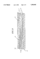
- FIG. 3 is a fragmentary longitudinal cross section of the pipe of FIG. 2 at a location away from the pipe joint;
- FIG. 4 is a side view of an end portion of the pipe of FIG. 2 in an intermediate stage of manufacture.
- a typical pipe joint has an inner member of fiber reinforced composite pipe 10 such as is conventionally made of epoxy resin reinforced with helically wound glass fibers. These are conventional pipes, albeit with a thick wall for withstanding high internal pressures.
- a high pressure pipe having a nominal inside diameter of about 20 cm may have a wall thickness of about 5 cm.
- the pipe has an external taper 11 adjacent its end.
- a half-round groove 12 extends helically along the length of the external taper. (It will be recognized that the "helical" groove in the tapered surface is not a cylindrical helix but instead has the same taper as the tapered surface 11 and a uniform depth throughout the length of the groove.)
- the external taper on the pipe fits into a coupling 13 having an internal taper 14 matching the external taper on the pipe.
- the internal taper also has a half-round groove 16 with the same pitch as the groove on the pipe.
- the outer member of the pipe joint combination is referred to as a "coupling" since that is a usual embodiment for a pipe joint.
- the "coupling” may be in any of a broad variety of pipe fittings such as valves, flange transition fittings, unions, etc.
- there are external tapers at both ends of each length of pipe and adjacent pieces of pipe are interconnected by a short coupling having two internal tapers.
- the internal and external tapers are interconnected by a round ductile key member 17, half of which lies in each of the half-round grooves on the internal and external tapers respectively.
- a suitable material for a key comprises nylon or similar ductile, relatively strong plastic.
- the key it is preferred to place the key inside the internal taper for ease of assembling and disassembling the joint.
- the external taper threading into the internal taper tends to force the key outwardly and permit free insertion of the pipe into the coupling. If a key firmly on the pipe were used, the joint could be self-locking and it could be difficult to fully tighten the joint. Likewise, the key in the coupling tends to be self releasing from the pipe when the joint is unthreaded.
- the key in the tapered pipe joint does not provide a fluid tight seal.
- a seal is provided by an adhesive elastic sealant 25 between an external sealing surface 22 on the pipe and a facing internal sealing surface 23 in the coupling.
- the sealing surfaces have the same taper at a four degree half angle as provided on the tapered surfaces forming the mechanical pipe joint.
- a pair of circumferential O-ring grooves 24 straddling the sealing surface near the end of the pipe accommodate elastomeric O-rings 26 which seal against the facing sealing surface within the coupling.
- a liquid sealant may be injected through one of a pair of passages 27 through the wall of the coupling.
- the second passage serves as an air vent and indicates when the sealant has filled the space between the sealing surfaces.
- the elastomeric O-rings retain the sealant within that space while it is liquid before curing.
- the O-rings also serve as a buffer at each end of the sealant within the annular sealing space for minimizing shear strain and keeping the sealant from shearing from the facing surfaces.
- FIGS. 2 to 4 A second embodiment of pipe joint illustrated in FIGS. 2 to 4 is described before describing functioning of the pipe joint.
- the fiber reinforced composite pipe also comprises a plurality of helically wound steel strips embedded in the wound fiber reinforcement.
- the end of such a pipe with a pipe joint is illustrated in FIG. 2 with a portion illustrated in longitudinal cross section.
- FIG. 3 is a fragmentary longitudinal cross section of the wall of the pipe significantly enlarged to show detail.
- FIG. 4 illustrates the end of the pipe in an intermediate stage in its manufacture. The drawing is as if some of the outer layers of the pipe were peeled away.
- This moiety of the pipe joint mates with a coupling (not shown) having an internal taper generally similar to the pipe coupling illustrated in FIG. 1, except that the dimensions and geometry match the external dimensions of the pipe joint moiety illustrated in FIG. 2.
- the principal portion of the length of the pipe i.e., away from the pipe joint, includes four steel strips 31.
- the steel strips are too thin to illustrate in cross section in FIG. 2 but are illustrated in the fragmentary cross section of FIG. 3.
- Each strip is from 10 to 15 cm wide and has a thickness of about 0.5 mm.
- the strips are helically wound with the edges in close proximity, typically 2 mm or less. Successive strips are staggered so that the gaps 30 between the edges of the strips are not aligned.
- a thin layer 32 of epoxy resin (about 50 gm) is between each adjacent pair of steel strips.
- FIG. 4 illustrates an end of the pipe with outer layers peeled away showing essentially the innermost layer 33 of fiber reinforced composite and the innermost layer of helically wound steel strip 31.
- the end of the steel strip is cut off at the helix angle of the strip winding so that the cut 51 edge is parallel to the end 36 of the pipe.
- the otherwise sharp point on the end of the strip is likewise cut off along an edge 52.
- a circumferential winding of glass rovings 38 is wrapped over the end portion of the strip to secure it in place while subsequent steel strips and the outer layer of fiber reinforced resin are added.
- the next overlying steel strip is helically wound with the same helix angle and the same direction of winding.
- the end of the overlying steel strip is cut off at a longer distance from the end of the pipe than the innermost layer.
- Each succeeding layer is similarly cut off at successively greater distances from the end of the pipe. This is illustrated by the widening black line in FIG. 2 which increases in width at successively greater distances from the end of the pipe.
- the scale of the drawing is too small to show the strips individually and in cross section.
- the end of the innermost strip is about 2.5 cm from the end of the pipe.
- Each successive steel strip ends about 5 cm, or half the width of the strip, away from the end of the pipe.
- the pipe joint moiety is added over these layers at the end of the pipe. Additional layers of glass fiber rovings wetted with epoxy are wound over the outside of the pipe to build up sufficient thickness to machine the finished geometry of the pipe joint. Typically the fibers are wound at a helix angle of about 700 to 800 with some outer wraps being substantially circumferential. In an exemplary embodiment with a nominal 25 cm diameter pipe, the diameter of the thickest portion of the built up windings from which the joint is made is as much as 34 cm.
- the end 41 of the added fiber reinforced composite is gradually feathered to the smaller diameter of the principal length of the pipe either in the process of winding or by machining after winding is completed. Feathering of the end minimizes stress concentrations adjacent to the joint.
- sealing surface 46 there is a sealing surface 46 near the end of the pipe beyond the end of the key groove.
- the sealing surface is between O-ring grooves 47 for retaining sealant as it is pumped into the space adjacent the sealing surfaces.
Abstract
Description
Claims (10)
Priority Applications (1)
| Application Number | Priority Date | Filing Date | Title |
|---|---|---|---|
| US08/556,447 US5785092A (en) | 1994-10-24 | 1995-11-15 | High-pressure fiber reinforced composite pipe joint |
Applications Claiming Priority (2)
| Application Number | Priority Date | Filing Date | Title |
|---|---|---|---|
| US08/327,616 US5520422A (en) | 1994-10-24 | 1994-10-24 | High-pressure fiber reinforced composite pipe joint |
| US08/556,447 US5785092A (en) | 1994-10-24 | 1995-11-15 | High-pressure fiber reinforced composite pipe joint |
Related Parent Applications (1)
| Application Number | Title | Priority Date | Filing Date |
|---|---|---|---|
| US08/327,616 Division US5520422A (en) | 1994-10-24 | 1994-10-24 | High-pressure fiber reinforced composite pipe joint |
Publications (1)
| Publication Number | Publication Date |
|---|---|
| US5785092A true US5785092A (en) | 1998-07-28 |
Family
ID=23277298
Family Applications (2)
| Application Number | Title | Priority Date | Filing Date |
|---|---|---|---|
| US08/327,616 Expired - Lifetime US5520422A (en) | 1994-10-24 | 1994-10-24 | High-pressure fiber reinforced composite pipe joint |
| US08/556,447 Expired - Lifetime US5785092A (en) | 1994-10-24 | 1995-11-15 | High-pressure fiber reinforced composite pipe joint |
Family Applications Before (1)
| Application Number | Title | Priority Date | Filing Date |
|---|---|---|---|
| US08/327,616 Expired - Lifetime US5520422A (en) | 1994-10-24 | 1994-10-24 | High-pressure fiber reinforced composite pipe joint |
Country Status (7)
| Country | Link |
|---|---|
| US (2) | US5520422A (en) |
| EP (3) | EP0792429B1 (en) |
| CN (1) | CN1053036C (en) |
| DE (2) | DE69525174T2 (en) |
| MX (1) | MX9703006A (en) |
| MY (1) | MY114006A (en) |
| WO (1) | WO1996012911A1 (en) |
Cited By (17)
| Publication number | Priority date | Publication date | Assignee | Title |
|---|---|---|---|---|
| US6363975B1 (en) * | 1998-11-17 | 2002-04-02 | Ameron International Corporation | Bonding of steel strips in steel strip laminate pipe |
| US20030122373A1 (en) * | 2001-10-22 | 2003-07-03 | Hirth David Eugene | Locking arrangement for a threaded connector |
| US6588969B2 (en) * | 2001-08-13 | 2003-07-08 | The Aerospace Corporation | Adhesive strengthening embedded micromachines |
| US20030178079A1 (en) * | 2002-03-22 | 2003-09-25 | Friedrich Ralph S. | Sewer pipe section |
| US20060049631A1 (en) * | 2002-04-26 | 2006-03-09 | Pieter Tolhoek | Pipe connection for pipe pieces made of plastic |
| GB2439148A (en) * | 2006-06-16 | 2007-12-19 | Wellstream Int Ltd | Pipe armour wires support in terminating collar |
| EP2102610A2 (en) * | 2007-01-10 | 2009-09-23 | Tyco Fire Products LP | Methods and systems for detecting and sealing dry fit connections in a piping assembly |
| US7757718B1 (en) | 2007-06-20 | 2010-07-20 | Bruce Mark H | Polymer reinforcement for a clay pipe joint |
| CN101915062A (en) * | 2010-07-20 | 2010-12-15 | 中国矿业大学(北京) | Glass reinforced plastic sleeve used for coal bed gas well |
| US20110041944A1 (en) * | 2009-08-21 | 2011-02-24 | Titeflex Corporation | Energy dissipative tubes and methods of fabricating and installing the same |
| US20110132486A1 (en) * | 2009-12-07 | 2011-06-09 | General Plastics & Composites LP | High Strength Thread for Tubular Composites |
| US8899274B1 (en) | 2014-02-17 | 2014-12-02 | Universal Fiberglass, LLC | Fiberglass flanged pipe and method of making same |
| US9347591B2 (en) | 2011-08-12 | 2016-05-24 | Chevron U.S.A. Inc. | Static dissipation in composite structural components |
| US11703170B2 (en) | 2018-06-29 | 2023-07-18 | Varco I/P, Inc. | High pressure composite pipe joining system |
| US11754215B2 (en) | 2020-07-20 | 2023-09-12 | Saudi Arabian Oil Company | Apparatus and method for friction welding of reinforced thermosetting resin pipe joints |
| US11761571B2 (en) | 2020-07-20 | 2023-09-19 | Saudi Arabian Oil Company | Apparatus and method for electrofusion welding of reinforced thermosetting resin pipe joints |
| US11794418B2 (en) | 2020-07-20 | 2023-10-24 | Saudi Arabian Oil Company | Apparatus and method for threaded-welded reinforced thermosetting resin pipe joints |
Families Citing this family (64)
| Publication number | Priority date | Publication date | Assignee | Title |
|---|---|---|---|---|
| US5984369A (en) * | 1997-06-16 | 1999-11-16 | Cordant Technologies Inc. | Assembly including tubular bodies and mated with a compression loaded adhesive bond |
| US6517080B1 (en) | 1999-07-19 | 2003-02-11 | Caterpillar Inc | Seal material having anisotropic properties |
| US6620475B1 (en) | 2000-08-10 | 2003-09-16 | Hydril Company | Structure for wound fiber reinforced plastic tubing and method for making |
| US6361080B1 (en) | 2000-08-23 | 2002-03-26 | Hydril Company | Method for attaching an ANSI stub-end flanged connector to a composite tubular member |
| EP1359359A1 (en) * | 2002-04-29 | 2003-11-05 | Shell Internationale Researchmaatschappij B.V. | Screw thread connector seal |
| US6685236B2 (en) * | 2002-06-28 | 2004-02-03 | Weatherford/Lamb, Inc. | Helically wound expandable tubular insert |
| GB0215668D0 (en) * | 2002-07-06 | 2002-08-14 | Weatherford Lamb | Coupling tubulars |
| GB0221220D0 (en) * | 2002-09-13 | 2002-10-23 | Weatherford Lamb | Expanding coupling |
| GB0221585D0 (en) * | 2002-09-17 | 2002-10-23 | Weatherford Lamb | Tubing connection arrangement |
| GB0222321D0 (en) * | 2002-09-25 | 2002-10-30 | Weatherford Lamb | Expandable connection |
| US6981547B2 (en) * | 2002-12-06 | 2006-01-03 | Weatherford/Lamb, Inc. | Wire lock expandable connection |
| US7887103B2 (en) | 2003-05-22 | 2011-02-15 | Watherford/Lamb, Inc. | Energizing seal for expandable connections |
| US7025135B2 (en) * | 2003-05-22 | 2006-04-11 | Weatherford/Lamb, Inc. | Thread integrity feature for expandable connections |
| GB0311721D0 (en) * | 2003-05-22 | 2003-06-25 | Weatherford Lamb | Tubing connector |
| US20050100414A1 (en) * | 2003-11-07 | 2005-05-12 | Conocophillips Company | Composite riser with integrity monitoring apparatus and method |
| US7360552B2 (en) * | 2004-04-23 | 2008-04-22 | Dow Global Technologies Inc. | Injectable structural adhesive |
| JP2009500577A (en) * | 2005-07-03 | 2009-01-08 | ウィデー・ベスローテン・フェンノートシャップ | Two pipe fittings |
| US9156087B2 (en) | 2007-06-21 | 2015-10-13 | Molten Metal Equipment Innovations, Llc | Molten metal transfer system and rotor |
| US8337746B2 (en) | 2007-06-21 | 2012-12-25 | Cooper Paul V | Transferring molten metal from one structure to another |
| FR2930587A1 (en) * | 2008-04-24 | 2009-10-30 | Saipem S A Sa | BACKFLY-SURFACE LINK INSTALLATION OF A RIGID CONDUIT WITH A POSITIVE FLOATABLE FLEXIBLE DRIVE AND A TRANSITIONAL PART OF INERTIA |
| DE102008027382A1 (en) * | 2008-06-09 | 2009-12-17 | Uponor Innovation Ab | Press fitting for a pipe, in particular plastic pipe or plastic-metal composite pipe |
| WO2010121383A1 (en) * | 2009-04-20 | 2010-10-28 | Flexpipe Systems Inc. | Metal cord reinforced flexible pipe |
| US9556994B2 (en) | 2009-06-30 | 2017-01-31 | Antelope Oil Tool & Mfg. Co. | Wrap-around band and sleeve attachment apparatus for an oilfield tubular |
| US8524146B2 (en) * | 2009-08-07 | 2013-09-03 | Paul V. Cooper | Rotary degassers and components therefor |
| DE102009029657A1 (en) * | 2009-09-22 | 2011-03-24 | Deere & Company, Moline | Node element for a vehicle frame structure |
| US20110233126A1 (en) * | 2010-03-25 | 2011-09-29 | Prouty Warren C | Reverse Osmosis Pressure Vessel End Cap Assembly |
| CN102465693A (en) * | 2010-10-29 | 2012-05-23 | 乌兰察布新奥气化采煤技术有限公司 | Underground coal gasification bored well body structure and construction method thereof |
| CN102338255A (en) * | 2011-09-19 | 2012-02-01 | 江苏双腾管业有限公司 | Fiber reinforced electric fusing pipe fitting |
| US20130087245A1 (en) * | 2011-10-07 | 2013-04-11 | Chrysler Group Llc | Cooling system filling air |
| AR088888A1 (en) | 2011-11-16 | 2014-07-16 | Flexpipe Systems Inc | CONNECTION FOR THERMOPLASTIC PIPES, ASSEMBLY AND METHOD |
| AU2012339553B2 (en) | 2011-11-16 | 2016-05-12 | Flexpipe Systems Inc. | Flexible reinforced pipe and reinforcement tape |
| US10760719B2 (en) * | 2011-11-28 | 2020-09-01 | Future Pipe Industries Group Limited | Fiberglass pipe jointing methods and systems |
| EP2815164B1 (en) | 2012-02-17 | 2019-11-27 | CORE Linepipe Inc. | Pipe, pipe connection and pipeline system |
| CA2809601A1 (en) * | 2012-03-16 | 2013-09-16 | J-M Manufacturing Company, Inc. | Pressure-rated spline joint |
| DE102013008810B4 (en) | 2012-06-13 | 2016-06-23 | Ralph Funck | Force transmission in fiber composite pipes |
| CN102720891B (en) * | 2012-06-28 | 2014-07-02 | 天津大学 | Submarine pipeline buckle arrestor with spiral eye plates and fixation method for submarine pipeline buckle arrestor |
| CN102809051B (en) * | 2012-08-07 | 2015-05-06 | 西安康本材料有限公司 | Composite material pipe applicable to spiral key connection and producing method for composite material pipe |
| US9797257B2 (en) | 2012-12-10 | 2017-10-24 | General Electric Company | Attachment of composite article |
| US9777579B2 (en) | 2012-12-10 | 2017-10-03 | General Electric Company | Attachment of composite article |
| US9097602B2 (en) | 2013-01-23 | 2015-08-04 | Lawrence Livermore National Security, Llc | Systems and methods for determining strength of cylindrical structures by internal pressure loading |
| US9903383B2 (en) | 2013-03-13 | 2018-02-27 | Molten Metal Equipment Innovations, Llc | Molten metal rotor with hardened top |
| US20150047907A1 (en) * | 2013-08-17 | 2015-02-19 | Antelope Oil Tool & Mfg. Co., Llc | Wrap-around band tool connector and method of forming |
| WO2015026669A1 (en) | 2013-08-17 | 2015-02-26 | Antelope Oil Tools & Mfg. Co., Llc | Multi-vane centralizer and method of forming |
| DE202013103804U1 (en) * | 2013-08-22 | 2014-11-24 | Richard Weinhold | Coupling arrangement, in particular pipe coupling |
| CN103615604B (en) * | 2013-12-13 | 2016-03-02 | 欧阳杰 | A kind of glass fibre reinforced plastics and steel composite pipe fitting and manufacture method thereof |
| CN103727325A (en) * | 2013-12-26 | 2014-04-16 | 昆明普尔顿环保科技股份有限公司 | High-performance low-cost spiral corrugated pipe reinforced by steel strips |
| US10465688B2 (en) | 2014-07-02 | 2019-11-05 | Molten Metal Equipment Innovations, Llc | Coupling and rotor shaft for molten metal devices |
| EP3025846B1 (en) * | 2014-11-28 | 2019-11-13 | Crompton Technology Group Limited | Composite tension/compression strut |
| EP3034561B1 (en) * | 2014-12-19 | 2019-02-06 | NKT HV Cables GmbH | A method of manufacturing a high-voltage DC cable joint, and a high-voltage DC cable joint. |
| US10947980B2 (en) | 2015-02-02 | 2021-03-16 | Molten Metal Equipment Innovations, Llc | Molten metal rotor with hardened blade tips |
| KR102342659B1 (en) * | 2015-06-02 | 2021-12-23 | 엔케이티 에이치브이 케이블스 게엠베하 | A rigid joint assembly |
| CN105020521A (en) * | 2015-07-03 | 2015-11-04 | 天津鑫坤泰预应力专业技术有限公司 | Sealing joint for connecting bamboo-like prestress flat port plastic pipes and having latches for locking |
| CN105019561B (en) * | 2015-07-30 | 2017-05-03 | 中国人民解放军理工大学 | Meshing connector used for connecting composite materials |
| US10267314B2 (en) | 2016-01-13 | 2019-04-23 | Molten Metal Equipment Innovations, Llc | Tensioned support shaft and other molten metal devices |
| EP3203094B1 (en) * | 2016-02-04 | 2021-09-22 | Crompton Technology Group Limited | Composite shaft joint |
| RU173685U1 (en) * | 2016-08-25 | 2017-09-05 | Сергей Алексеевич Волков | FIBERGLASS PIPE WITH SIDE ENCLOSURE |
| US9988093B2 (en) * | 2016-09-28 | 2018-06-05 | Ford Global Technologies, Llc | Exoskeleton vehicle upper body structure |
| US11149747B2 (en) | 2017-11-17 | 2021-10-19 | Molten Metal Equipment Innovations, Llc | Tensioned support post and other molten metal devices |
| US11174969B2 (en) * | 2019-01-16 | 2021-11-16 | The Boeing Company | Threaded connection of a duct |
| US11471938B2 (en) | 2019-05-17 | 2022-10-18 | Molten Metal Equipment Innovations, Llc | Smart molten metal pump |
| NL2023274B1 (en) * | 2019-06-07 | 2021-01-11 | Itrec Bv | Tubular with screw thread |
| US20220196196A1 (en) * | 2020-12-17 | 2022-06-23 | Saudi Arabian Oil Company | Apparatus and method for bonding tie layers on reinforced thermosetting resin laminates for use in welding thermoset composite pipe joints |
| US11873845B2 (en) | 2021-05-28 | 2024-01-16 | Molten Metal Equipment Innovations, Llc | Molten metal transfer device |
| CN115923165B (en) * | 2022-09-30 | 2023-12-01 | 中国人民解放军陆军工程大学 | Extrusion-molded composite material and metal piece thread-shaped connecting structure and method |
Citations (25)
| Publication number | Priority date | Publication date | Assignee | Title |
|---|---|---|---|---|
| US133219A (en) * | 1872-11-19 | Improvedent in vulcanized india-rubber hose | ||
| US1314670A (en) * | 1919-09-02 | Reinforced hard-rubber pipe | ||
| US1394300A (en) * | 1920-03-22 | 1921-10-18 | Goodrich Co B F | Reinforced-rubber article |
| US1831724A (en) * | 1929-11-07 | 1931-11-10 | Thermoid Rubber Company | Armored hose |
| US2341670A (en) * | 1942-01-17 | 1944-02-15 | Hughes Tool Co | Pipe and tool joint connection |
| US2418418A (en) * | 1943-12-11 | 1947-04-01 | United Aircraft Corp | Aluminum propeller blade with steel shank |
| US2640501A (en) * | 1946-12-24 | 1953-06-02 | Int Standard Electric Corp | Tube and its manufacture |
| GB747194A (en) * | 1953-09-02 | 1956-03-28 | Ici Ltd | Improvements in or relating to tubes or the like and to the manufacture thereof |
| US2911236A (en) * | 1956-11-09 | 1959-11-03 | Kleber Colombes | Semi-flexible pipes and pipe connecting means |
| GB898194A (en) * | 1954-12-22 | 1962-06-06 | Ici Ltd | Rocket motor casings |
| AU6726365A (en) * | 1965-11-30 | 1967-06-01 | Cen-Viro Pipe Corporation | Pipe joint of synthetic plastic concrete |
| US3559693A (en) * | 1967-05-05 | 1971-02-02 | Inst Francais Du Petrole | Windable flexible shaft capable of withstanding high tractive forces and torsional stresses |
| US3790438A (en) * | 1971-12-28 | 1974-02-05 | Monsanto Co | Ribbon-reinforced composites |
| US3814138A (en) * | 1972-10-18 | 1974-06-04 | Weatherhead Co | Hose construction |
| GB1407913A (en) * | 1972-10-12 | 1975-10-01 | Battelle Memorial Institute | Rigid tubular bodies |
| AU8024475A (en) * | 1974-04-29 | 1975-12-04 | Interface Corporation | Prestressed concrete pipes |
| US4351364A (en) * | 1979-11-05 | 1982-09-28 | Dunlop Limited | Steel reinforced pipe |
| EP0157971A1 (en) * | 1984-04-06 | 1985-10-16 | John Tiberio | Pipe line coupling |
| US4647080A (en) * | 1985-02-04 | 1987-03-03 | Price Brothers Company | Pipe joint |
| US4943094A (en) * | 1988-09-30 | 1990-07-24 | Centron Corporation | Threaded pin and box construction for composite tubulars |
| US5072759A (en) * | 1990-01-22 | 1991-12-17 | Teleflex Incorporated | Reverse stranded conduit |
| US5106130A (en) * | 1988-06-28 | 1992-04-21 | A. O. Smith Corporation | Composite thread coupling for reinforced pipe |
| US5279596A (en) * | 1990-07-27 | 1994-01-18 | Cordis Corporation | Intravascular catheter with kink resistant tip |
| WO1994013993A1 (en) * | 1992-12-08 | 1994-06-23 | Royal Ordnance Plc | Pipe coupling |
| US5341849A (en) * | 1991-11-05 | 1994-08-30 | Markel Corporation | Fuel system conduit |
Family Cites Families (21)
| Publication number | Priority date | Publication date | Assignee | Title |
|---|---|---|---|---|
| US170473A (en) * | 1875-11-30 | Improvement in the art of coupling sections of pipe or tubing | ||
| US506484A (en) * | 1893-10-10 | Robert ewing | ||
| US10877A (en) * | 1854-05-09 | Beehive | ||
| US3062568A (en) * | 1959-10-20 | 1962-11-06 | Alf S Andresen | Safety screw thread arrangement |
| US3104583A (en) * | 1960-10-31 | 1963-09-24 | Autoclave Eng Inc | Screw connection having coil spring thread means |
| US3396994A (en) * | 1965-11-13 | 1968-08-13 | Ito Tsunehiko | Hose coupling for reinforced flexible hose |
| US3353563A (en) * | 1966-04-01 | 1967-11-21 | Walter C Hutton | Insulated joint |
| US3427047A (en) * | 1966-11-30 | 1969-02-11 | Nasa | Tubular coupling having frangible connecting means |
| AT297424B (en) * | 1968-07-22 | 1972-03-27 | Industriebedarf Ges M B H | Pipe socket connection |
| GB1293371A (en) * | 1969-03-31 | 1972-10-18 | Redland Pipes Ltd | Method of, and apparatus for, connecting pipes end-to-end |
| AT329937B (en) * | 1973-01-15 | 1976-06-10 | Freiberg Brennstoffinst | PIPE CONNECTION, ESPECIALLY FOR BURNING THERMO-PLASTIC PIPES WITH LARGE NOMINAL SIZES AND HIGH OPERATING PRESSURES |
| DE2706649A1 (en) * | 1977-02-23 | 1978-08-24 | Pilgrim Eng Dev | PIPE JOINT AND METHOD OF MANUFACTURING THE SAME |
| US4174124A (en) * | 1977-03-24 | 1979-11-13 | Pipeline Seal and Insulation Co. Ltd. | Pipe joints and connectors therefor |
| US4491351A (en) * | 1982-02-08 | 1985-01-01 | Armco Inc. | Helical coil stab-in connector |
| JPS63293384A (en) * | 1987-05-27 | 1988-11-30 | 住友金属工業株式会社 | Frp pipe with screw coupling |
| US5213379A (en) * | 1989-11-21 | 1993-05-25 | Sumitomo Metal Industries, Ltd. | Frp pipe with threaded end joint section |
| NL9001384A (en) * | 1990-06-18 | 1992-01-16 | Wavin Bv | MULTILAYER TUBE, PIPE FROM MULTIPLE OF SUCH TUBES AND METHOD FOR CONNECTING GAS AND LIQUID-TIGHT OF TWO SUCH TUBES. |
| US5233737A (en) * | 1991-10-25 | 1993-08-10 | Hercules Incorporated | Filament wound threaded tube connection |
| US5398975A (en) * | 1992-03-13 | 1995-03-21 | Centron Corporation | Composite threaded pipe connectors and method |
| US5350202A (en) * | 1992-08-05 | 1994-09-27 | Smith Fiberglass Products Inc. | Method and apparatus for attaching lengths of fiberglass reinforced plastic pipe |
| ES2112512T3 (en) * | 1992-12-08 | 1998-04-01 | Royal Ordnance Plc | PIPE CONSTRUCTION. |
-
1994
- 1994-10-24 US US08/327,616 patent/US5520422A/en not_active Expired - Lifetime
-
1995
- 1995-10-18 MY MYPI95003128A patent/MY114006A/en unknown
- 1995-10-24 DE DE69525174T patent/DE69525174T2/en not_active Expired - Lifetime
- 1995-10-24 MX MX9703006A patent/MX9703006A/en unknown
- 1995-10-24 WO PCT/US1995/013698 patent/WO1996012911A1/en active IP Right Grant
- 1995-10-24 EP EP95942385A patent/EP0792429B1/en not_active Expired - Lifetime
- 1995-10-24 EP EP99203114A patent/EP0978677B1/en not_active Expired - Lifetime
- 1995-10-24 DE DE69532728T patent/DE69532728T2/en not_active Expired - Lifetime
- 1995-10-24 CN CN95197061A patent/CN1053036C/en not_active Expired - Lifetime
- 1995-10-24 EP EP99203115A patent/EP0972980A3/en not_active Withdrawn
- 1995-11-15 US US08/556,447 patent/US5785092A/en not_active Expired - Lifetime
Patent Citations (26)
| Publication number | Priority date | Publication date | Assignee | Title |
|---|---|---|---|---|
| US133219A (en) * | 1872-11-19 | Improvedent in vulcanized india-rubber hose | ||
| US1314670A (en) * | 1919-09-02 | Reinforced hard-rubber pipe | ||
| US1394300A (en) * | 1920-03-22 | 1921-10-18 | Goodrich Co B F | Reinforced-rubber article |
| US1831724A (en) * | 1929-11-07 | 1931-11-10 | Thermoid Rubber Company | Armored hose |
| US2341670A (en) * | 1942-01-17 | 1944-02-15 | Hughes Tool Co | Pipe and tool joint connection |
| US2418418A (en) * | 1943-12-11 | 1947-04-01 | United Aircraft Corp | Aluminum propeller blade with steel shank |
| US2640501A (en) * | 1946-12-24 | 1953-06-02 | Int Standard Electric Corp | Tube and its manufacture |
| GB747194A (en) * | 1953-09-02 | 1956-03-28 | Ici Ltd | Improvements in or relating to tubes or the like and to the manufacture thereof |
| GB898194A (en) * | 1954-12-22 | 1962-06-06 | Ici Ltd | Rocket motor casings |
| US2911236A (en) * | 1956-11-09 | 1959-11-03 | Kleber Colombes | Semi-flexible pipes and pipe connecting means |
| AU6726365A (en) * | 1965-11-30 | 1967-06-01 | Cen-Viro Pipe Corporation | Pipe joint of synthetic plastic concrete |
| US3559693A (en) * | 1967-05-05 | 1971-02-02 | Inst Francais Du Petrole | Windable flexible shaft capable of withstanding high tractive forces and torsional stresses |
| US3790438A (en) * | 1971-12-28 | 1974-02-05 | Monsanto Co | Ribbon-reinforced composites |
| US4657049A (en) * | 1972-10-12 | 1987-04-14 | Georges Fourty | Tubular body composed of reinforced thermosetting polymer |
| GB1407913A (en) * | 1972-10-12 | 1975-10-01 | Battelle Memorial Institute | Rigid tubular bodies |
| US3814138A (en) * | 1972-10-18 | 1974-06-04 | Weatherhead Co | Hose construction |
| AU8024475A (en) * | 1974-04-29 | 1975-12-04 | Interface Corporation | Prestressed concrete pipes |
| US4351364A (en) * | 1979-11-05 | 1982-09-28 | Dunlop Limited | Steel reinforced pipe |
| EP0157971A1 (en) * | 1984-04-06 | 1985-10-16 | John Tiberio | Pipe line coupling |
| US4647080A (en) * | 1985-02-04 | 1987-03-03 | Price Brothers Company | Pipe joint |
| US5106130A (en) * | 1988-06-28 | 1992-04-21 | A. O. Smith Corporation | Composite thread coupling for reinforced pipe |
| US4943094A (en) * | 1988-09-30 | 1990-07-24 | Centron Corporation | Threaded pin and box construction for composite tubulars |
| US5072759A (en) * | 1990-01-22 | 1991-12-17 | Teleflex Incorporated | Reverse stranded conduit |
| US5279596A (en) * | 1990-07-27 | 1994-01-18 | Cordis Corporation | Intravascular catheter with kink resistant tip |
| US5341849A (en) * | 1991-11-05 | 1994-08-30 | Markel Corporation | Fuel system conduit |
| WO1994013993A1 (en) * | 1992-12-08 | 1994-06-23 | Royal Ordnance Plc | Pipe coupling |
Cited By (28)
| Publication number | Priority date | Publication date | Assignee | Title |
|---|---|---|---|---|
| US6363975B1 (en) * | 1998-11-17 | 2002-04-02 | Ameron International Corporation | Bonding of steel strips in steel strip laminate pipe |
| US6588969B2 (en) * | 2001-08-13 | 2003-07-08 | The Aerospace Corporation | Adhesive strengthening embedded micromachines |
| US20030122373A1 (en) * | 2001-10-22 | 2003-07-03 | Hirth David Eugene | Locking arrangement for a threaded connector |
| US6908121B2 (en) * | 2001-10-22 | 2005-06-21 | Weatherford/Lamb, Inc. | Locking arrangement for a threaded connector |
| US20030178079A1 (en) * | 2002-03-22 | 2003-09-25 | Friedrich Ralph S. | Sewer pipe section |
| US6920900B2 (en) * | 2002-03-22 | 2005-07-26 | Ameron International Corporation | Sewer pipe section |
| US20060049631A1 (en) * | 2002-04-26 | 2006-03-09 | Pieter Tolhoek | Pipe connection for pipe pieces made of plastic |
| GB2439148A (en) * | 2006-06-16 | 2007-12-19 | Wellstream Int Ltd | Pipe armour wires support in terminating collar |
| US20090322077A1 (en) * | 2006-06-16 | 2009-12-31 | Tony Eccleston | Radius control |
| US9534719B2 (en) | 2006-06-16 | 2017-01-03 | Ge Oil & Gas Uk Limited | Flexible pipe end fitting |
| EP2102610A2 (en) * | 2007-01-10 | 2009-09-23 | Tyco Fire Products LP | Methods and systems for detecting and sealing dry fit connections in a piping assembly |
| EP2102610A4 (en) * | 2007-01-10 | 2012-11-28 | Tyco Fire Products Lp | Methods and systems for detecting and sealing dry fit connections in a piping assembly |
| US7757718B1 (en) | 2007-06-20 | 2010-07-20 | Bruce Mark H | Polymer reinforcement for a clay pipe joint |
| EP2467916A1 (en) * | 2009-08-21 | 2012-06-27 | Titeflex Corporation | Energy dissipative tubes, sealing devices, and methods of fabricating and installing the same |
| US20110041944A1 (en) * | 2009-08-21 | 2011-02-24 | Titeflex Corporation | Energy dissipative tubes and methods of fabricating and installing the same |
| EP2467916A4 (en) * | 2009-08-21 | 2014-06-04 | Titeflex Corp | Energy dissipative tubes, sealing devices, and methods of fabricating and installing the same |
| US10293440B2 (en) | 2009-08-21 | 2019-05-21 | Titeflex Corporation | Methods of forming energy-dissipative tubes |
| US9249904B2 (en) | 2009-08-21 | 2016-02-02 | Titeflex Corporation | Energy dissipative tubes and methods of fabricating and installing the same |
| US9445486B2 (en) | 2009-08-21 | 2016-09-13 | Titeflex Corporation | Energy dissipative tubes |
| US8919387B2 (en) * | 2009-12-07 | 2014-12-30 | General Plastics & Composites, L.P. | High strength thread for tubular composites |
| US20110132486A1 (en) * | 2009-12-07 | 2011-06-09 | General Plastics & Composites LP | High Strength Thread for Tubular Composites |
| CN101915062A (en) * | 2010-07-20 | 2010-12-15 | 中国矿业大学(北京) | Glass reinforced plastic sleeve used for coal bed gas well |
| US9347591B2 (en) | 2011-08-12 | 2016-05-24 | Chevron U.S.A. Inc. | Static dissipation in composite structural components |
| US8899274B1 (en) | 2014-02-17 | 2014-12-02 | Universal Fiberglass, LLC | Fiberglass flanged pipe and method of making same |
| US11703170B2 (en) | 2018-06-29 | 2023-07-18 | Varco I/P, Inc. | High pressure composite pipe joining system |
| US11754215B2 (en) | 2020-07-20 | 2023-09-12 | Saudi Arabian Oil Company | Apparatus and method for friction welding of reinforced thermosetting resin pipe joints |
| US11761571B2 (en) | 2020-07-20 | 2023-09-19 | Saudi Arabian Oil Company | Apparatus and method for electrofusion welding of reinforced thermosetting resin pipe joints |
| US11794418B2 (en) | 2020-07-20 | 2023-10-24 | Saudi Arabian Oil Company | Apparatus and method for threaded-welded reinforced thermosetting resin pipe joints |
Also Published As
| Publication number | Publication date |
|---|---|
| DE69532728T2 (en) | 2005-01-20 |
| EP0792429A4 (en) | 1999-04-21 |
| DE69525174T2 (en) | 2002-09-26 |
| EP0978677A3 (en) | 2000-04-12 |
| CN1171149A (en) | 1998-01-21 |
| WO1996012911A1 (en) | 1996-05-02 |
| DE69532728D1 (en) | 2004-04-22 |
| EP0978677B1 (en) | 2004-03-17 |
| DE69525174D1 (en) | 2002-03-14 |
| MX9703006A (en) | 1997-10-31 |
| EP0792429A1 (en) | 1997-09-03 |
| US5520422A (en) | 1996-05-28 |
| EP0978677A2 (en) | 2000-02-09 |
| MY114006A (en) | 2002-07-31 |
| EP0792429B1 (en) | 2002-01-23 |
| EP0972980A3 (en) | 2000-04-12 |
| EP0972980A2 (en) | 2000-01-19 |
| CN1053036C (en) | 2000-05-31 |
Similar Documents
| Publication | Publication Date | Title |
|---|---|---|
| US5785092A (en) | High-pressure fiber reinforced composite pipe joint | |
| US6273142B1 (en) | Flexible pipe with an associated end-fitting | |
| US5895079A (en) | Threaded connections utilizing composite materials | |
| US5636878A (en) | Pipe coupling | |
| US9534719B2 (en) | Flexible pipe end fitting | |
| US10451206B2 (en) | Connection end-piece of a flexible pipe for transporting fluid and associated method | |
| US4398754A (en) | Electrically insulated pipe coupling and method for making the same | |
| US8104797B2 (en) | Extended collar | |
| US5186500A (en) | Fiberglass tubular coupling with liner | |
| US6405762B1 (en) | Composite pipe assembly and method for preparing the same | |
| EA010127B1 (en) | Improvements in tubular bodies and methods of forming same | |
| US2944839A (en) | Coupling for reinforced plastic pipe | |
| EP1206659B1 (en) | Securing of reinforcement wires to an end termination of a pipeline or a cable, and uses of the end termination | |
| US20220268389A1 (en) | Pre-tightening force repairing method, repairing method involving combination of pre-tightening force and clamp, and repaired pipeline | |
| US7303213B2 (en) | Flexible pipe connected to an end fitting | |
| US4252349A (en) | High pressure plastic pipe coupling | |
| EP0625252B1 (en) | Pipe coupling | |
| US6920900B2 (en) | Sewer pipe section | |
| CA2203643C (en) | High-pressure fiber reinforced composite pipe joint | |
| KR930000500B1 (en) | Oilwell tubing connection | |
| CN213743279U (en) | Special joint for adhesive composite flexible pipe | |
| CN209800880U (en) | Threaded connection enhanced composite pipe | |
| US20230392729A1 (en) | End Fitting for a Pipe and Associated Methods | |
| EP0163957B1 (en) | Corrosion-resistant pipe coupling structures | |
| RU2191947C1 (en) | Pipe connecting device |
Legal Events
| Date | Code | Title | Description |
|---|---|---|---|
| AS | Assignment |
Owner name: AMERON INTERNATIONAL CORPORATION, CALIFORNIA Free format text: CHANGE OF NAME;ASSIGNOR:AMERON, INC.;REEL/FRAME:007985/0592 Effective date: 19960430 |
|
| STCF | Information on status: patent grant |
Free format text: PATENTED CASE |
|
| CC | Certificate of correction | ||
| FPAY | Fee payment |
Year of fee payment: 4 |
|
| AS | Assignment |
Owner name: BANK OF AMERICA, N.A. AS COLLATERAL AGENT, CALIFOR Free format text: NOTICE OF GRANT OF SECURITY INTEREST;ASSIGNOR:AMERON INTERNATIONAL CORPORATION;REEL/FRAME:014007/0001 Effective date: 20030124 |
|
| AS | Assignment |
Owner name: BANK OF AMERICA, N.A., AS COLLATERAL AGENT, CALIFO Free format text: NOTICE OF GRANT OF SECURITY INTEREST;ASSIGNOR:AMERON INTERNATIONAL CORPORATION;REEL/FRAME:014499/0658 Effective date: 20030124 |
|
| FPAY | Fee payment |
Year of fee payment: 8 |
|
| AS | Assignment |
Owner name: AMERON INTERNATIONAL CORPORATION, CALIFORNIA Free format text: RELEASE BY SECURED PARTY;ASSIGNOR:BANK OF AMERICA, N.A.;REEL/FRAME:018194/0219 Effective date: 20060801 |
|
| AS | Assignment |
Owner name: AMERON, INC., CALIFORNIA Free format text: ASSIGNMENT OF ASSIGNORS INTEREST;ASSIGNORS:FRIEDRICH, RALPH;KUO, MING;SMYTH, KEVIN;REEL/FRAME:023129/0788 Effective date: 19941019 |
|
| AS | Assignment |
Owner name: BANK OF AMERICA, N.A., AS ADMINISTRATIVE AGENT, CA Free format text: NOTICE OF GRANT OF SECURITY INTEREST IN PATENTS;ASSIGNOR:AMERON INTERNATIONAL CORPORATION;REEL/FRAME:023163/0904 Effective date: 20030124 |
|
| FPAY | Fee payment |
Year of fee payment: 12 |
|
| AS | Assignment |
Owner name: BANK OF AMERICA, N.A, NORTH CAROLINA Free format text: CORRECTIVE ASSIGNMENT TO CORRECT THE RECORDATION OF RELEASE OF SECURITY INTEREST. SECURITY INTEREST WAS NOT TO BE RELEASED AGAINST THIS REGISTRATION AS PREVIOUSLY RECORDED ON REEL 018194 FRAME 0219;ASSIGNOR:AMERON INTERNATIONAL COORPORATION;REEL/FRAME:023607/0388 Effective date: 20060801 |
|
| AS | Assignment |
Owner name: AMERON INTERNATIONAL CORPORATION, CALIFORNIA Free format text: RELEASE BY SECURED PARTY;ASSIGNOR:BANK OF AMERICA, N.A., AS ADMINISTRATIVE AGENT;REEL/FRAME:027034/0718 Effective date: 20111005 |