US5777662A - Ingress/egress management system - Google Patents
Ingress/egress management system Download PDFInfo
- Publication number
- US5777662A US5777662A US08/703,773 US70377396A US5777662A US 5777662 A US5777662 A US 5777662A US 70377396 A US70377396 A US 70377396A US 5777662 A US5777662 A US 5777662A
- Authority
- US
- United States
- Prior art keywords
- coaxial cable
- egress
- ingress
- leaks
- headend
- Prior art date
- Legal status (The legal status is an assumption and is not a legal conclusion. Google has not performed a legal analysis and makes no representation as to the accuracy of the status listed.)
- Expired - Lifetime
Links
Images


Classifications
-
- H—ELECTRICITY
- H04—ELECTRIC COMMUNICATION TECHNIQUE
- H04H—BROADCAST COMMUNICATION
- H04H20/00—Arrangements for broadcast or for distribution combined with broadcast
- H04H20/12—Arrangements for observation, testing or troubleshooting
-
- H—ELECTRICITY
- H04—ELECTRIC COMMUNICATION TECHNIQUE
- H04N—PICTORIAL COMMUNICATION, e.g. TELEVISION
- H04N17/00—Diagnosis, testing or measuring for television systems or their details
-
- G—PHYSICS
- G01—MEASURING; TESTING
- G01S—RADIO DIRECTION-FINDING; RADIO NAVIGATION; DETERMINING DISTANCE OR VELOCITY BY USE OF RADIO WAVES; LOCATING OR PRESENCE-DETECTING BY USE OF THE REFLECTION OR RERADIATION OF RADIO WAVES; ANALOGOUS ARRANGEMENTS USING OTHER WAVES
- G01S19/00—Satellite radio beacon positioning systems; Determining position, velocity or attitude using signals transmitted by such systems
- G01S19/01—Satellite radio beacon positioning systems transmitting time-stamped messages, e.g. GPS [Global Positioning System], GLONASS [Global Orbiting Navigation Satellite System] or GALILEO
- G01S19/13—Receivers
- G01S19/14—Receivers specially adapted for specific applications
-
- H—ELECTRICITY
- H04—ELECTRIC COMMUNICATION TECHNIQUE
- H04H—BROADCAST COMMUNICATION
- H04H20/00—Arrangements for broadcast or for distribution combined with broadcast
- H04H20/65—Arrangements characterised by transmission systems for broadcast
- H04H20/76—Wired systems
- H04H20/77—Wired systems using carrier waves
- H04H20/78—CATV [Community Antenna Television] systems
Definitions
- the present invention generally relates to monitoring the radio frequency (RF) leaks in a coaxial cable communication system, such as a cable television (CATV) plant, and more particularly, to a management system that allows monitoring of the ingress and egress of RF energy in a coaxial plant and presenting management system information in a format that allows the best utilization of system maintenance resources.
- RF radio frequency
- the Shimp RF leak detector detects RF leaks by transmitting a unique signal at the headend of the coaxial plant and, using a very narrow band receiver, detects the unique signal at locations of defects in the shielding.
- RF leak detection is combined with a global positioning system (GPS) and a computer control unit to measure RF signal strength, while maintaining the corrected distance between the vehicle and the source of the leak. This data is stored for later analysis.
- GPS global positioning system
- RF leak detectors have been a useful tool in the maintenance of coaxial cable plants; however, the demand for a greater number of channels, in both basic and premium services, and the advent of digital transmission have made it necessary to advance the state of the art in RF leak detectors for coaxial cable plants.
- the demand for a greater number of channels places a premium on the bandwidth requirements of the cable system, making it impractical to provide a unique signal dedicated for the detection of RF leaks, as in the Shimp RF leak detector.
- Digital transmission also places a premium on the bandwidth requirements of the cable system but introduces another problem.
- digital transmissions unlike analog transmissions, are less susceptible to degeneration due to extraneous RF energy entering the coaxial cable. While this would seem to be an advantage, the problem is that a failure in the transmission is catastrophic. Thus, a subscriber may be enjoying a program without any hint of a problem and suddenly experience a complete loss of the program.
- analog transmission the subscriber will experience a degradation in the received program and, most likely, will notify the cable plant operator of the difficulty so that repairs can be made without total loss of service.
- there is no such graceful failure only a complete loss of service. Thus, it becomes important to detect extraneous RF energy entering (i.e., ingress) the coaxial cable so that repairs can be made before such loss of service occurs.
- RF leak detectors of the Shimp and Ostteen types have been used only to detect RF egress.
- maintenance personnel In order to detect RF ingress, maintenance personnel have attempted to validate cable system integrity by driving around the cable plant with transmitters. This approach is clumsy and unable to provide correlation between ingress and egress and exact location of the mobile transmitter that is providing the test.
- What is needed is an RF leak detection system that allows one technician in a mobile vehicle to qualify a coaxial plant ingress and egress, stamping any cable faults with a coordinate and a figure of merit.
- the ingress/egress management system is made up of three major components:
- a headend monitoring receiver that is frequency tunable from 5 to 50 MHz, capable of decoding and reading a unique tone that is transmitted and enters a cable flaw and is returned to the headend via the upstream coaxial plant.
- a mobile global positioning satellite (GPS) system and a receiver capable of detecting egress in the 50 MHz to 1 GHz region and stamping a GPS coordinate and storing that information. Also, a 5 to 50 MHz transmitter modulated with GPS coordinates and other data that can transmit sufficient power to enter the cable television system flaw and be received at the headend location via the headend monitor.
- GPS global positioning satellite
- a computer software system that quantifies the cable flaw at egress and ingress frequencies and assigns a coordinate and figure of merit so that a repair technician can expedite repair of the coaxial plant.
- the invention is useful in the maintenance of coaxial plants and hybrid fiber optic and coaxial plants.
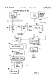
- FIG. 1 is a schematic diagram illustrating the basic components of the ingress/egress management system according to a preferred embodiment of the invention
- FIG. 2 is a block diagram of a typical bi-directional distribution amplifier as used in the cable plant of FIG. 1;
- FIG. 3 is a block diagram showing in more detail the mobile unit used in the ingress/egress management system shown in FIG. 1;
- FIG. 4 is a pictorial representation illustrating the ingress and egress of RF energy at the site of a defect in a coaxial cable
- FIG. 5 is a flow diagram of the software implemented on the headend computer of the ingress/egress management system according to a preferred embodiment of the invention.
- FIG. 6 is map showing the ingress and egress locations as determined by the computer software system of the invention.
- a coaxial cable plant is represented by a coaxial cable 11 having a plurality of downstream bi-directional amplifiers 12 distributed along the length of the cable.
- a hybrid fiber optic and coaxial cable plant is represented by a fiber cable 13 which terminates in a fiber node 14, at which an optical signal is converted to an electrical signal, and a coaxial cable 15 having a plurality of downstream amplifiers 16.
- Both the coaxial cable plant and the hybrid fiber optic and coaxial cable plant emanate from a headend 17 which includes a monitoring receiver 171.
- the output of this receiver is supplied to the computer software system 18.
- cable flaws are indicated by the reference numeral 19. It is the function of the mobile transceiver and GPS system 30 to locate these flaws in a manner which allows the computer software system 18, in response to the output from monitoring receiver 171, to quantify the cable flaws at egress and ingress frequencies and assign a coordinate and figure of merit.
- Cable flaws are frequency dependent, depending on the location of the flaw and its connection to the physical plant, i.e., drop wires, anchors, and other telephone and electric plant in the proximity of the flaw.
- FIG. 2 is a block diagram of a bi-directional amplifier 12 as used in the coaxial cable plant shown in FIG. 1.
- This amplifier has a coaxial input 21 and a coaxial output 22.
- the input and output are connected to respective diplexers 23 and 24 having connected therebetween a down stream amplifier 25, with equalizing and filter circuits, for transmitting signals in the range of 50 MHz to 1 GHz and an up stream amplifier 26, also with equalizing and filter circuits, for transmitting signals in the range of 5 to 50 MHz.
- FIG. 3 shows the mobile transceiver and GPS system 30 in more detail.
- This transceiver comprises a transceiver and GPS system 31 mounted in a vehicle 32, such as a maintenance truck.
- the GPS system includes a receiver connected to a GPS antenna 33.
- the transceiver includes a receiver capable of receiving RF egress from the coaxial cable plant in the 50 MHz to 1 GHz region via the receiving antenna 34. Any such RF egress received is stamped with a GPS coordinate and this information is stored in the transceiver for later downloading and analysis by the computer software system 18.
- the transceiver includes a 5 to 50 MHz transmitter modulated with GPS coordinates. This transmitter transmits via antenna 35 at sufficient power to enter the coaxial cable system flaw and be received a the headend location via the headend receiver 171.
- FIG. 4 illustrates the types of RF leaks detected.
- a flaw 19 is shown between two amplifiers 12.
- the downstream RF energy in the 50 MHz to 1 GHz range will egress from the fault 19 and be detected by the mobile transceiver 31.
- the frequency of the RF energy detected is stored with the GPS coordinates for later analysis.
- the GPS modulated RF energy in the 5 to 50 MHZ range transmitted by the mobile transceiver enters the cable at the flaw 19 and propagates to the headend monitoring receiver 171.
- the headend monitoring receiver thus is always aware of ingress leaks when they are accompanied by sufficient ingress (loss of integrity) from the GPS tagged ingress transmitter signal.
- Cable flaws with sufficient integrity at 5 to 50 MHz but failing in the 50 MHz to 1 GHz region are stored in the mobile transceiver and GPS system 31 for comparison and correlation at the end of the work day by the computer software system 18.
- the headend monitoring receiver 171 when not directly being used in conjunction with a mobile transceiver and GPS system 30, can be tuned in the 5 to 50 MHz band to a strong ingress potential transmitter in the service area to continuously monitor the coaxial plant for ingress.
- a strong ingress potential transmitter is a citizen's band transmitter transmitting at 27 MHz.
- the headend monitoring receiver can be multiplexed to look at multiple legs or multiple headend receivers assigned to unique upstream legs of the coaxial plant to enhance resolution in this mode.
- FIG. 5 is a flow diagram showing the software implemented on the computer software system 18.
- a tunable receiver 51 detects RF signals in the 5 to 50 MHz band and provides an output to the computer software.
- the detected signal is output to decoding function 53 which decodes the signal. Should the signal be lost during the decoding process, a return is made to function block 52 to wait for detection of the signal.
- the decoded information includes signal strength and the GPS coordinates which were stamped on the ingress RF signal and a time stamp. This information is written to a data store in function block 54 as the signal is decoded.
- Stored data from the data store is then read from the data store in operation block 55 as a series of reports. These reports are analyzed in function block 56, and leak summaries are output at 57. This operation is performed under user control in response to selections from a menu 58. In addition to analyzing reports, the user may also select a display of system status function 59, which generates a system status display output 60, and a generate work reports function 61, generates a work reports output 62.
- the leak summaries output 57 include a map, generated from a map database, with the locations of points of ingress and egress. Such a map is shown in FIG. 6. This map provides the technician with a clear indication of where work is to be performed as output in the work reports output 62.
Abstract
Description
Claims (17)
Priority Applications (2)
| Application Number | Priority Date | Filing Date | Title |
|---|---|---|---|
| US08/703,773 US5777662A (en) | 1996-08-27 | 1996-08-27 | Ingress/egress management system |
| CA002241776A CA2241776C (en) | 1996-08-27 | 1998-06-26 | Ingress/egress management system |
Applications Claiming Priority (2)
| Application Number | Priority Date | Filing Date | Title |
|---|---|---|---|
| US08/703,773 US5777662A (en) | 1996-08-27 | 1996-08-27 | Ingress/egress management system |
| CA002241776A CA2241776C (en) | 1996-08-27 | 1998-06-26 | Ingress/egress management system |
Publications (1)
| Publication Number | Publication Date |
|---|---|
| US5777662A true US5777662A (en) | 1998-07-07 |
Family
ID=31979148
Family Applications (1)
| Application Number | Title | Priority Date | Filing Date |
|---|---|---|---|
| US08/703,773 Expired - Lifetime US5777662A (en) | 1996-08-27 | 1996-08-27 | Ingress/egress management system |
Country Status (2)
| Country | Link |
|---|---|
| US (1) | US5777662A (en) |
| CA (1) | CA2241776C (en) |
Cited By (39)
| Publication number | Priority date | Publication date | Assignee | Title |
|---|---|---|---|---|
| US20010010541A1 (en) * | 1998-03-19 | 2001-08-02 | Fernandez Dennis Sunga | Integrated network for monitoring remote objects |
| US6310646B1 (en) * | 1996-11-29 | 2001-10-30 | Wavetek Corporation | Method and apparatus for measuring a radio frequency signal having program information and control information |
| US6313874B1 (en) * | 1997-11-17 | 2001-11-06 | Wavetek Corporation | Method and apparatus for direct detection of communication system leakage signals |
| WO2001089197A2 (en) * | 2000-05-16 | 2001-11-22 | Comsonics, Inc. | Device and method of determining location of signal ingress |
| US20020019983A1 (en) * | 2000-06-05 | 2002-02-14 | Emsley Brett W. | Testing instrument |
| US6359882B1 (en) | 1997-04-01 | 2002-03-19 | Yipes Communications, Inc. | Method and apparatus for transmitting data |
| US20030022645A1 (en) * | 2001-07-26 | 2003-01-30 | Runzo Joseph Donald | System and method for signal validation and leakage detection |
| US6611150B1 (en) | 1999-03-31 | 2003-08-26 | Sadelco, Inc. | Leakage detector for use in combination with a signal level meter |
| US6801162B1 (en) | 2003-04-16 | 2004-10-05 | Cable Leakage Technologies, Inc. | Doppler-based automated direction finding system and method for locating cable television signal leaks |
| US20040210938A1 (en) * | 2003-04-16 | 2004-10-21 | Cable Leakage Technologies, Inc. | Method and system for automatically analyzing and modifying cable television signal leak information |
| US6833859B1 (en) * | 1999-02-01 | 2004-12-21 | Comsonics, Inc. | Method of locating radio frequency leaks in a CATV system |
| US6915530B1 (en) * | 1994-11-30 | 2005-07-05 | General Instrument Corporation | Ingress detection and characterization by time/frequency map |
| US20060067239A1 (en) * | 2004-09-24 | 2006-03-30 | Olinski Jerome E | System and method for fault identification |
| US20060179355A1 (en) * | 2005-02-09 | 2006-08-10 | Magella Bouchard | Autonomous network fault detection and management system |
| US20060248565A1 (en) * | 2005-04-28 | 2006-11-02 | Shimp Richard L | Antenna for cable ingress/egress management signaling |
| US20070022457A1 (en) * | 2005-07-20 | 2007-01-25 | Cable Leakage Technologies, Inc. | Method and system for analyzing cable television signal leak information |
| US7254827B1 (en) * | 2000-05-08 | 2007-08-07 | Sunrise Telecom Incorporated | Ingress monitoring system and method |
| US20080033698A1 (en) * | 2006-08-07 | 2008-02-07 | Trilithic, Inc. | Leakage location methods |
| US20080133308A1 (en) * | 2006-11-27 | 2008-06-05 | Harris James E | Leakage location methods |
| US20080167808A1 (en) * | 2007-01-05 | 2008-07-10 | Harris James E | Method for Displaying Leakage Location and Leakage Magnitude |
| US20090096665A1 (en) * | 2007-10-10 | 2009-04-16 | Acterna Llc | Method For Locating Cable Impairments |
| US20090267615A1 (en) * | 2008-04-25 | 2009-10-29 | Raymond Gregory Jones | System and Method for Sorting Detection of Signal Egress from a Wired Communication System |
| US20090300534A1 (en) * | 2008-05-30 | 2009-12-03 | Trilithic, Inc. | Apparatus and method for displaying network status |
| US20100026310A1 (en) * | 2008-07-31 | 2010-02-04 | Shimp Richard L | Communication System Fault Location Using Signal Ingress Detection |
| US20110043640A1 (en) * | 2009-08-18 | 2011-02-24 | Arcom Digital, Llc | Methods and apparatus for detecting and locating leakage of digital signals |
| US20110085456A1 (en) * | 2009-10-14 | 2011-04-14 | Zimmerman Dennis A | Signal Egress Alarm |
| WO2013019354A1 (en) * | 2011-07-01 | 2013-02-07 | CertusView Technologies, LLC. | Methods and apparatus for ingress mitigation in cable communication systems and increased upstream capacity |
| US8650605B2 (en) | 2012-04-26 | 2014-02-11 | Arcom Digital, Llc | Low-cost leakage detector for a digital HFC network |
| US8752108B2 (en) | 2010-07-21 | 2014-06-10 | Magella Bouchard | System and method for detecting signal ingress interferences |
| US20140195176A1 (en) * | 2013-01-07 | 2014-07-10 | Comsonics, Inc. | Deriving broadband communication system service area for signal leakage detection |
| US8949918B2 (en) | 2013-03-15 | 2015-02-03 | Certusview Technologies, Llc | Hybrid fiber-coaxial (HFC) cable communication systems having well-aligned optical and radio-frequency links to facilitate upstream channel plans having high aggregate data capacity |
| US9021539B2 (en) | 2006-08-07 | 2015-04-28 | Trilithic, Inc. | Leakage location methods |
| US9091712B2 (en) | 2011-10-27 | 2015-07-28 | Comsonics, Inc. | Shielding integrity testing for cable drop |
| US9160407B2 (en) | 2011-06-27 | 2015-10-13 | Trilithic, Inc. | Method for detecting leakage in digitally modulated systems |
| US20160036492A1 (en) * | 2014-07-29 | 2016-02-04 | Cable Television Laboratories, Inc. | Radio frequency leakage detection in a cable plant |
| US9729257B2 (en) | 2014-09-24 | 2017-08-08 | Cable Television Laboratories, Inc. | Isolating an upstream noise source in a cable television network |
| US9882663B2 (en) | 2016-03-17 | 2018-01-30 | Arcom Digital, Llc | Doppler location of signal leaks in an HFC network |
| US20210285841A1 (en) * | 2020-03-14 | 2021-09-16 | Effigis Géo-Solutions Inc. | Using ingress for leakage determination in cable networks |
| US20230049697A1 (en) * | 2021-08-10 | 2023-02-16 | Charter Communications Operating, Llc | System and method for detecting cable system signal ingress |
Citations (6)
| Publication number | Priority date | Publication date | Assignee | Title |
|---|---|---|---|---|
| US4072899A (en) * | 1976-04-26 | 1978-02-07 | Comsonics, Inc. | RF leak detector |
| US4413229A (en) * | 1981-06-02 | 1983-11-01 | Grant William O | Method and apparatus for remote indication of faults in coaxial cable R-F transmission systems |
| US5294937A (en) * | 1992-05-20 | 1994-03-15 | Cable Leakage Technologies | Cable leakage monitoring system |
| US5465112A (en) * | 1992-12-02 | 1995-11-07 | Fujitsu Limited | Testing apparatus for detecting an image signal in radio waves leaking from an information processing system |
| US5585842A (en) * | 1994-09-19 | 1996-12-17 | Wavetek Corporation | CATV frequency sweep testing using RF transmitter to generate test signals |
| US5608428A (en) * | 1994-06-09 | 1997-03-04 | Trilithic, Inc. | Radio frequency leakage detection system for CATV system |
-
1996
- 1996-08-27 US US08/703,773 patent/US5777662A/en not_active Expired - Lifetime
-
1998
- 1998-06-26 CA CA002241776A patent/CA2241776C/en not_active Expired - Fee Related
Patent Citations (6)
| Publication number | Priority date | Publication date | Assignee | Title |
|---|---|---|---|---|
| US4072899A (en) * | 1976-04-26 | 1978-02-07 | Comsonics, Inc. | RF leak detector |
| US4413229A (en) * | 1981-06-02 | 1983-11-01 | Grant William O | Method and apparatus for remote indication of faults in coaxial cable R-F transmission systems |
| US5294937A (en) * | 1992-05-20 | 1994-03-15 | Cable Leakage Technologies | Cable leakage monitoring system |
| US5465112A (en) * | 1992-12-02 | 1995-11-07 | Fujitsu Limited | Testing apparatus for detecting an image signal in radio waves leaking from an information processing system |
| US5608428A (en) * | 1994-06-09 | 1997-03-04 | Trilithic, Inc. | Radio frequency leakage detection system for CATV system |
| US5585842A (en) * | 1994-09-19 | 1996-12-17 | Wavetek Corporation | CATV frequency sweep testing using RF transmitter to generate test signals |
Cited By (87)
| Publication number | Priority date | Publication date | Assignee | Title |
|---|---|---|---|---|
| US6915530B1 (en) * | 1994-11-30 | 2005-07-05 | General Instrument Corporation | Ingress detection and characterization by time/frequency map |
| US6310646B1 (en) * | 1996-11-29 | 2001-10-30 | Wavetek Corporation | Method and apparatus for measuring a radio frequency signal having program information and control information |
| US6359882B1 (en) | 1997-04-01 | 2002-03-19 | Yipes Communications, Inc. | Method and apparatus for transmitting data |
| US6313874B1 (en) * | 1997-11-17 | 2001-11-06 | Wavetek Corporation | Method and apparatus for direct detection of communication system leakage signals |
| US7830962B1 (en) | 1998-03-19 | 2010-11-09 | Fernandez Dennis S | Monitoring remote patients |
| US20090160939A1 (en) * | 1998-03-19 | 2009-06-25 | Lot 3 Acquisition Foundation, Llc | Mobile unit communication via a network |
| US20010029613A1 (en) * | 1998-03-19 | 2001-10-11 | Fernandez Dennis Sunga | Integrated network for monitoring remote objects |
| US7920626B2 (en) | 1998-03-19 | 2011-04-05 | Lot 3 Acquisition Foundation, Llc | Video surveillance visual recognition |
| US20010010541A1 (en) * | 1998-03-19 | 2001-08-02 | Fernandez Dennis Sunga | Integrated network for monitoring remote objects |
| US7839432B2 (en) | 1998-03-19 | 2010-11-23 | Dennis Sunga Fernandez | Detector selection for monitoring objects |
| US9609283B2 (en) | 1998-03-19 | 2017-03-28 | Cufer Asset Ltd. L.L.C | Mobile unit communication via a network |
| US8493442B2 (en) * | 1998-03-19 | 2013-07-23 | Lot 3 Acquisition Foundation, Llc | Object location information |
| US20010022615A1 (en) * | 1998-03-19 | 2001-09-20 | Fernandez Dennis Sunga | Integrated network for monitoring remote objects |
| US8335254B1 (en) | 1998-03-19 | 2012-12-18 | Lot 3 Acquisition Foundation, Llc | Advertisements over a network |
| US6833859B1 (en) * | 1999-02-01 | 2004-12-21 | Comsonics, Inc. | Method of locating radio frequency leaks in a CATV system |
| US6611150B1 (en) | 1999-03-31 | 2003-08-26 | Sadelco, Inc. | Leakage detector for use in combination with a signal level meter |
| US7254827B1 (en) * | 2000-05-08 | 2007-08-07 | Sunrise Telecom Incorporated | Ingress monitoring system and method |
| WO2001089197A2 (en) * | 2000-05-16 | 2001-11-22 | Comsonics, Inc. | Device and method of determining location of signal ingress |
| US6978476B2 (en) * | 2000-05-16 | 2005-12-20 | Comsonics | Device and method of determining location of signal ingress |
| US20030033609A1 (en) * | 2000-05-16 | 2003-02-13 | Zimmerman Dennis A | Device and method of determining location of signal ingress |
| WO2001089197A3 (en) * | 2000-05-16 | 2002-03-28 | Comsonics Inc | Device and method of determining location of signal ingress |
| US20020019983A1 (en) * | 2000-06-05 | 2002-02-14 | Emsley Brett W. | Testing instrument |
| US20030022645A1 (en) * | 2001-07-26 | 2003-01-30 | Runzo Joseph Donald | System and method for signal validation and leakage detection |
| US7395548B2 (en) | 2001-07-26 | 2008-07-01 | Comsonics, Inc. | System and method for signal validation and leakage detection |
| US20040210938A1 (en) * | 2003-04-16 | 2004-10-21 | Cable Leakage Technologies, Inc. | Method and system for automatically analyzing and modifying cable television signal leak information |
| US6801162B1 (en) | 2003-04-16 | 2004-10-05 | Cable Leakage Technologies, Inc. | Doppler-based automated direction finding system and method for locating cable television signal leaks |
| US7548201B2 (en) | 2003-04-16 | 2009-06-16 | Cable Leakage Technologies, Inc. | Method and system for automatically analyzing and modifying cable television signal leak information |
| US7558212B2 (en) * | 2004-09-24 | 2009-07-07 | Bce Inc. | System and method for fault identification |
| US20060067239A1 (en) * | 2004-09-24 | 2006-03-30 | Olinski Jerome E | System and method for fault identification |
| US20060179355A1 (en) * | 2005-02-09 | 2006-08-10 | Magella Bouchard | Autonomous network fault detection and management system |
| US7360124B2 (en) | 2005-02-09 | 2008-04-15 | Viasat Geo-Technologie Inc. | Autonomous network fault detection and management system |
| US20060248565A1 (en) * | 2005-04-28 | 2006-11-02 | Shimp Richard L | Antenna for cable ingress/egress management signaling |
| US20070022457A1 (en) * | 2005-07-20 | 2007-01-25 | Cable Leakage Technologies, Inc. | Method and system for analyzing cable television signal leak information |
| US20110145873A1 (en) * | 2005-07-20 | 2011-06-16 | Cable Leakage Technologies, Inc. | Method and System for Analyzing Cable Television Signal Leak Information |
| US7945939B2 (en) | 2005-07-20 | 2011-05-17 | Cable Leakage Technologies, Inc. | Method and system for analyzing cable television signal leak information |
| US20080033698A1 (en) * | 2006-08-07 | 2008-02-07 | Trilithic, Inc. | Leakage location methods |
| US9021539B2 (en) | 2006-08-07 | 2015-04-28 | Trilithic, Inc. | Leakage location methods |
| US20080133308A1 (en) * | 2006-11-27 | 2008-06-05 | Harris James E | Leakage location methods |
| US20080167808A1 (en) * | 2007-01-05 | 2008-07-10 | Harris James E | Method for Displaying Leakage Location and Leakage Magnitude |
| US20090096665A1 (en) * | 2007-10-10 | 2009-04-16 | Acterna Llc | Method For Locating Cable Impairments |
| US8154303B2 (en) * | 2007-10-10 | 2012-04-10 | Ben Maxson | Method for locating cable impairments |
| US7952363B2 (en) * | 2008-04-25 | 2011-05-31 | Comsonics, Inc. | System and method for sorting detection of signal egress from a wired communication system |
| US20090267615A1 (en) * | 2008-04-25 | 2009-10-29 | Raymond Gregory Jones | System and Method for Sorting Detection of Signal Egress from a Wired Communication System |
| US20090300534A1 (en) * | 2008-05-30 | 2009-12-03 | Trilithic, Inc. | Apparatus and method for displaying network status |
| US20100026310A1 (en) * | 2008-07-31 | 2010-02-04 | Shimp Richard L | Communication System Fault Location Using Signal Ingress Detection |
| US8143900B2 (en) * | 2008-07-31 | 2012-03-27 | Comsonics, Inc. | Communication system fault location using signal ingress detection |
| US9038119B2 (en) | 2009-08-18 | 2015-05-19 | Arcom Digital, Llc | Low-cost leakage detector for a digital HFC network |
| US8904460B2 (en) | 2009-08-18 | 2014-12-02 | Arcom Digital, Llc | Methods and apparatus for locating leakage of digital signals |
| US9709621B2 (en) | 2009-08-18 | 2017-07-18 | Arcom Digital, Llc | Leakage detection of digital signals in an HFC network |
| WO2011022197A1 (en) | 2009-08-18 | 2011-02-24 | Arcom Digital, Llc | Method and apparatus for detecting and locating leakage of digital signals |
| US8456530B2 (en) | 2009-08-18 | 2013-06-04 | Arcom Digital, Llc | Methods and apparatus for detecting and locating leakage of digital signals |
| US20110043640A1 (en) * | 2009-08-18 | 2011-02-24 | Arcom Digital, Llc | Methods and apparatus for detecting and locating leakage of digital signals |
| US20110085456A1 (en) * | 2009-10-14 | 2011-04-14 | Zimmerman Dennis A | Signal Egress Alarm |
| US8752108B2 (en) | 2010-07-21 | 2014-06-10 | Magella Bouchard | System and method for detecting signal ingress interferences |
| US10334291B2 (en) | 2011-06-27 | 2019-06-25 | Viavi Solutions, Inc. | Apparatus for detecting leakage in digitally modulated systems |
| US9877050B2 (en) | 2011-06-27 | 2018-01-23 | Trilithic, Inc. | Apparatus for detecting leakage in digitally modulated systems |
| US9160407B2 (en) | 2011-06-27 | 2015-10-13 | Trilithic, Inc. | Method for detecting leakage in digitally modulated systems |
| US8650606B2 (en) | 2011-07-01 | 2014-02-11 | Certusview Technologies, Llc | Cable communication systems and methods employing 256-QAM upstream channels and having increased upstream capacity for supporting voice and/or data services |
| US20160173195A1 (en) * | 2011-07-01 | 2016-06-16 | Certusview Technologies, Llc | Methods for ingress remediation in cable communication systems |
| WO2013019354A1 (en) * | 2011-07-01 | 2013-02-07 | CertusView Technologies, LLC. | Methods and apparatus for ingress mitigation in cable communication systems and increased upstream capacity |
| US8948596B2 (en) | 2011-07-01 | 2015-02-03 | CetusView Technologies, LLC | Neighborhood node mapping methods and apparatus for ingress mitigation in cable communication systems |
| US8977132B2 (en) | 2011-07-01 | 2015-03-10 | Certusview Technologies, Llc | Ingress-mitigated RF cable plants and ingress mitigation methods for same |
| US9019855B2 (en) | 2011-07-01 | 2015-04-28 | Certusview Technologies, Llc | Cable communication systems and methods employing TDMA/ATDMA QAM upstream channels below 20 MHz for increased upstream capacity to support voice and/or data services |
| US8806559B2 (en) | 2011-07-01 | 2014-08-12 | Certusview Technologies, Llc | Methods for ingress mitigation in cable communication systems involving repair, replacement and/or adjustment of infrastructure elements |
| US10084538B2 (en) | 2011-07-01 | 2018-09-25 | Certusview Technologies, Llc | Cable communication systems and methods employing 256-QAM upstream channels and having increased upstream capacity for supporting voice and/or data services |
| US9088310B2 (en) | 2011-07-01 | 2015-07-21 | Certusview Technologies, Llc | Cable communication systems and methods employing QAM upstream channels below 16.4 MHz for increased aggregate deployed upstream capacity |
| US8532488B2 (en) | 2011-07-01 | 2013-09-10 | Certusview Technologies, Llc | Cable communication systems and methods employing QAM upstream channels below 16.4 MHz for increased aggregate deployed upstream capacity to support voice and/or data services |
| US8543003B2 (en) | 2011-07-01 | 2013-09-24 | Certusview Technologies, Llc | Ingress-mitigated cable communication systems and methods having increased upstream capacity for supporting voice and/or data services |
| US8578437B2 (en) | 2011-07-01 | 2013-11-05 | Certusview Technologies, Llc | Methods for ingress mitigation in cable communication systems involving repair, replacement and/or adjustment of infrastructure elements |
| GB2493815B (en) * | 2011-07-01 | 2015-11-11 | Certusview Technologies Llc | Methods and apparatus for ingress mitigation in cable communication systems, and cable communication systems and methods having increased upstream capacity |
| GB2507382B (en) * | 2011-07-01 | 2016-02-10 | Certusview Technologies Llc | Methods and apparatus for ingress mitigation in cable communication systems, and cable communication systems and methods having increased upstream capacity |
| AU2012290678B2 (en) * | 2011-07-01 | 2016-02-25 | CertusView Technologies, LLC. | Methods and apparatus for ingress mitigation in cable communication systems and increased upstream capacity |
| US8811191B2 (en) | 2011-07-01 | 2014-08-19 | Certusview Technologies, Llc | Iterative mapping methods for ingress mitigation in cable communication systems |
| US9577746B2 (en) * | 2011-07-01 | 2017-02-21 | Certusview Technologies, Llc | Methods for ingress remediation in cable communication systems |
| US9091712B2 (en) | 2011-10-27 | 2015-07-28 | Comsonics, Inc. | Shielding integrity testing for cable drop |
| US8650605B2 (en) | 2012-04-26 | 2014-02-11 | Arcom Digital, Llc | Low-cost leakage detector for a digital HFC network |
| US20140195176A1 (en) * | 2013-01-07 | 2014-07-10 | Comsonics, Inc. | Deriving broadband communication system service area for signal leakage detection |
| US9641263B2 (en) * | 2013-01-07 | 2017-05-02 | Comsonics, Inc. | Deriving broadband communication system service area for signal leakage detection |
| US9660729B2 (en) | 2013-03-15 | 2017-05-23 | Certusview Technologies, Llc | Cable communication system optical nodes having selectable attenuation values to mitigate distortion of upstream information |
| US8949918B2 (en) | 2013-03-15 | 2015-02-03 | Certusview Technologies, Llc | Hybrid fiber-coaxial (HFC) cable communication systems having well-aligned optical and radio-frequency links to facilitate upstream channel plans having high aggregate data capacity |
| US9455766B2 (en) * | 2014-07-29 | 2016-09-27 | Cable Television Laboratories, Inc | Radio frequency leakage detection in a cable plant |
| US20160036492A1 (en) * | 2014-07-29 | 2016-02-04 | Cable Television Laboratories, Inc. | Radio frequency leakage detection in a cable plant |
| US9729257B2 (en) | 2014-09-24 | 2017-08-08 | Cable Television Laboratories, Inc. | Isolating an upstream noise source in a cable television network |
| US9882663B2 (en) | 2016-03-17 | 2018-01-30 | Arcom Digital, Llc | Doppler location of signal leaks in an HFC network |
| US20210285841A1 (en) * | 2020-03-14 | 2021-09-16 | Effigis Géo-Solutions Inc. | Using ingress for leakage determination in cable networks |
| US20230049697A1 (en) * | 2021-08-10 | 2023-02-16 | Charter Communications Operating, Llc | System and method for detecting cable system signal ingress |
| US11846666B2 (en) * | 2021-08-10 | 2023-12-19 | Charter Communications Operating Llc | System and method for detecting cable system signal ingress |
Also Published As
| Publication number | Publication date |
|---|---|
| CA2241776C (en) | 1999-09-07 |
Similar Documents
| Publication | Publication Date | Title |
|---|---|---|
| US5777662A (en) | Ingress/egress management system | |
| US7111318B2 (en) | Communication system work order performance method and system | |
| US11856182B2 (en) | Icon-based home certification, in-home leakage testing, and antenna matching pad | |
| US7395548B2 (en) | System and method for signal validation and leakage detection | |
| US20140267788A1 (en) | Method for identifying and prioritizing fault location in a cable plant | |
| US20120257661A1 (en) | Shielding flaw detection and measurement in quadrature amplitude modulated cable telecommunications environment | |
| JP2007522709A (en) | Antenna system telemetry monitoring apparatus and method using mobile communication terminal | |
| US7580708B1 (en) | Comprehensive network monitoring at broadcast satellite sites located outside of the broadcast service area | |
| US20210285841A1 (en) | Using ingress for leakage determination in cable networks | |
| US20140270095A1 (en) | Method for identifying fault location in network trunk | |
| US10284258B2 (en) | Method and system for interference detection and diagnostic in cable networks | |
| US7034545B2 (en) | Apparatus and method for monitoring transmission systems using off-frequency signals | |
| US11650266B2 (en) | Systems and methods for detecting leakage in a cable network system | |
| WO2000013424A1 (en) | Catv return path impairment detection and location system | |
| EP1082617A1 (en) | Method for detecting the position of defective shielding of a coaxial cable or connector in a coaxial cable network | |
| US10848714B1 (en) | Systems and methods for detecting leakage using inertial devices | |
| JP2006067000A (en) | Reception area monitor system, broadcast receiver and operation management apparatus of the reception area monitor system, and reception area monitor method | |
| Wider et al. | Operational Practice for Identifying, Locating and Mitigating UHF Ingress and Direct Pickup in Cable Networks and Devices | |
| Series | Stealth Digital Analyzer Operation Manual | |
| Headquarters | Ordering information | |
| Bowie | Systems approach to determination of television coverage | |
| Powers | Broad-band systems standards | |
| Lowver | Monitoring and Control for Digital Transmission Systems | |
| JP2001111979A (en) | Data transmitting system |
Legal Events
| Date | Code | Title | Description |
|---|---|---|---|
| AS | Assignment |
Owner name: COMSONICS, INC., VIRGINIA Free format text: ASSIGNMENT OF ASSIGNORS INTEREST;ASSIGNOR:ZIMMERMAN, DENNIS A.;REEL/FRAME:008207/0861 Effective date: 19960826 |
|
| STCF | Information on status: patent grant |
Free format text: PATENTED CASE |
|
| RF | Reissue application filed |
Effective date: 20000623 |
|
| FPAY | Fee payment |
Year of fee payment: 4 |
|
| FEPP | Fee payment procedure |
Free format text: PAYOR NUMBER ASSIGNED (ORIGINAL EVENT CODE: ASPN); ENTITY STATUS OF PATENT OWNER: SMALL ENTITY |
|
| FPAY | Fee payment |
Year of fee payment: 8 |
|
| FPAY | Fee payment |
Year of fee payment: 12 |
|
| AS | Assignment |
Owner name: PNC BANK, NATIONAL ASSOCIATION, VIRGINIA Free format text: SECURITY INTEREST;ASSIGNOR:COMSONICS, INC.;REEL/FRAME:036166/0346 Effective date: 20150630 |
|
| AS | Assignment |
Owner name: COMSONICS, INC., VIRGINIA Free format text: RELEASE BY SECURED PARTY;ASSIGNOR:PNC BANK, NATIONAL ASSOCIATION;REEL/FRAME:052283/0538 Effective date: 20200330 |