US4460120A - Narrow bodied, single- and twin-windowed portable laser scanning head for reading bar code symbols - Google Patents
Narrow bodied, single- and twin-windowed portable laser scanning head for reading bar code symbols Download PDFInfo
- Publication number
- US4460120A US4460120A US06/519,107 US51910783A US4460120A US 4460120 A US4460120 A US 4460120A US 51910783 A US51910783 A US 51910783A US 4460120 A US4460120 A US 4460120A
- Authority
- US
- United States
- Prior art keywords
- head
- scanning
- bar code
- laser
- symbol
- Prior art date
- Legal status (The legal status is an assumption and is not a legal conclusion. Google has not performed a legal analysis and makes no representation as to the accuracy of the status listed.)
- Expired - Lifetime
Links
Images


Classifications
-
- G—PHYSICS
- G06—COMPUTING; CALCULATING OR COUNTING
- G06K—GRAPHICAL DATA READING; PRESENTATION OF DATA; RECORD CARRIERS; HANDLING RECORD CARRIERS
- G06K7/00—Methods or arrangements for sensing record carriers, e.g. for reading patterns
- G06K7/10—Methods or arrangements for sensing record carriers, e.g. for reading patterns by electromagnetic radiation, e.g. optical sensing; by corpuscular radiation
- G06K7/10544—Methods or arrangements for sensing record carriers, e.g. for reading patterns by electromagnetic radiation, e.g. optical sensing; by corpuscular radiation by scanning of the records by radiation in the optical part of the electromagnetic spectrum
- G06K7/10821—Methods or arrangements for sensing record carriers, e.g. for reading patterns by electromagnetic radiation, e.g. optical sensing; by corpuscular radiation by scanning of the records by radiation in the optical part of the electromagnetic spectrum further details of bar or optical code scanning devices
- G06K7/10881—Methods or arrangements for sensing record carriers, e.g. for reading patterns by electromagnetic radiation, e.g. optical sensing; by corpuscular radiation by scanning of the records by radiation in the optical part of the electromagnetic spectrum further details of bar or optical code scanning devices constructional details of hand-held scanners
-
- G—PHYSICS
- G06—COMPUTING; CALCULATING OR COUNTING
- G06K—GRAPHICAL DATA READING; PRESENTATION OF DATA; RECORD CARRIERS; HANDLING RECORD CARRIERS
- G06K17/00—Methods or arrangements for effecting co-operative working between equipments covered by two or more of main groups G06K1/00 - G06K15/00, e.g. automatic card files incorporating conveying and reading operations
- G06K17/0022—Methods or arrangements for effecting co-operative working between equipments covered by two or more of main groups G06K1/00 - G06K15/00, e.g. automatic card files incorporating conveying and reading operations arrangements or provisious for transferring data to distant stations, e.g. from a sensing device
Definitions
- the present invention generally relates to laser scanning systems for scanning, reading and/or analyzing bar code symbols and, more particularly, to a light-weight, easy-to-manipulate, non-arm-and wrist-fatiguing, hand-held, narrow-bodied, single- and twin-windowed, laser scanning head supportable entirely by a user throughout the reading of the symbols. Still more particularly, this invention relates to a field-replaceable laser tube arrangement to permit rapid and easy tube replacement; to a novel laser tube and method of making the same; to an arrangement for, and method of, controlling a scanning system; to optical passive elements for increasing the depth of field; to a trigger protective device; and to a one-piece machinable or moldable plastic support bench and method of making the same.
- true laser scanners such as point-of-sale or deck scanners of the moving-beam or fixed-beam type, have been built into stationary counters.
- these deck scanners are large, massive, stationary installations.
- symbol-bearing objects are too heavy, or too big, or too inconvenient to be brought to the stationary scanning installation. Some objects may be stationary themselves.
- semi-portable laser scanning heads such as disclosed in U.S. Pat. No. 4,251,798 were designed to permit the user to bring the scanning head to the object.
- semi-portable heads weighed over three pounds, had to be partially supported by the object itself, and were too heavy and somewhat difficult to readily manipulate, particularly for those assembly-line applications where a user was routinely required to repetitively manipulate the semi-portable head many times per minute, every hour and on a daily basis.
- the wide-bodied head had a gun-shaped configuration. It was desirable in some applications to insert the gun-shaped head, when not in use, into a user-supported holster of the kind traditionally used to receive and support firearms.
- the wide snout on the wide-bodied head did not lend itself to conveniently fit in the traditional gun holster. Hence, the wide-heads were typically tossed and left on the nearest table, and were prone to being damaged, misplaced and lost.
- the optical system of a laser scanner head generally used a negative lens at the output end of the laser tube to diverge the collimated laser beam, and thereupon, used a positive lens to focus the diverging laser beam to a spot of predetermined diameter at a reference plane located exteriorly of the head.
- the negative lens represented a component of given weight, size and cost, and in the context of a laser scanner head to be made as light-weight, miniature and inexpensive as possible, a component which it was desirable to eliminate.
- Another object of this invention is to reduce the rather large case width heretofore required in prior art wide-bodied laser scanning heads.
- Still another object of this invention is to eliminate the amount of dead space within the head.
- Yet another object of this invention is to provide a laser scanning head which is so light-in-weight and small-in-volume, that it can be easily held in a user's hand without causing arm- and wrist-fatigue, while being easy-to-manipulate, even for those assembly-line applications where the user is routinely required to repetitively manipulate the head many times per minute, every hour, and on a daily basis.
- An additional object of this invention is to provide a fully portable laser scanning head weighing on the order of one pound.
- a further object of this invention is to eliminate the wide snout heretofore present on prior art wide-bodied laser scanning heads.
- Still another object of this invention is to provide a narrow-bodied laser scanning head which can readily be received and supported in a traditional V-shaped gun holster, thereby preventing possible damage to, and misplacement and loss of, the head.
- Yet another object of this invention is to prevent dirt specks on the laser exit window of the laser scanning head from adversely affecting the reading of the bar code symbol.
- Another object of this invention is to automatically optically align the laser tube with the optic system during tube replacement without requiring skilled technicians or specialized equipment to effect the replacement.
- Still another object of the invention is to replace the user laser tube in the head without requiring any desoldering or soldering of any electrical power wires.
- Yet another object of this invention is to eliminate the negative lens of the optical system, and thereby reduce the overall weight, size and cost of the head.
- a further object of this invention is to make the field of view of the incident laser beam traveling towards the symbol and/or the reflected laser beam traveling back from the symbol substantially independent of the case width of the head.
- Another additional object of this invention is to make the field of view of the incident laser beam and/or the reflected laser beam larger then the case width of the head.
- a further object of this invention is to provide a laser sanning head which is shock-resistant and resists twisting of the head.
- Yet a further object of this invention is to minimize battery power drain by actuating all of the actuatable components in the laser scanning head only when they are operative to read and process the symbol, and by deactuating all of the actuatable components in the head after the symbol reading and processing has been concluded.
- Still a further object of this invention is to independently actuate and deactuate all of the actuatable components in the laser scanning head by independently operable means on the head and remote therefrom.
- Another object of this invention is to eliminate the electrical power and communications cable between the laser scanning head and the remainder of the scanning system.
- Still another object of this invention is to provide a twin-windowed laser scanning head combining the advantages of optimum field of view for the incident laser beam, optimum field of view for the reflected laser beam, low spot speed scanning variation for the laser beam, low sensitivity to dirt specks on the laser beam exit or scanning window, highlight sensor effectiveness, ease of judging scanning distance to the light sensor, and minimum case width.
- a scanning head of a scanning system for reading bar code symbols The head is preferably of light-weight, narrow-bodied, easy-to-manipulate, non-arm-and-wrist fatiguing, and is hand-held and supportable entirely by a user during symbol reading.
- the head has an elongated body portion and includes a front region, a rear region, and an intermediate body region extending between the front and rear regions.
- the head has a predetermined width defined by a pair of opposing side walls spaced transversely apart of each other.
- the hand-held head has a gun-shaped housing, and has a handle portion mounted below the body portion.
- the head includes a light source means, e.g. a miniature laser tube or a semiconductor laser diode, mounted within the head, for generating an incident light beam.
- Optic means e.g. an optical train consisting of at least one lens and light-reflecting mirrors, is also mounted within the head, and is operative for directing the incident beam along a light path towards a reference plane located exteriorly of the housing in the vicinity of the front thereof, and also towards a bar code symbol located in the vicinity of the reference plane.
- a reflected light beam is reflected off the symbol, and is directed along a light path away from the reference plane and back towards the housing.
- the head further includes scanning means, e.g. a miniature high-speed scanning motor or a miniature mirrored polygon, mounted within the head at the rear region thereof, for sweeping at least one of the beams, i.e. either the incident beam, or the reflected beam, or both, over a field of view across the bar code symbol.
- Sensor means e.g. a pair of miniature photodiodes, is also mounted within the head, for detecting the light intensity in the reflected beam over a field of view across the bar code symbol, and for generating an electrical analog signal indicative of the detected light intensity.
- Signal processing means e.g. analog-to-digital processing circuitry, is also mounted within the head, for processing the analog signal into a digitized signal to generate therefrom data descriptive of the bar code symbol.
- window means is mounted on the housing, and in a broad aspect of this invention, a single light-transmissive window is mounted at the rear region of the head in close adjacent confronting relationship with the scanning means thereat.
- the window is configured and positioned in the light path of the swept beam, i.e. either the incident beam, or the reflected beam, or both, to permit the swept beam to pass through the window and unobstructedly travel exteriorly of and past the front and intermediate body regions of the housing.
- the field of view of the swept beam is substantially independent of the width of the housing.
- the angular distance through which the incident and/or reflected beams are swept is no longer a function of the width of the housing.
- the incident and/or reflected beams can now be swept over an angular distance which is greater than the housing width.
- the angular distance through which the incident and/or reflected beams are swept can be maintained at the industrial standard, and the width of the housing can be made much narrower in comparison to prior art wide-bodied designs.
- the amount of dead space within the head has been significantly reduced.
- the overall size and weight of the head is likewise much reduced, thereby further contributing to the full portability and ease of manipulation features of this invention.
- the designer of miniaturized laser scanning heads is no longer restricted to wide-bodied head configurations.
- the wide snout at the front of the prior art heads is no longer a design restraint.
- the narrow-bodied and streamlined design of the head of this invention can readily be received and supported in a traditional V-shaped gun holster, thereby preventing possible damage to, and misplacement and loss of, the head.
- the window at the rear region of the head adjacent the scanning means constitutes a scan window through which the incident beam passes en route to the bar code symbol.
- Another light-transmissive non-scan window is mounted at the front region of the head in close adjacent confronting relationship with the sensor means also located thereat.
- the non-scan window is configured and positioned in the light path of the reflected beam to permit the latter to pass therethrough to the sensor means.
- the closeness of the scan window relative to the scanning means maximizes the field of view of the incident beam; and the closeness of the non-scan window relative to the sensor means maximizes the field of view of the reflected beam, and increases the light sensor signal .
- the scan window is advantageously located further from the reference plane and the front region of the housing as compared to the location of the non-scan window. This rearward mounting of the scan window helps to minimize the effect of dirt specks on the scan window.
- a reversal of parts causes the rear scan window to be positioned in the light path of the reflected beam, whereas the front non-scan window is positioned in the light path of the incident beam.
- the light source is mounted at the front of the head in close adjacent confronting relationship with the non-scan window located thereat.
- the scanning means remains at the rear of the head adjacent the scan window. In operation, the light source illuminates the symbol, and the reflected beam travels unobstructedly and exteriorly of and past the front and intermediate body regions of the head.
- the scanning means sweeps the reflected beam and, in turn, directs the swept beam to the sensor means for further processing.
- only a single window is mounted at the rear of the head in close adjacent confronting relationship with the scanning means thereat.
- the single window is configured and positioned in the light paths of both the swept incident and reflected beams to permit both beams to pass through the window and unobstructedly travel exteriorly of and past the front and intermediate body regions of the head.
- Yet another feature of this invention resides in a field-replaceable laser tube arrangement which automatically optically aligns the laser tube with the optic system of the head during tube replacement without requiring skilled technicians or specialized equipment to effect the replacement, and without requiring and desoldering or soldering of any electrical power wires.
- An additional feature of this invention resides in eliminating the negative lens of the optical system by modifying the laser tube of the head to have a diverging output laser beam.
- the output beam of the laser tube was collimated, i.e. had a substantially flat wavefront. It was necessary therefore to use a negative lens to diverge the collimated laser beam, and thereupon, to use a positive lens to focus the diverging laser beam to a circular spot of predetermined diameter at the reference plane.
- the negative lens and its attendant weight, size, space requirements and cost aspects are eliminated, thereby contributing to the overall portability of the head.
- Still other features relate to increasing the depth of field by using optical passive elements rather than electronic circuitry, minimizing battery drain by actuating the components in the head only when the symbol is being read, and fabricating an optical support bench by mass-production techniques.
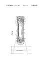
- FIG. 1 is a side sectional view of a gun-shaped, narrow-bodied, twin-windowed embodiment of a laser tube-based portable laser scanning head in accordance with this invention
- FIG. 2 is a partially broken-away, top sectional view of the embodiment of FIG. 1;
- FIG. 3 is a rear sectional view as taken along line 3--3 of FIG. 1;
- FIG. 4 is a top plan sectional view of a detail of the embodiment of FIG. 1, showing the laser tube and part of the optical train;
- FIG. 5 is a front elevational view of the embodiment of FIG. 1;
- FIG. 6 is a front perspective view of the FIG. 1 embodiment, on a much smaller scale, and diagramatically shows the interconnection of the head to the remainder of the scanning system;
- FIG. 7A is a top plan schematic view of a prior art wide-bodied head
- FIG. 7B is a top plan schematic view of an alternate, but unacceptable, design of a laser scanning head
- FIG. 7C is a top plan schematic view of another alternate, but unacceptable, design of a laser scanning head
- FIG. 7D is a top plan schematic view of the laser scanning head of FIG. 1;
- FIG. 8 is a side sectional view of a gun-shaped, narrow-bodied, twin-windowed embodiment of a laser diode-based portable laser scanning head in accordance with this invention.
- FIG. 9 is a partially sectioned, top plan view of the embodiment of FIG. 8;
- FIG. 10 is a side schematic view of a gun-shaped, narrow-bodied, twin-windowed embodiment of a light-based portable scanning head in accordance with this invention.
- FIG. 11 is a top plan schematic view of the embodiment of FIG. 10;
- FIG. 12 is a side schematic view of a gun-shaped, narrow-bodied, single-windowed, retro-reflective embodiment of a light-based scanning head in accordance with this invention.
- FIG. 13 is a top plan schematic view of the embodiment of FIG. 12;
- FIG. 14 is a partially schematic rear elevational view of the components mounted in the rear region of the FIG. 12 embodiment
- FIG. 15 is a field-replaceable laser tube arrangement for use in any of the aforementioned laser tube-based embodiments
- FIG. 16 is a partially schematic, partially sectional, side view of a novel laser tube having a diverging output laser beam made in accordance with one method of this invention.
- FIG. 17 is a partially schematic, partially sectional, side view of a novel laser tube having a diverging output laser beam made in accordance with another method of this invention.
- reference numeral 10 generally identifies a light-weight, narrow-bodied, streamlined, narrow-snouted, hand-held, fully portable, easy-to-manipulate, non-arm-and-wrist-fatiguing, twin-windowed laser scanning head supportable entirely by a user for use in a laser scanning system operative for reading, scanning and/or analyzing bar code symbols throughout the reading thereof.
- Such symbols comprise a series of lines and spaces of varying widths, which pattern decodes to a multiple-digit representation characteristic of the product bearing the symbol.
- Typical symbol bar codes in current use are the Universal Product Code (UPC), EAN, Codabar and Code 39.
- the head 10 includes a generally gun-shaped housing having a handle portion 12 and an elongated narrow-bodied barrel or body portion 14.
- the handle portion 12 has a cross-sectional dimension and overall size such that it can conveniently fit in the palm of a user's hand.
- Both the body and handle portions are constituted of a light-weight, resilient, shock-resistant, self-supporting material, such as a synthetic plastic material.
- the plastic housing is preferably injectionmolded, but can be vacuum-formed or blow-molded to form a thin shell which is hollow and bounds an interior space whose volume measures less than a value which is on the order of 50 cubic inches.
- the specific value of 50 cubic inches is not intended to be self-limiting, but has been provided merely to give an approximation of the overall maximum volume and size of the head 10.
- the overall volume can be less than 50 cubic inches and, indeed, in some applications, the volume is on the order of 25 cubic inches.
- the body portion 14 is generally horizontally elongated along a longitudinal axis, and has a front region 16 at the front end, a raised rear region 18 at the rear end, and an intermediate body region 20 extending between the front and rear regions.
- the body portion 14 has a top wall 11 above which the raised rear region 18 projects, a bottom wall 13 below the top wall, a pair of opposed side walls 15, 17 spaced transversely apart of each other by a predetermined width dimension, a front or nose 19, and a rear wall 21 spaced rearwardly of the front wall.
- a light source means i.e., laser tube 22 having an anode or output end 23 (see FIG. 4) and a cathode or non-output end 25, is mounted within the body portion 14 lengthwise along the longitudinal axis, and is operative for generating an incident collimated laser beam.
- An optic means i.e., an optic train, is likewise mounted within the body portion, and is operative for directing the incident beam along a light path towards a reference plane located exteriorly of the housing in the vicinity of the front region 16, as shown in FIGS. 1 and 2.
- a bar code symbol to be read is located in the vicinity of the reference plane, that is, anywhere within the depth of focus of the incident beam as described below, and the light reflected from the symbol constitutes a reflected laser beam which is directed along a light path away from the reference plane and back towards the housing.
- the optic train includes an optical bench 24, a negative or concave lens 26 which is fixedly mounted in a cylindrical bore 25 of the bench, a light-reflecting mirror 26' which is fixedly mounted on an inclined surface 27 of the bench, another light-reflecting mirror 28 which is fixedly mounted on another inclined surface 29 of the bench, a positive or convex lens 30 which is adjustably mounted on the bench by means of a set screw 31, and still another light-reflecting mirror 32 which is adjustably mounted on a bendable metal bracket 33.
- the optical bench 24 has an enlarged cylindrical recess 35 which communicates with the smaller bore 25.
- the laser tube 22 is snugly received in a cylindrical support sleeve 34 which, in turn, is snugly received in the bore 25.
- An electrically conductive element or washer 36 is located at the shoulder between the recess 35 and bore 25.
- the washer 36 makes an electromechanical, non-soldered contact with the output end 23 of the tube.
- Another electrically conductive element, preferably a resilient wire 38 is mounted at the non-output end 25 of the tube.
- the wire 38 has one coiled end looped around the non-output end 25, an intermediate taut wire portion extending lengthwise of the tube, and its other end is fixedly secured to the bench 24 by the set screw 37.
- the wire 38 is preferably made of a resilient, spring-like material, and its tautness functions much like a spring or biasing means for affirmatively urging the output end 23 into affirmative, electro-mechanical contact with the washer 36.
- the non-output end 25 is grounded via the wire 38; and a high voltage power wire (not shown) from the power supply component 40 mounted in the handle portion 12 is electrically connected to a ballast resistor 42 mounted in another bore formed in the bench 24.
- the ballast resistor is, in turn, electrically connected to the washer 36 by a wire, not illustrated for the sake of clarity. It will be noted that neither the output nor non-output end of the tube is directly soldered to any electrical wire, a feature which is highly desirable in effecting on-site tube replacement.
- the bore 25 and recess 35 are mechanically bore-sighted so that the laser output beam is automatically optically aligned with the optic train when the sleeve-supported tube and output end are fully inserted into the recess 35 and bore 25, respectively.
- the bench 24 is a one-piece light-weight part machined or preferably molded by inexpensive mass-production techniques of a dimensionally stable, flame-retardant material, such as Delrin (Trademark), or glass-filled Noryl (Trademark), preferably having a high dielectric breakdown (on the order of 500 volts/mil).
- a dimensionally stable, flame-retardant material such as Delrin (Trademark), or glass-filled Noryl (Trademark)
- the very weak negative lens 26 on the order of -24 mm
- all the elements in the optical path are made large enough to allow the beam to pass unobstructedly even if the beam is not exactly on center.
- the close mounting of the weak lens 26, and the short optical path (about 38 mm) between lenses 26 and 30, mean that the optical tolerances in the remainder of the beam path can still be off by about 1/2° without sacrificing system performance. This provides the advantage that the bench can be inexpensivley mass-produced with practical tolerances.
- the beam emitted from the output end 23 first passes through the negative lens 26 which functions to diverge the initially collimated beam. Then, the divergent beam impinges the mirror 26', and is thereupon reflected laterally to impinge the mirror 28, whereupon the beam is reflected upwardly to pass through the positive lens 30 which is operative to converge the divergent beam to a generally circular spot of approximately an 8 mil to 10 mil diameter at the reference plane. The spot size remains approximately constant throughout the depth of focus at either side of the reference plane.
- the converging beam from the lens 30 impinges on the adjustable mirror 32, and is thereupon laterally reflected to a scanning mirror 44 which forms part of the scanning means.
- the scanning means is preferably a high-speed scanner motor 46 of the type shown and described in co-pending U.S. Appl. Ser. No. 125,768, filed Feb. 29, 1980, entitled “Portable Laser Scanning System and Scanning Methods," now U.S. Pat. No. 4,387,297, and assigned to the same assignee as the present application.
- the entire contents of said patent are incorporated herein by reference and made part of this application.
- the scanner motor 46 has an output shaft 41 on which a support plate 43 is fixedly mounted.
- the scanning mirror 44 is fixedly mounted on the plate 43.
- the motor 46 is driven to reciprocally and repetitively oscillate the shaft in alternate circumferential directions over arc lengths of any desired size, typically less than 360°, and at a rate of speed on the order of a plurality of oscillations per second.
- the scanning mirror 44 and the shaft are jointly oscillated so that the scanning mirror repetitively sweeps the beam impinging thereon through an angular distance A or an arc length of about 25° and at a rate of about 40 oscillations per second.
- Stop means i.e., an abutment 48
- abutment 48 is fixedly mounted on a bracket 49 which is, in turn, mounted on the bench 24.
- the abutment 48 is located in the path of oscillating movement of the plate 43 for the scanning mirror 44, for preventing the mirror from making a complete 360° rotation during shipping.
- the abutment never strikes the mirror during scanning; the abutment serves to keep the mirror properly aligned, that is, always facing towards the front of the head.
- the scanning motor 46 is mounted on the bench 24 slightly offset from the longitudinal axis.
- Other miniature scanning elements can be utilized.
- miniature polygons driven by motors can be used, or the various bimorph scanning oscillating elements described in U.S. Pat. No. 251, 798 can be used, or the penta-bimorph element described in the aforementioned copending application can be used, or the miniature polygon element described in co-pending U.S. Appl. Ser. No. 133, 945, filed Mar.
- the scanning mirror 44 is mounted in the light path of the incident beam at the rear region 18 of the head, and the motor 46 is operative for cyclically sweeping the incident beam through an angular distance A over a field of view across the bar code symbol located in the vicinity of the reference plane.
- a laser light-transmissive scan window 50 is mounted on the raised rear region 18, behind an opening 51 formed therein in close adjacent confronting relationship with the scanning mirror 44 thereat.
- close adjacent confronting relationship between components is defined to mean that one component is proximally located relative to the other component, typically less than one inch apart of each other. As shown in FIG.
- the scan window 50 is configured and positioned in the light path of the incident beam to permit the latter coming from the scanning mirror 44 to travel a distance of less than one inch within the raised rear region 18, and then to pass through the scan window 50, and thereupon to travel unobstructedly and exteriorly of and past the intermediate body region 20 and the front region 16 of the housing, and then to impinge on the symbol located at or near the reference plane.
- the scanning mirror 44 is to the scan window 50, the larger will be the field of view of the swept incident beam for a given scan angle.
- the width dimension of the scan window represents a limiting factor for the sweep of the incident beam, because the housing walls bounding the scan window would clip and block any beam which was swept beyond the width of the scan window.
- the scanning mirror is made as close as possible to the scan window to optimize the field of view of the swept incident beam.
- the field of view of the swept incident beam is substantially independent of the width of the body portion 14 and, in fact, the field of view, i.e., the transverse beam dimension, of the swept incident beam is actually larger than the width of the body portion 14 at the front region 16 and at the forward section of the intermediate body region 20.
- the side walls 15, 17 are not in the light path and do not clip or block the swept incident beam.
- the scan window 50 is mounted on the rear region 18 at an elevation above the top wall 11 to permit an overhead unobstructed transmission.
- the width of the body portion 14 is on the order of 13/4 inches, whereas the field of view at the reference plane is on the order of 31/2 inches.
- the width of the housing was greater than 31/2 inches in order to obtain a 31/2 inch field of view for a given scan angle.
- the reference plane is located about 2 inches from the front wall 19 of the head, and is located a linear distance of about 91/2 inches from the positive lens 30.
- the depth of field at the reference plane is about 23/4" on either side of the reference plane.
- a laser light-transmissive non-scan window 52 is mounted on the front wall 19 in close adjacent confronting relationship with the sensor means 54 located at the front region 16.
- the sensor means 54 is operative for detecting the intensity of the light in the reflected beam coming from the symbol over a field of view across the same, and for generating an electrical analog signal indicative of the detected light intensity.
- a pair of sensor elements or photodiodes 54a, 54b are located on opposite sides of the longitudinal axis. The sensor elements lie in intersecting planes and face both forwardly and laterally.
- the front wall 19 is likewise constituted of a pair of tapered wall portions 19a, 19b, each of which has an opening 53a, 53b formed therein.
- a pair of non-scan window portions 52a, 52b is fixedly mounted behind the openings 52a, 52b, respectively.
- Each non-scan window portion is mounted in close adjacent confronting relationship with its respective sensor element.
- the non-scan window portions are configured and positioned in the light path of the reflected beam to permit the latter to pass therethrough to the sensor elements.
- Two small non-scan window portions are preferably utilized, rather than a single non-scan window, because two smaller windows are inherently stronger than one due to the greater perimeter that two windows provide.
- the scan window 50 is located rearwardly of the non-scan window 52. Each window 50, 52 is located at a different distance from the reference plane and the front wall 19.
- the scan window 50 is elevated above the non-scan window 52, as described above.
- the non-scan window portions are located at opposite sides of the longitudinal axis.
- the scan window is located on the longitudinal axis.
- a printed circuit board 59 is mounted within the body portion 14, and various electrical sub-circuits diagrammatically represented by reference numerals 55, 56, 57, 58 are provided on the board 59.
- Signal processing means 55 is operative to process the analog signal generated by the sensor elements to a digitized signal to generate therefrom data descriptive of the bar code symbol. Suitable signal processing means for this purpose was described in U.S. Pat. No. 4,251,798.
- Sub-circuit 56 constitutes drive circuitry for the scanner motor 46. Suitable motor drive circuitry for this purpose was described in U.S. Pat. No. 4,387,297.
- Sub-circuits 57 and 58 constitute a safety circuit for the laser tube, and voltage regulator circuitry. Suitable circuitry for this purpose were also described in U.S. Pat. No. 4,387,297.
- Shock mounting means are mounted at the front and rear regions of the body portion, for shock mounting the laser, optical and scanning components within the body portion.
- An annular shock collar 60 preferably of rubber material, surrounds the forward end of the tube 22 and engages the bottom wall 13 and the underside of the circuit board 59.
- Board support elements 61a, 61b extend downwardly of the top wall 11 to rigidly support the circuit board 59.
- a pair of rubber shock mounts 62, 64 are fixedly mounted on opposite sides of the optical bench 24, and respectively engage the side walls 15, 17 at the rear region 18 of the housing.
- the shock mounts 62, 64 and the collar 60 are spaced longitudinally apart of each other and engage the thin-walled housing at three spaced locations to isolate twisting of the housing from the laser, optical and scanning components.
- the power supply component 40 which steps up a 12 vDC battery voltage to over 1 kilovolt is the heaviest component in the head, and its mounting in the handle portion allows for a low center of gravity and for better balance of the head.
- a non-bulky, collapsible, coil-type cable 66 (see FIG. 6) electrically connects the head 10 to the remainder of the scanning system, which includes a battery-powered decode module 68 and a host computer 70.
- the coil-type cable 66 is readily flexible and permits user manipulation of the head 10 with multiple freedoms of movement from one symbol to the next without requiring excessive strength by the user.
- the cable 66 includes a plurality of conductive wires which are all relatively thin and flexible. For example, one wire carries the 12 vDC low voltage signal from the battery in the decode module 68 to the power component 40. Another wire carries the digitized signal from the analog-to-digital signal processing circuitry 55 to the decode module 68 for decoding purposes.
- This latter wire is non-radio-frequency-shielded, and hence, is readily flexible.
- the remaining wires carry low voltage control and communication signals.
- All of the wires of the cable 66 are connected together to a common plug-type connector 72.
- a mating connector 74 is mounted within the head, and receives the connector 72 in a mating relationship. The use of the mating connectors 72, 74 permits rapid replacement of the cable for on-site repairs.
- the electrical connections between the connector 74 and the various components in the head have been omitted from the drawings for the sake of clarity.
- the decode module 68 processes the digitized signal generated in the head, and calculates the desired data, e.g. the multiple digit representation or code of the bar code symbol, in accordance with an algorithm contained in a software program.
- the decode module 68 includes a PROM for holding the control program, a RAM for temporary data storage, and a microprocessor which controls the PROM and RAM and does the desired calculations.
- the decode module also includes control circuitry for controlling the actuatable components in the head as described below, as well as two-way communications circuitry for communicating with the head and/or with the host computer 70.
- the host computer 70 is essentially a large data base, and provides information for the decoded symbol. For example, the host computer can provide retail price information corresponding to the decoded symbols.
- a manually-actuatable trigger switch 76 is mounted on the head in the region where the handle portion 12 is joined to the body portion 14. Depression of the trigger switch 76 is operative to turn the microprocessor in the decode module on. Upon release of the trigger switch, the spring 78 restores the switch to its initial position, and the microprocessor is turned off. In turn, the microprocessor is electrically connected to the actuatable components in the head via the cable 66 to actuate and deactuate the actuatable components when the microprocessor is respectively turned on or off by the trigger switch.
- the trigger switch was only operative to turn the laser tube and/or scanner motor on or off.
- the trigger switch turns the microprocessor on or off and, in turn, all of the actuatable components in the head on or off.
- the microprocessor is a large power drain on the battery built into the decode module. Hence, by controlling the on-time of the microprocessor to only those times when a symbol is being read, that is, when the trigger switch is depressed, the power drain is substantially reduced, and the battery life substantially increased (over 5 hours).
- the computer 70 typically includes a keyboard and a display. Once a user makes an entry on the keyboard, for example, by entering the identity of the code to be decoded, the computer requests the microprocessor to turn itself on, store the information, and then to turn the microprocessor off.
- the microprocessor again, is on only for so long as is necessary to comply with the computer request.
- the trigger switch and the keyboard computer entry are independently operable means for directly controlling the microprocessor, and for indirectly controlling the actuatable components in the head.
- Another useful feature in having the microprocessor, rather than the trigger switch, directly control the laser tube is to keep an accurate record of laser on-time for governmental recordkeeping. It is, of course, far easier to keep track of laser on-time in the software of a microprocessor than to manually record the laser on-time.
- a set of visual indicators or lamps 80, 82, 84 is also mounted on the circuit board 59, each lamp being positioned below a corresponding opening in the top wall 11.
- the lamps are operative to visually indicate to the user the status of the scanning system. For example, lamp 80 illuminates whenever the laser tube is energized, thereby continuously advising the user whether the tube is on or off.
- Lamp 82 illuminates when a successful decode has been obtained. It will be recalled that the incident beam is swept over a symbol at a rate of about 40 scans per second. The reflected beam may be successfully decoded on the first scan, or on any of the successive scans. Whenever a successful scan has been obtained, the microprocessor will cause the lamp 82 to be illuminated to advise the user that the head is ready to read another symbol.
- the gun-shaped head is grasped by its handle portion, and its barrel is aimed at the bar code symbol to be read.
- the sighting of the symbol is facilitated by the fact that the barrel is narrow-bodied, and that there are no obstructions on the front and intermediate body regions of the barrel.
- the front wall of the barrel is situated close to the symbol, it being understood that the symbol can be located anywhere in the depth of field at either side of the reference plane.
- the trigger switch is then depressed, thereby causing the microprocessor to energize the laser tube, the scanner motor, the sensor elements, and all the electronic circuitry provided on the printed circuit board.
- the laser tube emits a beam, which is then routed through the optic train as described above, and thereupon, the scanning mirror reflects the beam through the scan window and out of the head exteriorly of and past the front and intermediate body regions of the body portion of the head.
- the reflected beam passes through the non-scan window portions to the sensor elements and is subsequently processed by the signal processing circuitry.
- the processed signal is conducted to the decode module for decoding.
- the microprocessor illuminates the lamp 82 and deactuates the head, and the user is now advised that the head is ready to be aimed at another symbol.
- the flexiblity of the coil-type cable facilitates the movement of the head to the next symbol.
- the movement of the head from one symbol to the next is facilitated by the relatively low weight of the head.
- the head with all the aforementioned components therein weighs less than one pound. This represents a significant breakthrough in the art of miniaturized and portable laser scanning heads.
- FIGS. 7A, 7B, 7C, 7D diagrammatically illustrates a prior art wide-bodies head of the type shown in the aforementioned copending application U.S. Ser. No. 125,768, now U.S. Pat. No. 4,387,297.
- FIGS. 7A, 7B, 7C, 7D diagrammatically illustrates a prior art wide-bodies head of the type shown in the aforementioned copending application U.S. Ser. No. 125,768, now U.S. Pat. No. 4,387,297.
- FIGS. 7B and 7C diagrammatically illustrate some head design alternatives, but which are unacceptable, because they fail to solve all of the prior art problems.
- FIG. 7D diagrammatically illustrates the narrow-bodies, twin-windowed head of the present invention, as previously described in FIGS. 1-6.
- FIG. 7A shows an elongated body portion or barrel 86 having a rear scanning means 44, 46, as described above, operative to sweep an incident beam through a scan angle A of predetermined arc length, e.g., 25°, through a single front window 92.
- the reflected beam also passes through the front window 92 to be detected by the sensor elements 54a, 54b, also described above.
- the barrel is relatively wide-bodied to accommodate the swept incident beam within the barrel, and the front of the housing is relatively close to the reference plane.
- FIG. 7B shows a narrower barrel 88 having a more forwardly scanning means 44, 46 operative for sweeping the incident beam through a larger scan angle B, e.g. on the order of 45°, through a single front window 94.
- the reflected beam also passes through the front window to be detected by the sensor elements 54a, 54b.
- the front of the housing is spaced further from the reference plane.
- the scanning means 44, 46 in FIG. 7C is located near the middle of the barrel 90, and is operative to sweep the incident bean through the original 25° scan angle through the single front window 96.
- the reflected beam also passes through the front window for detection by the sensor elements 54a, 54b.
- the front of the housing is spaced much further from the reference plane.
- FIG. 7D needs no detailed description, except to repeat that the rear scanning means 44, 46 has its scan window 50 rearwardly located on the housing.
- the scan window 50 is raised so that the swept incident beam is not accommodated within the barrel 14.
- the reflected beam passes through a different window, i.e., the non-scan window 52 located at the front of the barrel.
- the spot speed variation of the scan across the symbol should ideally be constant so that the signal processing circuitry can be simple, i.e., without requiring sophisticated circuitry to compensate for the spot speed variation.
- the spot speed at point X in the depth of field C is much greater than the spot speed at point Y.
- the lower the scan angle A the lower will be the projected spot speed variation.
- a 25° scan angle as illustrated in FIGS. 7A, 7C, 7D is better in terms of spot speed variation than the 45° scan angle of FIG. 7B.
- the problem of dirt specks on the scan or exit window adversely affects the scanning ability, particularly where the window is positioned in the light path where the scan spot is focused and relatively small.
- the greater the spot size and concomitantly the greater the distance between the exit window and the reference plane the better the scanning performance.
- the head of FIG. 7D with its rear exit window 50 the furthest from the reference plane has the least sensitivity to dirt specks, and the heads of FIGS. 7C, 7B, 7A are successively more sensitive to dirt specks.
- the heads of FIGS. 7D and 7A have the best light sensitivity; the head of FIG. 7B has less light sensitivity; and the head of FIG. 7C has the worst light sensitivity.
- the heads of FIGS. 7D and 7A are the best in terms of user convenience; the head of FIG. 7B is less convenient; and the head of FIG. 7C is the most inconvenient.
- the barrel width has on the width of the scan.
- the entire width of the scan must be accommodated in the barrel 86, thereby resulting in a wide-bodied, unaesthetic design.
- the scanner means is moved forwardly as shown in FIG. 7B so as to narrow the width of the barrel, then the scan angle must be increased to obtain the same field of view.
- increasing the scan angle is not an acceptable solution, because it worsens the spot speed variation performance.
- the scanner means is moved rearwardly back towards the middle of the barrel, and the scan angle is kept at its original arc length, and the body is kept narrow, as shown in FIG. 7C, then the light sensor effectiveness will worsen, and the convenient judgment of scan distance will worsen.
- the head of FIG. 7D has the best insensitivity to dirt specks on the exit window, has the narrowest barrel width, and has optimum control over spot speed variation, optimum ease of judging scan distance, and optimum light sensor effectiveness.
- the housing need only be large enough to accommodate the components. This benefits styling, cost and weight.
- the scan width may be varied from one application to the next without making a change in the barrel.
- the scanning means close to the rear scan window, the field of view of the incident beam is made very wide.
- the sensor means close to the front non-scan window, the field of view of the reflected beam is made very wide.
- the close mounting of the scanning and sensor means to their respective windows eliminates the prior art narrow slit aperture, and eases optical alignment of the incident beam, and avoids potential clipping of the incident beam if the beam angle drifts.
- FIGS. 8 and 9 the gun-shaped head 100 is essentially analogous to the head 10, except as noted below. Hence, any like components in FIGS. 8 and 9 have been identified with the same reference numerals as were used previously.
- a semiconductor laser diode 102 is mounted within the barrel 14 to generate an incident laser beam.
- an optics tube 104 is axially aligned with the laser diode.
- a light-reflecting mirror 106 is adjustably mounted on a bendable bracket 108 that is mounted on the exterior of the tube 104. The mirror 106 is positioned in the light path of the incident beam to direct the incident beam towards the scanning mirror 44 of the scanner motor 46.
- the motor 46 is operative to sweep the incident beam through the rear scan window 50 and outside of the barrel 14 past the intermediate body region 20 and front region 16 thereof.
- the reflected beam passes through the non-scan window 52 to the sensor means 54 for detection and subsequent processing as previously described.
- a keyboard 110 and a display 112 are mounted on the top wall 11 of the barrel.
- the keyboard 110 comprises a plurality of manually-depressable keys, each for a different numeral, and a set of function keys to calculate and display various functions required in a given application.
- the display 112 may be of the low power LCD type.
- a battery 114 is mounted within the handle 12 to energize the diode.
- a transmitting antenna 116 may be mounted at the rear of the handle, and is operative to electromagnetically transmit the processed information to the remainder of the system.
- another circuit board 118 is provided within the barrel to accommodate the additional electronic circuitry for the keyboard and the display.
- Still another circuit board 120 is mounted within the barrel to accommodate a radio transmitter 124 and a frequency shift key modulator 125.
- the modulator 125 will place one or another tone (frequency) on the radio wave generated by the transmitter 124 and telemetered over the antenna 116.
- the telemetered signal corresponds to the digitized signal generated in the head, and the telemetered signal is received by a receiver and a demodulator, which are incorporated in the decode module 68.
- the decode module 68 must also have a return transmitter and a modulator for electromagnetically telemetering the decoded information back to the head 100, where the decoded information is then received and demodulated by a return receiver 126 and a demodulator 127, which are also mounted on circuit board 120.
- the decoded information can be displayed on display 112.
- the entire decode module 68 may be reduced by large scale integration to one or two integrated circuit chips, e.g. chips 128, 129, which are mounted on yet another printed circuit board 122 provided in the barrel.
- the digitized signal generated by sub-circuit 55 is decoded by chips 128, 129 right in the head 100, rather than at some location remote from the head.
- the telemetered signal corresponds to the decoded signal generated in the head, and the telemetered signal is transmitted not to a remote decode module, but directly to the host computer 70, which must now include a receiver and a demodulator for the decoded signal.
- the host computer must also include a return transmitter and a modulator for electromagnetically telemetering the desired data back to the head 100, where the data is then received and demodulated by the return receiver 126 and the demodulator 127.
- the data can be displayed on display 112.
- the laser scanning head 100 shown in FIGS. 8 and 9 constitutes a complete and independent data processing workstation in the sense that it is fully portable; it is battery-powered; it decodes the symbol in the head; and it is not mechanically connected to any remote system component.
- the head 100 is readily adaptable to interact with any host computer.
- the host computer or terminal 70 is a data base, and may be incorporated in a built-in large computer installation; or can be made smaller and constitute a light-weight, hand-held, discrete unit; or, as shown in FIGS. 8 and 9, can constitute an integrated circuit storage ship 129' and be mounted within the head 100 on board 122 to form a complete data collection terminal which facilitates real-time and subsequent data processing at the site of the symbol to be read.
- the interconnection between the module 68 and computer 70 can be hand-wired, or by means of telemetry, or by plug-in connection, or by electrical circuit connection in the head.
- reference numeral 130 generally identifies a gun-shaped, laserless, twin-windowed head analogous to the previous heads 10, 100, except as noted below.
- head 130 like parts previously described in connection with the earlier embodiments have been identified with like referece numerals.
- the incident beam is not swept, but is transmitted from the front of the housing, and that it is the reflected beam that is swept over its field of view. Put another way, the sensor means sweeps across the symbol. It is the reflected beam that unobstructedly travels exteriorly of and past the front and intermediate body regions of the housing.
- the laserless head 130 comprises a light source 132 which includes a pair of light source elements 132a, 132b at opposite sides of the longitudinal axis, each light source element facing both forwardly, upwardly and laterally to emit a light beam.
- the light source elements need not generate a laser beam but are operative to generate any type of light beam, and may constitute high-powered LED's (30-100 mW) or a miniature quartz halogen bulb.
- the incident light beam passes through a light-transmissive front non-scan window 152 located at the front region 16 of the body portion 20 of the head in close adjacent confronting relationship with the light source elements 132a, 132b thereat.
- the non-scan window 152 is a wrap-around window which extends transversely along the front wall and also partially along the side walls of the head.
- the incident beam illuminates the symbol. It is preferable if the incident beam is directed slightly upwardly, such that the reflected beam will be directed, as shown, that is, exteriorly of and past the front region 16 and intermediate body region 20 above the top wall of the body portion.
- the reflected beam passes through the raised rear scan window 150 and impinges on the scanning mirror 44 which is being repetitively oscillated by the scanner motor 46 to scan the field of view of the reflected beam across the symbol.
- the swept reflected beam is thereupon directed towards the light-reflecting mirror 134 which is adjustably mounted on a bendable mounting bracket 136 on a sensor optic tube 138.
- the mirror 134 is positioned in the light path of the reflected beam to direct the reflected light off the mirror 44 through the sensor optics tube 138 to the sensor means 140 mounted within the body portion 14 at the rear region 18 of the head.
- the reflected light beam is swept over a transverse beam dimension which is larger than the width of the body portion.
- the field of view of the swept reflected beam is substantially independent of the barrel width.
- reference numeral 160 generally identifies a gun-shaped, single-windowed, laser scanning head arranged for retro-reflective scanning.
- the head 160 comprises a laser light source, e.g. a semiconductor laser diode 162, operative for generating a laser light beam, and for directing the same through an optical train including the positive lens 164 and the light-reflecting mirror 166 adjustably mounted on a bendable bracket 168 which is, in turn, mounted on an optical bench 170.
- the mirror 166 is positioned in the light path of the incident beam to direct the same from the lens 164 towards and through an aperture 172 centrally formed in the sensor mirror 174.
- the incident beam travels unobstructedly through the aperture 172 and impinges on the scanning mirror 44 of the scanner mirror 46.
- the scanning mirror 44 directs the incident beam through the raised rear light-transmissive window 176 and out over an intermediate body region 20 and the front region 16 of the head.
- the motor 46 is operative to sweep the incident beam over a transverse beam dimension which, in variance with the previous embodiments, is less than the width of the barrel 14.
- the exterior transmission of the swept incident beam causes the transverse beam dimension to be substantially independent of the barrel width.
- the lack of a direct relationship between the size of the swept incident beam and the barrel width includes the possibility that the transverse beam dimension may be greater or smaller than the barrel width. Of course, if desired, the incident beam may be swept over a field of view larger than the barrel width.
- the reflected beam travels outside of and past the front and intermediate body regions and passes through the same raised rear window 176 for impingement on the scanning mirror 44.
- the scanner motor 44 also sweeps the field of view of the reflected beam over a transverse beam dimension which is less, but which could be greater, than the barrel width.
- the sensor mirror 174 is positioned in the light path of the reflected beam such that the light-reflecting portions of the mirror 174 bounding the aperture 172 reflect the reflected beam rearwardly towards the sensor convex lens 180 and, in turn, to the light sensor element 182.
- the lens 180 and the sensor element 182 are both mounted on respective brackets 184, 186 on the optical bench 170.
- both the incident and reflected beams are swept and travel through the same raised rear window 176.
- the fields of view of both the swept incident and reflected beams are substantially independent of the barrel width.
- the tube 22 has an output end 23 and a non-output end 25.
- the optical bench 24 has an enlarged recess 35 concentric with a bore 25.
- An electrically conductive metal washer 36 is mounted in the base of the recess 35.
- a metal cylindrical support sleeve 34 closely surrounds the tube, and the diameter of the sleeve closely matches the diameter of recess 35.
- the output end 23 has a machined cylindrical shoulder 23a which is known to be concentric with the output laser beam. The diameter of shoulder 23a closely matches the diameter of bore 25.
- the shoulder 23a makes an electromechanical, non-soldered contact with the washer 36.
- a high voltage power wire 200 extends through a transverse bore in the bench 24, and is soldered to the washer 36.
- a machined shoulder 25a is surrounded and engaged in force-transmitting, electrically-conductive relationship with one end of a biasing means, i.e. elongated coiled spring 202.
- the other end of spring 202 engages a removable electrically-conductive locking cap 204 which is, in turn, detachably mounted on a stationary support wall 206 of the head.
- a ground wire 208 is soldered to the cap 204.
- the spring 202 When installed as shown in FIG. 15, the spring 202 is under compression, and is operative to constantly urge the tube 22 forwardly so as to bias the machined shoulder 23a into affirmative electro-mechanical contact with the washer 36. It should be noted that the spring 202 is the functional equivalent of the taut wire 38 described in connection with the embodiment of FIGS. 1-6.
- the removable cap 204 is detached from the wall 206, thereby permitting the tensioned spring 202 to be removed.
- the used tube 22 can now be slid out of the sleeve 34, and the fresh tube inserted.
- the spring is then re-mounted on the non-output end 25, and the cap is replaced to the illustrated position.
- the power wires 200, 208 are not connected to the tube ends, but instead are permanently connected to the components 36, 204. As noted above, this is in contrast to prior art laser tube-based scanning heads, where the power wires are directly connected to the tube ends.
- the laser tube 22 once installed, is automatically optically aligned with the optic means, e.g. convex lens 210.
- the optic means e.g. convex lens 210.
- a convex lens 210 rather than a concave lens, immediately at the output end of the laser tube 22 represents yet another significant breakthrough in the art of laser scanning heads because, as will be demonstrated in connection with FIGS. 16 and 17, the present invention also includes a novel laser tube having a diverging, rather than the usual collimated, beam, as well as a method of making such a laser tube.
- a concave mirror is placed at one end region within the tube, and a substantially flat or plano-type mirror is placed within the tube at its opposite end region.
- the wave-fronts at the mirror are the same shape as the latter, and that the wave-fronts are flat at a beam waist.
- the wave-front at the flat mirror is likewise flat, and there is a beam waist there.
- the wave-front at the concave mirror is likewise concave.
- the inner surface of the flat mirror is coated with a coating which has a high predetermined reflectivity, e.g.
- the inner surface of the concave mirror is typically coated with a coating having a reflectivity less than said high predetermined reflectivity, e.g. on the order of 99% reflectivity, so that about 1% of the beam is transmitted through the concave mirror.
- the output end of the tube is located adjacent the concave mirror.
- the outer surface of the concave mirror is ground to just the right radius of curvature so as to flatten the wave-fronts at the concave mirror in order to produce a flat wave-front and another beam waist at the ground outer surface of the concave mirror.
- the beam waist at the concave mirror has a larger diameter than at any other point within the laser between the mirrors, and is much greater than the beam waist at the flat mirror.
- the larger output beam at the concave mirror is very desirable, because it provides the smallest beam divergence.
- the output laser beam is always collimated, i.e. substantially parallel, and is always taken from the end adjacent the corrected concave mirror.
- the present invention proposes modifying the laser tube so that the output beam diverges.
- the diverging output beam is taken from the end adjacent the concave mirror. In another embodiment, the diverging output beam is taken from the end adjacent the flat mirror.
- the tube 22 has a flat mirror 212 adjacent non-output end 25, and a concave mirror 214 adjacent output end 23.
- the inner surface of flat mirror 212 has a coating 216 with the high predetermined reflectivity characteristics described above.
- the inner surface of concave mirror 214 has a coating 218 with the lower reflectivity characteristics described above.
- the inner coated surfaces of the mirrors face each other.
- the outer surface 220 of the concave mirror 214 is ground to have a curvature which is weak, optically speaking, in order to increase the already divergent characteristic of the concave mirror.
- the outer surface is ground to provide an angle of divergence in the range of about 10 to about 100 milliradians.
- the outer surface 222 of the flat mirror 212 is ground to have a curvature such as to diverge the beam to the required extent.
- the divergent output beam is emitted through the output end 23 adjacent the flat mirror 212.
- the modified laser beam diverges. It will be recalled that in the typical optical system used in the laser scanning head, a negative lens is used to diverge the beam, and a positive lens is used to focus the beam to the spot size and location desired. With the divergent laser output of this invention, the negative lens and its attendant size, weight and cost are eliminated. Returning then to FIG. 15, it will be noted that the negative lens has been totally eliminated, and only the positive lens 210 is located adjacent the output end 23 of the tube.
- the trigger switches 76, 76' respectively shown in FIGS. 1 and 8 are both operative to depress the spring 78; however, switch 76 is provided with a safety overload feature.
- a groove 75 is formed at the rear of the trigger 76 and forms a user-engaging trigger portion 77 and a switch-actuating trigger portion 79.
- a guide finger 71 on the trigger extends into a guide aperture formed in a front abutment portion 73 on the handle 12.
- the user-engaging portion 77 will slightly bend or flex relative to the switch-actuating portion 79 due to the slight structural weakness caused by the presence of the groove 75.
- This feature safeguards the spring 78 and the circuit board on which the spring 78 is mounted, and protects the spring 78 and its circuit board from being damaged due to an excessive load on the trigger switch.
- the predetermined safety load limit for the trigger is determined beforehand, and the user-engaging portion 77 only flexes if this limit is exceeded. As a further safety feature, the user-engaging portion 77 is permitted to flex only until the latter abuts against the front abutment portion 73 which effectively prevents any further rearward movement of the trigger.
- Another useful construction relates to increasing the depth of field, i.e. the working distance, of the laser scanning head.
- a bar code symbol can be read at either side of the reference plane, and the range in which the symbol is read is defined as the depth of field.
- a symbol that is located between the reference plane and the head is defined as a "close-in38 symbol, whereas a symbol that is located on the other side of the reference plane away from the head is defined as a "far-out" symbol.
- the sensor means detects the light intensity of the reflected light beam, and generates an electrical signal indicative of the detected light intensity. This electrical signal is then processed by the signal processing means.
- the amplitude of the reflected light and hence the amplitude of the generated electrical signal, is a function of the distance at which the symbol is located relative to the sensor means in the head
- laser scanning system designs should take into account the variation in amplitude which occurs for close-in and far-out symbols. For example, in a case where the depth of field ranges from about 1/2" to about 6", and where the reference plane is on the order of 4" from the sensor means, then the amplitude variation at the opposite ends of the range can be on the order of 100:1.
- passive optical means are provided for decreasing the aforementioned amplitude variation, particularly by reducing the amplitude associated with a close-in symbol without the addition of the complex electronics.
- the aforementioned window associated with the sensor means i.e. non-scan window 52 or scan windows 150, 176, rather than constituting a mere window with no light-modifying properties, may be replaced by a positive lens such as a fresnel lens.
- the fresnel lens window has a height larger than that of the sensor means, i.e. the photo-detectors. For far-out symbols, the fresnel lens window directs virtually all the returning rays of the reflected light beam to the photo-detectors.
- the fresnel lens window is optically operative not only to reduce the amplitude associated with a close-in symbol, but also to increase the amplitude associated with a far-out symbol.
- the fresnel lens window changes the amplitude variation from about 100:1 to about 5:1.
- This reduced dynamic range is well within the capabilities of the electronics of the signal processing means, which now need not be designed with complex electronic signal processing circuitry to account for high amplitude variation. The depth of field has been increased without the need for such additional complex electronic circuitry.
- another passive optical light-modifier means such as a stationary louver configurated like a venetian blind with mutually parallel permanently-open slats could be mounted at the front region of the housing, either forwardly or rearwardly of the window associated with the sensor means. The closer the symbol is to the sensor means, the more light is blocked by the louver. When the symbol is distant, more light will pass through the louver to the sensor means.
- an overhead visor or shade could be mounted forwardly of the sensor means. As the symbol comes closer to the sensor means, the visor blocks more and more light from the sensor means. In both cases, the reflected light beam is optically modified and the amplitude associated with close-in symbols will be reduced, thereby flattening the amplitude variation and increasing the depth of field.
- Still another way of optically increasing the depth of field by decreasing the amplitude variation is to constitute the window associated with the sensor means as a narrow spectral band interference filter (6328 ⁇ ), or to mount a discrete interference filter at either side of the window.
- the filter is operative to suppress ambient light and to attenuate the amplitude associated with close-in symbols, thereby enhancing the dynamic range.
- Yet another way of optically increasing the depth of field by decreasing the amplitude variation is to mount the sensor means at the rear region of the housing. As shown in FIGS. 9 and 10, the sensor means 140 is located at the rear of the housing, and the amplitude variation for far-out and close-in symbols for the aforementioned case where the depth of field is desired to range from about 1/2" to about 6" is reduced from about 100:1 to about 4:1 without the necessity of providing for a fresnel lens window or complex signal processing circuitry.
- FIGS. 12-14 The retro-reflective embodiment of FIGS. 12-14 is highly advantageous on the matter of signal to noise ratio, and this embodiment together with the increased depth of field feature described above constitute a very efficient laser scanning head.
- the laser diodes 102 (FIG. 8) and 162 (FIG. 13) and the light source elements 132a, 132b (FIG. 11) are well suited to be pulsed at some predetermined frequency, and the sensor means includes narrow-band amplifiers tuned to said pulsed frequency. Hence, the signal to noise ratio is greatly increased.
Abstract
Description
Claims (10)
Priority Applications (1)
| Application Number | Priority Date | Filing Date | Title |
|---|---|---|---|
| US06/519,107 US4460120A (en) | 1982-01-25 | 1983-08-01 | Narrow bodied, single- and twin-windowed portable laser scanning head for reading bar code symbols |
Applications Claiming Priority (2)
| Application Number | Priority Date | Filing Date | Title |
|---|---|---|---|
| US06/342,231 US4409470A (en) | 1982-01-25 | 1982-01-25 | Narrow-bodied, single-and twin-windowed portable laser scanning head for reading bar code symbols |
| US06/519,107 US4460120A (en) | 1982-01-25 | 1983-08-01 | Narrow bodied, single- and twin-windowed portable laser scanning head for reading bar code symbols |
Related Parent Applications (1)
| Application Number | Title | Priority Date | Filing Date |
|---|---|---|---|
| US06/342,231 Continuation US4409470A (en) | 1982-01-25 | 1982-01-25 | Narrow-bodied, single-and twin-windowed portable laser scanning head for reading bar code symbols |
Publications (1)
| Publication Number | Publication Date |
|---|---|
| US4460120A true US4460120A (en) | 1984-07-17 |
Family
ID=26992883
Family Applications (1)
| Application Number | Title | Priority Date | Filing Date |
|---|---|---|---|
| US06/519,107 Expired - Lifetime US4460120A (en) | 1982-01-25 | 1983-08-01 | Narrow bodied, single- and twin-windowed portable laser scanning head for reading bar code symbols |
Country Status (1)
| Country | Link |
|---|---|
| US (1) | US4460120A (en) |
Cited By (216)
| Publication number | Priority date | Publication date | Assignee | Title |
|---|---|---|---|---|
| DE3433970A1 (en) * | 1983-11-10 | 1986-03-27 | Udo Eckhardt | Portable data acquisition device with reader |
| US4603262A (en) * | 1983-08-22 | 1986-07-29 | Optel Systems Inc. | Optical device for detecting coded symbols |
| US4607156A (en) * | 1984-03-26 | 1986-08-19 | Symbol Technologies, Inc. | Shock-resistant support structure for use in portable laser scanning heads |
| US4673805A (en) * | 1982-01-25 | 1987-06-16 | Symbol Technologies, Inc. | Narrow-bodied, single- and twin-windowed portable scanning head for reading bar code symbols |
| EP0194115A3 (en) * | 1985-02-28 | 1987-08-12 | Symbol Technologies, Inc. | Portable laser diode scanning head |
| WO1988002520A1 (en) * | 1986-09-29 | 1988-04-07 | Mars Incorporated | Portable data scanner apparatus |
| US4748319A (en) * | 1985-10-08 | 1988-05-31 | Alps Electric Co., Ltd. | Bar code scanner |
| US4766298A (en) * | 1986-11-10 | 1988-08-23 | Ncr Corporation | Low-profile portable UPC optical scanner |
| US4805175A (en) * | 1987-12-03 | 1989-02-14 | Metrologic Instrumetns, Inc. | Ultra-compact, hand-held laser scanner |
| US4845349A (en) * | 1986-09-30 | 1989-07-04 | Spectra-Physics, Inc. | Bar code scanner laser emission reduction |
| US4916441A (en) * | 1988-09-19 | 1990-04-10 | Clinicom Incorporated | Portable handheld terminal |
| US4923281A (en) * | 1988-11-01 | 1990-05-08 | Symbol Technologies Inc. | Laser diode focusing module, method of fabricating, and method of using |
| US4930848A (en) * | 1989-01-26 | 1990-06-05 | Metrologic Instruments, Inc. | Portable laser scanner with integral scanner engine |
| US4958894A (en) * | 1989-01-23 | 1990-09-25 | Metrologic Instruments, Inc. | Bouncing oscillating scanning device for laser scanning apparatus |
| US4962980A (en) * | 1989-01-23 | 1990-10-16 | Metrologic Instruments, Inc. | Laser scanner engine with folded beam path |
| US4969153A (en) * | 1989-07-24 | 1990-11-06 | Ncr Corporation | Laser tube and power supply |
| US4983818A (en) * | 1989-01-30 | 1991-01-08 | Metrologic Instruments, Inc. | Data acquisition system with laser scanner module |
| US5004916A (en) * | 1989-07-28 | 1991-04-02 | Ncr Corporation | Scanning system having automatic laser shutdown upon detection of defective scanning element motion |
| US5010242A (en) * | 1989-05-08 | 1991-04-23 | Mars Incorporated | Method and apparatus for variable speed scanning of bar codes |
| US5017765A (en) * | 1982-01-25 | 1991-05-21 | Symbol Technologies, Inc. | Hand held bar code scanner with automatic scanner deenergization |
| EP0433593A2 (en) | 1989-11-20 | 1991-06-26 | Symbol Technologies, Inc. | Bar code symbol readers with edge enhancement |
| US5029183A (en) * | 1989-06-29 | 1991-07-02 | Symbol Technologies, Inc. | Packet data communication network |
| US5052943A (en) * | 1989-03-23 | 1991-10-01 | Norand Corporation | Recharging and data retrieval apparatus |
| US5070293A (en) * | 1989-03-02 | 1991-12-03 | Nippon Soken, Inc. | Electric power transmitting device with inductive coupling |
| EP0467014A2 (en) | 1990-07-16 | 1992-01-22 | Symbol Technologies, Inc. | Arrangement and method for a point-of sale site |
| US5099110A (en) * | 1989-10-30 | 1992-03-24 | Symbol Technologies, Inc. | Power saving scanning arrangement |
| US5117098A (en) * | 1989-09-29 | 1992-05-26 | Symbol Technologies, Inc. | Multi-position trigger for control over aiming and symbol reading in a portable laser diode scanning head |
| US5124539A (en) * | 1989-06-16 | 1992-06-23 | Symbol Technologies, Inc. | Scan pattern generators for bar code symbol readers |
| US5130520A (en) * | 1982-01-25 | 1992-07-14 | Symbol Technologies, Inc. | Narrow-bodied, single- and twin-windowed portable laser scanning head for reading bar code symbols |
| US5140143A (en) * | 1989-01-10 | 1992-08-18 | Sumitomo Electric Industries, Ltd. | Laser beam bar code reading apparatus and method |
| US5140144A (en) * | 1988-10-31 | 1992-08-18 | Symbol Technologies, Inc. | Scan board module for laser scanners |
| US5142131A (en) * | 1989-08-21 | 1992-08-25 | Ncr Corporation | Hand-held bar code reader |
| US5149950A (en) * | 1985-02-28 | 1992-09-22 | Symbol Technologies, Inc. | Hand-held laser scanning head having detachable handle portion |
| US5157248A (en) * | 1988-11-01 | 1992-10-20 | Symbol Technologies, Inc. | Laser diode scanner with minimized power consumption, minimized dead zone, and increased safety |
| US5168148A (en) * | 1990-12-28 | 1992-12-01 | Symbol Technologies, Inc. | Automatic gain control circuit |
| US5187353A (en) * | 1990-04-18 | 1993-02-16 | Symbol Technologies, Inc. | Bar code symbol scanner utilizing monitor photodiode of laser diode package as a photoreceiver |
| US5189291A (en) * | 1989-05-01 | 1993-02-23 | Symbol Technologies, Inc. | Bar code reader operable as remote scanner or with fixed terminal |
| US5229591A (en) * | 1988-10-21 | 1993-07-20 | Symbol Technologies, Inc. | Scanning system with adjustable light output and/or scanning angle |
| US5233170A (en) * | 1990-04-18 | 1993-08-03 | Symbol Technologies, Inc. | Bar code symbol scanner utilizing monitor photodiode of laser diode package as a photoreceiver |
| US5250792A (en) * | 1985-02-28 | 1993-10-05 | Symbol Technologies, Inc. | Portable laser diode scanning head |
| US5258605A (en) * | 1990-03-13 | 1993-11-02 | Symbol Technologies, Inc. | Scan generators for bar code reader using linear array of lasers |
| US5260553A (en) * | 1990-09-17 | 1993-11-09 | Metrologic Instruments, Inc. | Automatic hand-supportable laser bar code symbol scanner and method of reading bar code symbols using the same |
| US5262626A (en) * | 1989-12-06 | 1993-11-16 | Symbol Technologies, Inc. | Decoding bar codes from multiple scans using element replacement |
| US5278398A (en) * | 1990-01-05 | 1994-01-11 | Symbol Technologies, Inc. | Decoding bar code symbols by determining the best alignment of partial scans |
| US5281801A (en) * | 1989-10-30 | 1994-01-25 | Symbol Technologies, Inc. | Low-cost low-power scanner and method |
| US5300762A (en) * | 1992-06-25 | 1994-04-05 | Siemens Power Corporation | Non-contact shoe for bar code wands |
| US5304788A (en) * | 1988-10-31 | 1994-04-19 | Symbol Technologies, Inc. | Laser diode scanner with enhanced visibility at an aiming distance relative to the reading distance |
| US5315095A (en) * | 1993-02-18 | 1994-05-24 | Symbol Technologies, Inc. | Beam with extended confinement for scanning purposes |
| US5321246A (en) * | 1982-01-25 | 1994-06-14 | Symbol Technologies, Inc. | Bar code scanner with RF coupling to base terminal and automatic turn-off upon decode |
| US5340973A (en) * | 1990-09-17 | 1994-08-23 | Metrologic Instruments, Inc. | Automatic laser scanning system and method of reading bar code symbols using same |
| US5340971A (en) * | 1990-09-17 | 1994-08-23 | Metrologic Instruments, Inc. | Automatic bar code reading system having selectable long range and short range modes of operation |
| WO1994027246A1 (en) * | 1993-05-10 | 1994-11-24 | Psc, Inc. | Bar code decoding system |
| US5371348A (en) * | 1992-10-16 | 1994-12-06 | Khyber Technologies Corporation | Portable device for handsfree data entry with variably-positionable display/scanner module detachable for handheld use |
| US5374817A (en) * | 1988-05-11 | 1994-12-20 | Symbol Technologies, Inc. | Pre-objective scanner with flexible optical support |
| US5378882A (en) * | 1992-09-11 | 1995-01-03 | Symbol Technologies, Inc. | Bar code symbol reader with locking cable connector assembly |
| US5410141A (en) * | 1989-06-07 | 1995-04-25 | Norand | Hand-held data capture system with interchangable modules |
| US5414250A (en) * | 1989-03-01 | 1995-05-09 | Symbol Technologies, Inc. | Method and apparatus for reading two-dimensional bar code employing bit-mapped imaging |
| US5457308A (en) * | 1993-09-14 | 1995-10-10 | Symbol Technologies, Inc. | Bar code scan stitching |
| US5461223A (en) * | 1992-10-09 | 1995-10-24 | Eastman Kodak Company | Bar code detecting circuitry |
| US5471042A (en) * | 1988-05-11 | 1995-11-28 | Symbol Technologies, Inc. | Handheld data entry terminal having dual trigger switches |
| US5479359A (en) * | 1993-03-17 | 1995-12-26 | Metcalf & Eddy, Inc. | Automated data collection system for fugitive emission sources |
| US5484992A (en) * | 1990-09-17 | 1996-01-16 | Metrologic Instruments, Inc. | Automatic hand-supportable laser scanner with flickering laser scanning beam to improve visibility thereof and beam-symbol alignment during bar code symbol presence detection |
| US5486944A (en) * | 1989-10-30 | 1996-01-23 | Symbol Technologies, Inc. | Scanner module for symbol scanning system |
| US5495097A (en) * | 1993-09-14 | 1996-02-27 | Symbol Technologies, Inc. | Plurality of scan units with scan stitching |
| EP0702317A2 (en) | 1988-05-11 | 1996-03-20 | Symbol Technologies, Inc. | Mirrorless scanner with movable laser |
| US5504316A (en) * | 1990-05-08 | 1996-04-02 | Symbol Technologies, Inc. | Laser scanning system and scanning method for reading 1-D and 2-D barcode symbols |
| US5514861A (en) * | 1988-05-11 | 1996-05-07 | Symbol Technologies, Inc. | Computer and/or scanner system mounted on a glove |
| US5528621A (en) * | 1989-06-29 | 1996-06-18 | Symbol Technologies, Inc. | Packet data communication system |
| US5532469A (en) * | 1982-01-25 | 1996-07-02 | Symbol Technologies, Inc. | Hand held bar code reader with input and display device and processor |
| US5545889A (en) * | 1985-02-28 | 1996-08-13 | Swartz; Jerome | Portable laser diode scanning head |
| US5552592A (en) * | 1989-10-30 | 1996-09-03 | Symbol Technologies, Inc. | Slim scan module with dual detectors |
| US5561283A (en) * | 1988-10-21 | 1996-10-01 | Symbol Technologies, Inc. | Laser scanning system and scanning method for reading bar codes |
| US5591952A (en) * | 1989-03-01 | 1997-01-07 | Symbol Technologies | Bar code reader |
| US5602377A (en) * | 1995-03-01 | 1997-02-11 | Metanetics Corporation | Bar code dataform scanning and labeling apparatus and method |
| US5610387A (en) * | 1992-05-15 | 1997-03-11 | Symbol Technologies, Inc. | Portable optical scanning system worn by a user for reading indicia of differing light reflectivity |
| US5616908A (en) * | 1991-09-17 | 1997-04-01 | Metrologic Instruments, Inc. | Automatic countertop laser scanner with flickering laser scanner beam for improved visibility thereof during bar code symbol reading |
| US5625180A (en) * | 1987-12-21 | 1997-04-29 | Norand Corporation | Data capture system with communicating and recharging docking apparatus and hand-held data terminal means cooperable therewith |
| EP0770970A2 (en) | 1989-05-01 | 1997-05-02 | Symbol Technologies, Inc. | Laser scanning system for reading bar codes |
| US5627359A (en) * | 1991-09-17 | 1997-05-06 | Metrologic Instruments, Inc. | Laser code symbol scanner employing optical filtering system having narrow band-pass characteristics and spatially separated optical filter elements with laser light collection optics arranged along laser light return path disposed therebetween |
| US5635700A (en) * | 1994-07-27 | 1997-06-03 | Symbol Technologies, Inc. | Bar code scanner with multi-channel light collection |
| US5672860A (en) * | 1987-12-21 | 1997-09-30 | Norand Corporation | Integrated hand-held bar code processing device capable of automatic scan and data display |
| US5672858A (en) * | 1994-06-30 | 1997-09-30 | Symbol Technologies Inc. | Apparatus and method for reading indicia using charge coupled device and scanning laser beam technology |
| EP0803836A2 (en) * | 1988-10-31 | 1997-10-29 | Symbol Technologies, Inc. | Laser scanning system having a connector |
| US5691528A (en) * | 1989-10-30 | 1997-11-25 | Symbol Technologies Inc. | Scanning system for either hand-held or stationary operation for reading 1-D or 2-D barcodes |
| US5705800A (en) * | 1996-03-05 | 1998-01-06 | Symbol Technologies, Inc. | Laser scanner system for controlling the optical scanning of bar codes |
| US5734152A (en) * | 1995-05-31 | 1998-03-31 | Symbol Technologies, Inc. | Optical scanners and signal processors therefor |
| US5742043A (en) * | 1990-09-11 | 1998-04-21 | Metrologic Instruments, Inc. | Body-nearable laser scanning system with programmed mode for consecutively reading bar code symbols without system reactivation |
| US5750975A (en) * | 1995-08-25 | 1998-05-12 | Teletransactions, Inc. | Hand held bar code dataform reader having a rotatable reading assembly |
| US5796091A (en) * | 1993-11-24 | 1998-08-18 | Metrologic Instruments, Inc. | Automatic hand-supportable omnidirectional laser projection scanner with handle-controllable projection axis |
| US5796088A (en) * | 1995-08-15 | 1998-08-18 | Teletransactions, Inc. | Hand held portable bar code dataform reader having a rotatable reader module portion |
| US5808285A (en) * | 1990-09-17 | 1998-09-15 | Metrologic Instruments, Inc. | Portable code symbol reading device with one-way wireless data packet transmission link to base unit employing condition-dependent acoustical signalling for data packet reception acknowledgement |
| US5811785A (en) * | 1988-10-21 | 1998-09-22 | Symbol Technologies, Inc. | Scanning system with adjustable light output and/or scanning angle |
| US5811787A (en) * | 1996-12-09 | 1998-09-22 | Symbol Technologies, Inc. | Two-dimensional bar code symbology using implicit version information encoding |
| US5821519A (en) * | 1993-09-14 | 1998-10-13 | Symbol Technologies, Inc. | Bar code scan stitching |
| US5825617A (en) * | 1992-10-02 | 1998-10-20 | Teletransactions, Inc. | Workslate computer having modular device docking stations on horizontal and vertical side portions |
| US5834753A (en) * | 1986-08-08 | 1998-11-10 | Norand Corporation | Laser scanner module having integral interface with hand-held data capture terminal proximity and label sensing, and enhanced sensitivity and power efficiency |
| US5844227A (en) * | 1993-11-24 | 1998-12-01 | Metrologic Instruments, Inc. | Automatic hand-supportable omnidirectional laser projection scanner with scan-head directed projection axis for intuitive hand-supported omnidirectional scanning of bar code symbols within a narrowly confined scanning volume extending thereabout |
| US5861615A (en) * | 1990-05-08 | 1999-01-19 | Symbol Technologies, Inc. | Palm scanner |
| US5883375A (en) * | 1991-09-17 | 1999-03-16 | Metrologic Instruments, Inc. | Bar code symbol scanner having fixed and hand-held modes |
| US5914480A (en) * | 1990-05-29 | 1999-06-22 | Symbol Technologies, Inc. | Scanning device formed from integrated components on a semiconductor substrate |
| US5917171A (en) * | 1996-03-04 | 1999-06-29 | Matsushita Electric Industrial Co., Ltd. | Bar code reading apparatus |
| US5942743A (en) * | 1994-08-17 | 1999-08-24 | Metrologic Instruments, Inc. | Portable automatic hand-supportable omnidirectional laser projection scanner with power conserving control system |
| US5979766A (en) * | 1990-09-17 | 1999-11-09 | Metrologic Instruments, Inc. | Bar code symbol reading system having one-way RF signal-receiving keyboard wedge interface |
| US6006100A (en) * | 1990-05-25 | 1999-12-21 | Norand Corporation | Multi-level, hierarchical radio-frequency communication system |
| US6010071A (en) * | 1992-05-15 | 2000-01-04 | Symbol Technologies, Inc. | Finger-mounted electro-optical scanner with on-board short range radio transmitter |
| US6039256A (en) * | 1997-10-27 | 2000-03-21 | Denso Corporation | Optical information reading apparatus having dust-proof plate |
| US6047892A (en) * | 1996-12-09 | 2000-04-11 | Symbol Technologies, Inc. | Two-dimensional bar code symbology using implicit version information encoding |
| US6057554A (en) * | 1997-05-12 | 2000-05-02 | Plesko; George A. | Reflective switch |
| US6058000A (en) * | 1990-07-31 | 2000-05-02 | Intermec Ip Corp. | Method and apparatus for electromagnetic shielding and electrostatic discharge protection |
| US6062479A (en) * | 1994-08-17 | 2000-05-16 | Metrologic Instruments, Inc. | Holographic laser scanning system and process and apparatus and methods for designing and constructing the same |
| US6082621A (en) * | 1992-04-02 | 2000-07-04 | Symbol Technologies, Inc. | Interface between threshold processing digitizer for bar code reader |
| US6119944A (en) * | 1997-02-03 | 2000-09-19 | Symbol Technologies, Inc. | Down-loadable hand-held optical reader |
| US6149062A (en) * | 1988-01-14 | 2000-11-21 | Intermec Ip Corp. | Interface with hand-held data capture terminal, proximity and label sensing, and enhanced sensitivity and power efficiency |
| US6164540A (en) * | 1996-05-22 | 2000-12-26 | Symbol Technologies, Inc. | Optical scanners |
| US6170749B1 (en) | 1995-05-31 | 2001-01-09 | Symbol Technologies, Inc. | Method of scanning indicia using selective sampling |
| US6189793B1 (en) | 1992-06-12 | 2001-02-20 | Metrologic Instruments, Inc. | Automatic laser projection scanner with improved activation controlling mechanism |
| US6215475B1 (en) | 1992-10-02 | 2001-04-10 | Telxon Corporation | Highly integrated portable electronic work slate unit |
| US6234395B1 (en) | 1981-12-28 | 2001-05-22 | Intermec Ip Corp. | Instant portable bar code reader |
| US6244512B1 (en) | 1989-06-08 | 2001-06-12 | Intermec Ip Corp. | Hand-held data capture system with interchangeable modules |
| US6257492B1 (en) | 1990-09-10 | 2001-07-10 | Peter Bressler | Combination hand-held and counter-top omni-directional scanner |
| US6266045B1 (en) | 1994-06-30 | 2001-07-24 | Telxon Corporation | Interactive display user interface computer and method |
| US6283375B1 (en) | 1990-09-10 | 2001-09-04 | Metrologic Instruments, Inc. | Automatically-activated hand-supportable laser scanning bar code symbol reading system with data transmission activation switch |
| US6286760B1 (en) | 1994-08-17 | 2001-09-11 | Metrologic Instruments, Inc. | Automatic hand-supportable laser projection scanner for omni-directional reading of bar code symbols within a narrowly confined scanning volume |
| US6299067B1 (en) | 1993-11-24 | 2001-10-09 | Metrologic Instruments, Inc. | Bar code scanner with intuitive head aiming and collimated scan volume |
| US6308892B1 (en) * | 1985-02-28 | 2001-10-30 | Symbol Technologies, Inc. | Detachable battery pack for electro-optical scanners |
| US6324070B1 (en) * | 2000-05-17 | 2001-11-27 | Heidelberg Digital L.L.C. | Service access for a scanner |
| US6328211B1 (en) | 1990-09-17 | 2001-12-11 | Metrologic Instruments, Inc. | Automatic hand-supportable laser bar code symbol scanner and method of reading bar code symbols using the same |
| US20020000470A1 (en) * | 1993-05-28 | 2002-01-03 | Michael Lanzaro | Portable data collection system |
| US6446868B1 (en) | 1998-11-23 | 2002-09-10 | Informatics, Inc. | Scanning system for decoding two-dimensional barcode symbologies with a one-dimensional general purpose scanner |
| US6460769B1 (en) * | 1991-09-17 | 2002-10-08 | Metrologic Instruments, Inc. | System for reading bar code symbols using portable bar code symbol readers having one-way RF signal transmission links with base stations |
| US20020162892A1 (en) * | 1990-06-07 | 2002-11-07 | Koenck Steven E. | Data processing and communications device with interchangeable modules |
| US6481625B2 (en) * | 1995-12-18 | 2002-11-19 | Metrologic Instruments, Inc. | Laser scanning bar code symbol reader employing variable pass-band filter structures having frequency response characteristics controlled by time-measurement of laser-scanned bar code symbol |
| US6533168B1 (en) | 1999-05-27 | 2003-03-18 | Peter N. Ching | Method and apparatus for computer-readable purchase receipts using multi-dimensional bar codes |
| US6543693B1 (en) | 1995-02-27 | 2003-04-08 | Symbol Technologies, Inc. | Bar code readers using surface emitting laser diode |
| US20030128685A1 (en) * | 1992-11-27 | 2003-07-10 | Mahany Ronald L. | Wireless personal local area network |
| US6595420B1 (en) | 1990-09-10 | 2003-07-22 | Metrologic Instruments, Inc. | Automatically-activated body-wearable laser scanning bar code symbol reading system having data-transmission activation switch |
| US6604684B1 (en) | 1993-11-24 | 2003-08-12 | Metrologic Instruments Inc. | Automatic optical projection scanner for omni-directional reading of bar code symbols within a confined scanning volume |
| US6607133B2 (en) | 1990-09-10 | 2003-08-19 | Metrologic Instruments, Inc. | Automatically-activated hand-supportable laser scanning bar code symbol reading system with data transmission activation switch |
| US6614768B1 (en) | 1989-04-28 | 2003-09-02 | Broadcom Corporation | Enhanced mobility and address resolution in a wireless premises based network |
| US6637657B2 (en) | 2001-04-06 | 2003-10-28 | Symbol Technologies, Inc. | Compact scan module with magnetically centered scan mirror |
| US6654378B1 (en) | 1992-03-18 | 2003-11-25 | Broadcom Corp. | Transaction control system including portable data terminal and mobile customer service station |
| US6651890B2 (en) | 1990-09-10 | 2003-11-25 | Sung Ho Byun | Combination hand-held and counter-top omnidirectional scanner |
| US6665536B1 (en) | 1993-12-20 | 2003-12-16 | Broadcom Corporation | Local area network having multiple channel wireless access |
| US6688527B2 (en) | 1990-09-17 | 2004-02-10 | Metrologic Instruments, Inc. | Bar code scanning system with wireless communication links |
| US6688523B1 (en) | 1988-08-31 | 2004-02-10 | Intermec Ip Corp. | System for reading optical indicia |
| US6697415B1 (en) | 1996-06-03 | 2004-02-24 | Broadcom Corporation | Spread spectrum transceiver module utilizing multiple mode transmission |
| US6714983B1 (en) | 1989-04-14 | 2004-03-30 | Broadcom Corporation | Modular, portable data processing terminal for use in a communication network |
| US6761317B1 (en) | 1991-09-17 | 2004-07-13 | Metrologic Instruments, Inc. | Reading bar code symbols using readers having one-way RF signal transmission links with base stations |
| US20040188527A1 (en) * | 2003-03-24 | 2004-09-30 | Kai-Yuan Tien | Barcode scanner |
| US20040197046A1 (en) * | 2003-04-02 | 2004-10-07 | Drost Robert J. | Optical communication between face-to-face semiconductor chips |
| US20040206825A1 (en) * | 1998-12-03 | 2004-10-21 | Metrologic Instruments, Inc. | Wireless bar code symbol driven portable data terminal ( PDT) system adapted for single handed operation |
| US6853293B2 (en) | 1993-05-28 | 2005-02-08 | Symbol Technologies, Inc. | Wearable communication system |
| US6860427B1 (en) | 1993-11-24 | 2005-03-01 | Metrologic Instruments, Inc. | Automatic optical projection scanner for omni-directional reading of bar code symbols within a confined scanning volume |
| US6866196B1 (en) | 1994-05-25 | 2005-03-15 | Spencer A. Rathus | Method and apparatus for accessing electronic data via a familiar printed medium |
| US20050059406A1 (en) * | 2003-09-17 | 2005-03-17 | Trapeze Networks, Inc. | Wireless LAN measurement feedback |
| US20050059405A1 (en) * | 2003-09-17 | 2005-03-17 | Trapeze Networks, Inc. | Simulation driven wireless LAN planning |
| US20050082371A1 (en) * | 1998-12-03 | 2005-04-21 | Metrologic Instruments, Inc. | Automatically-activated wireless hand-supportable laser scanning bar code symbol reading system with data transmission activation switch and automatic communication range dependent control |
| US20050127185A1 (en) * | 1990-09-17 | 2005-06-16 | Wilz David M.Sr. | Automatically-activated hand-supportable laser scanning bar code symbol reading system with data transmission activation switch |
| US20050180358A1 (en) * | 2004-02-13 | 2005-08-18 | Trapeze Networks, Inc. | Station mobility between access points |
| US20060043192A1 (en) * | 2004-08-31 | 2006-03-02 | Symbol Technologies, Inc. | Transmitting enhanced scanner signals on a single channel |
| US20060131420A1 (en) * | 1990-05-25 | 2006-06-22 | Koenck Steven E | Multi-level hierarchical radio-frequency communication system |
| US20060192011A1 (en) * | 2005-02-25 | 2006-08-31 | Symbol Technologies, Inc. | Bar code signal processing |
| US20060248331A1 (en) * | 2005-03-15 | 2006-11-02 | Dan Harkins | System and method for distributing keys in a wireless network |
| US20070086398A1 (en) * | 2005-10-13 | 2007-04-19 | Manish Tiwari | Identity-based networking |
| US20070114287A1 (en) * | 2001-11-13 | 2007-05-24 | Wilz David M Sr | Automatically-activated hand-supportable omni-directional laser scanning bar code symbol reader having a user-selectable linear scanning menu-reading mode supported by a omni-directional laser scanning pattern having temporally varying intensity characteristics for improved bar code symbol navigation and alignment during menu-reading operations |
| US20070174916A1 (en) * | 2005-10-28 | 2007-07-26 | Ching Peter N | Method and apparatus for secure data transfer |
| US20070260720A1 (en) * | 2006-05-03 | 2007-11-08 | Morain Gary E | Mobility domain |
| US20070258448A1 (en) * | 2006-05-03 | 2007-11-08 | Hu Tyng J A | System and method for restricting network access using forwarding databases |
| US20070268516A1 (en) * | 2006-05-19 | 2007-11-22 | Jamsheed Bugwadia | Automated policy-based network device configuration and network deployment |
| US20070268515A1 (en) * | 2006-05-19 | 2007-11-22 | Yun Freund | System and method for automatic configuration of remote network switch and connected access point devices |
| US20070268506A1 (en) * | 2006-05-19 | 2007-11-22 | Paul Zeldin | Autonomous auto-configuring wireless network device |
| US20070268514A1 (en) * | 2006-05-19 | 2007-11-22 | Paul Zeldin | Method and business model for automated configuration and deployment of a wireless network in a facility without network administrator intervention |
| US20070281711A1 (en) * | 2006-06-01 | 2007-12-06 | Sudheer Poorna Chandra Matta | Wireless load balancing across bands |
| US20070287500A1 (en) * | 2006-06-12 | 2007-12-13 | Philip Riley | Tuned directional antennas |
| US20080107077A1 (en) * | 2006-11-03 | 2008-05-08 | James Murphy | Subnet mobility supporting wireless handoff |
| US20090015194A1 (en) * | 1989-04-14 | 2009-01-15 | Broadcom Corporation | Portable computerized data communication device |
| US20090057409A1 (en) * | 2007-08-30 | 2009-03-05 | Nina Feinstein | Automatic raster height and speed adjustment in programmable electeo-optical readers for reading two-dimensional symbols of different heights |
| US7573859B2 (en) | 2005-10-13 | 2009-08-11 | Trapeze Networks, Inc. | System and method for remote monitoring in a wireless network |
| US20090274060A1 (en) * | 2005-10-13 | 2009-11-05 | Trapeze Networks, Inc. | System and method for remote monitoring in a wireless network |
| US20090322277A1 (en) * | 1992-11-30 | 2009-12-31 | Broadcom Corporation | Portable computerized data communication device |
| US7724703B2 (en) | 2005-10-13 | 2010-05-25 | Belden, Inc. | System and method for wireless network monitoring |
| US7724704B2 (en) | 2006-07-17 | 2010-05-25 | Beiden Inc. | Wireless VLAN system and method |
| US20100228659A1 (en) * | 2001-02-01 | 2010-09-09 | Pandipati Radha K C | Receipts scanner and financial organizer |
| US7865713B2 (en) | 2006-12-28 | 2011-01-04 | Trapeze Networks, Inc. | Application-aware wireless network system and method |
| US7873061B2 (en) | 2006-12-28 | 2011-01-18 | Trapeze Networks, Inc. | System and method for aggregation and queuing in a wireless network |
| US7885242B2 (en) | 1993-12-23 | 2011-02-08 | Broadcom Corp. | Enhanced mobility and address resolution in a wireless premises based network |
| US20110035321A1 (en) * | 2004-05-14 | 2011-02-10 | Ching Peter N | Multi-way transaction related data exchange apparatus and methods |
| US7912982B2 (en) | 2006-06-09 | 2011-03-22 | Trapeze Networks, Inc. | Wireless routing selection system and method |
| USD635568S1 (en) | 2009-06-09 | 2011-04-05 | Data Ltd., Inc. | Tablet computer |
| USD638834S1 (en) | 2009-10-05 | 2011-05-31 | Data Ltd., Inc. | Tablet computer |
| US8072952B2 (en) | 2006-10-16 | 2011-12-06 | Juniper Networks, Inc. | Load balancing |
| USD654499S1 (en) | 2009-06-09 | 2012-02-21 | Data Ltd., Inc. | Tablet computer |
| US8150357B2 (en) | 2008-03-28 | 2012-04-03 | Trapeze Networks, Inc. | Smoothing filter for irregular update intervals |
| US8238298B2 (en) | 2008-08-29 | 2012-08-07 | Trapeze Networks, Inc. | Picking an optimal channel for an access point in a wireless network |
| US8238942B2 (en) | 2007-11-21 | 2012-08-07 | Trapeze Networks, Inc. | Wireless station location detection |
| US8250587B2 (en) | 2005-10-27 | 2012-08-21 | Trapeze Networks, Inc. | Non-persistent and persistent information setting method and system for inter-process communication |
| US8261994B2 (en) | 1994-05-25 | 2012-09-11 | Marshall Feature Recognition, Llc | Method and apparatus for accessing electronic data via a familiar printed medium |
| US8261993B2 (en) | 1994-05-25 | 2012-09-11 | Marshall Feature Recognition, Llc | Method and apparatus for accessing electronic data via a familiar printed medium |
| US8340110B2 (en) | 2006-09-15 | 2012-12-25 | Trapeze Networks, Inc. | Quality of service provisioning for wireless networks |
| US8474023B2 (en) | 2008-05-30 | 2013-06-25 | Juniper Networks, Inc. | Proactive credential caching |
| US8509128B2 (en) | 2007-09-18 | 2013-08-13 | Trapeze Networks, Inc. | High level instruction convergence function |
| USD690296S1 (en) | 2011-02-01 | 2013-09-24 | Data Ltd., Inc. | Tablet computer |
| US8542836B2 (en) | 2010-12-01 | 2013-09-24 | Juniper Networks, Inc. | System, apparatus and methods for highly scalable continuous roaming within a wireless network |
| US8638762B2 (en) | 2005-10-13 | 2014-01-28 | Trapeze Networks, Inc. | System and method for network integrity |
| US8818322B2 (en) | 2006-06-09 | 2014-08-26 | Trapeze Networks, Inc. | Untethered access point mesh system and method |
| US8902904B2 (en) | 2007-09-07 | 2014-12-02 | Trapeze Networks, Inc. | Network assignment based on priority |
| US8910876B2 (en) | 1994-05-25 | 2014-12-16 | Marshall Feature Recognition, Llc | Method and apparatus for accessing electronic data via a familiar printed medium |
| US8966018B2 (en) | 2006-05-19 | 2015-02-24 | Trapeze Networks, Inc. | Automated network device configuration and network deployment |
| US8978105B2 (en) | 2008-07-25 | 2015-03-10 | Trapeze Networks, Inc. | Affirming network relationships and resource access via related networks |
| US9033226B1 (en) | 2003-12-17 | 2015-05-19 | West View Research, Llc | Portable computerized wireless apparatus |
| US9191799B2 (en) | 2006-06-09 | 2015-11-17 | Juniper Networks, Inc. | Sharing data between wireless switches system and method |
| US9258702B2 (en) | 2006-06-09 | 2016-02-09 | Trapeze Networks, Inc. | AP-local dynamic switching |
| US9576173B1 (en) * | 2015-11-20 | 2017-02-21 | Symbol Technologies, Llc | Methods and systems for a bind free pivoting trigger mechanism |
| US9792478B2 (en) | 2015-11-20 | 2017-10-17 | Symbol Technologies, Llc | Methods and systems for a bind free pivoting trigger mechanism |
| US10453151B2 (en) | 2001-02-01 | 2019-10-22 | Kris Engineering, Inc. | Receipts scanner and financial organizer |
| US11017097B2 (en) | 2004-05-14 | 2021-05-25 | Peter N. Ching | Systems and methods for prevention of unauthorized access to resources of an information system |
Citations (4)
| Publication number | Priority date | Publication date | Assignee | Title |
|---|---|---|---|---|
| US3812347A (en) * | 1972-10-03 | 1974-05-21 | Sigma Systems | Optical reader |
| US3826900A (en) * | 1972-10-13 | 1974-07-30 | Ncr | Cordless scanning probe |
| US4251798A (en) * | 1978-05-31 | 1981-02-17 | Symbol Technologies | Portable laser scanning arrangement for and method of evaluating and validating bar code symbols |
| US4387297A (en) * | 1980-02-29 | 1983-06-07 | Symbol Technologies, Inc. | Portable laser scanning system and scanning methods |
-
1983
- 1983-08-01 US US06/519,107 patent/US4460120A/en not_active Expired - Lifetime
Patent Citations (5)
| Publication number | Priority date | Publication date | Assignee | Title |
|---|---|---|---|---|
| US3812347A (en) * | 1972-10-03 | 1974-05-21 | Sigma Systems | Optical reader |
| US3826900A (en) * | 1972-10-13 | 1974-07-30 | Ncr | Cordless scanning probe |
| US4251798A (en) * | 1978-05-31 | 1981-02-17 | Symbol Technologies | Portable laser scanning arrangement for and method of evaluating and validating bar code symbols |
| US4387297A (en) * | 1980-02-29 | 1983-06-07 | Symbol Technologies, Inc. | Portable laser scanning system and scanning methods |
| US4387297B1 (en) * | 1980-02-29 | 1995-09-12 | Symbol Technologies Inc | Portable laser scanning system and scanning methods |
Non-Patent Citations (5)
| Title |
|---|
| Article entitled "Needed: Better Quality Control for UPC", by Harrison & Swartz, Oct. 1976 edition, Food Engineering, pp. 61-63. |
| Article entitled Needed: Better Quality Control for UPC , by Harrison & Swartz, Oct. 1976 edition, Food Engineering, pp. 61 63. * |
| Reprint of article (Reference F), Packaging, p. 50, bearing the legend copyrighted 1976 Chilton Publication. * |
| UPC Film Masters, Inc. advertising flyer re VERIFIER 315 bearing the legend © 1976 Symbol Technologies, Inc. |
| UPC Film Masters, Inc. advertising flyer re VERIFIER 315 bearing the legend 1976 Symbol Technologies, Inc. * |
Cited By (373)
| Publication number | Priority date | Publication date | Assignee | Title |
|---|---|---|---|---|
| US6234395B1 (en) | 1981-12-28 | 2001-05-22 | Intermec Ip Corp. | Instant portable bar code reader |
| US5532469A (en) * | 1982-01-25 | 1996-07-02 | Symbol Technologies, Inc. | Hand held bar code reader with input and display device and processor |
| US4673805A (en) * | 1982-01-25 | 1987-06-16 | Symbol Technologies, Inc. | Narrow-bodied, single- and twin-windowed portable scanning head for reading bar code symbols |
| US5017765A (en) * | 1982-01-25 | 1991-05-21 | Symbol Technologies, Inc. | Hand held bar code scanner with automatic scanner deenergization |
| US5130520A (en) * | 1982-01-25 | 1992-07-14 | Symbol Technologies, Inc. | Narrow-bodied, single- and twin-windowed portable laser scanning head for reading bar code symbols |
| US5321246A (en) * | 1982-01-25 | 1994-06-14 | Symbol Technologies, Inc. | Bar code scanner with RF coupling to base terminal and automatic turn-off upon decode |
| US6050491A (en) * | 1982-01-25 | 2000-04-18 | Symbol Technologies, Inc. | Data collection terminal with components mounted on printed circuit boards therein |
| US4603262A (en) * | 1983-08-22 | 1986-07-29 | Optel Systems Inc. | Optical device for detecting coded symbols |
| DE3433970A1 (en) * | 1983-11-10 | 1986-03-27 | Udo Eckhardt | Portable data acquisition device with reader |
| US4607156A (en) * | 1984-03-26 | 1986-08-19 | Symbol Technologies, Inc. | Shock-resistant support structure for use in portable laser scanning heads |
| EP0414281A2 (en) * | 1985-02-28 | 1991-02-27 | Symbol Technologies, Inc. | Portable laser diode scanning head |
| US5250792A (en) * | 1985-02-28 | 1993-10-05 | Symbol Technologies, Inc. | Portable laser diode scanning head |
| US4825057A (en) * | 1985-02-28 | 1989-04-25 | Symbol Technologies, Inc. | Portable laser diode scanning head |
| EP0367299A2 (en) | 1985-02-28 | 1990-05-09 | Symbol Technologies, Inc. | Portable laser diode scanning head |
| EP0367298A2 (en) * | 1985-02-28 | 1990-05-09 | Symbol Technologies, Inc. | Portable laser diode scanning head |
| EP0367300A2 (en) * | 1985-02-28 | 1990-05-09 | Symbol Technologies, Inc. | Portable laser diode scanning head |
| EP0367300A3 (en) * | 1985-02-28 | 1990-05-23 | Symbol Technologies, Inc. | Portable laser diode scanning head |
| EP0367299A3 (en) * | 1985-02-28 | 1990-05-23 | Symbol Technologies, Inc. | Portable laser diode scanning head |
| EP0367298A3 (en) * | 1985-02-28 | 1990-05-30 | Symbol Technologies, Inc. | Portable laser diode scanning head |
| US6308892B1 (en) * | 1985-02-28 | 2001-10-30 | Symbol Technologies, Inc. | Detachable battery pack for electro-optical scanners |
| US5149950A (en) * | 1985-02-28 | 1992-09-22 | Symbol Technologies, Inc. | Hand-held laser scanning head having detachable handle portion |
| US5589680A (en) * | 1985-02-28 | 1996-12-31 | Symbol Technologies | Portable laser diode scanning head |
| US5545889A (en) * | 1985-02-28 | 1996-08-13 | Swartz; Jerome | Portable laser diode scanning head |
| EP0414281B1 (en) * | 1985-02-28 | 1995-01-25 | Symbol Technologies, Inc. | Portable laser diode scanning head |
| EP0194115A3 (en) * | 1985-02-28 | 1987-08-12 | Symbol Technologies, Inc. | Portable laser diode scanning head |
| US4748319A (en) * | 1985-10-08 | 1988-05-31 | Alps Electric Co., Ltd. | Bar code scanner |
| US5834753A (en) * | 1986-08-08 | 1998-11-10 | Norand Corporation | Laser scanner module having integral interface with hand-held data capture terminal proximity and label sensing, and enhanced sensitivity and power efficiency |
| WO1988002520A1 (en) * | 1986-09-29 | 1988-04-07 | Mars Incorporated | Portable data scanner apparatus |
| US5059778A (en) * | 1986-09-29 | 1991-10-22 | Mars Incorporated | Portable data scanner apparatus |
| US4845349A (en) * | 1986-09-30 | 1989-07-04 | Spectra-Physics, Inc. | Bar code scanner laser emission reduction |
| US4766298A (en) * | 1986-11-10 | 1988-08-23 | Ncr Corporation | Low-profile portable UPC optical scanner |
| US4805175A (en) * | 1987-12-03 | 1989-02-14 | Metrologic Instrumetns, Inc. | Ultra-compact, hand-held laser scanner |
| US5625180A (en) * | 1987-12-21 | 1997-04-29 | Norand Corporation | Data capture system with communicating and recharging docking apparatus and hand-held data terminal means cooperable therewith |
| US5747785A (en) * | 1987-12-21 | 1998-05-05 | Miller; Phillip | Integrated hand-held bar code processing device capable of automatic scan and data display |
| US5672860A (en) * | 1987-12-21 | 1997-09-30 | Norand Corporation | Integrated hand-held bar code processing device capable of automatic scan and data display |
| US6149062A (en) * | 1988-01-14 | 2000-11-21 | Intermec Ip Corp. | Interface with hand-held data capture terminal, proximity and label sensing, and enhanced sensitivity and power efficiency |
| US5661290A (en) * | 1988-05-11 | 1997-08-26 | Symbol Technologies, Inc. | Scanner with flexibly supported light emitter |
| US5374817A (en) * | 1988-05-11 | 1994-12-20 | Symbol Technologies, Inc. | Pre-objective scanner with flexible optical support |
| EP0741367A2 (en) | 1988-05-11 | 1996-11-06 | Symbol Technologies, Inc. | Optical scanner |
| US5471042A (en) * | 1988-05-11 | 1995-11-28 | Symbol Technologies, Inc. | Handheld data entry terminal having dual trigger switches |
| EP0702317A2 (en) | 1988-05-11 | 1996-03-20 | Symbol Technologies, Inc. | Mirrorless scanner with movable laser |
| US5514861A (en) * | 1988-05-11 | 1996-05-07 | Symbol Technologies, Inc. | Computer and/or scanner system mounted on a glove |
| US5536925A (en) * | 1988-05-11 | 1996-07-16 | Symbol Technologies, Inc. | Optical scanner with scanning light beam and detector field of view |
| US6688523B1 (en) | 1988-08-31 | 2004-02-10 | Intermec Ip Corp. | System for reading optical indicia |
| US4916441A (en) * | 1988-09-19 | 1990-04-10 | Clinicom Incorporated | Portable handheld terminal |
| US5996895A (en) * | 1988-10-21 | 1999-12-07 | Symbol Technologies, Inc. | Scanning system with adjustable light output and/or scanning angle |
| US5561283A (en) * | 1988-10-21 | 1996-10-01 | Symbol Technologies, Inc. | Laser scanning system and scanning method for reading bar codes |
| US5229591A (en) * | 1988-10-21 | 1993-07-20 | Symbol Technologies, Inc. | Scanning system with adjustable light output and/or scanning angle |
| US5811785A (en) * | 1988-10-21 | 1998-09-22 | Symbol Technologies, Inc. | Scanning system with adjustable light output and/or scanning angle |
| US5140144A (en) * | 1988-10-31 | 1992-08-18 | Symbol Technologies, Inc. | Scan board module for laser scanners |
| EP0803836A2 (en) * | 1988-10-31 | 1997-10-29 | Symbol Technologies, Inc. | Laser scanning system having a connector |
| EP0803836A3 (en) * | 1988-10-31 | 1999-02-03 | Symbol Technologies, Inc. | Laser scanning system having a connector |
| US5304788A (en) * | 1988-10-31 | 1994-04-19 | Symbol Technologies, Inc. | Laser diode scanner with enhanced visibility at an aiming distance relative to the reading distance |
| US5157248A (en) * | 1988-11-01 | 1992-10-20 | Symbol Technologies, Inc. | Laser diode scanner with minimized power consumption, minimized dead zone, and increased safety |
| US4923281A (en) * | 1988-11-01 | 1990-05-08 | Symbol Technologies Inc. | Laser diode focusing module, method of fabricating, and method of using |
| US5140142A (en) * | 1989-01-10 | 1992-08-18 | Sumitomo Electric Industries, Ltd. | Laser beam bar code reading apparatus and method |
| US5140143A (en) * | 1989-01-10 | 1992-08-18 | Sumitomo Electric Industries, Ltd. | Laser beam bar code reading apparatus and method |
| US4962980A (en) * | 1989-01-23 | 1990-10-16 | Metrologic Instruments, Inc. | Laser scanner engine with folded beam path |
| US4958894A (en) * | 1989-01-23 | 1990-09-25 | Metrologic Instruments, Inc. | Bouncing oscillating scanning device for laser scanning apparatus |
| US4930848A (en) * | 1989-01-26 | 1990-06-05 | Metrologic Instruments, Inc. | Portable laser scanner with integral scanner engine |
| US4983818A (en) * | 1989-01-30 | 1991-01-08 | Metrologic Instruments, Inc. | Data acquisition system with laser scanner module |
| US5591952A (en) * | 1989-03-01 | 1997-01-07 | Symbol Technologies | Bar code reader |
| US5414250A (en) * | 1989-03-01 | 1995-05-09 | Symbol Technologies, Inc. | Method and apparatus for reading two-dimensional bar code employing bit-mapped imaging |
| US5070293A (en) * | 1989-03-02 | 1991-12-03 | Nippon Soken, Inc. | Electric power transmitting device with inductive coupling |
| US5052943A (en) * | 1989-03-23 | 1991-10-01 | Norand Corporation | Recharging and data retrieval apparatus |
| US20090015194A1 (en) * | 1989-04-14 | 2009-01-15 | Broadcom Corporation | Portable computerized data communication device |
| US6714983B1 (en) | 1989-04-14 | 2004-03-30 | Broadcom Corporation | Modular, portable data processing terminal for use in a communication network |
| US6614768B1 (en) | 1989-04-28 | 2003-09-02 | Broadcom Corporation | Enhanced mobility and address resolution in a wireless premises based network |
| EP0770970A2 (en) | 1989-05-01 | 1997-05-02 | Symbol Technologies, Inc. | Laser scanning system for reading bar codes |
| US5189291A (en) * | 1989-05-01 | 1993-02-23 | Symbol Technologies, Inc. | Bar code reader operable as remote scanner or with fixed terminal |
| US5010242A (en) * | 1989-05-08 | 1991-04-23 | Mars Incorporated | Method and apparatus for variable speed scanning of bar codes |
| US5410141A (en) * | 1989-06-07 | 1995-04-25 | Norand | Hand-held data capture system with interchangable modules |
| US6244512B1 (en) | 1989-06-08 | 2001-06-12 | Intermec Ip Corp. | Hand-held data capture system with interchangeable modules |
| US5124539A (en) * | 1989-06-16 | 1992-06-23 | Symbol Technologies, Inc. | Scan pattern generators for bar code symbol readers |
| US5029183A (en) * | 1989-06-29 | 1991-07-02 | Symbol Technologies, Inc. | Packet data communication network |
| US5528621A (en) * | 1989-06-29 | 1996-06-18 | Symbol Technologies, Inc. | Packet data communication system |
| US4969153A (en) * | 1989-07-24 | 1990-11-06 | Ncr Corporation | Laser tube and power supply |
| US5004916A (en) * | 1989-07-28 | 1991-04-02 | Ncr Corporation | Scanning system having automatic laser shutdown upon detection of defective scanning element motion |
| US5142131A (en) * | 1989-08-21 | 1992-08-25 | Ncr Corporation | Hand-held bar code reader |
| US5117098A (en) * | 1989-09-29 | 1992-05-26 | Symbol Technologies, Inc. | Multi-position trigger for control over aiming and symbol reading in a portable laser diode scanning head |
| US5552592A (en) * | 1989-10-30 | 1996-09-03 | Symbol Technologies, Inc. | Slim scan module with dual detectors |
| US5099110A (en) * | 1989-10-30 | 1992-03-24 | Symbol Technologies, Inc. | Power saving scanning arrangement |
| US5281801A (en) * | 1989-10-30 | 1994-01-25 | Symbol Technologies, Inc. | Low-cost low-power scanner and method |
| US5486944A (en) * | 1989-10-30 | 1996-01-23 | Symbol Technologies, Inc. | Scanner module for symbol scanning system |
| US5682029A (en) * | 1989-10-30 | 1997-10-28 | Symbol Technologies, Inc. | Slim scan module with dual detectors |
| US5691528A (en) * | 1989-10-30 | 1997-11-25 | Symbol Technologies Inc. | Scanning system for either hand-held or stationary operation for reading 1-D or 2-D barcodes |
| EP0433593A2 (en) | 1989-11-20 | 1991-06-26 | Symbol Technologies, Inc. | Bar code symbol readers with edge enhancement |
| US5140146A (en) * | 1989-11-20 | 1992-08-18 | Symbol Technologies, Inc. | Bar code symbol reader with modulation enhancement |
| US5262626A (en) * | 1989-12-06 | 1993-11-16 | Symbol Technologies, Inc. | Decoding bar codes from multiple scans using element replacement |
| US5278398A (en) * | 1990-01-05 | 1994-01-11 | Symbol Technologies, Inc. | Decoding bar code symbols by determining the best alignment of partial scans |
| US5912450A (en) * | 1990-03-13 | 1999-06-15 | Symbol Technologies, Inc. | Bar code scanner utilizing time-multiplexed scan lines |
| US5712470A (en) * | 1990-03-13 | 1998-01-27 | Symbol Technologies, Inc. | Bar code scanner utilizing multiple light beams output by a light beam splitter |
| US5258605A (en) * | 1990-03-13 | 1993-11-02 | Symbol Technologies, Inc. | Scan generators for bar code reader using linear array of lasers |
| US5545886A (en) * | 1990-03-13 | 1996-08-13 | Symbol Technologies Inc. | Barcode scanner using an array of light emitting elements which are selectively activated |
| US5663549A (en) * | 1990-03-13 | 1997-09-02 | Symbol Technologies, Inc. | System for reading a symbol by activitating a liquid crystal device to control a scanning path |
| US5233170A (en) * | 1990-04-18 | 1993-08-03 | Symbol Technologies, Inc. | Bar code symbol scanner utilizing monitor photodiode of laser diode package as a photoreceiver |
| US5187353A (en) * | 1990-04-18 | 1993-02-16 | Symbol Technologies, Inc. | Bar code symbol scanner utilizing monitor photodiode of laser diode package as a photoreceiver |
| US5637856A (en) * | 1990-05-08 | 1997-06-10 | Symbol Technologies, Inc. | Scanning system and scanning method with scan pattern control for reading 1-D and 2-D barcode symbols |
| US5504316A (en) * | 1990-05-08 | 1996-04-02 | Symbol Technologies, Inc. | Laser scanning system and scanning method for reading 1-D and 2-D barcode symbols |
| US5861615A (en) * | 1990-05-08 | 1999-01-19 | Symbol Technologies, Inc. | Palm scanner |
| US6412697B1 (en) | 1990-05-08 | 2002-07-02 | Symbol Technologies, Inc. | Palm scanner |
| US20060215591A1 (en) * | 1990-05-25 | 2006-09-28 | Mahany Ronald L | Wireless personal local area network |
| US6006100A (en) * | 1990-05-25 | 1999-12-21 | Norand Corporation | Multi-level, hierarchical radio-frequency communication system |
| US20060233161A1 (en) * | 1990-05-25 | 2006-10-19 | Koenck Steven E | Multi-level hierarchical radio-frequency communication system |
| US20060131420A1 (en) * | 1990-05-25 | 2006-06-22 | Koenck Steven E | Multi-level hierarchical radio-frequency communication system |
| US20060227739A1 (en) * | 1990-05-25 | 2006-10-12 | Mahany Ronald L | Wireless personal local area network |
| US7510121B2 (en) | 1990-05-25 | 2009-03-31 | Broadcom Corporation | Multi-level hierarchical radio-frequency communication system |
| US5914480A (en) * | 1990-05-29 | 1999-06-22 | Symbol Technologies, Inc. | Scanning device formed from integrated components on a semiconductor substrate |
| US6021947A (en) * | 1990-05-29 | 2000-02-08 | Symbol Technologies, Inc. | Integrated circuit implemented on a semiconductor substrate in a bar code reader |
| US6910632B2 (en) | 1990-06-07 | 2005-06-28 | Broadcom Corporation | Data processing and communications device with interchangeable modules |
| US20020162892A1 (en) * | 1990-06-07 | 2002-11-07 | Koenck Steven E. | Data processing and communications device with interchangeable modules |
| EP0467014A2 (en) | 1990-07-16 | 1992-01-22 | Symbol Technologies, Inc. | Arrangement and method for a point-of sale site |
| US6058000A (en) * | 1990-07-31 | 2000-05-02 | Intermec Ip Corp. | Method and apparatus for electromagnetic shielding and electrostatic discharge protection |
| US6772949B2 (en) | 1990-09-10 | 2004-08-10 | Metrologic Instruments, Inc. | Portable hand-supportable data terminal with automatically-activated laser scanning bar code symbol reader integrated therein |
| US6651890B2 (en) | 1990-09-10 | 2003-11-25 | Sung Ho Byun | Combination hand-held and counter-top omnidirectional scanner |
| US6607133B2 (en) | 1990-09-10 | 2003-08-19 | Metrologic Instruments, Inc. | Automatically-activated hand-supportable laser scanning bar code symbol reading system with data transmission activation switch |
| US6283375B1 (en) | 1990-09-10 | 2001-09-04 | Metrologic Instruments, Inc. | Automatically-activated hand-supportable laser scanning bar code symbol reading system with data transmission activation switch |
| US7252238B2 (en) | 1990-09-10 | 2007-08-07 | Metrologic Instruments, Inc. | Automatically-activated hand-supportable laser scanning bar code symbol reading system with data transmission activation switch |
| US6783075B2 (en) | 1990-09-10 | 2004-08-31 | Metrologic Instruments, Inc. | Portable hand-supportable data terminal with automatically-activated laser scanning bar code symbol reader integrated therein |
| US6595420B1 (en) | 1990-09-10 | 2003-07-22 | Metrologic Instruments, Inc. | Automatically-activated body-wearable laser scanning bar code symbol reading system having data-transmission activation switch |
| US6257492B1 (en) | 1990-09-10 | 2001-07-10 | Peter Bressler | Combination hand-held and counter-top omni-directional scanner |
| US20040089721A1 (en) * | 1990-09-10 | 2004-05-13 | Wilz David M. | Automatically-activated hand-supportable laser scanning bar code symbol reading system with data transmission activation switch |
| US5742043A (en) * | 1990-09-11 | 1998-04-21 | Metrologic Instruments, Inc. | Body-nearable laser scanning system with programmed mode for consecutively reading bar code symbols without system reactivation |
| US5756982A (en) * | 1990-09-11 | 1998-05-26 | Metrologic Instruments, Inc. | Body-wearable automatic laser scanner with power-conserving control subsystem |
| US5424525A (en) * | 1990-09-17 | 1995-06-13 | Metrologic Instruments, Inc. | Portable bar code symbol reading device with bar code symbol detection circuit for activating microprocessor implemented bar code symbol decoder |
| US6976632B2 (en) | 1990-09-17 | 2005-12-20 | Metrologic Instruments Inc. | Automatic hand-supportable laser scanner and method of reading bar code symbols using same |
| US5808285A (en) * | 1990-09-17 | 1998-09-15 | Metrologic Instruments, Inc. | Portable code symbol reading device with one-way wireless data packet transmission link to base unit employing condition-dependent acoustical signalling for data packet reception acknowledgement |
| US20050127185A1 (en) * | 1990-09-17 | 2005-06-16 | Wilz David M.Sr. | Automatically-activated hand-supportable laser scanning bar code symbol reading system with data transmission activation switch |
| US7017813B2 (en) | 1990-09-17 | 2006-03-28 | Metrologic Instruments, Inc. | Bar code reader for automatically detecting the presence of a bar code using laser flicker |
| US7040540B2 (en) | 1990-09-17 | 2006-05-09 | Metrologic Instruments, Inc. | Bar code scanning system with wireless communication links |
| US5525789A (en) * | 1990-09-17 | 1996-06-11 | Metrologic Instruments, Inc. | Automatic laser bar code symbol reading system and method of reading bar code symbols using same |
| US5811780A (en) * | 1990-09-17 | 1998-09-22 | Rockstein; George B. | Countertop bar code symbol reading system having automatic hand supportable bar code symbol reading device and stand for supporting projected scan field |
| US7077327B1 (en) | 1990-09-17 | 2006-07-18 | Metrologic Instruments, Inc. | System for reading bar code symbols using bar code readers having RF signal transmission links with base stations |
| US20040206823A1 (en) * | 1990-09-17 | 2004-10-21 | Robert Blake | Bar code reader for automatically detecting the presence of a bar code using laser flicker |
| US5925871A (en) * | 1990-09-17 | 1999-07-20 | Metrologic Instruments, Inc. | Automatic laser projection scanner with improved laser beam scanning efficiency |
| US5661292A (en) * | 1990-09-17 | 1997-08-26 | Metrologic Instruments, Inc. | Automatic laser projection scanner with improved laser beam scanning efficiency |
| US5979766A (en) * | 1990-09-17 | 1999-11-09 | Metrologic Instruments, Inc. | Bar code symbol reading system having one-way RF signal-receiving keyboard wedge interface |
| US20080041962A1 (en) * | 1990-09-17 | 2008-02-21 | Metrologic Instruments Inc. | Automatically-activated hand-supportable laser scanning bar code symbol reading system with data transmission activation switch |
| US7611063B2 (en) | 1990-09-17 | 2009-11-03 | Metrologic Instruments, Inc. | Automatically-activated code symbol reading system |
| US5260553A (en) * | 1990-09-17 | 1993-11-09 | Metrologic Instruments, Inc. | Automatic hand-supportable laser bar code symbol scanner and method of reading bar code symbols using the same |
| US5340973A (en) * | 1990-09-17 | 1994-08-23 | Metrologic Instruments, Inc. | Automatic laser scanning system and method of reading bar code symbols using same |
| US5340971A (en) * | 1990-09-17 | 1994-08-23 | Metrologic Instruments, Inc. | Automatic bar code reading system having selectable long range and short range modes of operation |
| US6328211B1 (en) | 1990-09-17 | 2001-12-11 | Metrologic Instruments, Inc. | Automatic hand-supportable laser bar code symbol scanner and method of reading bar code symbols using the same |
| US20040046031A1 (en) * | 1990-09-17 | 2004-03-11 | Metrologic Instruments, Inc. | Bar code scanning system with wireless communication links |
| US5591953A (en) * | 1990-09-17 | 1997-01-07 | Metrologic Instruments, Inc. | Countertop bar code symbol reading system having automatic hand-supportable bar code symbol reading device and stand for supporting projected scan field thereof |
| US6688527B2 (en) | 1990-09-17 | 2004-02-10 | Metrologic Instruments, Inc. | Bar code scanning system with wireless communication links |
| US5528024A (en) * | 1990-09-17 | 1996-06-18 | Metrologic Instruments, Inc. | Device for selectively reading code symbols in spatially-defined portions of the scan field |
| US5468951A (en) * | 1990-09-17 | 1995-11-21 | Metrologic Instruments, Inc. | Automatic hand-supportable code symbol scanning device with improved laser beam pointing efficiency |
| US7156310B2 (en) | 1990-09-17 | 2007-01-02 | Metrologic Instruments, Inc. | Automatically-activated hand-supportable laser scanning bar code symbol reading system with data transmission activation switch |
| US5484992A (en) * | 1990-09-17 | 1996-01-16 | Metrologic Instruments, Inc. | Automatic hand-supportable laser scanner with flickering laser scanning beam to improve visibility thereof and beam-symbol alignment during bar code symbol presence detection |
| US5168148A (en) * | 1990-12-28 | 1992-12-01 | Symbol Technologies, Inc. | Automatic gain control circuit |
| US5627359A (en) * | 1991-09-17 | 1997-05-06 | Metrologic Instruments, Inc. | Laser code symbol scanner employing optical filtering system having narrow band-pass characteristics and spatially separated optical filter elements with laser light collection optics arranged along laser light return path disposed therebetween |
| US5883375A (en) * | 1991-09-17 | 1999-03-16 | Metrologic Instruments, Inc. | Bar code symbol scanner having fixed and hand-held modes |
| US5616908A (en) * | 1991-09-17 | 1997-04-01 | Metrologic Instruments, Inc. | Automatic countertop laser scanner with flickering laser scanner beam for improved visibility thereof during bar code symbol reading |
| US6761317B1 (en) | 1991-09-17 | 2004-07-13 | Metrologic Instruments, Inc. | Reading bar code symbols using readers having one-way RF signal transmission links with base stations |
| US6209789B1 (en) * | 1991-09-17 | 2001-04-03 | Metrologic Instruments, Inc. | Optical filtering system for a laser bar code scanner having narrow band-pass characteristics employing spatially separated filtering elements including a scanner window |
| US6029894A (en) * | 1991-09-17 | 2000-02-29 | Metrologic Instruments, Inc. | Optical filtering system for a laser bar code scanner having narrow band-pass characteristics with spatially separated filtering elements |
| US6460769B1 (en) * | 1991-09-17 | 2002-10-08 | Metrologic Instruments, Inc. | System for reading bar code symbols using portable bar code symbol readers having one-way RF signal transmission links with base stations |
| US6654378B1 (en) | 1992-03-18 | 2003-11-25 | Broadcom Corp. | Transaction control system including portable data terminal and mobile customer service station |
| US7471651B2 (en) | 1992-03-18 | 2008-12-30 | Broadcom Corporation | Transaction control system including portable data terminal and mobile customer service station |
| US20040038717A1 (en) * | 1992-03-18 | 2004-02-26 | Mahany Ronald L. | Transaction control system including portable data terminal and mobile customer service station |
| US6209788B1 (en) | 1992-04-02 | 2001-04-03 | Symbol Technologies, Inc. | Optical scanners |
| US6082621A (en) * | 1992-04-02 | 2000-07-04 | Symbol Technologies, Inc. | Interface between threshold processing digitizer for bar code reader |
| US5610387A (en) * | 1992-05-15 | 1997-03-11 | Symbol Technologies, Inc. | Portable optical scanning system worn by a user for reading indicia of differing light reflectivity |
| US6010071A (en) * | 1992-05-15 | 2000-01-04 | Symbol Technologies, Inc. | Finger-mounted electro-optical scanner with on-board short range radio transmitter |
| US6499664B2 (en) | 1992-06-12 | 2002-12-31 | Metrologic Instruments, Inc. | Automatic optical scanner with improved activation controlling mechanism |
| US20040074969A1 (en) * | 1992-06-12 | 2004-04-22 | Metrologic Instruments, Inc. | Automatic optical projection scanner with improved activation controlling mechanism |
| US6189793B1 (en) | 1992-06-12 | 2001-02-20 | Metrologic Instruments, Inc. | Automatic laser projection scanner with improved activation controlling mechanism |
| US6575369B1 (en) | 1992-06-12 | 2003-06-10 | Metrologic Instruments, Inc. | Automatic optical projection scanner with improved activation controlling mechanism |
| US5300762A (en) * | 1992-06-25 | 1994-04-05 | Siemens Power Corporation | Non-contact shoe for bar code wands |
| US5378882A (en) * | 1992-09-11 | 1995-01-03 | Symbol Technologies, Inc. | Bar code symbol reader with locking cable connector assembly |
| US6215475B1 (en) | 1992-10-02 | 2001-04-10 | Telxon Corporation | Highly integrated portable electronic work slate unit |
| US5825617A (en) * | 1992-10-02 | 1998-10-20 | Teletransactions, Inc. | Workslate computer having modular device docking stations on horizontal and vertical side portions |
| US5461223A (en) * | 1992-10-09 | 1995-10-24 | Eastman Kodak Company | Bar code detecting circuitry |
| US5371348A (en) * | 1992-10-16 | 1994-12-06 | Khyber Technologies Corporation | Portable device for handsfree data entry with variably-positionable display/scanner module detachable for handheld use |
| US20030193905A1 (en) * | 1992-11-27 | 2003-10-16 | Mahany Ronald L. | Wireless personal local area network |
| US20090296677A1 (en) * | 1992-11-27 | 2009-12-03 | Mahany Ronald L | Wireless personal local area network |
| US20090303920A1 (en) * | 1992-11-27 | 2009-12-10 | Mahany Ronald L | Wireless personal local area network |
| US20030128685A1 (en) * | 1992-11-27 | 2003-07-10 | Mahany Ronald L. | Wireless personal local area network |
| US20090322277A1 (en) * | 1992-11-30 | 2009-12-31 | Broadcom Corporation | Portable computerized data communication device |
| US5315095A (en) * | 1993-02-18 | 1994-05-24 | Symbol Technologies, Inc. | Beam with extended confinement for scanning purposes |
| US5479359A (en) * | 1993-03-17 | 1995-12-26 | Metcalf & Eddy, Inc. | Automated data collection system for fugitive emission sources |
| US5557095A (en) * | 1993-05-10 | 1996-09-17 | Psc Inc. | System for enabling decoding of bar code and other symbols with a digital microcomputer connected via the input/output port thereof to the scanner |
| USRE37635E1 (en) * | 1993-05-10 | 2002-04-09 | Psc Inc. | System for enabling decoding of bar code and other symbols with a digital microcomputer connected via the input/output port thereof to the scanner |
| WO1994027246A1 (en) * | 1993-05-10 | 1994-11-24 | Psc, Inc. | Bar code decoding system |
| US6811088B2 (en) | 1993-05-28 | 2004-11-02 | Symbol Technologies, Inc. | Portable data collection system |
| US20020000470A1 (en) * | 1993-05-28 | 2002-01-03 | Michael Lanzaro | Portable data collection system |
| US6853293B2 (en) | 1993-05-28 | 2005-02-08 | Symbol Technologies, Inc. | Wearable communication system |
| US5457308A (en) * | 1993-09-14 | 1995-10-10 | Symbol Technologies, Inc. | Bar code scan stitching |
| US5495097A (en) * | 1993-09-14 | 1996-02-27 | Symbol Technologies, Inc. | Plurality of scan units with scan stitching |
| US5821519A (en) * | 1993-09-14 | 1998-10-13 | Symbol Technologies, Inc. | Bar code scan stitching |
| US6604684B1 (en) | 1993-11-24 | 2003-08-12 | Metrologic Instruments Inc. | Automatic optical projection scanner for omni-directional reading of bar code symbols within a confined scanning volume |
| US5796091A (en) * | 1993-11-24 | 1998-08-18 | Metrologic Instruments, Inc. | Automatic hand-supportable omnidirectional laser projection scanner with handle-controllable projection axis |
| US6860427B1 (en) | 1993-11-24 | 2005-03-01 | Metrologic Instruments, Inc. | Automatic optical projection scanner for omni-directional reading of bar code symbols within a confined scanning volume |
| US6299067B1 (en) | 1993-11-24 | 2001-10-09 | Metrologic Instruments, Inc. | Bar code scanner with intuitive head aiming and collimated scan volume |
| US5844227A (en) * | 1993-11-24 | 1998-12-01 | Metrologic Instruments, Inc. | Automatic hand-supportable omnidirectional laser projection scanner with scan-head directed projection axis for intuitive hand-supported omnidirectional scanning of bar code symbols within a narrowly confined scanning volume extending thereabout |
| US6665536B1 (en) | 1993-12-20 | 2003-12-16 | Broadcom Corporation | Local area network having multiple channel wireless access |
| US7856003B2 (en) | 1993-12-20 | 2010-12-21 | Broadcom Corporation | Local area network having multiple channel wireless access |
| US7710907B2 (en) | 1993-12-20 | 2010-05-04 | Broadcom Corporation | Local area network having multiple channel wireless access |
| US7710935B2 (en) | 1993-12-20 | 2010-05-04 | Broadcom Corporation | Local area network having multiple channel wireless access |
| US7885242B2 (en) | 1993-12-23 | 2011-02-08 | Broadcom Corp. | Enhanced mobility and address resolution in a wireless premises based network |
| US8910876B2 (en) | 1994-05-25 | 2014-12-16 | Marshall Feature Recognition, Llc | Method and apparatus for accessing electronic data via a familiar printed medium |
| US8261993B2 (en) | 1994-05-25 | 2012-09-11 | Marshall Feature Recognition, Llc | Method and apparatus for accessing electronic data via a familiar printed medium |
| US8485445B2 (en) | 1994-05-25 | 2013-07-16 | Marshall Feature Recognition, Llc | Method and apparatus for accessing electronic data via a familiar printed medium |
| US6866196B1 (en) | 1994-05-25 | 2005-03-15 | Spencer A. Rathus | Method and apparatus for accessing electronic data via a familiar printed medium |
| US8261994B2 (en) | 1994-05-25 | 2012-09-11 | Marshall Feature Recognition, Llc | Method and apparatus for accessing electronic data via a familiar printed medium |
| US6266045B1 (en) | 1994-06-30 | 2001-07-24 | Telxon Corporation | Interactive display user interface computer and method |
| US6388659B2 (en) | 1994-06-30 | 2002-05-14 | Telxon Corporation | Interactive display user interface computer and method |
| US5672858A (en) * | 1994-06-30 | 1997-09-30 | Symbol Technologies Inc. | Apparatus and method for reading indicia using charge coupled device and scanning laser beam technology |
| US5635700A (en) * | 1994-07-27 | 1997-06-03 | Symbol Technologies, Inc. | Bar code scanner with multi-channel light collection |
| US6375074B1 (en) | 1994-08-17 | 2002-04-23 | Metrologic Instruments, Inc. | Holographic laser scanner for producing a highly-defined three-dimensional scanning volume having multiple focal regions within which the laser scanlines are spatially confined |
| US6062479A (en) * | 1994-08-17 | 2000-05-16 | Metrologic Instruments, Inc. | Holographic laser scanning system and process and apparatus and methods for designing and constructing the same |
| US6286760B1 (en) | 1994-08-17 | 2001-09-11 | Metrologic Instruments, Inc. | Automatic hand-supportable laser projection scanner for omni-directional reading of bar code symbols within a narrowly confined scanning volume |
| US5942743A (en) * | 1994-08-17 | 1999-08-24 | Metrologic Instruments, Inc. | Portable automatic hand-supportable omnidirectional laser projection scanner with power conserving control system |
| US6543693B1 (en) | 1995-02-27 | 2003-04-08 | Symbol Technologies, Inc. | Bar code readers using surface emitting laser diode |
| US5602377A (en) * | 1995-03-01 | 1997-02-11 | Metanetics Corporation | Bar code dataform scanning and labeling apparatus and method |
| US6170749B1 (en) | 1995-05-31 | 2001-01-09 | Symbol Technologies, Inc. | Method of scanning indicia using selective sampling |
| US5734152A (en) * | 1995-05-31 | 1998-03-31 | Symbol Technologies, Inc. | Optical scanners and signal processors therefor |
| US6547142B1 (en) | 1995-05-31 | 2003-04-15 | Symbol Technologies, Inc. | Method of scanning indicia using selective sampling |
| US5796088A (en) * | 1995-08-15 | 1998-08-18 | Teletransactions, Inc. | Hand held portable bar code dataform reader having a rotatable reader module portion |
| US5750975A (en) * | 1995-08-25 | 1998-05-12 | Teletransactions, Inc. | Hand held bar code dataform reader having a rotatable reading assembly |
| US6481625B2 (en) * | 1995-12-18 | 2002-11-19 | Metrologic Instruments, Inc. | Laser scanning bar code symbol reader employing variable pass-band filter structures having frequency response characteristics controlled by time-measurement of laser-scanned bar code symbol |
| US20040074968A1 (en) * | 1995-12-18 | 2004-04-22 | Mark Lucera | Laser scanning bar code symbol reader employing variable passband filter structures having frequency response characteristics controlled by time-measurement of laser-scanned bar code symbol elements |
| US7207492B2 (en) | 1995-12-18 | 2007-04-24 | Metrologic Instruments, Inc. | Laser scanning bar code symbol reader employing variable passband filter structures having frequency response characteristics controlled by time-measurement of laser-scanned bar code symbol elements |
| US5917171A (en) * | 1996-03-04 | 1999-06-29 | Matsushita Electric Industrial Co., Ltd. | Bar code reading apparatus |
| US5705800A (en) * | 1996-03-05 | 1998-01-06 | Symbol Technologies, Inc. | Laser scanner system for controlling the optical scanning of bar codes |
| US6164540A (en) * | 1996-05-22 | 2000-12-26 | Symbol Technologies, Inc. | Optical scanners |
| US6697415B1 (en) | 1996-06-03 | 2004-02-24 | Broadcom Corporation | Spread spectrum transceiver module utilizing multiple mode transmission |
| US7676198B2 (en) | 1996-06-03 | 2010-03-09 | Broadcom Corporation | Spread spectrum transceiver module utilizing multiple mode transmission |
| US5811787A (en) * | 1996-12-09 | 1998-09-22 | Symbol Technologies, Inc. | Two-dimensional bar code symbology using implicit version information encoding |
| US6047892A (en) * | 1996-12-09 | 2000-04-11 | Symbol Technologies, Inc. | Two-dimensional bar code symbology using implicit version information encoding |
| US6119944A (en) * | 1997-02-03 | 2000-09-19 | Symbol Technologies, Inc. | Down-loadable hand-held optical reader |
| US6057554A (en) * | 1997-05-12 | 2000-05-02 | Plesko; George A. | Reflective switch |
| US6976626B2 (en) | 1997-09-16 | 2005-12-20 | Metrologic Instruments, Inc. | Wireless bar code symbol driven portable data terminal (PDT) system adapted for single handed operation |
| US6039256A (en) * | 1997-10-27 | 2000-03-21 | Denso Corporation | Optical information reading apparatus having dust-proof plate |
| US6446868B1 (en) | 1998-11-23 | 2002-09-10 | Informatics, Inc. | Scanning system for decoding two-dimensional barcode symbologies with a one-dimensional general purpose scanner |
| US20040251307A1 (en) * | 1998-12-03 | 2004-12-16 | Metrologic Instruments, Inc. | Automatically-activated hand-supportable 2-D bar code symbol reading system employing a linear laser scanning pattern generator, an automatic bar code symbol data detector, audible data capture feedback generator, and a manually-activated data transmission activation switch |
| US20050121523A1 (en) * | 1998-12-03 | 2005-06-09 | Metrologic Instruments, Inc. | Wireless laser scanning bar code symbol reading system employing a low-battery protection circuit, vibrational alarm and sleep mode of operation |
| US7007849B2 (en) | 1998-12-03 | 2006-03-07 | Metrologic Instruments, Inc. | Automatically-activated hand-supportable 2-d bar code symbol reading system employing a linear laser scanning pattern generator, an automatic bar code symbol data detector, audible data capture feedback generator, and a manually-activated data transmission activation switch |
| US7121468B2 (en) | 1998-12-03 | 2006-10-17 | Metrologic Instruments, Inc. | Method of developing an application program for running on a wireless portable data terminal (PDT) |
| US20060169782A1 (en) * | 1998-12-03 | 2006-08-03 | Metrologic Instruments, Inc. | Automatically-activated wireless laser scanning 2D bar code symbol reading system capable of automatically transmitting stored symbol character data when the hand-supportable unit is operated within its RF data communication range and automatically collecting and storing symbol character data when the hand-supportable unit is operated outside of its RF data communication range |
| US7934659B2 (en) | 1998-12-03 | 2011-05-03 | Metrologic Instruments, Inc. | Wireless bar code symbol driven portable data terminal (PDT) system for running application programs on an operating system emulated on a virtual machine |
| US7137561B2 (en) | 1998-12-03 | 2006-11-21 | Metrologic Instruments, Inc. | Wireless laser scanning bar code symbol reading system employing a low-battery protection circuit, vibrational alarm and sleep mode of operation |
| US7686225B2 (en) | 1998-12-03 | 2010-03-30 | Metrologic Instruments, Inc. | Wireless code symbol reading system with automatic communication range dependent control |
| US7172126B2 (en) | 1998-12-03 | 2007-02-06 | Metrologic Instruments, Inc. | Wireless automatic laser scanning bar code symbol reading system, wherein the RF-based transceiver chipsets within the wireless hand-supportable unit and base station thereof are automatically deactivated and said RF data communication link therebetween terminated when said system enters its power-saving sleep mode, and reactivated and re-established when re-entering its operational mode |
| US20040206825A1 (en) * | 1998-12-03 | 2004-10-21 | Metrologic Instruments, Inc. | Wireless bar code symbol driven portable data terminal ( PDT) system adapted for single handed operation |
| US20050199727A1 (en) * | 1998-12-03 | 2005-09-15 | Mark Schmidt | Wireless bar code symbol reading system capable of automatically collecting and storing symbol character data when hand-supportable unit is operated outside of its RF data communication range, and automatically transmitting stored symbol character data when the hand-supportable unit is operated within its RF data communication range |
| US7028904B2 (en) | 1998-12-03 | 2006-04-18 | Metrologic Instruments, Inc. | Wireless bar code symbol reading system capable of automatically collecting and storing symbol character data when hand-supportable unit is operated outside of its rf data communication range, and automatically transmitting stored symbol character data when the hand-supportable unit is operated within its rf data communication range |
| US7325740B2 (en) | 1998-12-03 | 2008-02-05 | Metrologic Instruments, Inc. | Automatically-activated laser scanning 2D bar code symbol reading system employing a visible linear-type laser scanning pattern and an audible feedback signal during scan data capturing and buffering operations |
| US20050082371A1 (en) * | 1998-12-03 | 2005-04-21 | Metrologic Instruments, Inc. | Automatically-activated wireless hand-supportable laser scanning bar code symbol reading system with data transmission activation switch and automatic communication range dependent control |
| US20070090192A1 (en) * | 1998-12-03 | 2007-04-26 | Metrologic Intruments, Inc. | Wireless bar code symbol driven portable data terminal (PDT) system for running application programs on an operating system emulated on a virtual machine |
| US7111786B2 (en) | 1998-12-03 | 2006-09-26 | Metrologic Instruments, Inc. | Automatically-activated wireless hand-supportable laser scanning bar code symbol reading system with data transmission activation switch and automatic communication range dependent control |
| US20050199726A1 (en) * | 1998-12-03 | 2005-09-15 | Metrologic Instruments, Inc. | Automatically-activated laser scanning 2D bar code symbol reading system |
| US7278578B2 (en) | 1998-12-03 | 2007-10-09 | Metrologic Instruments, Inc. | Automatically-activated wireless laser scanning 2D bar code symbol reading system capable of automatically transmitting stored symbol character data when the hand-supportable unit is operated within its RF data communication range and automatically collecting and storing symbol character data when the hand-supportable unit is operated outside of its RF data communication range |
| US7281663B2 (en) | 1998-12-03 | 2007-10-16 | Metrologic Instruments, Inc. | Wireless bar code symbol reading system having hand-supportable unit and remote base station |
| US20040016812A1 (en) * | 1998-12-03 | 2004-01-29 | Metrologic Instruments, Inc. | Wireless bar code symbol reading system capable of automatically collecting and storing symbol character data when hand-supportable unit is operated outside of its RF data communication range, and automatically transmitting stored symbol character data when the hand-supportable unit is operated within its RF data communication range |
| US20080128512A1 (en) * | 1998-12-03 | 2008-06-05 | Metrologic Instruments, Inc. | Wireless hand-supportable code symbol reading system with automatic communication range dependent control |
| US20050274810A1 (en) * | 1998-12-03 | 2005-12-15 | Metrologic Instruments, Inc. | Wireless bar code symbol reading system employing a base station with a cradle having a hinged support hooks for enabling vertical and horizontal installations |
| US20050199728A1 (en) * | 1998-12-03 | 2005-09-15 | Mark Schmidt | Wireless laser scanning bar code symbol reading system, wherein the RF-based transceiver chipsets within the wireless hand-supportable unit and base station thereof are automatically deactivated and said RF data communication link therebetween terminated when said system enters its power-saving sleep mode, and reactivated and re-eastablished when re-entering its operational mode |
| US7464878B2 (en) | 1998-12-03 | 2008-12-16 | Metrologic Instruments, Inc. | Automatically-activated wireless hand-supportable laser scanning bar code symbol reading system with automatic communication range dependent control |
| US8714443B2 (en) | 1999-05-27 | 2014-05-06 | Peter N. Ching | Method and apparatus for transferring and processing transaction data |
| US10013646B2 (en) | 1999-05-27 | 2018-07-03 | Peter N. Ching | Method and apparatus for transferring and processing transaction data |
| US7299970B1 (en) | 1999-05-27 | 2007-11-27 | Ching Peter N | Method and apparatus for transferring and processing transaction data |
| US6533168B1 (en) | 1999-05-27 | 2003-03-18 | Peter N. Ching | Method and apparatus for computer-readable purchase receipts using multi-dimensional bar codes |
| US20080086414A1 (en) * | 1999-05-27 | 2008-04-10 | Ching Peter N | Method and apparatus for computer-readable purchase receipts using multi-dimensional bar codes |
| US6324070B1 (en) * | 2000-05-17 | 2001-11-27 | Heidelberg Digital L.L.C. | Service access for a scanner |
| US8373912B2 (en) | 2001-02-01 | 2013-02-12 | Kris Engineering, Inc. | Receipts scanner and financial organizer |
| US10049410B2 (en) | 2001-02-01 | 2018-08-14 | Kris Engineering, Inc. | Receipts scanner and financial organizer |
| US20100228659A1 (en) * | 2001-02-01 | 2010-09-09 | Pandipati Radha K C | Receipts scanner and financial organizer |
| US11004158B2 (en) | 2001-02-01 | 2021-05-11 | Kris Engineering, Inc. | Receipts scanner and financial organizer |
| US8009334B2 (en) * | 2001-02-01 | 2011-08-30 | Kris Engineering, Inc. | Receipts scanner and financial organizer |
| US9165391B2 (en) | 2001-02-01 | 2015-10-20 | Kris Engineering, Inc. | Receipts scanner and financial organizer |
| US10453151B2 (en) | 2001-02-01 | 2019-10-22 | Kris Engineering, Inc. | Receipts scanner and financial organizer |
| US8203765B2 (en) | 2001-02-01 | 2012-06-19 | Kris Engineering, Inc. | Receipts scanner and financial organizer |
| US8693070B2 (en) | 2001-02-01 | 2014-04-08 | Kris Engineering, Inc. | Receipts scanner and financial organizer |
| US6637657B2 (en) | 2001-04-06 | 2003-10-28 | Symbol Technologies, Inc. | Compact scan module with magnetically centered scan mirror |
| US7431215B2 (en) | 2001-11-13 | 2008-10-07 | Metrologic Instruments, Inc. | Automatically-activated hand-supportable omni-directional laser scanning bar code symbol reader having a user-selectable linear scanning menu-reading mode supported by a omni-directional laser scanning pattern having temporally varying intensity characteristics for improved bar code symbol navigation and alignment during menu-reading operations |
| US20070114287A1 (en) * | 2001-11-13 | 2007-05-24 | Wilz David M Sr | Automatically-activated hand-supportable omni-directional laser scanning bar code symbol reader having a user-selectable linear scanning menu-reading mode supported by a omni-directional laser scanning pattern having temporally varying intensity characteristics for improved bar code symbol navigation and alignment during menu-reading operations |
| US6981643B2 (en) * | 2003-03-24 | 2006-01-03 | Riotec Corp. | Optical scanner for reading a barcode |
| US20040188527A1 (en) * | 2003-03-24 | 2004-09-30 | Kai-Yuan Tien | Barcode scanner |
| US20040197046A1 (en) * | 2003-04-02 | 2004-10-07 | Drost Robert J. | Optical communication between face-to-face semiconductor chips |
| US20050059405A1 (en) * | 2003-09-17 | 2005-03-17 | Trapeze Networks, Inc. | Simulation driven wireless LAN planning |
| US20050059406A1 (en) * | 2003-09-17 | 2005-03-17 | Trapeze Networks, Inc. | Wireless LAN measurement feedback |
| US10686784B2 (en) | 2003-12-17 | 2020-06-16 | West View Research, Llc | Computerized apparatus and methods for location-based service provision |
| US9424547B2 (en) | 2003-12-17 | 2016-08-23 | West View Research, Llc | Methods of transport of one or more items between locations |
| US10057265B2 (en) | 2003-12-17 | 2018-08-21 | West View Research, Llc | Computerized vehicular apparatus for location-based service provision |
| US9396450B2 (en) | 2003-12-17 | 2016-07-19 | West View Research, Llc | Computerized apparatus and methods for transfer between locations |
| US9349112B2 (en) | 2003-12-17 | 2016-05-24 | West View Research, Llc | Computerized apparatus for transfer between locations |
| US9607280B2 (en) | 2003-12-17 | 2017-03-28 | West View Research, Llc | Methods for shipping element processing |
| US9781110B2 (en) | 2003-12-17 | 2017-10-03 | West View Research, Llc | Computerized methods for location-based service provision |
| US9299053B2 (en) | 2003-12-17 | 2016-03-29 | West View Research, Llc | Portable computerized wireless apparatus |
| US11240238B2 (en) | 2003-12-17 | 2022-02-01 | West View Research, Llc | Computerized apparatus and methods for location-based service provision |
| US11870778B2 (en) | 2003-12-17 | 2024-01-09 | West View Research, Llc | Computerized apparatus and methods for user authentication and object handling |
| US9033226B1 (en) | 2003-12-17 | 2015-05-19 | West View Research, Llc | Portable computerized wireless apparatus |
| US20050180358A1 (en) * | 2004-02-13 | 2005-08-18 | Trapeze Networks, Inc. | Station mobility between access points |
| US7221927B2 (en) | 2004-02-13 | 2007-05-22 | Trapeze Networks, Inc. | Station mobility between access points |
| US20110035321A1 (en) * | 2004-05-14 | 2011-02-10 | Ching Peter N | Multi-way transaction related data exchange apparatus and methods |
| US11017097B2 (en) | 2004-05-14 | 2021-05-25 | Peter N. Ching | Systems and methods for prevention of unauthorized access to resources of an information system |
| US8862518B2 (en) | 2004-05-14 | 2014-10-14 | Peter N. Ching | Multi-way transaction related data exchange apparatus and methods |
| US20080121714A1 (en) * | 2004-08-31 | 2008-05-29 | Symbol Technologies, Inc. | Transmitting Enhanced Scanner Signals on a Single Channel |
| US20060043192A1 (en) * | 2004-08-31 | 2006-03-02 | Symbol Technologies, Inc. | Transmitting enhanced scanner signals on a single channel |
| US7299985B2 (en) | 2004-08-31 | 2007-11-27 | Symbol Technologies, Inc. | Transmitting enhanced scanner signals on a single channel |
| US20060192011A1 (en) * | 2005-02-25 | 2006-08-31 | Symbol Technologies, Inc. | Bar code signal processing |
| US7204423B2 (en) | 2005-02-25 | 2007-04-17 | Symbol Technologies, Inc. | Bar code signal processing |
| US7529925B2 (en) | 2005-03-15 | 2009-05-05 | Trapeze Networks, Inc. | System and method for distributing keys in a wireless network |
| US8161278B2 (en) | 2005-03-15 | 2012-04-17 | Trapeze Networks, Inc. | System and method for distributing keys in a wireless network |
| US20060248331A1 (en) * | 2005-03-15 | 2006-11-02 | Dan Harkins | System and method for distributing keys in a wireless network |
| US8635444B2 (en) | 2005-03-15 | 2014-01-21 | Trapeze Networks, Inc. | System and method for distributing keys in a wireless network |
| US8514827B2 (en) | 2005-10-13 | 2013-08-20 | Trapeze Networks, Inc. | System and network for wireless network monitoring |
| US8116275B2 (en) | 2005-10-13 | 2012-02-14 | Trapeze Networks, Inc. | System and network for wireless network monitoring |
| US7551619B2 (en) | 2005-10-13 | 2009-06-23 | Trapeze Networks, Inc. | Identity-based networking |
| US8270408B2 (en) | 2005-10-13 | 2012-09-18 | Trapeze Networks, Inc. | Identity-based networking |
| US20070086398A1 (en) * | 2005-10-13 | 2007-04-19 | Manish Tiwari | Identity-based networking |
| US20090274060A1 (en) * | 2005-10-13 | 2009-11-05 | Trapeze Networks, Inc. | System and method for remote monitoring in a wireless network |
| US8218449B2 (en) | 2005-10-13 | 2012-07-10 | Trapeze Networks, Inc. | System and method for remote monitoring in a wireless network |
| US7724703B2 (en) | 2005-10-13 | 2010-05-25 | Belden, Inc. | System and method for wireless network monitoring |
| US8638762B2 (en) | 2005-10-13 | 2014-01-28 | Trapeze Networks, Inc. | System and method for network integrity |
| US8457031B2 (en) | 2005-10-13 | 2013-06-04 | Trapeze Networks, Inc. | System and method for reliable multicast |
| US7573859B2 (en) | 2005-10-13 | 2009-08-11 | Trapeze Networks, Inc. | System and method for remote monitoring in a wireless network |
| US8250587B2 (en) | 2005-10-27 | 2012-08-21 | Trapeze Networks, Inc. | Non-persistent and persistent information setting method and system for inter-process communication |
| US20070174916A1 (en) * | 2005-10-28 | 2007-07-26 | Ching Peter N | Method and apparatus for secure data transfer |
| US8964747B2 (en) | 2006-05-03 | 2015-02-24 | Trapeze Networks, Inc. | System and method for restricting network access using forwarding databases |
| US7558266B2 (en) | 2006-05-03 | 2009-07-07 | Trapeze Networks, Inc. | System and method for restricting network access using forwarding databases |
| US20070258448A1 (en) * | 2006-05-03 | 2007-11-08 | Hu Tyng J A | System and method for restricting network access using forwarding databases |
| US20070260720A1 (en) * | 2006-05-03 | 2007-11-08 | Morain Gary E | Mobility domain |
| US20070268516A1 (en) * | 2006-05-19 | 2007-11-22 | Jamsheed Bugwadia | Automated policy-based network device configuration and network deployment |
| US20070268514A1 (en) * | 2006-05-19 | 2007-11-22 | Paul Zeldin | Method and business model for automated configuration and deployment of a wireless network in a facility without network administrator intervention |
| US20070268515A1 (en) * | 2006-05-19 | 2007-11-22 | Yun Freund | System and method for automatic configuration of remote network switch and connected access point devices |
| US20070268506A1 (en) * | 2006-05-19 | 2007-11-22 | Paul Zeldin | Autonomous auto-configuring wireless network device |
| US8966018B2 (en) | 2006-05-19 | 2015-02-24 | Trapeze Networks, Inc. | Automated network device configuration and network deployment |
| US7577453B2 (en) | 2006-06-01 | 2009-08-18 | Trapeze Networks, Inc. | Wireless load balancing across bands |
| US20070281711A1 (en) * | 2006-06-01 | 2007-12-06 | Sudheer Poorna Chandra Matta | Wireless load balancing across bands |
| US8818322B2 (en) | 2006-06-09 | 2014-08-26 | Trapeze Networks, Inc. | Untethered access point mesh system and method |
| US10638304B2 (en) | 2006-06-09 | 2020-04-28 | Trapeze Networks, Inc. | Sharing data between wireless switches system and method |
| US10834585B2 (en) | 2006-06-09 | 2020-11-10 | Trapeze Networks, Inc. | Untethered access point mesh system and method |
| US10798650B2 (en) | 2006-06-09 | 2020-10-06 | Trapeze Networks, Inc. | AP-local dynamic switching |
| US10327202B2 (en) | 2006-06-09 | 2019-06-18 | Trapeze Networks, Inc. | AP-local dynamic switching |
| US7912982B2 (en) | 2006-06-09 | 2011-03-22 | Trapeze Networks, Inc. | Wireless routing selection system and method |
| US11627461B2 (en) | 2006-06-09 | 2023-04-11 | Juniper Networks, Inc. | AP-local dynamic switching |
| US11758398B2 (en) | 2006-06-09 | 2023-09-12 | Juniper Networks, Inc. | Untethered access point mesh system and method |
| US9838942B2 (en) | 2006-06-09 | 2017-12-05 | Trapeze Networks, Inc. | AP-local dynamic switching |
| US11432147B2 (en) | 2006-06-09 | 2022-08-30 | Trapeze Networks, Inc. | Untethered access point mesh system and method |
| US9258702B2 (en) | 2006-06-09 | 2016-02-09 | Trapeze Networks, Inc. | AP-local dynamic switching |
| US9191799B2 (en) | 2006-06-09 | 2015-11-17 | Juniper Networks, Inc. | Sharing data between wireless switches system and method |
| US20070287500A1 (en) * | 2006-06-12 | 2007-12-13 | Philip Riley | Tuned directional antennas |
| US8581790B2 (en) | 2006-06-12 | 2013-11-12 | Trapeze Networks, Inc. | Tuned directional antennas |
| US20100103059A1 (en) * | 2006-06-12 | 2010-04-29 | Trapeze Networks, Inc. | Tuned directional antennas |
| US7865213B2 (en) | 2006-06-12 | 2011-01-04 | Trapeze Networks, Inc. | Tuned directional antennas |
| US20100113098A1 (en) * | 2006-06-12 | 2010-05-06 | Trapeze Networks, Inc. | Tuned directional antennas |
| US7844298B2 (en) | 2006-06-12 | 2010-11-30 | Belden Inc. | Tuned directional antennas |
| US7724704B2 (en) | 2006-07-17 | 2010-05-25 | Beiden Inc. | Wireless VLAN system and method |
| US8340110B2 (en) | 2006-09-15 | 2012-12-25 | Trapeze Networks, Inc. | Quality of service provisioning for wireless networks |
| US8072952B2 (en) | 2006-10-16 | 2011-12-06 | Juniper Networks, Inc. | Load balancing |
| US8446890B2 (en) | 2006-10-16 | 2013-05-21 | Juniper Networks, Inc. | Load balancing |
| US20080107077A1 (en) * | 2006-11-03 | 2008-05-08 | James Murphy | Subnet mobility supporting wireless handoff |
| US8670383B2 (en) | 2006-12-28 | 2014-03-11 | Trapeze Networks, Inc. | System and method for aggregation and queuing in a wireless network |
| US7865713B2 (en) | 2006-12-28 | 2011-01-04 | Trapeze Networks, Inc. | Application-aware wireless network system and method |
| US7873061B2 (en) | 2006-12-28 | 2011-01-18 | Trapeze Networks, Inc. | System and method for aggregation and queuing in a wireless network |
| US20090057409A1 (en) * | 2007-08-30 | 2009-03-05 | Nina Feinstein | Automatic raster height and speed adjustment in programmable electeo-optical readers for reading two-dimensional symbols of different heights |
| US8902904B2 (en) | 2007-09-07 | 2014-12-02 | Trapeze Networks, Inc. | Network assignment based on priority |
| US8509128B2 (en) | 2007-09-18 | 2013-08-13 | Trapeze Networks, Inc. | High level instruction convergence function |
| US8238942B2 (en) | 2007-11-21 | 2012-08-07 | Trapeze Networks, Inc. | Wireless station location detection |
| US8150357B2 (en) | 2008-03-28 | 2012-04-03 | Trapeze Networks, Inc. | Smoothing filter for irregular update intervals |
| US8474023B2 (en) | 2008-05-30 | 2013-06-25 | Juniper Networks, Inc. | Proactive credential caching |
| US8978105B2 (en) | 2008-07-25 | 2015-03-10 | Trapeze Networks, Inc. | Affirming network relationships and resource access via related networks |
| US8238298B2 (en) | 2008-08-29 | 2012-08-07 | Trapeze Networks, Inc. | Picking an optimal channel for an access point in a wireless network |
| USD654499S1 (en) | 2009-06-09 | 2012-02-21 | Data Ltd., Inc. | Tablet computer |
| USD635568S1 (en) | 2009-06-09 | 2011-04-05 | Data Ltd., Inc. | Tablet computer |
| USD638834S1 (en) | 2009-10-05 | 2011-05-31 | Data Ltd., Inc. | Tablet computer |
| US8542836B2 (en) | 2010-12-01 | 2013-09-24 | Juniper Networks, Inc. | System, apparatus and methods for highly scalable continuous roaming within a wireless network |
| USD690296S1 (en) | 2011-02-01 | 2013-09-24 | Data Ltd., Inc. | Tablet computer |
| US9792478B2 (en) | 2015-11-20 | 2017-10-17 | Symbol Technologies, Llc | Methods and systems for a bind free pivoting trigger mechanism |
| US9576173B1 (en) * | 2015-11-20 | 2017-02-21 | Symbol Technologies, Llc | Methods and systems for a bind free pivoting trigger mechanism |
Similar Documents
| Publication | Publication Date | Title |
|---|---|---|
| US4460120A (en) | Narrow bodied, single- and twin-windowed portable laser scanning head for reading bar code symbols | |
| US4758717A (en) | Narrow-bodied, single-and twin-windowed portable laser scanning head for reading bar code symbols | |
| US4673805A (en) | Narrow-bodied, single- and twin-windowed portable scanning head for reading bar code symbols | |
| US5047617A (en) | Narrow-bodied, single- and twin-windowed portable laser scanning head for reading bar code symbols | |
| US4409470A (en) | Narrow-bodied, single-and twin-windowed portable laser scanning head for reading bar code symbols | |
| US5180904A (en) | Bar code scanner with automatic de-activation of scan upon bar code recognition | |
| US4736095A (en) | Narrow-bodied, single- and twin-windowed portable laser scanning head for reading bar code symbols | |
| US4845350A (en) | Narrow-bodied, single-and twin-windowed portable laser scanning head for reading bar code symbols | |
| US5130520A (en) | Narrow-bodied, single- and twin-windowed portable laser scanning head for reading bar code symbols | |
| US5017765A (en) | Hand held bar code scanner with automatic scanner deenergization | |
| US5532469A (en) | Hand held bar code reader with input and display device and processor | |
| AU650833B2 (en) | Mirrorless scanners with movable laser, optical and sensor components | |
| US5744788A (en) | Voice-activated optical scanning system | |
| US5015833A (en) | Scan board module for laser scanners | |
| US5250790A (en) | Hand-mounted scanner with automatic manual initiation of reading indicia | |
| US6398112B1 (en) | Apparatus and method for reading indicia using charge coupled device and scanning laser beam technology | |
| US6708883B2 (en) | Apparatus and method for reading indicia using charge coupled device and scanning laser beam technology | |
| US4896026A (en) | Laser diode scanner with improved shock mounting | |
| US5117098A (en) | Multi-position trigger for control over aiming and symbol reading in a portable laser diode scanning head | |
| US5187353A (en) | Bar code symbol scanner utilizing monitor photodiode of laser diode package as a photoreceiver | |
| US5140144A (en) | Scan board module for laser scanners | |
| US5233170A (en) | Bar code symbol scanner utilizing monitor photodiode of laser diode package as a photoreceiver | |
| US5589680A (en) | Portable laser diode scanning head | |
| EP0378766A2 (en) | Scan board module for laser scanners | |
| JP3069191B2 (en) | Scanning head of optical scanning device |
Legal Events
| Date | Code | Title | Description |
|---|---|---|---|
| STCF | Information on status: patent grant |
Free format text: PATENTED CASE |
|
| FPAY | Fee payment |
Year of fee payment: 4 |
|
| AS | Assignment |
Owner name: NATIONAL WESTMINSTER BANK USA, A NATIONAL BANKING Free format text: SECURITY INTEREST;ASSIGNOR:SYMBOL TECHNOLOGIES, INC.;REEL/FRAME:005003/0515 Effective date: 19881110 |
|
| AS | Assignment |
Owner name: SYMBOL TECHNOLOGIES, INC., A CORP OF DE Free format text: RELEASED BY SECURED PARTY;ASSIGNOR:NATIONAL WESTMINSTER BANK USA;REEL/FRAME:005383/0262 Effective date: 19900629 |
|
| AS | Assignment |
Owner name: SYMBOL TECHNOLOGIES, INC., A CORP. OF DELAWARE, NE Free format text: MERGER;ASSIGNOR:SYMBOL TECHNOLOGIES, INC.;REEL/FRAME:005521/0337 Effective date: 19871117 |
|
| FPAY | Fee payment |
Year of fee payment: 8 |
|
| FPAY | Fee payment |
Year of fee payment: 12 |