EP2849040A1 - Device and method for a control interface that is sensitive to a movement of a body or an object and display screen including said device - Google Patents
Device and method for a control interface that is sensitive to a movement of a body or an object and display screen including said device Download PDFInfo
- Publication number
- EP2849040A1 EP2849040A1 EP14179174.9A EP14179174A EP2849040A1 EP 2849040 A1 EP2849040 A1 EP 2849040A1 EP 14179174 A EP14179174 A EP 14179174A EP 2849040 A1 EP2849040 A1 EP 2849040A1
- Authority
- EP
- European Patent Office
- Prior art keywords
- electrodes
- guard
- processing
- detection surface
- measuring
- Prior art date
- Legal status (The legal status is an assumption and is not a legal conclusion. Google has not performed a legal analysis and makes no representation as to the accuracy of the status listed.)
- Pending
Links
Images


Classifications
-
- G—PHYSICS
- G06—COMPUTING; CALCULATING OR COUNTING
- G06F—ELECTRIC DIGITAL DATA PROCESSING
- G06F3/00—Input arrangements for transferring data to be processed into a form capable of being handled by the computer; Output arrangements for transferring data from processing unit to output unit, e.g. interface arrangements
- G06F3/01—Input arrangements or combined input and output arrangements for interaction between user and computer
- G06F3/03—Arrangements for converting the position or the displacement of a member into a coded form
- G06F3/041—Digitisers, e.g. for touch screens or touch pads, characterised by the transducing means
- G06F3/044—Digitisers, e.g. for touch screens or touch pads, characterised by the transducing means by capacitive means
- G06F3/0443—Digitisers, e.g. for touch screens or touch pads, characterised by the transducing means by capacitive means using a single layer of sensing electrodes
-
- G—PHYSICS
- G06—COMPUTING; CALCULATING OR COUNTING
- G06F—ELECTRIC DIGITAL DATA PROCESSING
- G06F3/00—Input arrangements for transferring data to be processed into a form capable of being handled by the computer; Output arrangements for transferring data from processing unit to output unit, e.g. interface arrangements
- G06F3/01—Input arrangements or combined input and output arrangements for interaction between user and computer
- G06F3/03—Arrangements for converting the position or the displacement of a member into a coded form
- G06F3/041—Digitisers, e.g. for touch screens or touch pads, characterised by the transducing means
- G06F3/0416—Control or interface arrangements specially adapted for digitisers
- G06F3/0418—Control or interface arrangements specially adapted for digitisers for error correction or compensation, e.g. based on parallax, calibration or alignment
-
- G—PHYSICS
- G06—COMPUTING; CALCULATING OR COUNTING
- G06F—ELECTRIC DIGITAL DATA PROCESSING
- G06F3/00—Input arrangements for transferring data to be processed into a form capable of being handled by the computer; Output arrangements for transferring data from processing unit to output unit, e.g. interface arrangements
- G06F3/01—Input arrangements or combined input and output arrangements for interaction between user and computer
- G06F3/03—Arrangements for converting the position or the displacement of a member into a coded form
- G06F3/0304—Detection arrangements using opto-electronic means
-
- G—PHYSICS
- G06—COMPUTING; CALCULATING OR COUNTING
- G06F—ELECTRIC DIGITAL DATA PROCESSING
- G06F3/00—Input arrangements for transferring data to be processed into a form capable of being handled by the computer; Output arrangements for transferring data from processing unit to output unit, e.g. interface arrangements
- G06F3/01—Input arrangements or combined input and output arrangements for interaction between user and computer
- G06F3/03—Arrangements for converting the position or the displacement of a member into a coded form
- G06F3/041—Digitisers, e.g. for touch screens or touch pads, characterised by the transducing means
- G06F3/0412—Digitisers structurally integrated in a display
-
- G—PHYSICS
- G06—COMPUTING; CALCULATING OR COUNTING
- G06F—ELECTRIC DIGITAL DATA PROCESSING
- G06F3/00—Input arrangements for transferring data to be processed into a form capable of being handled by the computer; Output arrangements for transferring data from processing unit to output unit, e.g. interface arrangements
- G06F3/01—Input arrangements or combined input and output arrangements for interaction between user and computer
- G06F3/03—Arrangements for converting the position or the displacement of a member into a coded form
- G06F3/041—Digitisers, e.g. for touch screens or touch pads, characterised by the transducing means
- G06F3/0416—Control or interface arrangements specially adapted for digitisers
- G06F3/04166—Details of scanning methods, e.g. sampling time, grouping of sub areas or time sharing with display driving
- G06F3/041661—Details of scanning methods, e.g. sampling time, grouping of sub areas or time sharing with display driving using detection at multiple resolutions, e.g. coarse and fine scanning; using detection within a limited area, e.g. object tracking window
-
- G—PHYSICS
- G06—COMPUTING; CALCULATING OR COUNTING
- G06F—ELECTRIC DIGITAL DATA PROCESSING
- G06F3/00—Input arrangements for transferring data to be processed into a form capable of being handled by the computer; Output arrangements for transferring data from processing unit to output unit, e.g. interface arrangements
- G06F3/01—Input arrangements or combined input and output arrangements for interaction between user and computer
- G06F3/03—Arrangements for converting the position or the displacement of a member into a coded form
- G06F3/041—Digitisers, e.g. for touch screens or touch pads, characterised by the transducing means
- G06F3/042—Digitisers, e.g. for touch screens or touch pads, characterised by the transducing means by opto-electronic means
- G06F3/0425—Digitisers, e.g. for touch screens or touch pads, characterised by the transducing means by opto-electronic means using a single imaging device like a video camera for tracking the absolute position of a single or a plurality of objects with respect to an imaged reference surface, e.g. video camera imaging a display or a projection screen, a table or a wall surface, on which a computer generated image is displayed or projected
-
- G—PHYSICS
- G06—COMPUTING; CALCULATING OR COUNTING
- G06F—ELECTRIC DIGITAL DATA PROCESSING
- G06F3/00—Input arrangements for transferring data to be processed into a form capable of being handled by the computer; Output arrangements for transferring data from processing unit to output unit, e.g. interface arrangements
- G06F3/01—Input arrangements or combined input and output arrangements for interaction between user and computer
- G06F3/048—Interaction techniques based on graphical user interfaces [GUI]
- G06F3/0487—Interaction techniques based on graphical user interfaces [GUI] using specific features provided by the input device, e.g. functions controlled by the rotation of a mouse with dual sensing arrangements, or of the nature of the input device, e.g. tap gestures based on pressure sensed by a digitiser
- G06F3/0488—Interaction techniques based on graphical user interfaces [GUI] using specific features provided by the input device, e.g. functions controlled by the rotation of a mouse with dual sensing arrangements, or of the nature of the input device, e.g. tap gestures based on pressure sensed by a digitiser using a touch-screen or digitiser, e.g. input of commands through traced gestures
- G06F3/04883—Interaction techniques based on graphical user interfaces [GUI] using specific features provided by the input device, e.g. functions controlled by the rotation of a mouse with dual sensing arrangements, or of the nature of the input device, e.g. tap gestures based on pressure sensed by a digitiser using a touch-screen or digitiser, e.g. input of commands through traced gestures for inputting data by handwriting, e.g. gesture or text
-
- G—PHYSICS
- G06—COMPUTING; CALCULATING OR COUNTING
- G06F—ELECTRIC DIGITAL DATA PROCESSING
- G06F3/00—Input arrangements for transferring data to be processed into a form capable of being handled by the computer; Output arrangements for transferring data from processing unit to output unit, e.g. interface arrangements
- G06F3/16—Sound input; Sound output
- G06F3/167—Audio in a user interface, e.g. using voice commands for navigating, audio feedback
-
- G—PHYSICS
- G06—COMPUTING; CALCULATING OR COUNTING
- G06F—ELECTRIC DIGITAL DATA PROCESSING
- G06F2203/00—Indexing scheme relating to G06F3/00 - G06F3/048
- G06F2203/041—Indexing scheme relating to G06F3/041 - G06F3/045
- G06F2203/04101—2.5D-digitiser, i.e. digitiser detecting the X/Y position of the input means, finger or stylus, also when it does not touch, but is proximate to the digitiser's interaction surface and also measures the distance of the input means within a short range in the Z direction, possibly with a separate measurement setup
-
- G—PHYSICS
- G06—COMPUTING; CALCULATING OR COUNTING
- G06F—ELECTRIC DIGITAL DATA PROCESSING
- G06F2203/00—Indexing scheme relating to G06F3/00 - G06F3/048
- G06F2203/041—Indexing scheme relating to G06F3/041 - G06F3/045
- G06F2203/04104—Multi-touch detection in digitiser, i.e. details about the simultaneous detection of a plurality of touching locations, e.g. multiple fingers or pen and finger
-
- G—PHYSICS
- G06—COMPUTING; CALCULATING OR COUNTING
- G06F—ELECTRIC DIGITAL DATA PROCESSING
- G06F2203/00—Indexing scheme relating to G06F3/00 - G06F3/048
- G06F2203/041—Indexing scheme relating to G06F3/041 - G06F3/045
- G06F2203/04105—Pressure sensors for measuring the pressure or force exerted on the touch surface without providing the touch position
-
- G—PHYSICS
- G06—COMPUTING; CALCULATING OR COUNTING
- G06F—ELECTRIC DIGITAL DATA PROCESSING
- G06F2203/00—Indexing scheme relating to G06F3/00 - G06F3/048
- G06F2203/041—Indexing scheme relating to G06F3/041 - G06F3/045
- G06F2203/04106—Multi-sensing digitiser, i.e. digitiser using at least two different sensing technologies simultaneously or alternatively, e.g. for detecting pen and finger, for saving power or for improving position detection
-
- G—PHYSICS
- G06—COMPUTING; CALCULATING OR COUNTING
- G06F—ELECTRIC DIGITAL DATA PROCESSING
- G06F2203/00—Indexing scheme relating to G06F3/00 - G06F3/048
- G06F2203/041—Indexing scheme relating to G06F3/041 - G06F3/045
- G06F2203/04107—Shielding in digitiser, i.e. guard or shielding arrangements, mostly for capacitive touchscreens, e.g. driven shields, driven grounds
-
- G—PHYSICS
- G06—COMPUTING; CALCULATING OR COUNTING
- G06F—ELECTRIC DIGITAL DATA PROCESSING
- G06F2203/00—Indexing scheme relating to G06F3/00 - G06F3/048
- G06F2203/048—Indexing scheme relating to G06F3/048
- G06F2203/04808—Several contacts: gestures triggering a specific function, e.g. scrolling, zooming, right-click, when the user establishes several contacts with the surface simultaneously; e.g. using several fingers or a combination of fingers and pen
Definitions
- the present invention relates to a command interface device, including gesture and / or tactile possibly combined with a voice command, sensitive to a movement of a body or an object or voice. It also relates to a control interface method implemented in this device, as well as control equipment implementing such a device.
- the field of the invention is more particularly, but in a nonlimiting manner, that of human-machine, gestural and / or tactile interfaces, and possibly vocal, allowing in real time to interpret movements of the body, the hand, the finger or an object, at a great distance to the touch, these movements being combined or not with a voice request in order to execute one or more commands.
- Man-machine interfaces called virtual, ie gestural and / or tactile and vocal, as opposed to interfaces where the user acts on mechanical sensors such as keyboard keys or switches, are most often cameras 3D when it comes to gesture interface and active surfaces, often transparent and integrated on display screens when it comes to touch interface. These tactile interfaces are widely used as "touchpad” for multiple industrial and consumer applications, such as smartphones, home automation or gaming interfaces.
- the screen makes it possible to display, for example, a keyboard or the interface of software whose image evolves in response to the user's actions, which generally consist of moving, tapping or prolonged contact with the finger. or a stylus on the surface of the screen to execute commands.
- a keyboard or the interface of software whose image evolves in response to the user's actions, which generally consist of moving, tapping or prolonged contact with the finger. or a stylus on the surface of the screen to execute commands.
- gestural interfaces have been developed to respond to the increasing complexity of digital products resulting from the convergence of information technologies in communication and entertainment. These interfaces are the more often based on a 3D camera and image processing capable of interpreting movements of the body or the hand to interact with the screen at a distance of up to 5 meters.
- voice command that allows the execution of a request from the voice.
- the capacitive touch interfaces are generally based on the principle of charge transfer. They make it possible to obtain a sensitivity of the order of the picofarad but are not adapted to realize a gestural interface. Indeed, their sensitivity does not detect the approach of a finger because the generated capacity does not exceed a few hundredths of picofarads.
- the parasitic capacitances present in this type of sensor and in the electronics prevent any improvement of the sensitivity.
- these techniques are very sensitive to electromagnetic disturbances, parasitic electric charges and electrical conduction of the dielectric covering the electrodes.
- the relative humidity of the air is greater than 60%, most of the dielectrics become slightly electrically conductive and the charges generated by the electronics are modified, which disturbs the capacitive measurement.
- the disadvantage of this method is that the electronics generates by physical principle parasitic capacitances which correspond to the sum of the input capacitances of the amplifier to generate the active guard, also called pseudo guard, and the circuit to excite the measuring electrode. These parasitic capacitances easily reach the picofarad and are added to the capacity to measure, which can represent only one hundredth of this total value.
- the measurement of the capacitance is not direct because Vranish's electronics obtain the image of the capacity to measure by measuring its current via a reference resistance. This resistance generates a parasitic phase shift of the electric current which strongly degrades the quality of detection or demodulation of the signal representing the capacity to be measured.
- Another disadvantage is the level of crosstalk between the different electrodes. Indeed, each electrode is excited by an operational amplifier whose gain is approximately unitary. The slightest difference in gain between the different amplifiers causes a large additional parasitic capacitance.
- this device intended to equip mobile instrument walls, is specifically designed to cover anti-collision applications, and does not cover gesture interface applications.
- gestural interfaces are very important, touch is still very important, even in virtual interfaces capable of detecting movements at a distance, for psychological and security reasons. Indeed, on the one hand the tactile sensation contributes to the comfort of the user, on the other hand the touch allows an order validation effective in contexts of use where safety is important (medical equipment, vehicles).
- the detection space is defined as the portion of the space in which the capacitive sensors are able to detect an object and to measure the distance.
- the objects detectable with a device according to the invention are capacitively detectable objects, that is to say substantially electrically conductive and able to constitute an electrical mass. These objects are not necessarily grounded by an electrical connection, but they can be naturally connected by capacitive coupling.
- capacitive coupling By way of nonlimiting examples, there may be mentioned a living being, a hand, a finger, or a stylet made of conductive material held by hand.
- the device according to the invention makes it possible to measure at any moment the shape of the surface of the body or of the object relative to the position of the capacitive sensors.
- the detection of the movement of an object or a body can thus include, without limitation, its position in space, its trajectory, and the analysis of its shape for identification purposes for example.
- the electronic excitation and processing means may at least partly be referenced to the electrical potential of the guard.
- the capacitances measured by each sensor are directly those created between the target object and the electrodes.
- the sensitivity of the device is optimized and allows a very long distance measurement very resolute.
- the capacitive sensors and the associated electronics can then be optimized to reach a measurement range, or dynamic, important.
- the range of capacitances to be measured with each electrode can range from less than one thousandth of picofarad to several picofarads, ie a dynamic in terms of capacities greater than 1000.
- This dynamic makes it possible to detect, with substantially the same resolution lateral view related to the size of the electrode, the presence or position of a distant object such as a finger more than 5 cm apart as well as the contact and the pressure of this finger for example on a dielectric covering the electrode of measured.
- the device according to the invention makes it possible both to anticipate actions by identifying the approaching object or its mode of approach, and to validate commands by contact detection.
- each capacitive sensor comprises a single measuring electrode which is independent of the electrodes of the other sensors. It is thus possible to arrange the electrodes in a variety of geometries and surface shapes.
- This independent character of the electrodes is a particularly advantageous aspect of the device according to the invention for the production of gestural interfaces based on structures of any shape, and in this sense, it differs from the gestural interfaces of the prior art based on structures. matrix of sensors arranged on flat surfaces or screens.
- the electronic excitation and processing means may comprise scanning means for sequentially reading the measurement signals from the capacitive sensors.
- the electrodes that are not being scanned can advantageously be connected to the potential of the guard.
- the electrodes are selected sequentially to limit the number of components and the power consumption.
- the fact of connecting the electrodes that are not being scanned to the guard potential makes it possible to minimize the electrostatic edge effects of the measuring electrode.
- each electrode may be connected to an electronic circuit such as a charge amplifier.
- These electronic circuits are referenced to the floating electrical potential, therefore to that of the guard, which allows to retain the advantageous property that each electrode is seen as a guard for its neighbors. This solution makes it possible to increase the measurement speed because the capacitances or distances can be measured in parallel on all the electrodes.
- the electronic excitation and processing means may comprise means for electrically grouping measuring electrodes, so that said grouped electrodes constitute a single measuring electrode.
- the configuration of the electrode groups can of course be performed electronically, and be controlled by the calculation means.
- the measurement electrodes can for example be grouped together when the object is far from the panel in order to favor the measurement range, and unbundled when the object is close to the electrodes in order to promote the spatial resolution and the accuracy of the three-dimensional position. of the object.
- part of the electronics is referenced to the potential of the guard advantageously makes it possible to place it close to the electrodes without the risk of disturbing their operation, and thus improves the conditions of integration of the device. Indeed, if these electrical circuits were referenced for example to the external ground potential (potential close to that of the object or the finger), the field lines of the electrodes would be very quickly absorbed by these circuits and the scope of the device would not allow not to perform contactless detection. This is a major problem encountered in many devices of the prior art.
- the part of the electronics referenced to the guard can communicate with external systems by using the reference mass of these external systems.
- the connection and the decoupling between the capacitive electronics and the outside can for example be carried out by means of optocouplers or shock inductors.
- the supply of the floating part referenced to the guard can be performed with a DC-DC converter or shock chokes.
- the device may further comprise a dielectric material disposed on the active surface side of the measurement electrodes.
- the surface of said dielectric material opposite the electrodes constitutes the detection surface.
- the dielectric material may comprise a substantially rigid plate, able to move towards measurement electrodes under the action of a bearing force, at an inclination depending on the point of application of said force. support.
- the plate may be provided with capacitively detectable electrodes on at least a portion of its surface so that displacement or deformation thereof can be measured by appropriately placed capacitive electrodes.
- This plate can be for example a keyboard subjected to the pressure of an object or a finger. With at least two capacitive electrodes arranged opposite electrodes of the plate and measuring the distance to these electrodes, it is possible to measure the inclination of the keyboard and to estimate the approximate area where the finger presses.
- an assembly for example a keyboard, comprising a dielectric plate covering first electrodes of measurement, may be able to move globally under the effect of pressure to second measurement electrodes, which measure this pressure.
- these second electrodes can be of optimized sensitivity for small displacements.
- the detection surface may be flat, but also of any shape allowing optimal integration in terms of aesthetics and ergonomics in particular. It may be, for example and without limitation, spherical or hemispherical to imitate a computer mouse or part of a control panel of a medical machine.
- a device according to the invention can be integrated in a wide variety of configurations, for example a chair armrest for the disabled, or the dashboard of a vehicle.
- it makes it possible to replace electromechanical control buttons, for reasons of reliability for example.
- the detection surface can be likened to a control panel.
- the measurement electrodes are juxtaposed to each other in order to avoid dead zones, in which the objects are not detected, on the panel. It is also possible to deliberately create dead zones in which the electrode is replaced by a guard or a mass, which makes it possible to deflect the field lines of the neighboring electrodes in order to reduce their range or to modify them.
- an electrode size of substantially the same order of magnitude as that of the object For example to optimize the detection of a finger, it is advantageous to choose an electrode surface of the order of 1 cm 2 to 2 cm 2 .
- the shape of the electrodes can be adapted according to the desired detection characteristics, and several forms of electrodes can exist in the same device. For example, it is possible to have electrodes of particular shape, for example rectangular, on the edges of a control panel to detect which side approaches a finger or a hand. This may allow for example the device to select the actions authorized for a person, depending on the side by which it approaches the panel.
- a device can provide as output data, in a nonlimiting manner, either analog measurement signals, or signals in digital form, or directly the distances separating the electrodes of the object or directly, for example, the three-dimensional position, the analysis of the movements of the object, the identification of the object or orders.
- each electrode of the device may be considered a pixel and the physical spatial resolution is limited by the surface of the electrodes.
- This spatial resolution can be substantially improved by means of numerical interpolation calculation methods.
- One method is for example to calculate the center of gravity of the object "seen” by all the electrodes. This theoretical center becomes a virtual point that can be viewed on a screen. This allows for example to write, draw or act accurately on a small surface represented on a screen with an object such as a finger or a hand.
- Three-dimensional detection also allows the device to be used as a capacitive camera. Indeed, the system makes it possible to measure in real time the absolute distance separating each electrode from the target object and, with a sufficient number of electrodes, it is possible to image or recognize this object.
- the device according to the invention also aims to detect the contact of the object (or the finger) with the detection surface (or the control panel) sufficiently sufficiently to ensure the desired operating safety. For this, knowing the position of the detection surface for example by calibration, it is possible to determine the contact directly from the distance measurement of the object, when it is detected that the object is at a distance corresponding to that of the surface.
- the detection surface is constituted by a dielectric material in contact with the surface of the electrodes, it is possible to detect the contact more safely from the analysis of the capacitance between the object. and the electrode.
- the capacitance between the finger and the electrode is substantially higher when the finger is in contact. with the surface, compared to the case where there is a thin air gap, which makes it possible to detect the contact more safely.
- the electrodes are not covered with dielectric material.
- the contact between the object and an electrode can be detected because the electrode is placed at the electrical potential of the object's mass during the contact.
- the pressure can advantageously be measured by measuring the depression of an object such as a finger in a substantially flexible or soft dielectric material covering the electrodes.
- the measured distance is substantially proportional to the depression of the finger in the dielectric material.
- the measured distance variation which is also substantially proportional to the inverse of the capacitance, is multiplied by the relative permittivity of the dielectric ⁇ r which covers the electrode, which results in an increase in the sensitivity of the distance measurement when there is contact between the finger or the object and the dielectric.
- Another solution for measuring the pressure may be to measure the increase in capacity due to the increase of the bearing surface of an object such as a finger in contact with the surface of a relatively rigid dielectric material, when the pressure exerted increases.
- the present invention thus makes it possible to detect, without contact and at several centimeters or even decimetres, the position of a finger or an object in space, to detect the contact of the finger or the object on a detection surface such as a control panel or a keyboard for example, and also to detect the pressure exerted by the finger or the object on this surface.
- the measurement can be made through a dielectric material any.
- a device according to the invention is of course not limited to the detection of a single finger, and commands from the simultaneous movements or not of several fingers can be considered.
- a device can detect the position of a finger through any type of dielectric, even thick of several millimeters or even centimeters.
- This advantage makes it possible to design control devices with an infinity of shape, relief, colors and feel to make them more enjoyable to use.
- quality materials such as wood, leather, ceramics or any type of rigid or flexible polymer such as silicone.
- a soft material such as silicone can give a feeling of touch more pleasant.
- the dielectric can be easily replaced for reasons of hygiene or aesthetics in particular.
- This dielectric may be a material capable of being washed or sterilized, which makes the device according to the invention particularly suitable for the production of interfaces in environments where hygiene is important.
- the contact can of course be a touch of the surface.
- the three levels of information can appear and be processed simultaneously, and this information can include the temporal evolution of the measurements or their history.
- the selection can be done without contact which allows considerable flexibility gain. Detection and analysis of the approach can also be used to give the device anticipation or order picking capability which can also be a safety factor.
- a multi-scale gesture interface incorporating a control device according to the invention, characterized in that it further comprises optical imaging means such as a 3D camera.
- these optical imaging means may comprise an optical camera.
- a device according to the invention may advantageously be associated with a voice interface.
- a gestural and vocal interface incorporating a control device according to the invention, characterized in that it comprises means for recognizing commands performed by the voice.
- a device can advantageously be associated with a multi-scale gestural interface including optical imaging means and voice recognition means for producing a global virtual interface thus comprising several technologies. It is then possible for example to execute commands in multiscale and vocal gestures.
- a multi-scale capacitive, optical and vocal gesture interface incorporating a control device according to the invention, characterized in that it comprises means of optical gesture recognition and control means performed by the voice.
- the device according to the invention comprises a set of capacitive sensors made on a double-sided flexible printed circuit 1.
- the measurement electrodes 2 are etched on one of the faces of the printed circuit 1, while the second face of the circuit supports the guard 3 .
- Each electrode 2 is connected by a connecting track 6 to the excitation and measurement electronics 7.
- the connection tracks 6 are etched on the same face of the printed circuit 1 as the electrodes.
- the guard 3 is also connected to the electronics 7, which is floating and referenced to the potential of this guard, by an electrical connection 5.
- the electrical connections 5 and 6 may comprise coaxial cables.
- a plate of dielectric material 14, made of silicone for example, is placed in front of the electrodes 2, so as to be in contact with their active surface.
- the detection of the physical contact is of particular interest for the safety of actuation of a command for example. This detection is substantially improved by the presence of the dielectric material.
- the contact can thus be detected with a sensitivity all the greater as the material 14 has a high relative permittivity.
- This detection can advantageously be performed by comparing the measured capacitance with one or more threshold values.
- An essential characteristic of the device according to the invention is that it allows measurements of great precision, as well as several centimeters or even decimetres in the immediate vicinity of the electrodes. This result is achieved through the implementation of an electronic method that achieves both a high sensitivity and a very good immunity to electromagnetic disturbances of the environment. The issue of interference immunity is also extremely important in an environment of digital control devices.
- the electronics used in the present invention is based on the floating bridge measurement method described in the document FR 2,756,048 .
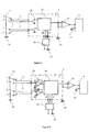
- the figure 7 presents a first exemplary embodiment of the electronics.
- the capacitance of the electrode 2 is measured by a capacimeter 7 referenced to the guard potential 34, in a totally floating manner with respect to the general mass 10.
- the guard 3 and the electrodes 2 are excited at a fixed frequency alternating voltage at circuit 7, so as to allow synchronous demodulation of the measurements.
- the floating electronics 7 is fed for example by a DC / DC voltage converter 30.
- the measurement signal after demodulation is transferred to the circuit 9 referenced to the general ground by a differential amplifier 33 to be transmitted to the calculation means.
- a multiplexer 31 makes it possible to interrogate the electrodes 2 sequentially while the inactive electrodes are held at the guard potential 34.
- the figure 8 presents a second exemplary embodiment of the electronics. It differs from that of the figure 7 in that all the electrodes 2 have their own detection electronics 35 and can be read simultaneously.
- the electronics used make it possible to measure capacitances of the order of 0.001 pF (picofarads) up to a few picofarads, with an accuracy of the order of 0.001 pF.
- the measured capacity is about 0.035 pF.
- the guard surrounding the selected electrode represents at most the totality of the detection surface 4.
- a hand can be very easily detected at more than 300 mm if the electrodes are grouped together to obtain for example an electrode surface of 2500 mm 2 . At this distance, the measured capacity is about 0.073 pF.
- the floating bridge technique implemented using an excitation of an alternating signal with modulation and amplitude demodulation also makes it possible to guarantee a very good rejection of the variation of the impedances of the dielectric materials 14 surrounding and covering the electrodes 2.
- the floating bridge has the particularity of directly measuring the inverse of the capacitance between the electrode 2 and the object 11, which makes it possible to obtain a signal linearly proportional with the distance to be measured.
- This advantage is fundamental. because, at a great distance, the capacitance varies very little with the distance (according to a hyperbolic law), and the natural offsets of the electronics and means of digitization of the signal derive more than the capacity to be measured.
- the capacitive electrodes may be electronically grouped, for example by means of the multiplexer 31, so as to constitute upper surface electrodes capable of detect objects at a greater distance.
- the electrode 44 is constituted by grouping the electrodes 40, 41, 42, 43.
- the device when the device does not detect objects in the vicinity, it is placed in a long-distance detection mode ( figure 4a ).
- the device switches to the most resolved mode laterally ( figure 4b ) to detect the details of the objects.
- the reconfiguration can be more complex, and depend locally on what is detected by the different zones.
- a device according to the invention may comprise very different electrode arrangements of a square matrix placed on a uniform surface.
- the electrodes are placed under a dielectric material 14 whose detection surface 4 mimics the shape of electromechanical switches such as rotating knobs 20 and push buttons 21.
- the "pseudo buttons" are provided with electrodes 2 making it possible to detect the approach then the action of a user.
- the figure 6 illustrates an interface consisting of capacitive electrodes disposed beneath a detection surface of flexible dielectric material, of hemispherical shape.
- Such an interface can for example easily detect which side a hand approaches, whether it is a right or left hand, or several hands ( figure 6a ), to interpret an order made with a finger ( figure 6b ) or several fingers ( Figure 6c ).
- the capacitive electrodes and the guard can be made using transparent conductive materials such as ITO (tin doped indium oxide), so that the device is substantially transparent and can be placed on a display screen for example.
- transparent conductive materials such as ITO (tin doped indium oxide)
Abstract
La présente invention concerne un dispositif d'interface de commande sensible à un mouvement d'un corps ou d'un objet, comprenant (i) une surface de détection (4), (ii) au moins un capteur capacitif, lequel ou lesquels capteur(s) comprend chacun une électrode de mesure (2) comportant une surface active orientée vers la surface de détection (4), ou sensiblement confondue avec ladite surface de détection, (iii) des moyens électroniques d'excitation et de traitement (7, 9, 12) pour exciter les électrodes de mesure (2) à un potentiel électrique alternatif et traiter les signaux issus desdits capteurs capacitifs, de façon à fournir une information de distance (13) entre la surface active des électrodes (2) et un ou plusieurs objet(s) (11), (iv) une garde en matériau conducteur à l'électricité (3) disposée à proximité des électrodes de mesure (2) au moins selon leur face sensiblement opposée à la surface active, laquelle garde (3) est excitée à un potentiel électrique alternatif sensiblement identique à celui des électrodes de mesure (2), dans lequel les électrodes de mesure (2) et la garde (3) sont réalisées au moyen de matériaux conducteurs sensiblement transparents, et le dispositif d'interface de commande est sensiblement transparent. L'invention concerne aussi un procédé mis en oeuvre dans ce dispositif et un équipement de commande.The present invention relates to a control interface device responsive to a movement of a body or an object, comprising (i) a detection surface (4), (ii) at least one capacitive sensor, which sensor (s) (s) each comprises a measuring electrode (2) having an active surface oriented towards the detection surface (4), or substantially coincident with said detection surface, (iii) electronic excitation and processing means (7, 9, 12) for exciting the measuring electrodes (2) at an alternating electric potential and processing the signals from said capacitive sensors, so as to provide distance information (13) between the active surface of the electrodes (2) and one or a plurality of object (s) (11), (iv) a guard made of electrically conductive material (3) arranged near the measuring electrodes (2) at least in their face substantially opposite to the active surface, which guard (3) ) is excited at an electrical potential that alternating substantially identical to that of the measuring electrodes (2), wherein the measuring electrodes (2) and the guard (3) are made by means of substantially transparent conductive materials, and the control interface device is substantially transparent . The invention also relates to a method implemented in this device and control equipment.
Description
La présente invention concerne un dispositif d'interface de commande, notamment gestuelle et/ou tactile possiblement combinée à une commande vocale, sensible à un mouvement d'un corps ou d'un objet ou de la voix. Elle vise également un procédé d'interface de commande mis en oeuvre dans ce dispositif, ainsi qu'un équipement de commande mettant en oeuvre un tel dispositif.The present invention relates to a command interface device, including gesture and / or tactile possibly combined with a voice command, sensitive to a movement of a body or an object or voice. It also relates to a control interface method implemented in this device, as well as control equipment implementing such a device.
Le domaine de l'invention est plus particulièrement, mais de manière non limitative, celui des interfaces homme-machine, gestuelles et/ou tactiles, et possiblement vocale permettant en temps réel d'interpréter des mouvements du corps, de la main, du doigt ou d'un objet, à grande distance jusqu'au toucher, ces mouvements étant combinés ou non à une requête vocale afin d'exécuter une ou des commandes.The field of the invention is more particularly, but in a nonlimiting manner, that of human-machine, gestural and / or tactile interfaces, and possibly vocal, allowing in real time to interpret movements of the body, the hand, the finger or an object, at a great distance to the touch, these movements being combined or not with a voice request in order to execute one or more commands.
Les interfaces hommes-machines dites virtuelles, c'est à dire gestuelles et/ou tactiles et vocale, par opposition aux interfaces ou l'utilisateur agit sur des capteurs mécaniques tels que des touches de clavier ou des commutateurs, sont le plus souvent des cameras 3D lorsqu'il s'agit d'interface gestuelle et des surfaces actives, souvent transparentes et intégrées sur des écrans d'affichage lorsqu'il s'agit d'interface tactile. Ces interfaces tactiles sont largement répandues sous le nom de « touchpad » pour de multiples applications industrielles et grand public, comme par exemple sur les smartphones, en domotique ou les interfaces de jeux.Man-machine interfaces called virtual, ie gestural and / or tactile and vocal, as opposed to interfaces where the user acts on mechanical sensors such as keyboard keys or switches, are most often cameras 3D when it comes to gesture interface and active surfaces, often transparent and integrated on display screens when it comes to touch interface. These tactile interfaces are widely used as "touchpad" for multiple industrial and consumer applications, such as smartphones, home automation or gaming interfaces.
L'écran permet d'afficher par exemple un clavier ou l'interface d'un logiciel dont l'image évolue en réponse aux actions de l'utilisateur, qui consistent en général en un déplacement, un tapotement ou encore un contact prolongé du doigt ou d'un stylet sur la surface de l'écran afin d'exécuter des commandes. Plus récemment se sont développées les interfaces dites gestuelles pour répondre à la complexité de plus en plus grande des produits numériques issus de la convergence des technologies de l'information de la communication et du divertissement. Ces interfaces sont le plus souvent à base d'une camera 3D et d'un traitement d'image capable d'interpréter à grande distance, jusqu'à 5 mètres, les mouvements du corps ou de la main pour interagir avec l'écran.The screen makes it possible to display, for example, a keyboard or the interface of software whose image evolves in response to the user's actions, which generally consist of moving, tapping or prolonged contact with the finger. or a stylus on the surface of the screen to execute commands. More recently, so-called gestural interfaces have been developed to respond to the increasing complexity of digital products resulting from the convergence of information technologies in communication and entertainment. These interfaces are the more often based on a 3D camera and image processing capable of interpreting movements of the body or the hand to interact with the screen at a distance of up to 5 meters.
Parmi les commandes virtuelles il faut aussi citer la commande vocale qui permet l'exécution d'une requête à partir de la voix.Among the virtual commands must also be mentioned voice command that allows the execution of a request from the voice.
Parmi les technologies tactiles existantes, les technologies capacitives sont fréquemment utilisées car :
- elles ne nécessitent pas d'exercer une action mécanique sur la surface de l'écran contrairement à des techniques résistives par exemples,
- elles se prêtent bien au maillage de la surface de l'écran par un réseau de capteurs directement intégré à la surface de ce dernier, ce qui permet une intégration bien plus compacte et robuste qu'avec des techniques optiques par exemple qui nécessitent un réseau d'émetteurs-récepteurs surélevés par rapport à la surface de détection.
- they do not require to exert a mechanical action on the surface of the screen unlike resistive techniques for example,
- they lend themselves well to the mesh of the screen surface by a sensor network directly integrated on the surface of the latter, which allows a much more compact and robust integration with optical techniques for example which require a network of transceivers raised above the detection surface.
De plus en plus, on recherche dans les interfaces virtuelles une fonction de détection de proximité, qui permet de créer de nouveaux modes d'interaction homme-machine sans aucun contact. Les capteurs doivent alors être en mesure de détecter des déplacements ou des formes à plusieurs centimètres, de manière suffisamment précise et résolue pour pouvoir les transformer en commandes.Increasingly, virtual interfaces are being searched for a proximity detection function, which allows the creation of new modes of human-machine interaction without any contact. The sensors must then be able to detect displacements or shapes to several centimeters, sufficiently accurately and resolutely to be able to transform them into commands.
Si les technologies optiques sont incontournables quand il s'agit de détecter précisément les mouvements à très grande distance (au delà de 40 centimètres), les technologies capacitives s'avèrent très bien adaptées pour les interfaces sans contact de proximité, notamment parce que l'ensemble des capteurs peut être intégré à une surface active non plane, par exemple un écran, sans zone morte ou sans nécessiter de dispositifs externes (caméras).While optical technologies are essential when it comes to accurately detecting movements at a great distance (beyond 40 centimeters), capacitive technologies are very well suited for contactless proximity interfaces, especially because the all of the sensors can be integrated with a non-planar active surface, for example a screen, without a dead zone or without the need for external devices (cameras).
Parmi les interfaces tactiles capacitives, les techniques les plus utilisées sont en général basées sur le principe du transfert de charges. Elles permettent d'obtenir une sensibilité de l'ordre du picofarad mais ne sont pas adaptées pour réaliser une interface gestuelle. En effet, leur sensibilité ne permet pas de détecter l'approche d'un doigt car la capacité générée ne dépasse alors pas quelques centièmes de picofarads. Les capacités parasites présentes dans ce type de capteur et dans l'électronique empêchent toute amélioration de la sensibilité.Among the capacitive touch interfaces, the most used techniques are generally based on the principle of charge transfer. They make it possible to obtain a sensitivity of the order of the picofarad but are not adapted to realize a gestural interface. Indeed, their sensitivity does not detect the approach of a finger because the generated capacity does not exceed a few hundredths of picofarads. The parasitic capacitances present in this type of sensor and in the electronics prevent any improvement of the sensitivity.
De plus, ces techniques sont très sensibles aux perturbations électromagnétiques, aux charges électriques parasites et à la conduction électrique du diélectrique recouvrant les électrodes. Lorsque l'humidité relative de l'air est supérieure à 60%, la plupart des diélectriques deviennent légèrement conducteurs d'électricité et les charges générées par l'électronique sont modifiées, ce qui perturbe la mesure capacitive.In addition, these techniques are very sensitive to electromagnetic disturbances, parasitic electric charges and electrical conduction of the dielectric covering the electrodes. When the relative humidity of the air is greater than 60%, most of the dielectrics become slightly electrically conductive and the charges generated by the electronics are modified, which disturbs the capacitive measurement.
Parmi les solutions techniques employées pour réaliser des interfaces non tactiles capacitives, on en connait qui mettent en oeuvre une pseudo-garde permettant de réduire fortement les capacités parasites dans le capteur et l'électronique. Ces techniques permettent toutefois de ne gagner au mieux qu'un ordre de grandeur sur la sensibilité, ce qui permet de détecter la présence d'un doigt à seulement quelques mm de la surface sensible du capteur.Among the technical solutions used to make non-touch capacitive interfaces, it is known that implement a pseudo-guard to greatly reduce parasitic capacitances in the sensor and electronics. These techniques, however, make it possible to gain at best only an order of magnitude on the sensitivity, which makes it possible to detect the presence of a finger only a few mm from the sensitive surface of the sensor.
En ce qui concerne les interfaces gestuelles capacitives, On connait le document
L'inconvénient de cette méthode est que l'électronique génère par principe physique des capacités parasites qui correspondent à la somme des capacités d'entrée de l'amplificateur pour générer la garde active, appelée aussi pseudo garde, et du circuit pour exciter l'électrode de mesure. Ces capacités parasites atteignent facilement le picofarad et se rajoutent à la capacité à mesurer, qui peut ne représenter que le centième de cette valeur totale.The disadvantage of this method is that the electronics generates by physical principle parasitic capacitances which correspond to the sum of the input capacitances of the amplifier to generate the active guard, also called pseudo guard, and the circuit to excite the measuring electrode. These parasitic capacitances easily reach the picofarad and are added to the capacity to measure, which can represent only one hundredth of this total value.
De plus, la mesure de la capacité n'est pas directe car l'électronique de Vranish obtient l'image de la capacité à mesurer en mesurant son courant via une résistance de référence. Cette résistance génère un déphasage parasite du courant électrique qui dégrade fortement la qualité de détection ou de démodulation du signal représentant la capacité à mesurer. Un autre inconvénient est le niveau de diaphonie entre les différentes électrodes. En effet, chaque électrode est excitée par un amplificateur opérationnel dont le gain est approximativement unitaire. Le moindre écart de gain entre les différents amplificateurs provoque une importante capacité parasite supplémentaire.In addition, the measurement of the capacitance is not direct because Vranish's electronics obtain the image of the capacity to measure by measuring its current via a reference resistance. This resistance generates a parasitic phase shift of the electric current which strongly degrades the quality of detection or demodulation of the signal representing the capacity to be measured. Another disadvantage is the level of crosstalk between the different electrodes. Indeed, each electrode is excited by an operational amplifier whose gain is approximately unitary. The slightest difference in gain between the different amplifiers causes a large additional parasitic capacitance.
Ces inconvénients ne permettent pas de détecter et de repérer la position d'un objet comme un doigt ou une main à plusieurs centimètres voire dizaines de centimètres avec chaque capteur.These disadvantages do not allow to detect and locate the position of an object as a finger or a hand to several centimeters or tens of centimeters with each sensor.
Par ailleurs, les technologies capacitives mises en oeuvre pour la réalisation d'interfaces gestuelles ont été développées le plus souvent dans le but d'être intégrées à des écrans ou du moins des surfaces sensiblement planes. Les structures de capteurs sont matricielles, comme dans
En particulier, elles sont difficilement applicables à des dispositifs de commandes virtuelles ou des interfaces gestuelles basés non pas sur une surface plane instrumentée mais sur d'autres types de géométries incluant des cavités, des reliefs, des ondulations simulant par exemple des touches, des boutons ou enveloppant l'utilisateur dans lesquels des capteurs peuvent être disposés selon des géométries diverses, parfois sous des matériaux diélectriques d'épaisseur importante, et doivent parfois pouvoir être disposés et gérés indépendamment les uns des autres.In particular, they are hardly applicable to virtual control devices or gestural interfaces based not on an instrumented planar surface but on other types of geometries including cavities, reliefs, ripples simulating for example keys, buttons or wrapping the user in which sensors may be arranged in various geometries, sometimes under thick dielectric materials, and may sometimes be arranged and managed independently of each other.
On connaît le document
Toutefois, ce dispositif, destiné à équiper des parois d'instruments mobiles, est spécifiquement conçu pour couvrir les applications d'anticollision, et ne couvre pas les applications d'interface gestuelle.However, this device, intended to equip mobile instrument walls, is specifically designed to cover anti-collision applications, and does not cover gesture interface applications.
Si les interfaces gestuelles sont amenées à prendre une grande importance, le toucher demeure toutefois très important, même dans les interfaces virtuelles capables de détecter les mouvements à distance, pour des raisons notamment psychologiques et de sécurité. En effet, d'une part la sensation tactile contribue au confort de l'utilisateur, d'autre part le toucher permet une validation des ordres efficace dans des contextes d'utilisation où la sécurité est importante (équipements médicaux, véhicules).Although gestural interfaces are very important, touch is still very important, even in virtual interfaces capable of detecting movements at a distance, for psychological and security reasons. Indeed, on the one hand the tactile sensation contributes to the comfort of the user, on the other hand the touch allows an order validation effective in contexts of use where safety is important (medical equipment, vehicles).
Le but de la présente invention est de proposer une interface gestuelle et une interface gestuelle et tactile, composées d'un dispositif et un procédé pour le contrôle d'actions et la saisie de commandes, qui soit compact et intégrable dans une grande variété d'environnements, tout en permettant :
- d'anticiper des actions par des mesures précises de déplacements sans contact, et
- de valider de manière sécurisée des ordres par détection d'actions physiques sur une surface.
- to anticipate actions by precise measurements of contactless displacements, and
- to securely validate orders by detecting physical actions on a surface.
Cet objectif est atteint avec un dispositif d'interface de commande sensible à un mouvement d'un corps ou d'un objet, comprenant :
- une surface de détection,
- au moins un capteur capacitif, lequel ou lesquels capteur(s) comprenant chacun une électrode de mesure comportant une surface active orientée vers la surface de détection, ou sensiblement confondue avec ladite surface de détection,
- une garde en matériau conducteur à l'électricité disposée à proximité des électrodes de mesure au moins selon leur face sensiblement opposée à la surface active, laquelle garde étant excitée à un potentiel électrique alternatif sensiblement identique à celui des électrodes de mesure,
- des moyens électroniques pour exciter les électrodes de mesure et traiter les signaux issus desdits capteurs capacitifs, de façon à fournir une information de distance entre la surface active des électrodes et ledit objet.
- a detection surface,
- at least one capacitive sensor, which sensor (s) each comprising a measurement electrode comprising an active surface oriented towards the detection surface, or substantially coinciding with said detection surface,
- a guard in electrically conductive material disposed near the measuring electrodes at least in their face substantially opposite to the active surface, which guard being excited at an alternating electric potential substantially identical to that of the measuring electrodes,
- electronic means for exciting the measurement electrodes and processing the signals from said capacitive sensors, so as to provide distance information between the active surface of the electrodes and said object.
Suivant l'invention,
- les surfaces actives des électrodes de mesure sont indépendantes les unes des autres, et
- les moyens électroniques d'excitation et de traitement sont en outre agencés pour interroger lesdites électrodes de mesure indépendamment les unes des autres.
- the active surfaces of the measuring electrodes are independent of each other, and
- the electronic excitation and processing means are further arranged to interrogate said measurement electrodes independently of one another.
Avantageusement, les moyens électroniques d'excitation et de traitement peuvent présenter une étendue de mesure permettant à la fois :
- de détecter et identifier un mouvement relatif du corps ou de l'objet par rapport à la surface active des électrodes de mesure, et
- de détecter un contact dudit corps ou dudit objet avec la surface de détection.
- detecting and identifying a relative movement of the body or object with respect to the active surface of the measurement electrodes, and
- detecting a contact of said body or said object with the detection surface.
L'espace de détection est défini comme la portion de l'espace dans laquelle les capteurs capacitifs sont aptes à détecter un objet et en mesurer la distance.The detection space is defined as the portion of the space in which the capacitive sensors are able to detect an object and to measure the distance.
Les objets détectables avec un dispositif selon l'invention sont des objets détectables de manière capacitive, c'est-à-dire sensiblement conducteurs d'électricité et aptes à constituer une masse électrique. Ces objets ne sont pas nécessairement reliés à la masse par une connexion électrique, mais ils peuvent l'être naturellement par couplage capacitif. On peut citer, à titre d'exemples non limitatifs, un être vivant, une main, un doigt, ou un stylet en matériau conducteur tenu à la main.The objects detectable with a device according to the invention are capacitively detectable objects, that is to say substantially electrically conductive and able to constitute an electrical mass. These objects are not necessarily grounded by an electrical connection, but they can be naturally connected by capacitive coupling. By way of nonlimiting examples, there may be mentioned a living being, a hand, a finger, or a stylet made of conductive material held by hand.
Le dispositif selon l'invention permet de mesurer à chaque instant la forme de la surface du corps ou de l'objet relativement à la position des capteurs capacitifs. La détection du mouvement d'un objet ou d'un corps peut ainsi inclure, de manière non limitative, sa position dans l'espace, sa trajectoire, et l'analyse de sa forme à des fins d'identification par exemple.The device according to the invention makes it possible to measure at any moment the shape of the surface of the body or of the object relative to the position of the capacitive sensors. The detection of the movement of an object or a body can thus include, without limitation, its position in space, its trajectory, and the analysis of its shape for identification purposes for example.
Avantageusement, les moyens électroniques d'excitation et de traitement peuvent au moins pour partie être référencés au potentiel électrique de la garde.Advantageously, the electronic excitation and processing means may at least partly be referenced to the electrical potential of the guard.
Cette configuration de l'électronique, en pont flottant, permet de supprimer les capacités parasites. Ainsi, les capacités mesurées par chaque capteur sont directement celles créées entre l'objet visé et les électrodes. La sensibilité du dispositif est optimisée et permet une mesure à grande distance très résolue. De plus, les capteurs capacitifs et l'électronique associée peuvent alors être optimisés pour atteindre une étendue de mesure, ou dynamique, importante. En effet, la gamme de capacités à mesurer avec chaque électrode peut s'étendre de moins d'un millième de picofarad à plusieurs picofarads, soit une dynamique en termes de capacités supérieure à 1000. Cette dynamique permet de détecter, avec sensiblement la même résolution latérale liée à la taille de l'électrode, la présence ou la position d'un objet lointain comme un doigt à plus de 5 cm de distance ainsi que le contact et la pression de ce doigt par exemple sur un diélectrique recouvrant l'électrode de mesure. De cette manière, le dispositif selon l'invention permet à la fois d'anticiper des actions par identification de l'objet qui approche ou de son mode d'approche, et de valider des commandes par détection du contact.This configuration of the electronics, in floating bridge, makes it possible to suppress the parasitic capacitances. Thus, the capacitances measured by each sensor are directly those created between the target object and the electrodes. The sensitivity of the device is optimized and allows a very long distance measurement very resolute. In addition, the capacitive sensors and the associated electronics can then be optimized to reach a measurement range, or dynamic, important. In fact, the range of capacitances to be measured with each electrode can range from less than one thousandth of picofarad to several picofarads, ie a dynamic in terms of capacities greater than 1000. This dynamic makes it possible to detect, with substantially the same resolution lateral view related to the size of the electrode, the presence or position of a distant object such as a finger more than 5 cm apart as well as the contact and the pressure of this finger for example on a dielectric covering the electrode of measured. In this way, the device according to the invention makes it possible both to anticipate actions by identifying the approaching object or its mode of approach, and to validate commands by contact detection.
Suivant un autre aspect avantageux du dispositif selon l'invention, chaque capteur capacitif comprend une seule électrode de mesure qui est indépendante des électrodes des autres capteurs. Il est ainsi possible de disposer les électrodes selon des géométries et des formes de surfaces très variées. Ce caractère indépendant des électrodes est un aspect particulièrement avantageux du dispositif selon l'invention pour la réalisation d'interfaces gestuelles basées sur des structures de formes quelconques, et en ce sens, il diffère des interfaces gestuelles de l'art antérieur basées sur des structures matricielles de capteurs disposées sur des surfaces planes ou des écrans.According to another advantageous aspect of the device according to the invention, each capacitive sensor comprises a single measuring electrode which is independent of the electrodes of the other sensors. It is thus possible to arrange the electrodes in a variety of geometries and surface shapes. This independent character of the electrodes is a particularly advantageous aspect of the device according to the invention for the production of gestural interfaces based on structures of any shape, and in this sense, it differs from the gestural interfaces of the prior art based on structures. matrix of sensors arranged on flat surfaces or screens.
Suivant des modes de réalisation particuliers, les moyens électroniques d'excitation et de traitement peuvent comprendre des moyens de scrutation permettant de lire séquentiellement les signaux de mesure issus des capteurs capacitifs. Les électrodes qui ne sont pas en cours de scrutation peuvent avantageusement être reliées au potentiel de la garde.According to particular embodiments, the electronic excitation and processing means may comprise scanning means for sequentially reading the measurement signals from the capacitive sensors. The electrodes that are not being scanned can advantageously be connected to the potential of the guard.
Dans ce mode de réalisation, les électrodes sont sélectionnées séquentiellement afin de limiter le nombre de composants et la consommation d'énergie. Le fait de relier au potentiel de garde les électrodes qui ne sont pas en cours de scrutation permet de réduire au maximum les effets de bord électrostatique de l'électrode mesurante.In this embodiment, the electrodes are selected sequentially to limit the number of components and the power consumption. The fact of connecting the electrodes that are not being scanned to the guard potential makes it possible to minimize the electrostatic edge effects of the measuring electrode.
Suivant d'autres modes de réalisation nécessitant plus de composants, chaque électrode peut être reliée à un circuit électronique comme par exemple un amplificateur de charge. Ces circuits électroniques sont référencés au potentiel électrique flottant, donc à celui de la garde, ce qui permet de conserver la propriété avantageuse que chaque électrode est vue comme une garde pour ses voisines. Cette solution permet d'augmenter la vitesse de mesure car les capacités ou distances peuvent être mesurées en parallèle sur toutes les électrodes.According to other embodiments requiring more components, each electrode may be connected to an electronic circuit such as a charge amplifier. These electronic circuits are referenced to the floating electrical potential, therefore to that of the guard, which allows to retain the advantageous property that each electrode is seen as a guard for its neighbors. This solution makes it possible to increase the measurement speed because the capacitances or distances can be measured in parallel on all the electrodes.
Il est bien entendu possible de mettre en oeuvre d'autres modes de scrutation des électrodes, tel que par exemple une lecture par groupe.It is of course possible to implement other electrode scanning modes, such as for example a group reading.
Suivant des modes de réalisation particuliers, les moyens électroniques d'excitation et de traitement peuvent comprendre des moyens permettant de regrouper électriquement des électrodes de mesure, de telle sorte que lesdites électrodes regroupées constituent une électrode de mesure unique.According to particular embodiments, the electronic excitation and processing means may comprise means for electrically grouping measuring electrodes, so that said grouped electrodes constitute a single measuring electrode.
Il est ainsi possible de créer des électrodes de surface supérieure, permettant d'augmenter l'étendue de mesure pour détecter des objets à une plus grande distance. La configuration des groupements d'électrodes peut bien entendu être effectuée électroniquement, et être contrôlée par les moyens de calcul. Les électrodes de mesure peuvent par exemple être regroupées lorsque l'objet est loin du panneau afin de privilégier la portée de mesure, et dégroupées lorsque l'objet est proche des électrodes afin de favoriser la résolution spatiale et la précision de la position en trois dimensions de l'objet.It is thus possible to create upper surface electrodes, making it possible to increase the measurement range to detect objects at a greater distance. The configuration of the electrode groups can of course be performed electronically, and be controlled by the calculation means. The measurement electrodes can for example be grouped together when the object is far from the panel in order to favor the measurement range, and unbundled when the object is close to the electrodes in order to promote the spatial resolution and the accuracy of the three-dimensional position. of the object.
Avantageusement,
- la surface des électrodes peut être calculée de telle sorte que chaque capteur capacitif puisse mesurer la distance entre la surface active de l'électrode et un doigt jusqu'à une distance d'au moins 3 cm, ou, suivant les applications, 5 cm ;
- les électrodes de mesures peuvent être réalisées sur un support de type circuit imprimé souple. Ainsi, elles peuvent être réalisées selon des techniques de réalisation de circuits électroniques classiques, et être disposées selon des surfaces ou des ensembles de surfaces qui ne sont pas nécessairement plans,
- les électrodes de mesures peuvent également être réalisées sur un support de type circuit imprimé rigide,
- les moyens électroniques d'excitation et de traitement référencés au potentiel de la garde peuvent être fixés sur le même support que les électrodes.
- the surface of the electrodes can be calculated so that each capacitive sensor can measure the distance between the active surface of the electrode and a finger up to a distance of at least 3 cm, or depending on the application, 5 cm;
- the measurement electrodes can be made on a support of the flexible printed circuit type. Thus, they can be produced according to techniques for producing conventional electronic circuits, and can be arranged according to surfaces or sets of surfaces that are not necessarily planar,
- the measuring electrodes can also be made on a rigid printed circuit type support,
- the electronic excitation and processing means referenced to the potential of the guard can be fixed on the same support as the electrodes.
Le fait qu'une partie de l'électronique soit référencée au potentiel de la garde permet avantageusement de la placer à proximité des électrodes sans risquer de perturber leur fonctionnement, et améliore ainsi les conditions d'intégration du dispositif. En effet, si ces circuits électriques étaient référencés par exemple au potentiel de masse extérieur (potentiel proche de celui de l'objet ou du doigt), les lignes de champ des électrodes seraient très rapidement absorbées par ces circuits et la portée du dispositif ne permettrait pas de réaliser une détection sans contact. C'est un problème majeur rencontré dans beaucoup de dispositifs de l'art antérieur.The fact that part of the electronics is referenced to the potential of the guard advantageously makes it possible to place it close to the electrodes without the risk of disturbing their operation, and thus improves the conditions of integration of the device. Indeed, if these electrical circuits were referenced for example to the external ground potential (potential close to that of the object or the finger), the field lines of the electrodes would be very quickly absorbed by these circuits and the scope of the device would not allow not to perform contactless detection. This is a major problem encountered in many devices of the prior art.
Avantageusement, la partie de l'électronique référencée à la garde peut communiquer avec des systèmes extérieurs en utilisant la masse de référence de ces systèmes extérieurs. La liaison et le découplage entre l'électronique capacitive et l'extérieur peuvent par exemple être réalisés au moyen d'optocoupleurs ou de selfs (inductances) de choc. L'alimentation de la partie flottante référencée à la garde peut être réalisée avec un convertisseur DC-DC ou des selfs de choc.Advantageously, the part of the electronics referenced to the guard can communicate with external systems by using the reference mass of these external systems. The connection and the decoupling between the capacitive electronics and the outside can for example be carried out by means of optocouplers or shock inductors. The supply of the floating part referenced to the guard can be performed with a DC-DC converter or shock chokes.
Suivant un autre aspect de l'invention, le dispositif peut comprendre en outre un matériau diélectrique disposé du côté de la surface active des électrodes de mesure. Dans ce cas, la surface dudit matériau diélectrique opposée aux électrodes constitue la surface de détection.According to another aspect of the invention, the device may further comprise a dielectric material disposed on the active surface side of the measurement electrodes. In this case, the surface of said dielectric material opposite the electrodes constitutes the detection surface.
Avantageusement,
- le matériau diélectrique peut être disposé de telle sorte à être sensiblement en contact avec la surface active des électrodes,
- le matériau diélectrique peut comprendre un matériau souple permettant à la surface de détection de se déformer sensiblement en direction des électrodes de mesure par amincissement local du matériau sous l'action d'une force d'appui.
- the dielectric material may be arranged so as to be substantially in contact with the active surface of the electrodes,
- the dielectric material may comprise a flexible material allowing the detection surface to deform substantially towards the measuring electrodes by local thinning of the material under the action of a bearing force.
Le fait d'utiliser un matériau souple permet avantageusement de détecter la pression exercée sur la surface par mesure du déplacement de l'objet en deçà de la position de la surface de détection au repos.The fact of using a flexible material advantageously makes it possible to detect the pressure exerted on the surface by measuring the displacement of the object below the position of the detection surface at rest.
Suivant un autre mode de réalisation, le matériau diélectrique peut comprendre une plaque sensiblement rigide, apte à se déplacer vers des électrodes de mesure sous l'action d'une force d'appui, selon une inclinaison dépendant du point d'application de ladite force d'appui.According to another embodiment, the dielectric material may comprise a substantially rigid plate, able to move towards measurement electrodes under the action of a bearing force, at an inclination depending on the point of application of said force. support.
La plaque peut être pourvue d'électrodes détectables de manière capacitive sur au moins une partie de sa surface, de telle sorte à pouvoir en mesurer le déplacement ou la déformation au moyen d'électrodes capacitives judicieusement placées. Cette plaque peut être par exemple un clavier soumis à la pression d'un objet ou d'un doigt. Avec au moins deux électrodes capacitives disposées vis-à-vis d'électrodes de la plaque et mesurant la distance à ces électrodes, il est possible de mesurer l'inclinaison du clavier et d'estimer la zone approximative où le doigt appuie.The plate may be provided with capacitively detectable electrodes on at least a portion of its surface so that displacement or deformation thereof can be measured by appropriately placed capacitive electrodes. This plate can be for example a keyboard subjected to the pressure of an object or a finger. With at least two capacitive electrodes arranged opposite electrodes of the plate and measuring the distance to these electrodes, it is possible to measure the inclination of the keyboard and to estimate the approximate area where the finger presses.
Suivant une autre configuration, un ensemble, par exemple un clavier, comprenant une plaque diélectrique recouvrant de premières électrodes de mesure, peut être apte à se déplacer globalement sous l'effet de la pression vers de secondes électrodes de mesures, qui mesurent cette pression.According to another configuration, an assembly, for example a keyboard, comprising a dielectric plate covering first electrodes of measurement, may be able to move globally under the effect of pressure to second measurement electrodes, which measure this pressure.
Avantageusement, ces secondes électrodes peuvent être de sensibilité optimisée pour les faibles déplacements.Advantageously, these second electrodes can be of optimized sensitivity for small displacements.
Avantageusement,
- le matériau diélectrique peut être sélectionné de telle sorte à présenter une texture agréable au toucher,
- la surface de détection peut présenter des formes en relief matérialisant des commandes.
- the dielectric material can be selected so as to have a texture that is pleasant to the touch,
- the detection surface may have raised shapes embodying commands.
La surface de détection peut être plane, mais aussi d'une forme quelconque permettant une intégration optimale en termes d'esthétique et d'ergonomie notamment. Elle peut être, par exemple et de manière non limitative, de forme sphérique ou hémisphérique pour imiter une souris d'ordinateur ou une partie d'un tableau de commande d'une machine médicale.The detection surface may be flat, but also of any shape allowing optimal integration in terms of aesthetics and ergonomics in particular. It may be, for example and without limitation, spherical or hemispherical to imitate a computer mouse or part of a control panel of a medical machine.
Un dispositif selon l'invention peut être intégré selon une grande variété de configurations, par exemple à un accoudoir de fauteuil pour personnes handicapées, ou au tableau de bord d'un véhicule. Il permet en particulier de remplacer des boutons électromécaniques de commande, pour des raisons de fiabilité par exemple.A device according to the invention can be integrated in a wide variety of configurations, for example a chair armrest for the disabled, or the dashboard of a vehicle. In particular, it makes it possible to replace electromechanical control buttons, for reasons of reliability for example.
Sans perte de généralité, on peut assimiler la surface de détection à un panneau de commande. De préférence, les électrodes de mesure sont juxtaposées les unes aux autres afin d'éviter des zone mortes, dans lesquelles les objets ne sont pas détectés, sur le panneau. On peut aussi créer volontairement des zones mortes dans lesquelles l'électrode est remplacée par une garde ou une masse, ce qui permet de dévier les lignes de champ des électrodes voisines pour en réduire la portée ou les modifier.Without loss of generality, the detection surface can be likened to a control panel. Preferably, the measurement electrodes are juxtaposed to each other in order to avoid dead zones, in which the objects are not detected, on the panel. It is also possible to deliberately create dead zones in which the electrode is replaced by a guard or a mass, which makes it possible to deflect the field lines of the neighboring electrodes in order to reduce their range or to modify them.
Afin d'obtenir un bon compromis entre la résolution latérale et la portée de détection de l'objet, il est avantageux de choisir une taille d'électrodes sensiblement du même ordre de grandeur que celle de l'objet. Par exemple pour optimiser la détection d'un doigt, il est avantageux de choisir une surface d'électrode de l'ordre de 1 cm2 à 2 cm2.In order to obtain a good compromise between the lateral resolution and the detection range of the object, it is advantageous to choose an electrode size of substantially the same order of magnitude as that of the object. For example to optimize the detection of a finger, it is advantageous to choose an electrode surface of the order of 1 cm 2 to 2 cm 2 .
La forme des électrodes peut être adaptée en fonction des caractéristiques de détection recherchées, et plusieurs formes d'électrodes peuvent exister dans un même dispositif. Par exemple, il est possible de disposer des électrodes de forme particulière, par exemple rectangulaire, sur les bords d'un panneau de commande pour détecter de quel côté s'approche un doigt ou une main. Cela peut permettre par exemple au dispositif de sélectionner les actions autorisées pour une personne, selon le côté par lequel elle aborde le panneau.The shape of the electrodes can be adapted according to the desired detection characteristics, and several forms of electrodes can exist in the same device. For example, it is possible to have electrodes of particular shape, for example rectangular, on the edges of a control panel to detect which side approaches a finger or a hand. This may allow for example the device to select the actions authorized for a person, depending on the side by which it approaches the panel.
Un dispositif selon l'invention peut fournir comme données de sorties, de manière non limitative, soit des signaux de mesure analogiques, soit des signaux sous forme numérique, soit directement les distances séparant les électrodes de l'objet ou soit directement, par exemple, la position en trois dimensions, l'analyse des mouvements de l'objet, l'identification de l'objet ou des ordres de commande.A device according to the invention can provide as output data, in a nonlimiting manner, either analog measurement signals, or signals in digital form, or directly the distances separating the electrodes of the object or directly, for example, the three-dimensional position, the analysis of the movements of the object, the identification of the object or orders.
Pour une détection en trois dimensions, chaque électrode du dispositif peut être considérée comme un pixel et la résolution spatiale physique est limitée par la surface des électrodes. Cette résolution spatiale peut être sensiblement améliorée au moyen de méthodes de calcul numérique d'interpolation. Une méthode consiste par exemple à calculer le centre de gravité de l'objet « vu » par l'ensemble des électrodes. Ce centre théorique devient un point virtuel qui peut être visualisé sur un écran. Cela permet par exemple d'écrire, de dessiner ou d'agir avec précision sur une surface réduite représentée sur un écran avec un objet tel qu'un doigt ou une main.For three-dimensional detection, each electrode of the device may be considered a pixel and the physical spatial resolution is limited by the surface of the electrodes. This spatial resolution can be substantially improved by means of numerical interpolation calculation methods. One method is for example to calculate the center of gravity of the object "seen" by all the electrodes. This theoretical center becomes a virtual point that can be viewed on a screen. This allows for example to write, draw or act accurately on a small surface represented on a screen with an object such as a finger or a hand.
La détection tridimensionnelle permet aussi d'utiliser le dispositif comme une camera capacitive. En effet le système permet de mesurer en temps réel la distance absolue séparant chaque électrode de l'objet visé et, avec un nombre suffisant d'électrodes, il est possible d'imager ou de reconnaître cet objet.Three-dimensional detection also allows the device to be used as a capacitive camera. Indeed, the system makes it possible to measure in real time the absolute distance separating each electrode from the target object and, with a sufficient number of electrodes, it is possible to image or recognize this object.
Le dispositif selon l'invention a également pour objet de détecter le contact de l'objet (ou le doigt) avec la surface de détection (ou le panneau de commande) de manière suffisamment certaine pour garantir la sûreté de fonctionnement recherchée. Pour cela, connaissant la position de la surface de détection par exemple par calibrage, il est possible de déterminer le contact directement à partir de la mesure de distance de l'objet, lorsqu'on détecte que l'objet est à une distance correspondant à celle de la surface.The device according to the invention also aims to detect the contact of the object (or the finger) with the detection surface (or the control panel) sufficiently sufficiently to ensure the desired operating safety. For this, knowing the position of the detection surface for example by calibration, it is possible to determine the contact directly from the distance measurement of the object, when it is detected that the object is at a distance corresponding to that of the surface.
Suivant un mode de réalisation avantageux selon lequel la surface de détection est constituée par un matériau diélectrique en contact avec la surface des électrodes, il est possible de détecter le contact de manière plus sûre à partir de l'analyse de la capacité entre l'objet et l'électrode. En effet, lorsqu'un doigt par exemple entre en contact avec la surface du diélectrique, il n'y a pratiquement plus d'air sur le trajet des lignes de champ électrique entre le doigt et l'électrode. Or le matériau diélectrique a une permittivité diélectrique supérieure à celle de l'air, de l'ordre par exemple de εr = 3. En conséquence, la capacité entre le doigt et l'électrode est sensiblement plus élevée lorsque le doigt est en contact avec la surface, comparé au cas où il subsiste une mince lame d'air, ce qui permet de détecter le contact de manière plus sûre.According to an advantageous embodiment according to which the detection surface is constituted by a dielectric material in contact with the surface of the electrodes, it is possible to detect the contact more safely from the analysis of the capacitance between the object. and the electrode. Indeed, when a finger for example comes into contact with the surface of the dielectric, there is virtually no air in the path of the electric field lines between the finger and the electrode. However, the dielectric material has a dielectric permittivity greater than that of air, of the order of, for example, ε r = 3. As a result, the capacitance between the finger and the electrode is substantially higher when the finger is in contact. with the surface, compared to the case where there is a thin air gap, which makes it possible to detect the contact more safely.
Il est également possible, dans un dispositif selon l'invention, que les électrodes ne soient pas recouvertes de matériau diélectrique. Dans ce cas, le contact entre l'objet et une électrode peut être détecté du fait que l'électrode est mise au potentiel électrique de masse de l'objet lors du contact.It is also possible, in a device according to the invention, that the electrodes are not covered with dielectric material. In this case, the contact between the object and an electrode can be detected because the electrode is placed at the electrical potential of the object's mass during the contact.
La pression peut avantageusement être mesurée en mesurant l'enfoncement d'un objet tel qu'un doigt dans un matériau diélectrique sensiblement souple ou mou recouvrant les électrodes. La distance mesurée est sensiblement proportionnelle à l'enfoncement du doigt dans le matériau diélectrique. De plus, la variation de distance mesurée, qui est également sensiblement proportionnelle à l'inverse de la capacité, est multipliée par la permittivité relative du diélectrique εr qui recouvre l'électrode, ce qui a pour résultat une augmentation de la sensibilité de la mesure de distance dès lors qu'il y a un contact entre le doigt ou l'objet et le diélectrique.The pressure can advantageously be measured by measuring the depression of an object such as a finger in a substantially flexible or soft dielectric material covering the electrodes. The measured distance is substantially proportional to the depression of the finger in the dielectric material. In addition, the measured distance variation, which is also substantially proportional to the inverse of the capacitance, is multiplied by the relative permittivity of the dielectric ε r which covers the electrode, which results in an increase in the sensitivity of the distance measurement when there is contact between the finger or the object and the dielectric.
Une autre solution pour mesurer la pression peut consister à mesurer l'augmentation de la capacité due à l'augmentation de la surface d'appui d'un objet tel qu'un doigt en contact avec la surface d'un matériau diélectrique relativement rigide, lorsque la pression exercée augmente.Another solution for measuring the pressure may be to measure the increase in capacity due to the increase of the bearing surface of an object such as a finger in contact with the surface of a relatively rigid dielectric material, when the pressure exerted increases.
La présente invention permet donc de détecter, sans contact et à plusieurs centimètres voire décimètres, la position d'un doigt ou d'un objet dans l'espace, de détecter le contact du doigt ou de l'objet sur une surface de détection telle qu'un panneau de commande ou un clavier par exemple, et aussi de détecter la pression exercée par le doigt ou l'objet sur cette surface. La mesure peut être effectuée au travers d'un matériau diélectrique quelconque. Ces caractéristiques permettent de créer des interfaces de contrôle très évoluées, esthétiques et ergonomiques avec des possibilités de combinaison de commandes originales.The present invention thus makes it possible to detect, without contact and at several centimeters or even decimetres, the position of a finger or an object in space, to detect the contact of the finger or the object on a detection surface such as a control panel or a keyboard for example, and also to detect the pressure exerted by the finger or the object on this surface. The measurement can be made through a dielectric material any. These features make it possible to create highly evolved, aesthetic and ergonomic control interfaces with the possibility of combining original controls.
Il est par exemple possible, de manière non limitative, de reconnaître des signes par le mouvement des doigts, de déterminer le côté de la surface active par laquelle une main est arrivée dans le but de contrôler des actions autorisées ou non par les différentes personnes se trouvant, devant l'interface et de valider une commande majeure par un effleurement ou une pression du doigt sur le clavier.For example, it is possible, in a non-limiting way, to recognize signs by the movement of the fingers, to determine the side of the active surface by which a hand has arrived in order to control actions authorized or not by the different people. finding in front of the interface and validate a major command by a touch or a fingertip on the keyboard.
L'utilisation d'un dispositif selon l'invention n'est bien entendu pas limitée à la détection d'un seul doigt, et des commandes issues des mouvements simultanés ou non de plusieurs doigts peuvent être envisagés.The use of a device according to the invention is of course not limited to the detection of a single finger, and commands from the simultaneous movements or not of several fingers can be considered.
Un dispositif selon l'invention permet de détecter la position d'un doigt au travers de tout type de diélectrique, même épais de plusieurs millimètres voire centimètres. Cet avantage permet de concevoir des dispositifs de commande avec une infinité de forme, de relief, de couleurs et de sensation de toucher permettant de les rendre plus agréables à utiliser. On peut par exemple mettre en oeuvre des matériaux de qualité comme le bois, le cuir, la céramique ou tout type de polymère rigide ou souple comme du silicone. En particulier, un matériau mou comme du silicone peut donner une sensation de toucher plus agréable.A device according to the invention can detect the position of a finger through any type of dielectric, even thick of several millimeters or even centimeters. This advantage makes it possible to design control devices with an infinity of shape, relief, colors and feel to make them more enjoyable to use. For example, it is possible to use quality materials such as wood, leather, ceramics or any type of rigid or flexible polymer such as silicone. In particular, a soft material such as silicone can give a feeling of touch more pleasant.
Avantageusement, le diélectrique peut être aisément remplacé pour des raisons d'hygiène ou d'esthétique notamment. Ce diélectrique peut être un matériau apte à être lavé ou stérilisé, ce qui rend le dispositif selon l'invention particulièrement adapté à la réalisation d'interfaces dans des environnements où l'hygiène est importante.Advantageously, the dielectric can be easily replaced for reasons of hygiene or aesthetics in particular. This dielectric may be a material capable of being washed or sterilized, which makes the device according to the invention particularly suitable for the production of interfaces in environments where hygiene is important.
L'invention peut porter également, de manière non limitative, sur :
- un équipement de commande assurant une fonction d'interface homme-machine intégrant un dispositif capacitif de détection de mouvement selon l'invention,
- un équipement de commande destiné à être intégré à un véhicule, comprenant un dispositif capacitif de détection de mouvement selon l'invention,
- une structure murale sensible intégrant un dispositif de contrôle selon l'invention.
- control equipment providing a human-machine interface function integrating a capacitive motion detection device according to the invention,
- control equipment for integration with a vehicle, comprising a capacitive motion detection device according to the invention,
- a sensitive wall structure incorporating a control device according to the invention.
Suivant un autre aspect, il est proposé un procédé d'interface de commande sensible à un mouvement d'un corps ou d'un objet, mettant en oeuvre un dispositif selon l'invention, comprenant :
- une excitation d'une ou plusieurs électrodes de mesure au sein d'au moins un capteur capacitif, lesdites électrodes de mesure (i) comportant une surface active orientée vers une surface de détection, ou sensiblement confondue avec ladite surface de détection et (ii) étant pourvues d'une garde en matériau conducteur à l'électricité disposée à proximité des électrodes de mesure au moins selon leur face sensiblement opposée à la surface active,
- une excitation de ladite garde étant à un potentiel électrique alternatif sensiblement identique à celui des électrodes de mesure,
- un traitement de signaux issus desdits capteurs capacitifs de façon à fournir une information de distance entre la surface active des électrodes et ledit objet,
- an excitation of one or more measuring electrodes within at least one capacitive sensor, said measuring electrodes (i) having an active surface oriented towards a detection surface, or substantially coinciding with said detection surface and (ii) being provided with a guard made of electrically conductive material disposed near the measuring electrodes at least in their face substantially opposite to the active surface,
- an excitation of said guard being at an alternating electric potential substantially identical to that of the measuring electrodes,
- signal processing from said capacitive sensors so as to provide distance information between the active surface of the electrodes and said object,
Dans une forme particulière de mise en oeuvre, le procédé selon l'invention qui comprend une mesure d'au moins une distance entre l'objet et la surface de détection, et un traitement desdites mesures de distance pour fournir une information d'approche, est caractérisé en ce qu'il comprend en outre :
- une mesure du contact entre l'objet et la surface de détection, et
- un traitement desdites mesures de contact pour fournir une information de toucher.
- a measurement of the contact between the object and the detection surface, and
- processing said contact measurements to provide touch information.
Le contact peut bien entendu être un effleurement de la surface.The contact can of course be a touch of the surface.
Suivant des aspects avantageux,
- la détection du contact entre l'objet et la surface de détection peut comprendre une comparaison de capacités mesurées avec au moins une valeur de seuil,
- le traitement des mesures de distances peut comprendre une détection de la position de l'objet dans l'espace obtenue au moins à partir des mesures de distances et de connaissances sur la disposition des capteurs capacitifs, et
- le traitement des mesures de contact peut comprendre une identification des capteurs capacitifs ayant détecté un contact entre l'objet et la surface de détection.
- the detection of the contact between the object and the detection surface may comprise a comparison of measured capacitances with at least one threshold value,
- the processing of the distance measurements can comprise a detection of the position of the object in the space obtained at least from the measurements of distances and knowledge on the disposition of capacitive sensors, and
- the processing of the contact measurements may comprise an identification of the capacitive sensors having detected a contact between the object and the detection surface.
Le procédé selon l'invention peut comprendre en outre :
- une mesure de déplacement de la surface de détection sous l'action de l'objet,
- un traitement desdites mesures de déplacement pour fournir une information d'appui.
- a measurement of displacement of the detection surface under the action of the object,
- processing said displacement measurements to provide supporting information.
Avantageusement,
- le procédé selon l'invention peut comprendre en outre une étape de détermination de commandes, lesquelles commandes étant conditionnées au moins par au moins l'une quelconque des informations d'approche, de toucher et d'appui,
- au moins une commande déterminée par l'une quelconque des informations de toucher et d'appui peut être conditionnée par l'information d'approche,
- au moins une commande peut être conditionnées par l'évolution temporelle d'au moins l'une quelconque des informations d'approche, de toucher et d'appui.
- the method according to the invention may further comprise a step of determining commands, which commands are conditioned at least by at least one of the approach, touch and support information,
- at least one command determined by any of the touch and support information may be conditioned by the approach information,
- at least one command may be conditioned by the temporal evolution of at least one of the approach, touch and support information.
Ainsi, le procédé selon l'invention permet de générer des commandes en prenant en compte jusqu'à trois niveaux d'information :
- des informations d'approche,
- des informations de toucher,
- des informations d'appui.
- approach information,
- touch information,
- supporting information.
Bien entendu, les trois niveaux d'informations peuvent apparaître et être traitées simultanément, et ces informations peuvent inclure l'évolution temporelle des mesures ou leur historique.Of course, the three levels of information can appear and be processed simultaneously, and this information can include the temporal evolution of the measurements or their history.
De manière non limitative,
- les informations d'approche peuvent par exemple comprendre la distance, la trajectoire, l'identification d'un ou plusieurs objets à partir de leur forme. Elles peuvent être utilisées par exemple pour adapter l'interface au mode d'action en cours : activation, éclairage sélectif, adaptation de l'interface à une utilisation par un gaucher ou un droitier, par une main ou un stylet, ...
- les informations de toucher peuvent comprendre par exemple le lieu de contact, des trajectoires simples ou simultanées sur la surface, des tapotements simples ou répétés. Elles peuvent par exemple être utilisées pour valider des commandes (boutons), entrer des données (écriture), faire défiler ou zoomer un affichage, ...
- les informations d'appui peuvent comprendre par exemple une pression en un lieu, le long d'une ou plusieurs trajectoires, des tapotements appuyés simples ou répétés, ainsi que la durée de la pression. Elles peuvent par exemple être utilisées pour effectuer des commandes proportionnelles (réglage d'une vitesse, d'une intensité), verrouiller des commandes, ...
- the approach information can for example include the distance, the trajectory, the identification of one or more objects from their shape. They can be used for example to adapt the interface to the current mode of action: activation, selective lighting, adaptation of the interface for use by a left-handed or right-handed person, by a hand or a stylus, ...
- the touching information may include, for example, the point of contact, simple or simultaneous trajectories on the surface, simple or repeated tapping. They can for example be used to validate commands (buttons), enter data (writing), scroll or zoom a display, ...
- the support information may include, for example, pressure at a location, along one or more paths, single or repeated taps, and the duration of the pressure. They can for example be used to perform proportional commands (setting a speed, an intensity), lock commands, ...
La capacité à distinguer de manière sûre l'approche et le toucher (ou l'effleurement) est fondamentale pour des interfaces destinées à des applications requérant un certain niveau de sécurité. Cela permet de répondre à une exigence de sécurité fondamentale qui pose qu'un ordre doit être sélectionné puis validé afin d'éviter les actions intempestives.The ability to confidently distinguish approach and touch (or touch) is fundamental for interfaces intended for applications requiring a certain level of security. This makes it possible to answer a fundamental security requirement which poses that an order must be selected then validated in order to avoid the untimely actions.
Avantageusement, avec le procédé et le dispositif selon l'invention, la sélection peut se faire sans contact ce qui permet un gain de souplesse considérable. La détection et l'analyse de l'approche peuvent également être utilisées pour conférer au dispositif une capacité d'anticipation ou de préparation de commandes qui peut également être un facteur de sécurité.Advantageously, with the method and the device according to the invention, the selection can be done without contact which allows considerable flexibility gain. Detection and analysis of the approach can also be used to give the device anticipation or order picking capability which can also be a safety factor.
On trouve ces exigences de sécurités notamment pour des interfaces destinées à des équipements médicaux ou à des véhicules, en particulier automobiles, pour lesquels le dispositif et le procédé selon l'invention sont particulièrement bien adaptés.These safety requirements are found especially for interfaces intended for medical equipment or vehicles, in particular motor vehicles, for which the device and the method according to the invention are particularly well suited.
Bien entendu, le dispositif et le procédé selon l'invention ne sont pas limités à des applications liées à la sécurité. De manière générale, on peut citer à titre d'exemple non limitatifs les possibilités d'applications suivantes :
- Les applications étendues de commandes tridimensionnelles en général, de contrôle ou de commande gestuelle, connues par exemple sous des noms tels que « 3D touch panel », « 3D gesture controllers », « 3D floating vision » ;
- La domotique, avec par exemple des commandes de lumière, de climatisation, de volets, d'ouverture de porte ...
- L'électroménager, pour toute sorte de commande et de programmation d'appareils tels que des machines à laver, ...
- Les interfaces utilisateur d'équipements portables, téléphones, GPS, ...
- Les interfaces utilisateur d'équipements de bureautique et d'informatique, ordinateurs, ...
- Les interfaces de jeux électroniques à commande gestuelle ;
- Les interfaces de pilotage et de contrôle de fonctions de véhicules en général, y compris dans le domaine militaire et l'aviation ;
- Extensive applications of three-dimensional commands in general, control or gesture control, known for example under names such as "3D touch panel", "3D gesture controllers", "3D floating vision";
- Home automation, for example with controls for lighting, air conditioning, shutters, door opening ...
- Appliances, for any kind of control and programming of appliances such as washing machines, ...
- User interfaces of portable equipment, telephones, GPS, ...
- User interfaces of office automation and computer equipment, computers, ...
- Gesture-controlled electronic games interfaces;
- Interface control and control of vehicle functions in general, including military and aviation;
Suivant encore un autre aspect, un dispositif selon l'invention peut être associé avec d'autres moyens de détection et/ou d'identification sans contact pour réaliser des interfaces gestuelles globales comprenant plusieurs niveaux de détection d'un utilisateur. Il est possible par exemple :
- de localiser un utilisateur, par exemple dans un habitacle de véhicule, au moyen de capteurs capacitifs à plus grande distance de mesure, ou optiques ou à ultrasons, de telle sorte à préconfigurer une interface gestuelle selon l'invention. Par exemple, certaines fonctions peuvent être configurées différemment selon la position et le nombre d'occupants ;
- d'identifier, par exemple avec une caméra et des moyens de reconnaissances d'images, des mouvements et/ou des caractéristiques d'un utilisateur (genre, habillement, identité, morphologie ou toutes autres caractéristiques ...) de telle sorte à adapter l'interface gestuelle à ses besoins ou, pour des applications de contrôle d'accès, à son niveau d'autorisation.
- to locate a user, for example in a vehicle cabin, by means of capacitive sensors at greater measurement distance, or optical or ultrasound, so as to preconfigure a gestural interface according to the invention. For example, some functions may be configured differently depending on the position and number of occupants;
- identify, for example with a camera and image recognition means, movements and / or characteristics of a user (gender, clothing, identity, morphology or any other characteristics ...) so as to adapt the gesture interface to his needs or, for access control applications, his authorization level.
Ainsi, il est proposé une interface gestuelle multi-échelles intégrant un dispositif de contrôle selon l'invention, caractérisé en ce qu'elle comprend en outre des moyens d'imagerie optique comme par exemple une camera 3D.Thus, it is proposed a multi-scale gesture interface incorporating a control device according to the invention, characterized in that it further comprises optical imaging means such as a 3D camera.
Avantageusement, ces moyens d'imagerie optique peuvent comprendre une caméra optique.Advantageously, these optical imaging means may comprise an optical camera.
Il est également proposé un procédé selon l'invention mettant en oeuvre une interface gestuelle multi-échelles, caractérisé en ce qu'il comprend en outre :
- une étape de détection de l'objet par imagerie optique, fournissant une information d'image, et
- une étape de traitement de cette information d'image pour déterminer une ou plusieurs commandes.
- a step of detecting the object by optical imaging, providing image information, and
- a step of processing this image information to determine one or more commands.
Suivant un autre aspect, un dispositif selon l'invention peut avantageusement être associé à une interface vocale. Ainsi, il est proposé une interface gestuelle et vocale intégrant un dispositif de contrôle selon l'invention, caractérisé en ce qu'elle comprend des moyens de reconnaissance de commandes effectuées par la voix.In another aspect, a device according to the invention may advantageously be associated with a voice interface. Thus, it is proposed a gestural and vocal interface incorporating a control device according to the invention, characterized in that it comprises means for recognizing commands performed by the voice.
Il est également proposé un procédé selon l'invention mettant en oeuvre une interface vocale, caractérisé en ce qu'il comprend en outre :
- Une étape de reconnaissance vocale, et
- Une étape de traitement de cette information vocale pour déterminer une ou plusieurs commandes.
- A voice recognition step, and
- A step of processing this voice information to determine one or more commands.
Suivant encore un autre aspect, un dispositif selon l'invention peut avantageusement être associé à un interface gestuelle multi échelles incluant des moyens d'imagerie optique et des moyens de reconnaissance vocale pour réaliser une interface virtuelle globale comprenant ainsi plusieurs technologies. Il est alors possible par exemple d'exécuter des commandes de façons gestuelles multi-échelles et vocales.According to yet another aspect, a device according to the invention can advantageously be associated with a multi-scale gestural interface including optical imaging means and voice recognition means for producing a global virtual interface thus comprising several technologies. It is then possible for example to execute commands in multiscale and vocal gestures.
Ainsi, il est proposé une interface gestuelle multi-échelles capacitive, optique et vocale intégrant un dispositif de contrôle selon l'invention, caractérisé en ce qu'elle comprend des moyens de reconnaissances gestuelles optiques et des moyens de commandes effectuées par la voix.Thus, it is proposed a multi-scale capacitive, optical and vocal gesture interface incorporating a control device according to the invention, characterized in that it comprises means of optical gesture recognition and control means performed by the voice.
Il est également proposé un procédé selon l'invention mettant en oeuvre une interface vocale, caractérisé en ce qu'il comprend en outre :
- une étape de détection de l'objet par imagerie optique, fournissant une information d'image, et
- une étape de traitement de cette information d'image pour déterminer une ou plusieurs commandes,
- une étape de reconnaissance vocale, et
- une étape de traitement de cette information vocale pour déterminer une ou plusieurs commandes.
- a step of detecting the object by optical imaging, providing image information, and
- a step of processing this image information to determine one or more commands,
- a voice recognition step, and
- a step of processing this voice information to determine one or more commands.
D'autres avantages et particularités de l'invention apparaîtront à la lecture de la description détaillée de mises en oeuvre et de modes de réalisation nullement limitatifs, et des dessins annexés suivants :
- la
figure 1 illustre un schéma général de dispositif selon l'invention, - la
figure 2 illustre des modes d'interaction avec le dispositif selon l'invention, - la
figure 3 un mode de détection du contact entre un objet et le dispositif selon l'invention, - la
figure 4 illustre un exemple de regroupement des électrodes de mesures pour augmenter la portée du dispositif, - la
figure 5 illustre un exemple de mode de réalisation d'un dispositif selon l'invention, - la
figure 6 illustre un autre exemple de mode de réalisation d'un dispositif selon l'invention, ainsi que des exemples de modes d'interaction, - la
figure 7 illustre un premier mode de réalisation des moyens électroniques d'excitation et de traitement, - la
figure 8 illustre un second mode de réalisation des moyens électroniques d'excitation et de traitement.
- the
figure 1 illustrates a general device diagram according to the invention, - the
figure 2 illustrates modes of interaction with the device according to the invention, - the
figure 3 a mode of detecting the contact between an object and the device according to the invention, - the
figure 4 illustrates an example of grouping measurement electrodes to increase the range of the device, - the
figure 5 illustrates an exemplary embodiment of a device according to the invention, - the
figure 6 illustrates another exemplary embodiment of a device according to the invention, as well as examples of modes of interaction, - the
figure 7 illustrates a first embodiment of the electronic means of excitation and treatment, - the
figure 8 illustrates a second embodiment of the electronic means of excitation and treatment.
En référence à la
Chaque électrode 2 est reliée par une piste de liaison 6 à l'électronique d'excitation et de mesure 7. Les pistes de liaisons 6 sont gravées sur la même face du circuit imprimé 1 que les électrodes. La garde 3 est également reliée à l'électronique 7, qui est flottante et référencée au potentiel de cette garde, par une liaison électrique 5. Suivant la configuration du dispositif, les liaisons électriques 5 et 6 peuvent comprendre des câbles coaxiaux.Each
Une plaque de matériau diélectrique 14, en silicone par exemple, est placée devant les électrodes 2, de telle sorte à être en contact avec leur surface active.A plate of
En référence à la ![]()
où ε0 est la permittivité du vide, εr est la permittivité relative du matériau diélectrique 14 ou de l'air, qui sont à prendre en compte sur la distance où ils sont présents, S est la surface de l'électrode, de l'ordre par exemple de 1 à 2 cm2 pour détecter un doigt dans de bonnes conditions, et D est la distance à mesurer.With reference to the ![]()
where ε 0 is the permittivity of the vacuum, ε r is the relative permittivity of the
La mesure de la distance D ou de la capacité C permet de déterminer :
- la distance de l'objet 11 lorsqu'il s'approche (
figure 2a ), - le contact physique entre
l'objet 11 et la surface dedétection 4, qui correspond au cas où la distance D est sensiblement égale à l'épaisseur Dc du matériau diélectrique, de caractéristiques connues (figure 2b ), - et, le cas échéant, l'enfoncement de l'objet 11 dans le matériau diélectrique 14, qui correspond au cas où la distance D est sensiblement inférieure à l'épaisseur Dc, (
figure 2c ), et qui peut être traduit en termes de pression ou de force.
- the distance of the
object 11 as it approaches (figure 2a ) - the physical contact between the
object 11 and thedetection surface 4, which corresponds to the case where the distance D is substantially equal to the thickness Dc of the dielectric material, of known characteristics (figure 2b ) - and, where appropriate, driving the
object 11 into thedielectric material 14, which corresponds to the case where the distance D is substantially less than the thickness Dc, (Figure 2c ), and that can be translated in terms of pressure or force.
La détection du contact physique est d'un intérêt particulier pour la sûreté d'actionnement d'une commande par exemple. Cette détection est sensiblement améliorée par la présence du matériau diélectrique. La
Le contact peut ainsi être détecté avec une sensibilité d'autant plus grande que le matériau 14 a une permittivité relative élevée. Cette détection peut être avantageusement effectuée en comparant la capacité mesurée avec une ou plusieurs valeurs de seuil.The contact can thus be detected with a sensitivity all the greater as the
De la même manière, lorsque l'objet s'enfonce dans un matériau diélectrique souple 14 (
Une caractéristique essentielle du dispositif selon l'invention est de permettre des mesures de grande précision, aussi bien à plusieurs centimètres voire décimètres qu'à proximité immédiate des électrodes. Ce résultat est atteint grâce à la mise en oeuvre d'un procédé électronique qui permet d'atteindre à la fois une grande sensibilité et une très bonne immunité aux perturbations électromagnétiques de l'environnement. La question de l'immunité aux perturbations est d'ailleurs extrêmement importante dans un environnement de dispositifs de commandes numériques.An essential characteristic of the device according to the invention is that it allows measurements of great precision, as well as several centimeters or even decimetres in the immediate vicinity of the electrodes. This result is achieved through the implementation of an electronic method that achieves both a high sensitivity and a very good immunity to electromagnetic disturbances of the environment. The issue of interference immunity is also extremely important in an environment of digital control devices.
L'électronique mise en oeuvre dans la présente invention est basée sur le procédé de mesure à pont flottant décrite dans le document
La
La
Suivent des modes de réalisation particuliers,
- le convertisseur DC/
DC 30 peut être remplacé par une alimentation moins onéreuse référencée à la massegénérale 10, et couplée aucircuit flottant 7 par des « selfs de choc » ou bobines d'arrêt, - l'amplificateur différentiel de sortie 33 peut être remplacé par des optocoupleurs ou des selfs de choc.
- the DC /
DC converter 30 can be replaced by a less expensive power supply referenced to thegeneral earth 10, and coupled to the floatingcircuit 7 by "shock chokes" or chokes, - the
differential output amplifier 33 may be replaced by optocouplers or shock chokes.
L'électronique mise en oeuvre permet de mesurer des capacités de l'ordre de 0.001 pF (picofarads) jusqu'à quelques picofarads, avec une précision de l'ordre de 0.001 pF.The electronics used make it possible to measure capacitances of the order of 0.001 pF (picofarads) up to a few picofarads, with an accuracy of the order of 0.001 pF.
En prenant l'exemple de la mesure de position d'un doigt placé à 50 mm d'une électrode de surface d'environ 2 cm2, on peut estimer que la capacité mesurée est d'environ 0.035 pF. Dans ces condition et à cette distance la sensibilité de l'électronique est de 0.7 pF/m et la précision de la mesure de position est inférieure à 10-3 / 0,7 = 1,4 mm.Taking the example of the position measurement of a finger placed at 50 mm from a surface electrode of approximately 2 cm 2 , it can be estimated that the measured capacity is about 0.035 pF. In these conditions and at this distance the sensitivity of the electronics is 0.7 pF / m and the accuracy of the position measurement is less than 10 -3 / 0.7 = 1.4 mm.
Lorsque le doigt s'éloigne encore plus, la sensibilité décroit rapidement car les lignes de champs commencent à s'évaser sur les côtes. En effet, la garde entourant l'électrode sélectionnée représente au maximum la totalité de la surface de détection 4. Pour un panneau de dimension classique (100 à 200 mm de côté), les lignes de champ d'une électrode de 2 cm2 s'évasent au-delà d'une distance d'environ 50 mm. Avec un panneau de surface plus importante, on peut même en théorie détecter un doigt à plus de 100 mm mais la résolution latérale sera considérablement dégradée.As the finger moves further away, the sensitivity decreases rapidly as the field lines begin to flake off the ribs. Indeed, the guard surrounding the selected electrode represents at most the totality of the
Une main peut être très facilement détectée à plus de 300 mm si on regroupe les électrodes pour obtenir par exemple une surface d'électrode de 2500 mm2. A cette distance, la capacité mesurée est d'environ 0.073 pF.A hand can be very easily detected at more than 300 mm if the electrodes are grouped together to obtain for example an electrode surface of 2500 mm 2 . At this distance, the measured capacity is about 0.073 pF.
Ces performances peuvent être atteintes en utilisant la technique du pont flottant car l'électronique ne mesure que la capacité entre l'électrode 2 et l'objet 11. Dans les dispositifs de l'art antérieur tels que dans
La technique du pont flottant mise en oeuvre en utilisant une excitation d'un signal alternatif avec modulation et démodulation d'amplitude permet aussi de garantir une très bonne réjection de la variation des impédances des matériaux diélectriques 14 entourant et recouvrant les électrodes 2.The floating bridge technique implemented using an excitation of an alternating signal with modulation and amplitude demodulation also makes it possible to guarantee a very good rejection of the variation of the impedances of the
De plus, le pont flottant a la particularité de mesurer directement l'inverse de la capacité entre l'électrode 2 et l'objet 11, ce qui permet d'obtenir un signal linéairement proportionnel avec la distance à mesurer 13. Cet avantage est fondamental car, à grande distance, la capacité varie très peu avec la distance (selon une loi hyperbolique), et les décalages naturels de l'électronique et des moyens de numérisation du signal dérivent plus que la capacité à mesurer.In addition, the floating bridge has the particularity of directly measuring the inverse of the capacitance between the
En référence à la
Suivant des modes de réalisation particuliers, un dispositif selon l'invention peut comprendre des dispositions d'électrodes très différentes d'une matrice carrée placée sur une surface uniforme.According to particular embodiments, a device according to the invention may comprise very different electrode arrangements of a square matrix placed on a uniform surface.
Par exemple, à la
La
Suivant des modes de réalisation particuliers, les électrodes capacitives et la garde peuvent être réalisées au moyen de matériaux conducteurs transparents tel que de l'ITO (oxyde d'indium dopé à l'étain), de telle sorte que le dispositif soit sensiblement transparent et puisse être placé sur un écran de visualisation par exemple.According to particular embodiments, the capacitive electrodes and the guard can be made using transparent conductive materials such as ITO (tin doped indium oxide), so that the device is substantially transparent and can be placed on a display screen for example.
Bien sûr, l'invention n'est pas limitée aux exemples qui viennent d'être décrits et de nombreux aménagements peuvent être apportés à ces exemples sans sortir du cadre de l'invention.Of course, the invention is not limited to the examples that have just been described and many adjustments can be made to these examples without departing from the scope of the invention.
Claims (18)
caractérisé en ce que ledit procédé est mis en oeuvre dans un dispositif d'interface de commande sensiblement transparent placé sur un écran de visualisation et pourvu d'électrodes de mesure (2) et d'une garde (3) réalisées au moyen de matériaux conducteurs sensiblement transparents.
characterized in that said method is implemented in a substantially transparent control interface device placed on a display screen and provided with measuring electrodes (2) and a guard (3) made of conductive materials. substantially transparent.
Applications Claiming Priority (2)
| Application Number | Priority Date | Filing Date | Title |
|---|---|---|---|
| FR0955583A FR2949007B1 (en) | 2009-08-07 | 2009-08-07 | DEVICE AND METHOD FOR CONTROL INTERFACE SENSITIVE TO A MOVEMENT OF A BODY OR OBJECT AND CONTROL EQUIPMENT INCORPORATING THIS DEVICE. |
| EP10762731.7A EP2462498B1 (en) | 2009-08-07 | 2010-08-06 | Device and method for control interface sensitive to a movement of a body or of an object and control equipment integrating this device |
Related Parent Applications (2)
| Application Number | Title | Priority Date | Filing Date |
|---|---|---|---|
| EP10762731.7A Division-Into EP2462498B1 (en) | 2009-08-07 | 2010-08-06 | Device and method for control interface sensitive to a movement of a body or of an object and control equipment integrating this device |
| EP10762731.7A Division EP2462498B1 (en) | 2009-08-07 | 2010-08-06 | Device and method for control interface sensitive to a movement of a body or of an object and control equipment integrating this device |
Publications (1)
| Publication Number | Publication Date |
|---|---|
| EP2849040A1 true EP2849040A1 (en) | 2015-03-18 |
Family
ID=42046256
Family Applications (2)
| Application Number | Title | Priority Date | Filing Date |
|---|---|---|---|
| EP14179174.9A Pending EP2849040A1 (en) | 2009-08-07 | 2010-08-06 | Device and method for a control interface that is sensitive to a movement of a body or an object and display screen including said device |
| EP10762731.7A Active EP2462498B1 (en) | 2009-08-07 | 2010-08-06 | Device and method for control interface sensitive to a movement of a body or of an object and control equipment integrating this device |
Family Applications After (1)
| Application Number | Title | Priority Date | Filing Date |
|---|---|---|---|
| EP10762731.7A Active EP2462498B1 (en) | 2009-08-07 | 2010-08-06 | Device and method for control interface sensitive to a movement of a body or of an object and control equipment integrating this device |
Country Status (7)
| Country | Link |
|---|---|
| US (3) | US8917256B2 (en) |
| EP (2) | EP2849040A1 (en) |
| JP (4) | JP2013501287A (en) |
| KR (2) | KR101784969B1 (en) |
| CN (2) | CN102576270B (en) |
| FR (1) | FR2949007B1 (en) |
| WO (1) | WO2011015794A1 (en) |
Families Citing this family (91)
| Publication number | Priority date | Publication date | Assignee | Title |
|---|---|---|---|---|
| US8381135B2 (en) | 2004-07-30 | 2013-02-19 | Apple Inc. | Proximity detector in handheld device |
| US7920129B2 (en) | 2007-01-03 | 2011-04-05 | Apple Inc. | Double-sided touch-sensitive panel with shield and drive combined layer |
| US20090174676A1 (en) | 2008-01-04 | 2009-07-09 | Apple Inc. | Motion component dominance factors for motion locking of touch sensor data |
| US9323398B2 (en) | 2009-07-10 | 2016-04-26 | Apple Inc. | Touch and hover sensing |
| FR2949007B1 (en) | 2009-08-07 | 2012-06-08 | Nanotec Solution | DEVICE AND METHOD FOR CONTROL INTERFACE SENSITIVE TO A MOVEMENT OF A BODY OR OBJECT AND CONTROL EQUIPMENT INCORPORATING THIS DEVICE. |
| US9268431B2 (en) | 2010-08-27 | 2016-02-23 | Apple Inc. | Touch and hover switching |
| FR2971066B1 (en) | 2011-01-31 | 2013-08-23 | Nanotec Solution | THREE-DIMENSIONAL MAN-MACHINE INTERFACE. |
| FR2971867B1 (en) * | 2011-02-21 | 2013-02-22 | Nanotec Solution | GESTURE CAPACITIVE INTERFACE WITH MEASUREMENT MODE SWITCHING. |
| US9072479B2 (en) * | 2011-05-06 | 2015-07-07 | Welch Allyn, Inc. | Variable control for handheld device |
| JP2014525159A (en) * | 2011-06-15 | 2014-09-25 | ボーン トーン コミュニケイションズ(イスラエル)リミテッド | Utterance detection system, apparatus and method |
| FR2976688B1 (en) | 2011-06-16 | 2021-04-23 | Nanotec Solution | DEVICE AND METHOD FOR GENERATING AN ELECTRICAL POWER SUPPLY IN AN ELECTRONIC SYSTEM WITH A VARIABLE REFERENCE POTENTIAL. |
| WO2012177237A1 (en) * | 2011-06-21 | 2012-12-27 | Empire Technology Development Llc | Gesture based user interface for augmented reality |
| FR2979723B1 (en) * | 2011-09-07 | 2015-07-17 | Renault Sa | TOUCH INTERFACE |
| US9259904B2 (en) | 2011-10-20 | 2016-02-16 | Apple Inc. | Opaque thin film passivation |
| FR2985048B1 (en) * | 2011-12-21 | 2014-08-15 | Nanotec Solution | PRESSURE-SENSITIVE CAPACITIVE MEASUREMENT DEVICE AND METHOD FOR TOUCH-FREE CONTACT INTERFACES |
| FR2985049B1 (en) | 2011-12-22 | 2014-01-31 | Nanotec Solution | CAPACITIVE MEASURING DEVICE WITH SWITCHED ELECTRODES FOR TOUCHLESS CONTACTLESS INTERFACES |
| FR2988176B1 (en) | 2012-03-13 | 2014-11-21 | Nanotec Solution | CAPACITIVE MEASUREMENT METHOD BETWEEN AN OBJECT AND AN ELECTRODE PLAN BY PARTIAL SYNCHRONOUS DEMODULATION |
| FR2988175B1 (en) | 2012-03-13 | 2014-04-11 | Nanotec Solution | METHOD FOR CAPACITIVE MEASUREMENT BY NON-REGULAR ELECTRODES, AND APPARATUS IMPLEMENTING SAID METHOD |
| FR2988553B1 (en) * | 2012-03-23 | 2015-03-27 | Fogale Nanotech | CAPACITIVE DETECTION DEVICE INTEGRATING A METAL TRACK ON A TRANSPARENT GUARD. |
| US9201547B2 (en) | 2012-04-30 | 2015-12-01 | Apple Inc. | Wide dynamic range capacitive sensing |
| US8913021B2 (en) * | 2012-04-30 | 2014-12-16 | Apple Inc. | Capacitance touch near-field—far field switching |
| KR101912986B1 (en) | 2012-07-30 | 2018-10-29 | 콘티넨탈 오토모티브 게엠베하 | Capacitive sensing node integration to a surface of a mechanical part |
| EP2701033B1 (en) * | 2012-08-24 | 2018-11-28 | BlackBerry Limited | Temporary keyboard having some individual keys that provide varying levels of capacitive coupling to a touch-sensitive display |
| US9336723B2 (en) | 2013-02-13 | 2016-05-10 | Apple Inc. | In-cell touch for LED |
| FR3002052B1 (en) | 2013-02-14 | 2016-12-09 | Fogale Nanotech | METHOD AND DEVICE FOR NAVIGATING A DISPLAY SCREEN AND APPARATUS COMPRISING SUCH A NAVIGATION |
| CN103116432B (en) * | 2013-03-04 | 2016-08-31 | 惠州Tcl移动通信有限公司 | Three-dimensional manipulating control method, device and the mobile terminal thereof of a kind of touch-screen |
| FR3003964B1 (en) | 2013-04-02 | 2016-08-26 | Fogale Nanotech | DEVICE FOR INTERACTING, WITHOUT CONTACT, AN ELECTRONIC AND / OR COMPUTER APPARATUS, AND APPARATUS PROVIDED WITH SUCH A DEVICE |
| FR3004551A1 (en) | 2013-04-15 | 2014-10-17 | Fogale Nanotech | MULTIZONE CAPACITIVE DETECTION METHOD, DEVICE AND APPARATUS USING THE METHOD |
| FR3005763B1 (en) * | 2013-05-17 | 2016-10-14 | Fogale Nanotech | DEVICE AND METHOD FOR A CAPACITIVE CONTROL INTERFACE ADAPTED TO THE IMPLEMENTATION OF ELECTRODES OF HIGHLY RESISTIVE MEASUREMENTS |
| FR3008809B1 (en) * | 2013-07-18 | 2017-07-07 | Fogale Nanotech | CUSTOM ACCESSORY DEVICE FOR AN ELECTRONIC AND / OR COMPUTER APPARATUS, AND APPARATUS EQUIPPED WITH SUCH AN ACCESSORY DEVICE |
| US9552089B2 (en) * | 2013-08-07 | 2017-01-24 | Synaptics Incorporated | Capacitive sensing using a matrix electrode pattern |
| US10318090B2 (en) | 2013-08-13 | 2019-06-11 | Samsung Electronics Company, Ltd. | Interaction sensing |
| US9804712B2 (en) * | 2013-08-23 | 2017-10-31 | Blackberry Limited | Contact-free interaction with an electronic device |
| US9817521B2 (en) * | 2013-11-02 | 2017-11-14 | At&T Intellectual Property I, L.P. | Gesture detection |
| US10025431B2 (en) * | 2013-11-13 | 2018-07-17 | At&T Intellectual Property I, L.P. | Gesture detection |
| FR3013472B1 (en) | 2013-11-19 | 2016-07-08 | Fogale Nanotech | COVERING ACCESSORY DEVICE FOR AN ELECTRONIC AND / OR COMPUTER PORTABLE APPARATUS, AND APPARATUS EQUIPPED WITH SUCH AN ACCESSORY DEVICE |
| US9933879B2 (en) | 2013-11-25 | 2018-04-03 | Apple Inc. | Reconfigurable circuit topology for both self-capacitance and mutual capacitance sensing |
| EP3060968B1 (en) | 2013-12-13 | 2020-11-11 | Apple Inc. | Integrated touch and display architectures for self-capacitive touch sensors |
| JP2015143933A (en) | 2014-01-31 | 2015-08-06 | 株式会社ジャパンディスプレイ | Display device with capacitance sensor and driving method therefor |
| FR3017723B1 (en) | 2014-02-19 | 2017-07-21 | Fogale Nanotech | METHOD OF MAN-MACHINE INTERACTION BY COMBINING TOUCH-FREE AND CONTACTLESS CONTROLS |
| JP2015187561A (en) * | 2014-03-26 | 2015-10-29 | 株式会社日本自動車部品総合研究所 | Pressure sensor |
| FR3019320B1 (en) | 2014-03-28 | 2017-12-15 | Fogale Nanotech | BRACKET WATCH-TYPE ELECTRONIC DEVICE WITH CONTACTLESS CONTROL INTERFACE AND METHOD FOR CONTROLLING SUCH A DEVICE |
| JP2015194813A (en) * | 2014-03-31 | 2015-11-05 | Smk株式会社 | Capacitance type touch panel |
| JP2015201014A (en) | 2014-04-07 | 2015-11-12 | 株式会社ジャパンディスプレイ | Display device with input sensor, and display device control method |
| US20170024124A1 (en) * | 2014-04-14 | 2017-01-26 | Sharp Kabushiki Kaisha | Input device, and method for controlling input device |
| US10133382B2 (en) | 2014-05-16 | 2018-11-20 | Apple Inc. | Structure for integrated touch screen |
| US20150338958A1 (en) * | 2014-05-20 | 2015-11-26 | Semtech Corporation | Measuring circuit for a capacitive touch-sensitive panel |
| WO2015178920A1 (en) | 2014-05-22 | 2015-11-26 | Onamp Research Llc | Panel bootstrapping architectures for in-cell self-capacitance |
| KR102240828B1 (en) * | 2014-08-28 | 2021-04-15 | 엘지디스플레이 주식회사 | Touch panel and apparatus for driving thereof |
| CN104238941A (en) * | 2014-09-01 | 2014-12-24 | 联想(北京)有限公司 | Information processing method and electronic equipment |
| FR3025623B1 (en) | 2014-09-05 | 2017-12-15 | Fogale Nanotech | CONTROL INTERFACE DEVICE AND FINGERPRINT SENSOR |
| DE102014220042B4 (en) * | 2014-10-02 | 2018-01-04 | Volkswagen Ag | Access system for a vehicle |
| FR3028061B1 (en) | 2014-10-29 | 2016-12-30 | Fogale Nanotech | CAPACITIVE SENSOR DEVICE COMPRISING ADJUSTED ELECTRODES |
| WO2016072983A1 (en) | 2014-11-05 | 2016-05-12 | Onamp Research Llc | Common electrode driving and compensation for pixelated self-capacitance touch screen |
| EP3037931B1 (en) | 2014-12-22 | 2018-06-20 | LG Display Co., Ltd. | Touch sensing device and method for driving touch display device |
| WO2016126525A1 (en) | 2015-02-02 | 2016-08-11 | Apple Inc. | Flexible self-capacitance and mutual capacitance touch sensing system architecture |
| FR3032287B1 (en) | 2015-02-04 | 2018-03-09 | Quickstep Technologies Llc | MULTILAYER CAPACITIVE DETECTION DEVICE, AND APPARATUS COMPRISING THE DEVICE |
| FR3033203B1 (en) | 2015-02-27 | 2018-03-23 | Quickstep Technologies Llc | METHOD FOR INTERACTING WITH AN ELECTRONIC AND / OR COMPUTER APPARATUS IMPLEMENTING A CAPACITIVE CONTROL SURFACE AND A PERIPHERAL SURFACE, INTERFACE AND APPARATUS IMPLEMENTING SAID METHOD |
| DE102015207768B4 (en) * | 2015-04-28 | 2020-03-12 | Volkswagen Aktiengesellschaft | Improved gesture recognition for a vehicle |
| US10146359B2 (en) | 2015-04-28 | 2018-12-04 | Apple Inc. | Common electrode auto-compensation method |
| US10386962B1 (en) | 2015-08-03 | 2019-08-20 | Apple Inc. | Reducing touch node electrode coupling |
| US9690437B2 (en) * | 2015-08-26 | 2017-06-27 | Lg Display Co., Ltd. | Display device having in-cell touch structure and method of driving the same |
| JP2017091219A (en) * | 2015-11-10 | 2017-05-25 | 富士通テン株式会社 | Input device and touch panel display |
| US9802316B2 (en) * | 2016-01-15 | 2017-10-31 | Vision Robotics Corporation | Compliant touch sensor |
| EP3478181B1 (en) | 2016-06-30 | 2020-08-05 | Koninklijke Philips N.V. | Sealed control panel for medical equipment |
| CN114779956A (en) | 2016-07-29 | 2022-07-22 | 苹果公司 | Touch sensor panel with multi-power domain chip configuration |
| US10429974B2 (en) | 2016-09-23 | 2019-10-01 | Apple Inc. | Touch sensor panel with top and/or bottom shielding |
| US10372282B2 (en) | 2016-12-01 | 2019-08-06 | Apple Inc. | Capacitive coupling reduction in touch sensor panels |
| FR3060733B1 (en) * | 2016-12-16 | 2019-01-25 | Fogale Nanotech | APPARATUS AND METHOD FOR DETECTING THE APPROACH AND / OR CONTACT AND SUPPORT OF AN OBJECT IN RELATION TO A DETECTION SURFACE |
| FR3060734B1 (en) * | 2016-12-16 | 2019-01-25 | Fogale Nanotech | APPARATUS AND METHOD FOR DETECTING THE APPROACH AND / OR CONTACT AND SUPPORT OF AN OBJECT IN RELATION TO A DETECTION SURFACE |
| DE102017130379A1 (en) * | 2017-03-30 | 2018-10-04 | Huf Hülsbeck & Fürst Gmbh & Co. Kg | Sensor device with capacitive sensor for motor vehicles |
| US10386965B2 (en) | 2017-04-20 | 2019-08-20 | Apple Inc. | Finger tracking in wet environment |
| FR3066131B1 (en) * | 2017-05-15 | 2019-06-14 | Fogale Nanotech | ROBOT WITH CAPACITIVE DETECTION |
| FR3070294B1 (en) * | 2017-08-28 | 2021-01-22 | Fogale Nanotech | MULTI-DISTANCE DETECTION DEVICE FOR A ROBOT, AND ROBOT EQUIPPED WITH SUCH DEVICE (S) |
| FR3070293B1 (en) * | 2017-08-28 | 2019-08-30 | Fogale Nanotech | ROBOT HAVING A FUNCTIONAL HEAD WITH A MULTI-DISTANCE DETECTION |
| GB2566271B (en) * | 2017-09-06 | 2019-09-11 | Touchnetix Ltd | Displacement sensing |
| WO2019067268A1 (en) | 2017-09-29 | 2019-04-04 | Apple Inc. | Multi modal touch controller |
| WO2019067267A1 (en) | 2017-09-29 | 2019-04-04 | Apple Inc. | Multi-power domain touch sensing |
| US10754481B2 (en) | 2017-11-13 | 2020-08-25 | Japan Display Inc. | Detection device and display device |
| FR3081224B1 (en) * | 2018-05-15 | 2020-06-12 | Fogale Nanotech | REDUNDANT CAPACITIVE DETECTION DEVICE SERIES |
| GB2574253B (en) * | 2018-06-01 | 2020-06-03 | Touchnetix Ltd | Displacement sensing |
| KR102072647B1 (en) | 2018-06-01 | 2020-02-03 | 주식회사 지2터치 | Touch pad capable of touch and non-touch touch detection and touch detection method using thereof and dispaly apparatus including thereof |
| JP7006515B2 (en) * | 2018-06-08 | 2022-01-24 | トヨタ自動車株式会社 | Information processing equipment, information processing system, information processing method and program |
| US11016616B2 (en) | 2018-09-28 | 2021-05-25 | Apple Inc. | Multi-domain touch sensing with touch and display circuitry operable in guarded power domain |
| TWI710940B (en) | 2018-12-17 | 2020-11-21 | 日商阿爾卑斯阿爾派股份有限公司 | Input device |
| JP7383226B2 (en) | 2019-09-26 | 2023-11-20 | Toppanホールディングス株式会社 | Tactile information generation program, tactile information input device, and tactile information communication system |
| CN110887745A (en) * | 2019-11-18 | 2020-03-17 | 宁波大学 | Method for measuring tangential and normal displacements of large rock mass structural plane in shear test in real time based on projection type capacitive screen |
| JP2021086495A (en) * | 2019-11-29 | 2021-06-03 | 株式会社ジャパンディスプレイ | Sensor device and display device |
| KR20210085958A (en) * | 2019-12-31 | 2021-07-08 | 미래나노텍(주) | Screen apparatus |
| US11662867B1 (en) | 2020-05-30 | 2023-05-30 | Apple Inc. | Hover detection on a touch sensor panel |
| US11789561B2 (en) | 2021-09-24 | 2023-10-17 | Apple Inc. | Architecture for differential drive and sense touch technology |
Citations (5)
| Publication number | Priority date | Publication date | Assignee | Title |
|---|---|---|---|---|
| FR2756048A1 (en) | 1996-11-15 | 1998-05-22 | Nanotec Ingenierie | Floating capacitative measuring bridge. |
| US6847354B2 (en) | 2000-03-23 | 2005-01-25 | The United States Of America As Represented By The Administrator Of The National Aeronautics And Space Administration | Three dimensional interactive display |
| FR2884349A1 (en) | 2005-04-06 | 2006-10-13 | Moving Magnet Tech Mmt | BITABLE POLARIZED ELECTROMAGNETIC ACTUATOR WITH QUICK ACTUATION |
| WO2008062217A2 (en) * | 2006-11-24 | 2008-05-29 | Trw Limited | Capacitance sensing apparatus |
| US20090009485A1 (en) * | 2007-03-29 | 2009-01-08 | Bytheway Jared G | Driven shield for capacitive touchpads |
Family Cites Families (180)
| Publication number | Priority date | Publication date | Assignee | Title |
|---|---|---|---|---|
| US5483261A (en) | 1992-02-14 | 1996-01-09 | Itu Research, Inc. | Graphical input controller and method with rear screen image detection |
| US5488204A (en) | 1992-06-08 | 1996-01-30 | Synaptics, Incorporated | Paintbrush stylus for capacitive touch sensor pad |
| US5914465A (en) | 1992-06-08 | 1999-06-22 | Synaptics, Inc. | Object position detector |
| US5880411A (en) | 1992-06-08 | 1999-03-09 | Synaptics, Incorporated | Object position detector with edge motion feature and gesture recognition |
| US5889236A (en) | 1992-06-08 | 1999-03-30 | Synaptics Incorporated | Pressure sensitive scrollbar feature |
| JPH07200164A (en) * | 1993-12-28 | 1995-08-04 | Nitta Ind Corp | Electrostatic capacity type sensor |
| GB9406702D0 (en) | 1994-04-05 | 1994-05-25 | Binstead Ronald P | Multiple input proximity detector and touchpad system |
| US5650597A (en) | 1995-01-20 | 1997-07-22 | Dynapro Systems, Inc. | Capacitive touch sensor |
| US5847690A (en) * | 1995-10-24 | 1998-12-08 | Lucent Technologies Inc. | Integrated liquid crystal display and digitizer having a black matrix layer adapted for sensing screen touch location |
| US5841427A (en) | 1995-12-22 | 1998-11-24 | Symbios, Inc. | Method and apparatus for canceling an offset signal in an electrostatic digitizing tablet |
| US5825352A (en) | 1996-01-04 | 1998-10-20 | Logitech, Inc. | Multiple fingers contact sensing method for emulating mouse buttons and mouse operations on a touch sensor pad |
| JPH09280806A (en) * | 1996-04-09 | 1997-10-31 | Nissan Motor Co Ltd | Electrostatic capacitance type displacement meter |
| US5835079A (en) | 1996-06-13 | 1998-11-10 | International Business Machines Corporation | Virtual pointing device for touchscreens |
| JPH11143626A (en) * | 1997-11-10 | 1999-05-28 | Sharp Corp | Coordinate input device |
| US6025647A (en) | 1997-11-24 | 2000-02-15 | Vlsi Technology, Inc. | Apparatus for equalizing signal parameters in flip chip redistribution layers |
| US6310610B1 (en) | 1997-12-04 | 2001-10-30 | Nortel Networks Limited | Intelligent touch display |
| KR100595920B1 (en) | 1998-01-26 | 2006-07-05 | 웨인 웨스터만 | Method and apparatus for integrating manual input |
| EP2256606B1 (en) | 1998-01-26 | 2017-08-09 | Apple Inc. | Method and apparatus for integrating manual input |
| US7663607B2 (en) * | 2004-05-06 | 2010-02-16 | Apple Inc. | Multipoint touchscreen |
| US8479122B2 (en) | 2004-07-30 | 2013-07-02 | Apple Inc. | Gestures for touch sensitive input devices |
| US6188391B1 (en) | 1998-07-09 | 2001-02-13 | Synaptics, Inc. | Two-layer capacitive touchpad and method of making same |
| US6204897B1 (en) * | 1998-08-18 | 2001-03-20 | International Business Machines Corporation | Integrated resistor for measuring touch position in a liquid crystal display device |
| US7002542B2 (en) | 1998-09-19 | 2006-02-21 | Lg.Philips Lcd Co., Ltd. | Active matrix liquid crystal display |
| JP4542637B2 (en) | 1998-11-25 | 2010-09-15 | セイコーエプソン株式会社 | Portable information device and information storage medium |
| JP2001091205A (en) * | 1999-07-22 | 2001-04-06 | Sumitomo Metal Ind Ltd | Object-loading apparatus |
| JP2001100907A (en) * | 1999-09-30 | 2001-04-13 | Mitsumi Electric Co Ltd | Information input device |
| EP1281233A1 (en) | 2000-05-11 | 2003-02-05 | Sony Corporation | Switching power supply circuit |
| US7184026B2 (en) * | 2001-03-19 | 2007-02-27 | Avago Technologies Ecbu Ip (Singapore) Pte. Ltd. | Impedance sensing screen pointing device |
| JP4065412B2 (en) * | 2001-05-07 | 2008-03-26 | タッチセンサー テクノロジーズ,エルエルシー | Control system input device and method |
| EP1391807A4 (en) * | 2001-05-21 | 2008-01-02 | Sony Corp | User input apparatus, computer connected to user input apparatus, method of controlling computer connected to user input apparatus, and storage medium |
| JP3800984B2 (en) * | 2001-05-21 | 2006-07-26 | ソニー株式会社 | User input device |
| JP2003173237A (en) | 2001-09-28 | 2003-06-20 | Ricoh Co Ltd | Information input-output system, program and storage medium |
| US6690387B2 (en) | 2001-12-28 | 2004-02-10 | Koninklijke Philips Electronics N.V. | Touch-screen image scrolling system and method |
| US11275405B2 (en) * | 2005-03-04 | 2022-03-15 | Apple Inc. | Multi-functional hand-held device |
| FR2844048B1 (en) | 2002-08-30 | 2005-09-30 | Nanotec Solution | SYSTEM AND METHOD FOR NON-CONTACT MEASUREMENT OF RELATIVE DISPLACEMENT OR POSITIONING OF TWO ADJACENT OBJECTS BY CAPACITIVE PATH, AND APPLICATION TO MIRROR CONTROL |
| FR2844349B1 (en) * | 2002-09-06 | 2005-06-24 | Nanotec Solution | CAPACITIVE SENSOR PROXIMITY DETECTOR |
| US7362313B2 (en) * | 2003-01-17 | 2008-04-22 | 3M Innovative Properties Company | Touch simulation system and method |
| US20050219228A1 (en) | 2004-03-31 | 2005-10-06 | Motorola, Inc. | Intuitive user interface and method |
| US7653883B2 (en) * | 2004-07-30 | 2010-01-26 | Apple Inc. | Proximity detector in handheld device |
| US20060097992A1 (en) * | 2004-10-25 | 2006-05-11 | Motorola, Inc. | Apparatus and method of determining a user selection in a user interface |
| JP4622590B2 (en) * | 2005-03-08 | 2011-02-02 | ソニー株式会社 | Input device, touch panel and electronic device |
| JP5395429B2 (en) * | 2005-06-03 | 2014-01-22 | シナプティクス インコーポレイテッド | Method and system for detecting capacitance using sigma delta measurement |
| US7777501B2 (en) * | 2005-06-03 | 2010-08-17 | Synaptics Incorporated | Methods and systems for sigma delta capacitance measuring using shared component |
| WO2007003108A1 (en) | 2005-06-30 | 2007-01-11 | Qiliang Chen | A touch control plat display device |
| FR2888319B1 (en) | 2005-07-07 | 2008-02-15 | Nanotec Solution Soc Civ Ile | METHOD FOR NON-CONTACT MEASUREMENT OF RELATIVE DISPLACEMENT OR RELATIVE POSITIONING OF A FIRST OBJECT IN RELATION TO A SECOND OBJECT INDUCINGLY. |
| WO2007037269A1 (en) | 2005-09-27 | 2007-04-05 | Casio Computer Co., Ltd. | Display device and display device drive method |
| FR2893711B1 (en) * | 2005-11-24 | 2008-01-25 | Nanotec Solution Soc Civ Ile | DEVICE AND METHOD FOR CAPACITIVE MEASUREMENT BY FLOATING BRIDGE |
| FR2896595B1 (en) * | 2006-01-20 | 2008-04-18 | Nanotec Solution Soc Civ Ile | "CAPACITIVE MEASUREMENT SYSTEM AND METHOD WITH VARYING SPATIAL RESOLUTION" |
| JP4833729B2 (en) * | 2006-05-10 | 2011-12-07 | 株式会社フジクラ | Capacitive sensor |
| US8619054B2 (en) | 2006-05-31 | 2013-12-31 | Atmel Corporation | Two dimensional position sensor |
| US8259078B2 (en) | 2006-06-09 | 2012-09-04 | Apple Inc. | Touch screen liquid crystal display |
| KR102125605B1 (en) | 2006-06-09 | 2020-06-22 | 애플 인크. | Touch screen liquid crystal display |
| GB2451210B8 (en) | 2006-06-09 | 2011-03-02 | Apple Inc | Touch screen liquid crystal display. |
| US7903094B2 (en) * | 2006-06-23 | 2011-03-08 | Wacom Co., Ltd | Information processing apparatus, operation input method, and sensing device |
| FR2903207B1 (en) | 2006-06-28 | 2008-11-07 | Jazzmutant Soc Par Actions Sim | MULTIPOINT TOUCH SENSOR WITH ACTIVE MATRIX |
| WO2008007372A2 (en) * | 2006-07-12 | 2008-01-17 | N-Trig Ltd. | Hover and touch detection for a digitizer |
| KR100866485B1 (en) * | 2006-08-22 | 2008-11-03 | 삼성전자주식회사 | Apparatus and method for sensing movement of multi-touch points and mobile device using the same |
| US7996792B2 (en) * | 2006-09-06 | 2011-08-09 | Apple Inc. | Voicemail manager for portable multifunction device |
| JP2008065730A (en) * | 2006-09-11 | 2008-03-21 | Nec Corp | Portable communication terminal device, and coordinate input method and coordinate input device for portable communication terminal device |
| JP4567028B2 (en) | 2006-09-26 | 2010-10-20 | エルジー ディスプレイ カンパニー リミテッド | Liquid crystal display device having multi-touch sensing function and driving method thereof |
| JP4766340B2 (en) * | 2006-10-13 | 2011-09-07 | ソニー株式会社 | Proximity detection type information display device and information display method using the same |
| US8284165B2 (en) | 2006-10-13 | 2012-10-09 | Sony Corporation | Information display apparatus with proximity detection performance and information display method using the same |
| US8354997B2 (en) * | 2006-10-31 | 2013-01-15 | Navisense | Touchless user interface for a mobile device |
| JP4916863B2 (en) * | 2006-12-15 | 2012-04-18 | 三菱電機株式会社 | Proximity detector |
| US8207944B2 (en) * | 2006-12-19 | 2012-06-26 | 3M Innovative Properties Company | Capacitance measuring circuit and method |
| CN101763822B (en) | 2006-12-26 | 2012-10-03 | 乐金显示有限公司 | Organic light-emitting diode panel and touch-screen system including the same |
| US8026904B2 (en) | 2007-01-03 | 2011-09-27 | Apple Inc. | Periodic sensor panel baseline adjustment |
| US7679376B2 (en) * | 2007-01-19 | 2010-03-16 | Korea Institute Of Science And Technology | Capacitive sensor for sensing tactile and proximity, and a sensing system using the same |
| JP4993349B2 (en) * | 2007-01-29 | 2012-08-08 | キヤノン株式会社 | Potential measuring apparatus and image forming apparatus |
| TWI444876B (en) | 2007-04-05 | 2014-07-11 | Qrg Ltd | Two-dimensional position sensor |
| JP2008304806A (en) | 2007-06-11 | 2008-12-18 | Hitachi Displays Ltd | Liquid crystal display device |
| KR20080108830A (en) | 2007-06-11 | 2008-12-16 | 삼성전자주식회사 | Display substrate and liquid crystal display comprising the same |
| US8373665B2 (en) * | 2007-07-26 | 2013-02-12 | International Business Machines Corporation | Interactive display device |
| JP4554651B2 (en) * | 2007-08-01 | 2010-09-29 | ホシデン株式会社 | Touch panel input device |
| US8264428B2 (en) | 2007-09-20 | 2012-09-11 | Lg Display Co., Ltd. | Pixel driving method and apparatus for organic light emitting device |
| JP2009086240A (en) * | 2007-09-28 | 2009-04-23 | Citizen Holdings Co Ltd | Liquid crystal module |
| KR20090034482A (en) | 2007-10-04 | 2009-04-08 | 삼성전자주식회사 | Display and method of manufacturing the same |
| US8059103B2 (en) * | 2007-11-21 | 2011-11-15 | 3M Innovative Properties Company | System and method for determining touch positions based on position-dependent electrical charges |
| US8416198B2 (en) * | 2007-12-03 | 2013-04-09 | Apple Inc. | Multi-dimensional scroll wheel |
| US20090146970A1 (en) * | 2007-12-10 | 2009-06-11 | Research In Motion Limited | Electronic device and touch screen having discrete touch-sensitive areas |
| EP2079008A1 (en) * | 2007-12-26 | 2009-07-15 | TPO Displays Corp. | Position sensing display |
| US8723807B2 (en) | 2008-01-09 | 2014-05-13 | Integrated Device Technology, Inc. | Combined touch sensor and LED driver with n-type MOSFET protecting touch sensor |
| KR101237640B1 (en) | 2008-01-29 | 2013-02-27 | (주)멜파스 | Touchscreen apparatus having structure for preventing forming of parasitic capacitance |
| US8432364B2 (en) | 2008-02-25 | 2013-04-30 | Apple Inc. | Charge recycling for multi-touch controllers |
| US8816738B2 (en) | 2008-03-18 | 2014-08-26 | Micron Technology, Inc. | Controlling slew rate performance across different output driver impedances |
| TWI469017B (en) | 2008-04-02 | 2015-01-11 | Elan Microelectronics Corp | Capacitive touch device and its method for saving power consumption |
| CN201218943Y (en) | 2008-05-27 | 2009-04-08 | 比亚迪股份有限公司 | Condenser type touch screen |
| WO2009147914A1 (en) * | 2008-06-03 | 2009-12-10 | シャープ株式会社 | Display device |
| US8054300B2 (en) * | 2008-06-17 | 2011-11-08 | Apple Inc. | Capacitive sensor panel having dynamically reconfigurable sensor size and shape |
| JP2010008523A (en) | 2008-06-25 | 2010-01-14 | Sony Corp | Display device |
| KR101504201B1 (en) * | 2008-07-02 | 2015-03-19 | 엘지전자 주식회사 | Mobile terminal and method for displaying keypad thereof |
| US8629842B2 (en) | 2008-07-11 | 2014-01-14 | Samsung Display Co., Ltd. | Organic light emitting display device |
| US9342176B2 (en) | 2008-07-21 | 2016-05-17 | Samsung Display Co., Ltd. | Organic light emitting display device |
| KR101480559B1 (en) * | 2008-07-31 | 2015-01-08 | 엘지전자 주식회사 | Portable Terminal and Method for displaying and information in thereof |
| JP2010061405A (en) | 2008-09-03 | 2010-03-18 | Rohm Co Ltd | Capacitance sensor, detection circuit thereof, input device, and control method of capacity sensor |
| US8237666B2 (en) * | 2008-10-10 | 2012-08-07 | At&T Intellectual Property I, L.P. | Augmented I/O for limited form factor user-interfaces |
| US8638314B2 (en) | 2008-10-17 | 2014-01-28 | Atmel Corporation | Capacitive touch buttons combined with electroluminescent lighting |
| US8605037B2 (en) | 2008-10-21 | 2013-12-10 | Atmel Corporation | Noise reduction in capacitive touch sensors |
| KR101021440B1 (en) * | 2008-11-14 | 2011-03-15 | 한국표준과학연구원 | Touch-input device, mobile device and control method thereof |
| KR101154802B1 (en) | 2008-11-15 | 2012-06-18 | 엘지이노텍 주식회사 | Input device |
| US8395590B2 (en) | 2008-12-17 | 2013-03-12 | Apple Inc. | Integrated contact switch and touch sensor elements |
| US8760412B2 (en) | 2009-02-02 | 2014-06-24 | Apple Inc. | Dual configuration for display data lines |
| US8217913B2 (en) | 2009-02-02 | 2012-07-10 | Apple Inc. | Integrated touch screen |
| US8305358B2 (en) * | 2009-02-10 | 2012-11-06 | Sony Ericsson Mobile Communications Ab | Sensor, display including a sensor, and method for using a sensor |
| US8537126B2 (en) | 2009-04-06 | 2013-09-17 | Apple Inc. | Integrated touch sensitive display gate driver |
| JP5429636B2 (en) * | 2009-04-10 | 2014-02-26 | Nltテクノロジー株式会社 | Touch sensor device and electronic apparatus equipped with the same |
| US8624849B2 (en) | 2009-04-20 | 2014-01-07 | Apple Inc. | Touch actuated sensor configuration integrated with an OLED structure |
| US20100265187A1 (en) | 2009-04-20 | 2010-10-21 | Shih Chang Chang | Signal routing in an oled structure that includes a touch actuated sensor configuration |
| US8355887B1 (en) * | 2009-04-24 | 2013-01-15 | Cypress Semiconductor Corporation | Proximity based gesturing devices, systems and methods |
| US8576161B2 (en) | 2009-06-18 | 2013-11-05 | Apple Inc. | Driving an OLED display structure integrated with a touch sensor configuration |
| KR101389815B1 (en) * | 2009-06-24 | 2014-04-29 | 마이크로칩 테크놀로지 저머니 Ⅱ 게엠베하 운트 콤파니 카게 | Electrode arrangement for display device |
| TWI528250B (en) | 2009-06-25 | 2016-04-01 | Elan Microelectronics Corp | Object Detector and Method for Capacitive Touchpad |
| TWI386656B (en) | 2009-07-02 | 2013-02-21 | Novatek Microelectronics Corp | Capacitance measurement circuit and method |
| CN101943975B (en) * | 2009-07-09 | 2015-12-16 | 敦泰科技有限公司 | Ultra-thin mutual capacitance touch screen and combined ultra-thin touch screen |
| US9323398B2 (en) | 2009-07-10 | 2016-04-26 | Apple Inc. | Touch and hover sensing |
| US8368661B2 (en) | 2009-07-13 | 2013-02-05 | Apple Inc. | Method for fabricating touch sensor panels |
| GB0913734D0 (en) | 2009-08-06 | 2009-09-16 | Binstead Ronald P | Masked touch sensors |
| FR2948997B1 (en) * | 2009-08-07 | 2012-04-20 | Nanotec Solution | CAPACITIVE PRESSURE SENSOR INCLUDING TEMPERATURE MEASUREMENT COMPATIBLE WITH HOT ENVIRONMENTS. |
| FR2949007B1 (en) | 2009-08-07 | 2012-06-08 | Nanotec Solution | DEVICE AND METHOD FOR CONTROL INTERFACE SENSITIVE TO A MOVEMENT OF A BODY OR OBJECT AND CONTROL EQUIPMENT INCORPORATING THIS DEVICE. |
| FR2949008B1 (en) | 2009-08-07 | 2011-09-16 | Nanotec Solution | CAPACITIVE DETECTION DEVICE WITH FUNCTION INTEGRATION. |
| US9444453B2 (en) | 2009-09-11 | 2016-09-13 | Apple Inc. | Measuring body capacitance effect in touch sensitive device |
| KR101588450B1 (en) | 2009-10-23 | 2016-01-25 | 엘지디스플레이 주식회사 | Touch sensor in-cell type organic electroluminescent device and methode of fabricating the same |
| JP2011141464A (en) | 2010-01-08 | 2011-07-21 | Shosai Kagi Kofun Yugenkoshi | Liquid crystal display system integrated with touch detector |
| TW201124766A (en) | 2010-01-08 | 2011-07-16 | Wintek Corp | Display device with touch panel |
| TW201126236A (en) | 2010-01-21 | 2011-08-01 | Holylite Microelectronics Corp | Liquid crystal display system integrated with touch detector |
| TWI441119B (en) | 2010-04-02 | 2014-06-11 | Arolltech Co Ltd | Display with in-cell touch sensor |
| US9335870B2 (en) | 2010-06-07 | 2016-05-10 | Apple Inc. | Touch-display crosstalk |
| US8923014B2 (en) | 2010-08-19 | 2014-12-30 | Lg Display Co., Ltd. | Display device having touch panel |
| US9310916B2 (en) | 2011-01-14 | 2016-04-12 | Apple Inc. | Display to touch crosstalk compensation |
| FR2971066B1 (en) | 2011-01-31 | 2013-08-23 | Nanotec Solution | THREE-DIMENSIONAL MAN-MACHINE INTERFACE. |
| KR101503103B1 (en) | 2011-03-25 | 2015-03-17 | 엘지디스플레이 주식회사 | Touch sensor integrated type display and driving method therefrom |
| KR101706242B1 (en) | 2011-04-27 | 2017-02-14 | 엘지디스플레이 주식회사 | In-cell Type Touch Panel |
| FR2976688B1 (en) | 2011-06-16 | 2021-04-23 | Nanotec Solution | DEVICE AND METHOD FOR GENERATING AN ELECTRICAL POWER SUPPLY IN AN ELECTRONIC SYSTEM WITH A VARIABLE REFERENCE POTENTIAL. |
| US9268427B2 (en) | 2011-09-23 | 2016-02-23 | Apple Inc. | Multi-mode voltages for touchscreens |
| US9760195B2 (en) | 2011-09-23 | 2017-09-12 | Apple Inc. | Power management for integrated touch screens |
| JP5924660B2 (en) | 2011-11-18 | 2016-05-25 | エルジー ディスプレイ カンパニー リミテッド | Liquid crystal display device with touch panel |
| KR20130057637A (en) | 2011-11-24 | 2013-06-03 | 삼성전기주식회사 | Touch sensing apparatus |
| CN103135815B (en) | 2011-11-25 | 2017-02-22 | 上海天马微电子有限公司 | Embedded touch screen liquid crystal display device and touch control driving method thereof |
| US9195331B2 (en) | 2011-12-06 | 2015-11-24 | Apple Inc. | Common electrode connections in integrated touch screens |
| CN104024934B (en) | 2011-12-19 | 2016-09-07 | 夏普株式会社 | Touch sensor internally-arranged type display floater, the display device possessing it and the driving method of touch sensor internally-arranged type display floater |
| FR2985049B1 (en) | 2011-12-22 | 2014-01-31 | Nanotec Solution | CAPACITIVE MEASURING DEVICE WITH SWITCHED ELECTRODES FOR TOUCHLESS CONTACTLESS INTERFACES |
| KR101945890B1 (en) | 2011-12-30 | 2019-02-12 | 삼성전자주식회사 | Display device |
| CN104169850B (en) | 2012-01-12 | 2017-06-06 | 辛纳普蒂克斯公司 | Individual layer capacitive character imaging sensor |
| TWI493518B (en) | 2012-02-01 | 2015-07-21 | Mstar Semiconductor Inc | Method for implementing touch screen using display panel and associated apparatus |
| FR2990020B1 (en) | 2012-04-25 | 2014-05-16 | Fogale Nanotech | CAPACITIVE DETECTION DEVICE WITH ARRANGEMENT OF CONNECTION TRACKS, AND METHOD USING SUCH A DEVICE. |
| US9201547B2 (en) | 2012-04-30 | 2015-12-01 | Apple Inc. | Wide dynamic range capacitive sensing |
| TW201346404A (en) | 2012-05-07 | 2013-11-16 | Wintek Corp | Touch-sensitive display device and fabrication method thereof |
| KR101396688B1 (en) | 2012-05-25 | 2014-05-19 | 엘지디스플레이 주식회사 | Liquid crystal display device and driving method thereof |
| US8976133B2 (en) | 2012-06-08 | 2015-03-10 | Apple Inc. | Devices and methods for improving image quality in a display having multiple VCOMs |
| TW201351225A (en) | 2012-06-11 | 2013-12-16 | Giantplus Technology Co Ltd | A circuit structure for an in-cell touch and display panel |
| KR101416003B1 (en) | 2012-06-20 | 2014-07-08 | 엘지디스플레이 주식회사 | Display device with integrated touch screen and method for driving the same |
| US9064464B2 (en) | 2012-06-25 | 2015-06-23 | Apple Inc. | Systems and methods for calibrating a display to reduce or eliminate mura artifacts |
| CN102760405B (en) | 2012-07-11 | 2015-01-21 | 深圳市华星光电技术有限公司 | Display device and imaging displaying and touch sensing method thereof |
| KR101977592B1 (en) | 2012-07-24 | 2019-05-13 | 엘지디스플레이 주식회사 | Liquid crystal display device inculding common voltage compensating circiut |
| KR102114212B1 (en) | 2012-08-10 | 2020-05-22 | 가부시키가이샤 한도오따이 에네루기 켄큐쇼 | Display device |
| US8976151B2 (en) | 2012-09-14 | 2015-03-10 | Stmicroelectronics Asia Pacific Pte Ltd | Configurable analog front-end for mutual capacitance sensing and self capacitance sensing |
| US10073550B2 (en) | 2012-09-20 | 2018-09-11 | Synaptics Incorporated | Concurrent input sensing and display updating |
| CN102881839B (en) | 2012-09-28 | 2014-05-07 | 京东方科技集团股份有限公司 | Organic light emitting diode, touch display device and manufacture methods thereof |
| US20140111496A1 (en) | 2012-10-22 | 2014-04-24 | Apple Inc. | Displays with Circuitry for Compensating Parasitic Coupling Effects |
| KR102068588B1 (en) | 2012-11-13 | 2020-02-11 | 엘지디스플레이 주식회사 | Display Device With Integrated Touch Screen |
| TWI471782B (en) | 2012-11-14 | 2015-02-01 | Orise Technology Co Ltd | In-cell multi-touch display panel system |
| US9411474B2 (en) | 2012-11-15 | 2016-08-09 | Nokia Technologies Oy | Shield electrode overlying portions of capacitive sensor electrodes |
| US9336723B2 (en) | 2013-02-13 | 2016-05-10 | Apple Inc. | In-cell touch for LED |
| US10459546B2 (en) | 2013-03-14 | 2019-10-29 | Apple Inc. | Channel aggregation for optimal stylus detection |
| FR3004551A1 (en) | 2013-04-15 | 2014-10-17 | Fogale Nanotech | MULTIZONE CAPACITIVE DETECTION METHOD, DEVICE AND APPARATUS USING THE METHOD |
| US10061444B2 (en) | 2013-07-31 | 2018-08-28 | Apple Inc. | Self capacitance touch sensing |
| US9626046B2 (en) | 2013-09-24 | 2017-04-18 | Apple Inc. | Devices and methods for reduction of display to touch crosstalk |
| US8766950B1 (en) | 2013-09-30 | 2014-07-01 | Synaptics Incorporated | Modulated power supply for reduced parasitic capacitance |
| JP2015084165A (en) | 2013-10-25 | 2015-04-30 | 株式会社ジャパンディスプレイ | Display device |
| EP3060968B1 (en) | 2013-12-13 | 2020-11-11 | Apple Inc. | Integrated touch and display architectures for self-capacitive touch sensors |
| US9335859B2 (en) | 2014-03-31 | 2016-05-10 | Synaptics Incorporated | Adaptive touch sensing electrode |
| US9448675B2 (en) | 2014-04-29 | 2016-09-20 | Synaptics Incorporated | Input sensing using a gate select line of a display device |
| US10133382B2 (en) | 2014-05-16 | 2018-11-20 | Apple Inc. | Structure for integrated touch screen |
| WO2015178920A1 (en) | 2014-05-22 | 2015-11-26 | Onamp Research Llc | Panel bootstrapping architectures for in-cell self-capacitance |
| US9151792B1 (en) | 2014-05-29 | 2015-10-06 | Cyress Semiconductor Corporation | High-voltage, high-sensitivity self-capacitance sensing |
| FR3028062B1 (en) | 2014-10-29 | 2018-01-12 | Fogale Nanotech | CAPACITIVE CONTROL INTERFACE DEVICE INTEGRATED WITH A DISPLAY SCREEN |
| WO2016072983A1 (en) | 2014-11-05 | 2016-05-12 | Onamp Research Llc | Common electrode driving and compensation for pixelated self-capacitance touch screen |
| US9503031B2 (en) | 2015-01-21 | 2016-11-22 | Winbond Electronics Corp. | Electronic system and auto configuration method for an operational amplifier in the electronic system |
| WO2016126525A1 (en) | 2015-02-02 | 2016-08-11 | Apple Inc. | Flexible self-capacitance and mutual capacitance touch sensing system architecture |
| US10146359B2 (en) | 2015-04-28 | 2018-12-04 | Apple Inc. | Common electrode auto-compensation method |
-
2009
- 2009-08-07 FR FR0955583A patent/FR2949007B1/en active Active
-
2010
- 2010-08-06 JP JP2012523370A patent/JP2013501287A/en active Pending
- 2010-08-06 EP EP14179174.9A patent/EP2849040A1/en active Pending
- 2010-08-06 CN CN201080044713.8A patent/CN102576270B/en active Active
- 2010-08-06 US US13/388,611 patent/US8917256B2/en active Active
- 2010-08-06 KR KR1020127005998A patent/KR101784969B1/en active IP Right Grant
- 2010-08-06 WO PCT/FR2010/051668 patent/WO2011015794A1/en active Application Filing
- 2010-08-06 CN CN201510863213.1A patent/CN105487733B/en active Active
- 2010-08-06 EP EP10762731.7A patent/EP2462498B1/en active Active
- 2010-08-06 KR KR1020177027758A patent/KR102028814B1/en active IP Right Grant
-
2014
- 2014-07-25 US US14/341,230 patent/US9535547B2/en active Active
-
2015
- 2015-04-30 JP JP2015092901A patent/JP6072133B2/en active Active
-
2016
- 2016-12-27 JP JP2016253400A patent/JP6208318B2/en active Active
- 2016-12-30 US US15/396,213 patent/US10007388B2/en active Active
-
2017
- 2017-09-06 JP JP2017171316A patent/JP6388989B2/en active Active
Patent Citations (5)
| Publication number | Priority date | Publication date | Assignee | Title |
|---|---|---|---|---|
| FR2756048A1 (en) | 1996-11-15 | 1998-05-22 | Nanotec Ingenierie | Floating capacitative measuring bridge. |
| US6847354B2 (en) | 2000-03-23 | 2005-01-25 | The United States Of America As Represented By The Administrator Of The National Aeronautics And Space Administration | Three dimensional interactive display |
| FR2884349A1 (en) | 2005-04-06 | 2006-10-13 | Moving Magnet Tech Mmt | BITABLE POLARIZED ELECTROMAGNETIC ACTUATOR WITH QUICK ACTUATION |
| WO2008062217A2 (en) * | 2006-11-24 | 2008-05-29 | Trw Limited | Capacitance sensing apparatus |
| US20090009485A1 (en) * | 2007-03-29 | 2009-01-08 | Bytheway Jared G | Driven shield for capacitive touchpads |
Also Published As
| Publication number | Publication date |
|---|---|
| JP2018005932A (en) | 2018-01-11 |
| CN105487733A (en) | 2016-04-13 |
| US9535547B2 (en) | 2017-01-03 |
| KR20120060214A (en) | 2012-06-11 |
| CN105487733B (en) | 2021-08-13 |
| FR2949007A1 (en) | 2011-02-11 |
| JP6072133B2 (en) | 2017-02-01 |
| FR2949007B1 (en) | 2012-06-08 |
| US20120188200A1 (en) | 2012-07-26 |
| CN102576270B (en) | 2016-01-20 |
| KR20170116228A (en) | 2017-10-18 |
| CN102576270A (en) | 2012-07-11 |
| US8917256B2 (en) | 2014-12-23 |
| EP2462498B1 (en) | 2021-05-05 |
| US10007388B2 (en) | 2018-06-26 |
| WO2011015794A1 (en) | 2011-02-10 |
| JP2015158944A (en) | 2015-09-03 |
| US20170108968A1 (en) | 2017-04-20 |
| JP6208318B2 (en) | 2017-10-04 |
| JP2013501287A (en) | 2013-01-10 |
| KR102028814B1 (en) | 2019-10-04 |
| JP2017059262A (en) | 2017-03-23 |
| US20140347321A1 (en) | 2014-11-27 |
| EP2462498A1 (en) | 2012-06-13 |
| KR101784969B1 (en) | 2017-10-13 |
| JP6388989B2 (en) | 2018-09-12 |
Similar Documents
| Publication | Publication Date | Title |
|---|---|---|
| EP2462498B1 (en) | Device and method for control interface sensitive to a movement of a body or of an object and control equipment integrating this device | |
| EP2462499B1 (en) | Capacitive detection device having function integration | |
| EP2795438B1 (en) | Pressure-sensitive capacitive measurement device and method for touch-sensitive and contactless interfaces | |
| KR101720193B1 (en) | Method and apparatus for sensing interaction in touch sensor | |
| BE1020021A3 (en) | MULTIMODE TOUCH SCREEN DEVICE. | |
| US9189093B2 (en) | System and method for the generation of a signal correlated with a manual input operation | |
| JP2012527052A (en) | Capacitance sensor device | |
| FR2965944A1 (en) | EFFORT MEASUREMENT METHOD FOR A MULTIMODE TOUCH SCREEN DEVICE | |
| WO2015124564A1 (en) | Method of human-machine interaction by combining touch and contactless controls | |
| FR3033203A1 (en) | METHOD FOR INTERACTING WITH AN ELECTRONIC AND / OR COMPUTER APPARATUS IMPLEMENTING A CAPACITIVE CONTROL SURFACE AND A PERIPHERAL SURFACE, INTERFACE AND APPARATUS IMPLEMENTING SAID METHOD | |
| FR2971867A1 (en) | GESTURE CAPACITIVE INTERFACE WITH MEASUREMENT MODE SWITCHING. | |
| CN109145711B (en) | Fingerprint sensor supporting waking up finger and navigation | |
| FR3112628A1 (en) | Computer pointing device | |
| CN109002225A (en) | Touch pad component, display component and electronic equipment |
Legal Events
| Date | Code | Title | Description |
|---|---|---|---|
| PUAI | Public reference made under article 153(3) epc to a published international application that has entered the european phase |
Free format text: ORIGINAL CODE: 0009012 |
|
| 17P | Request for examination filed |
Effective date: 20140730 |
|
| AC | Divisional application: reference to earlier application |
Ref document number: 2462498 Country of ref document: EP Kind code of ref document: P |
|
| AK | Designated contracting states |
Kind code of ref document: A1 Designated state(s): AL AT BE BG CH CY CZ DE DK EE ES FI FR GB GR HR HU IE IS IT LI LT LU LV MC MK MT NL NO PL PT RO SE SI SK SM TR |
|
| AX | Request for extension of the european patent |
Extension state: BA ME RS |
|
| R17P | Request for examination filed (corrected) |
Effective date: 20150917 |
|
| RBV | Designated contracting states (corrected) |
Designated state(s): AL AT BE BG CH CY CZ DE DK EE ES FI FR GB GR HR HU IE IS IT LI LT LU LV MC MK MT NL NO PL PT RO SE SI SK SM TR |
|
| RAP1 | Party data changed (applicant data changed or rights of an application transferred) |
Owner name: QUICKSTEP TECHNOLOGIES LLC |
|
| STAA | Information on the status of an ep patent application or granted ep patent |
Free format text: STATUS: EXAMINATION IS IN PROGRESS |
|
| 17Q | First examination report despatched |
Effective date: 20180611 |
|
| STAA | Information on the status of an ep patent application or granted ep patent |
Free format text: STATUS: EXAMINATION IS IN PROGRESS |
|
| STAA | Information on the status of an ep patent application or granted ep patent |
Free format text: STATUS: EXAMINATION IS IN PROGRESS |