EP2747048A1 - Method for controlling a flap and associated installation - Google Patents
Method for controlling a flap and associated installation Download PDFInfo
- Publication number
- EP2747048A1 EP2747048A1 EP13197709.2A EP13197709A EP2747048A1 EP 2747048 A1 EP2747048 A1 EP 2747048A1 EP 13197709 A EP13197709 A EP 13197709A EP 2747048 A1 EP2747048 A1 EP 2747048A1
- Authority
- EP
- European Patent Office
- Prior art keywords
- amplitude
- state
- remote control
- finger
- equipment
- Prior art date
- Legal status (The legal status is an assumption and is not a legal conclusion. Google has not performed a legal analysis and makes no representation as to the accuracy of the status listed.)
- Granted
Links
- 238000000034 method Methods 0.000 title claims abstract description 22
- 238000009434 installation Methods 0.000 title claims abstract description 19
- 238000006073 displacement reaction Methods 0.000 claims abstract description 34
- 230000003321 amplification Effects 0.000 claims abstract description 23
- 238000003199 nucleic acid amplification method Methods 0.000 claims abstract description 23
- 230000008859 change Effects 0.000 claims description 28
- 230000004044 response Effects 0.000 claims description 10
- 238000001514 detection method Methods 0.000 claims description 5
- 230000005057 finger movement Effects 0.000 claims description 4
- 230000001186 cumulative effect Effects 0.000 claims 1
- 238000005286 illumination Methods 0.000 claims 1
- 238000005259 measurement Methods 0.000 description 2
- 230000003287 optical effect Effects 0.000 description 2
- 238000009825 accumulation Methods 0.000 description 1
- 230000009471 action Effects 0.000 description 1
- 230000008569 process Effects 0.000 description 1
- 230000002123 temporal effect Effects 0.000 description 1
- 230000002618 waking effect Effects 0.000 description 1
Images


Classifications
-
- E—FIXED CONSTRUCTIONS
- E06—DOORS, WINDOWS, SHUTTERS, OR ROLLER BLINDS IN GENERAL; LADDERS
- E06B—FIXED OR MOVABLE CLOSURES FOR OPENINGS IN BUILDINGS, VEHICLES, FENCES OR LIKE ENCLOSURES IN GENERAL, e.g. DOORS, WINDOWS, BLINDS, GATES
- E06B9/00—Screening or protective devices for wall or similar openings, with or without operating or securing mechanisms; Closures of similar construction
- E06B9/24—Screens or other constructions affording protection against light, especially against sunshine; Similar screens for privacy or appearance; Slat blinds
- E06B9/26—Lamellar or like blinds, e.g. venetian blinds
- E06B9/28—Lamellar or like blinds, e.g. venetian blinds with horizontal lamellae, e.g. non-liftable
- E06B9/30—Lamellar or like blinds, e.g. venetian blinds with horizontal lamellae, e.g. non-liftable liftable
- E06B9/32—Operating, guiding, or securing devices therefor
- E06B9/322—Details of operating devices, e.g. pulleys, brakes, spring drums, drives
-
- E—FIXED CONSTRUCTIONS
- E06—DOORS, WINDOWS, SHUTTERS, OR ROLLER BLINDS IN GENERAL; LADDERS
- E06B—FIXED OR MOVABLE CLOSURES FOR OPENINGS IN BUILDINGS, VEHICLES, FENCES OR LIKE ENCLOSURES IN GENERAL, e.g. DOORS, WINDOWS, BLINDS, GATES
- E06B9/00—Screening or protective devices for wall or similar openings, with or without operating or securing mechanisms; Closures of similar construction
- E06B9/56—Operating, guiding or securing devices or arrangements for roll-type closures; Spring drums; Tape drums; Counterweighting arrangements therefor
- E06B9/68—Operating devices or mechanisms, e.g. with electric drive
- E06B2009/6809—Control
- E06B2009/6818—Control using sensors
-
- E—FIXED CONSTRUCTIONS
- E06—DOORS, WINDOWS, SHUTTERS, OR ROLLER BLINDS IN GENERAL; LADDERS
- E06B—FIXED OR MOVABLE CLOSURES FOR OPENINGS IN BUILDINGS, VEHICLES, FENCES OR LIKE ENCLOSURES IN GENERAL, e.g. DOORS, WINDOWS, BLINDS, GATES
- E06B9/00—Screening or protective devices for wall or similar openings, with or without operating or securing mechanisms; Closures of similar construction
- E06B9/24—Screens or other constructions affording protection against light, especially against sunshine; Similar screens for privacy or appearance; Slat blinds
- E06B9/26—Lamellar or like blinds, e.g. venetian blinds
- E06B9/36—Lamellar or like blinds, e.g. venetian blinds with vertical lamellae ; Supporting rails therefor
-
- G—PHYSICS
- G08—SIGNALLING
- G08C—TRANSMISSION SYSTEMS FOR MEASURED VALUES, CONTROL OR SIMILAR SIGNALS
- G08C2200/00—Transmission systems for measured values, control or similar signals
-
- H—ELECTRICITY
- H01—ELECTRIC ELEMENTS
- H01H—ELECTRIC SWITCHES; RELAYS; SELECTORS; EMERGENCY PROTECTIVE DEVICES
- H01H19/00—Switches operated by an operating part which is rotatable about a longitudinal axis thereof and which is acted upon directly by a solid body external to the switch, e.g. by a hand
- H01H19/001—Thumb wheel switches
-
- H—ELECTRICITY
- H01—ELECTRIC ELEMENTS
- H01H—ELECTRIC SWITCHES; RELAYS; SELECTORS; EMERGENCY PROTECTIVE DEVICES
- H01H2300/00—Orthogonal indexing scheme relating to electric switches, relays, selectors or emergency protective devices covered by H01H
- H01H2300/03—Application domotique, e.g. for house automation, bus connected switches, sensors, loads or intelligent wiring
-
- H—ELECTRICITY
- H01—ELECTRIC ELEMENTS
- H01H—ELECTRIC SWITCHES; RELAYS; SELECTORS; EMERGENCY PROTECTIVE DEVICES
- H01H9/00—Details of switching devices, not covered by groups H01H1/00 - H01H7/00
- H01H9/02—Bases, casings, or covers
- H01H9/0214—Hand-held casings
- H01H9/0235—Hand-held casings specially adapted for remote control, e.g. of audio or video apparatus
-
- Y—GENERAL TAGGING OF NEW TECHNOLOGICAL DEVELOPMENTS; GENERAL TAGGING OF CROSS-SECTIONAL TECHNOLOGIES SPANNING OVER SEVERAL SECTIONS OF THE IPC; TECHNICAL SUBJECTS COVERED BY FORMER USPC CROSS-REFERENCE ART COLLECTIONS [XRACs] AND DIGESTS
- Y02—TECHNOLOGIES OR APPLICATIONS FOR MITIGATION OR ADAPTATION AGAINST CLIMATE CHANGE
- Y02B—CLIMATE CHANGE MITIGATION TECHNOLOGIES RELATED TO BUILDINGS, e.g. HOUSING, HOUSE APPLIANCES OR RELATED END-USER APPLICATIONS
- Y02B90/00—Enabling technologies or technologies with a potential or indirect contribution to GHG emissions mitigation
- Y02B90/20—Smart grids as enabling technology in buildings sector
-
- Y—GENERAL TAGGING OF NEW TECHNOLOGICAL DEVELOPMENTS; GENERAL TAGGING OF CROSS-SECTIONAL TECHNOLOGIES SPANNING OVER SEVERAL SECTIONS OF THE IPC; TECHNICAL SUBJECTS COVERED BY FORMER USPC CROSS-REFERENCE ART COLLECTIONS [XRACs] AND DIGESTS
- Y04—INFORMATION OR COMMUNICATION TECHNOLOGIES HAVING AN IMPACT ON OTHER TECHNOLOGY AREAS
- Y04S—SYSTEMS INTEGRATING TECHNOLOGIES RELATED TO POWER NETWORK OPERATION, COMMUNICATION OR INFORMATION TECHNOLOGIES FOR IMPROVING THE ELECTRICAL POWER GENERATION, TRANSMISSION, DISTRIBUTION, MANAGEMENT OR USAGE, i.e. SMART GRIDS
- Y04S20/00—Management or operation of end-user stationary applications or the last stages of power distribution; Controlling, monitoring or operating thereof
- Y04S20/14—Protecting elements, switches, relays or circuit breakers
Definitions
- the invention relates to the control of a piece of equipment of a home automation installation using a nomadic remote control. It relates more specifically to the control of a device that can perform state changes of variable amplitude from a current state, for example variable light intensity lighting, or a movable screen that can take various positions between a position of occultation and a retracted position.
- a mobile remote control interface capable of detecting the amplitude of a movement of a finger of a user.
- This interface may be for example a wheel device whose incremental rotation is detected by electrical contacts, or by electronic or optical means. Each increment of rotation of the wheel corresponds to an incremental displacement of the actuator. It is also known to accumulate increments of rotation of the wheel before issuing a movement order of a value corresponding to the accumulation of increments.
- the amplitude of the displacement of the actuator is linearly coordinated with the amplitude of the displacement of the wheel.
- the incrementation step is generally fine enough to be able to perform fine movements of the actuator, corresponding for example to an angular orientation of the blades of a Venetian blind or a vertical blinds. This accuracy is however at the expense of ergonomics when large amplitude movements are desired, for example to reach a direct end position. It is indeed necessary to perform with the wheel several turns, to cover a rotation angle corresponding to the amplitude of the displacement to the desired remote position.
- Such a device is described in the document EP1 486 640 .
- the invention aims to overcome the drawbacks of the state of the art and to allow with the same interface both fine adjustments and large amplitude controls.
- the long driving condition is a function of at least the amplitude.
- the detected amplitude of the movement of the finger is small, it is considered that the user is looking for fine control of the equipment, hence the choice of a ratio of amplitudes B / A low.
- the amplitude of the movement of the finger is important, it is considered that the user is looking to make a change of state of great amplitude.
- care will be taken to distinguish a displacement of large amplitude from a series of displacements of less amplitude, separated by intervals of dead times.
- the amplitude A is determined as an amplitude of a displacement between two consecutive periods of absence of displacement detection exceeding a predetermined duration.
- the equipment changes state at the end of a period of absence of motion detection exceeding a predetermined duration.
- the long driving condition is a function of a detected speed of the movement of the finger, which can also be deduced from an amplitude measurement per unit of time.
- the detected speed of the movement of the finger is small, it is considered that the user is looking for fine control of the equipment, hence the choice of a ratio of amplitudes B / A low.
- the speed of the movement of the finger is high, it is considered that the user is looking to make a change of state of large amplitude.
- the equipment in response to a displacement of the finger having a detected speed greater than a first given speed threshold, changes state with an amplitude B which is a function of the detected amplitude of the displacement of the finger and a ratio of amplitudes B / A greater than or equal to a second amplification threshold given strictly greater than the first amplification threshold; in response to a movement of the finger having a detected speed greater than a second given speed threshold greater than the first threshold of speed, the equipment performs from the current state a change of state until reaching the extreme state.
- the speed detected by the interface can in particular be deduced from an amplitude value of the movement of the finger and the time detected for the movement of the finger.
- an electronic circuit of the remote control determines whether or not the long driving condition is fulfilled, and sends to the equipment corresponding orders of state change.
- the remote control sends to the equipment data representative of the movements detected by the interface, for example data representative of the temporal evolution of the amplitude or data corresponding to an amplitude observed in a given time window, or velocity data, and it is an electronic circuit of the equipment that determines whether or not the long driving condition is satisfied, based on the received data.
- the equipment comprises an electromechanical actuator, the changes of states corresponding to movements of the electromechanical actuator.
- the electromechanical actuator may in particular control an obscuration screen between a folded position and a deployment position, or a blind with vertical or horizontal blades between different angular positions of the blades ensuring a greater or lesser occultation.
- the equipment comprises lighting with variable light intensity, the changes of states corresponding to variations in light intensity of the lighting.
- the interface is able to detect at least two opposite directions of the movement of the finger, each associated with one of at least two opposite directions of change of state of the equipment.
- the change of state of the actuator is effected in the direction of change of state associated with the direction of movement of the detected finger.
- the direction of change of state may correspond for example to a direction of rotation or more generally to a movement of the actuator.
- a direction of change of state can be a direction of increase of the luminous intensity and the opposite direction a direction of diminution of the luminous intensity.
- the amplitude ratio B / A is an increasing function of the amplitude A.
- the amplitude ratio B / A can in particular be a continuously increasing function of the amplitude A or a step function. It can be in particular a strictly increasing function and in particular an exponential function of the amplitude A.
- the long driving condition is fulfilled only if the detected speed V is greater than a speed threshold V S.
- the long driving condition is a function of the detected speed V and the detected amplitude A. It is thus possible to better distinguish real orders from involuntary manipulations.
- the long driving condition is fulfilled if and only if the detected speed V is greater than the speed threshold V S and the amplitude A is greater than a given amplitude threshold A S.
- the interface may comprise in particular an incremental angular displacement wheel or a touchpad.
- the means can be adapted to perform in detail one or the other of the previously mentioned process variants.
- a home automation system comprising a nomadic remote control as described above and a device communicating with the remote control.
- the interface is able to detect at least two opposite directions of the movement of the finger, directions each associated with one of at least two opposite directions of change of state of the equipment.
- the change of state of the actuator is effected in the direction of change of state associated with the direction of movement of the finger detected.
- FIG. 1 is schematically illustrated a home automation system 10 comprising on the one hand a communicating equipment 12 constituted by a slatted blind 14 motorized by an actuator 16, and on the other hand a remote control 18, preferably a non-wired nomadic remote control communicating with the actuator for example by radio waves or infrared.
- a communicating equipment 12 constituted by a slatted blind 14 motorized by an actuator 16
- a remote control 18 preferably a non-wired nomadic remote control communicating with the actuator for example by radio waves or infrared.
- the remote control 18, illustrated on the figure 2 is equipped with a knob 20 rotatable about its axis 22 in two opposite directions D1, D2.
- the wheel is integral with a gear 24 cooperating with a lever 26 which actuates, at each passage of a tooth 24.1 in a given direction D1 or D2 an electrical contact 28.1 or 28.2, respectively.
- An electrical circuit 30 thus makes it possible to detect the electrical pulses of the contacts 28.1, 28.2 corresponding to angular increments of rotation of the wheel in the corresponding direction.
- the electrical circuit 30 also comprises a time counter 30.1 and means 30.2 for transmitting movement control commands from the equipment 18.
- the remote control comprises electronic or optical means for detecting the angular increments of rotation of the wheel.
- an amplitude A which may be, for example, the algebraic sum of the angular increments over a given time interval (for example 100 ms).
- the time interval is variable and consists of the sum of elementary intervals during which the remote control scans the appearance of a new angular increment.
- the remote control At the end of a basic interval without the appearance of a new increment, the remote control totals the number of increments detected which constitutes the amplitude A. The remote control then sends a change of state command and the increment counter is reset. to zero.
- this desired constitutive law can be implemented by means of a microprocessor or more generally of the electric circuit 36 integrated in the remote control 18 in the following manner, illustrated on FIG. figure 4 .
- an optional step 100 is detected.
- This awakening manipulation may be for example a first rotation of the wheel, which, unlike subsequent rotations, will not be considered as an order given to a blind.
- the waking manipulation may be a pressure on a specific key, or simply a vibration of the remote control housing, corresponding to a grip, and detected by an accelerometer integrated in the remote control.
- the remote control awake, it detects in step 102 a rotation of the wheel, by algebraic counting the number of pulses detected, which is a measurement of amplitude A. At the first pulse, it also triggers the time counter . As previously explained, following a first increment detected, the remote control scans the appearance of a new angular increment during a basic time interval. At each new increment detected, the remote control resets the elementary time interval and increments the pulse counter. At the end of a basic interval without appearance of new increment, the remote control totals the number of increments detected which constitutes the amplitude A.
- a predetermined threshold A S for example a threshold of 6 increments
- the displacement is interpreted in step 110 as fulfilling the long driving conditions.
- the remote control can then send a movement command to the corresponding end position. This can be achieved by the following action: the remote control then sends at step 112 a displacement instruction B MAX of magnitude greater than the maximum amplitude of moving the actuator so that it reaches its end position where it stops itself.
- amplitude A is detected in step 102 according to the method described for the first embodiment.
- step 204 a search is made in a table where the ratio of amplitudes R corresponding to the detected amplitude A is determined by the calculation.
- amplitude A is detected in step 102 according to the method described for the first embodiment.
- the speed of V is also determined, for example by determining the elapsed time for carrying out all the increments in step 102.
- a search is made in a table or determined by the calculation of the ratio of amplitudes R corresponding to the rotational speed detected V.
- the displacement increments of the actuator can be defined by any means, for example by defining a unitary power supply duration of the actuator or a unit angle of rotation.
- the electrical circuit interpreting the signals of the sensors 28.1, 28.2 may be at least partially located at the actuator.
- the speed of movement of the actuator is a function of the speed of the wheel, so that the large amplitude movements are performed at a higher speed than the low amplitude movements.
- control can be applied to a home automation system whose equipment includes dimmable lighting.
Abstract
Description
L'invention se rapporte à la commande d'un équipement d'une installation domotique à l'aide d'une télécommande nomade. Elle se rapporte plus spécifiquement à la commande d'un équipement pouvant effectuer des changements d'état d'amplitude variable depuis un état courant, par exemple un éclairage à intensité lumineuse variable, ou un écran mobile pouvant prendre diverses positions entre une position d'occultation et une position rétractée.The invention relates to the control of a piece of equipment of a home automation installation using a nomadic remote control. It relates more specifically to the control of a device that can perform state changes of variable amplitude from a current state, for example variable light intensity lighting, or a movable screen that can take various positions between a position of occultation and a retracted position.
On sait commander un actionneur d'un équipement domotique tel qu'un écran d'occultation à l'aide d'une télécommande nomade à interface apte à détecter l'amplitude d'un déplacement d'un doigt d'un utilisateur. Cette interface peut être par exemple un dispositif à molette dont la rotation par incréments est détectée par des contacts électriques, ou par des moyens électroniques ou optiques. Chaque incrément de rotation de la molette correspond à un déplacement incrémentiel de l'actionneur. Il est également connu de cumuler des incréments de rotation de la molette avant d'émettre un ordre de déplacement d'une valeur correspondant au cumul des incréments.It is known to control an actuator of a home automation equipment such as an occultation screen using a mobile remote control interface capable of detecting the amplitude of a movement of a finger of a user. This interface may be for example a wheel device whose incremental rotation is detected by electrical contacts, or by electronic or optical means. Each increment of rotation of the wheel corresponds to an incremental displacement of the actuator. It is also known to accumulate increments of rotation of the wheel before issuing a movement order of a value corresponding to the accumulation of increments.
Avec de tels dispositifs, l'amplitude du déplacement de l'actionneur est linéairement coordonnée à l'amplitude du déplacement de la molette. Le pas d'incrémentation est généralement assez fin pour pouvoir réaliser des déplacements fins de l'actionneur, correspondant par exemple à une orientation angulaire des lames d'un store vénitien ou d'un store à lames verticales. Cette précision se fait toutefois au détriment de l'ergonomie lorsque des mouvements de grande amplitude sont souhaités, par exemple pour atteindre directement une position de fin de course. Il est en effet alors nécessaire d'effectuer avec la molette plusieurs tours, pour couvrir un angle de rotation correspondant à l'amplitude du déplacement jusqu'à la position éloignée souhaitée.With such devices, the amplitude of the displacement of the actuator is linearly coordinated with the amplitude of the displacement of the wheel. The incrementation step is generally fine enough to be able to perform fine movements of the actuator, corresponding for example to an angular orientation of the blades of a Venetian blind or a vertical blinds. This accuracy is however at the expense of ergonomics when large amplitude movements are desired, for example to reach a direct end position. It is indeed necessary to perform with the wheel several turns, to cover a rotation angle corresponding to the amplitude of the displacement to the desired remote position.
Alternativement, on peut prévoir sur une même télécommande deux interfaces tactiles, l'une dédiée à des déplacements rapides ou de grande amplitude et l'autre à des déplacements lents ou de faible amplitude. Un tel dispositif est décrit dans le document
L'invention vise à remédier aux inconvénients de l'état de la technique et à permettre avec une même interface à la fois des réglages fins et des commandes de grande amplitude.The invention aims to overcome the drawbacks of the state of the art and to allow with the same interface both fine adjustments and large amplitude controls.
Pour ce faire est proposé, suivant un premier aspect de l'invention, un procédé de commande d'au moins un équipement d'une installation domotique se trouvant dans un état courant et susceptible de subir des changements d'état d'amplitude variable entre l'état courant et au moins un état extrême, le procédé étant mis en oeuvre à l'aide d'une télécommande comportant une interface permettant de détecter au moins une amplitude A ou une vitesse V d'un déplacement d'un doigt d'un utilisateur, procédé suivant lequel :
- lorsque une condition dite « de pilotage long » est remplie, cette condition étant fonction au moins de l'amplitude A ou de la vitesse V du déplacement, l'équipement change d'état jusqu'à atteindre l'état extrême, ou change d'état avec une amplitude B fonction de l'amplitude détectée A et un rapport d'amplitudes R=B/A strictement supérieur à un seuil d'amplification RS donné ;
- lorsque la condition de pilotage long n'est pas remplie, l'équipement change d'état avec une amplitude B fonction de l'amplitude détectée A et un rapport d'amplification R=B/A inférieur ou égal au seuil d'amplification RS.
- when a so-called "long driving" condition is fulfilled, this condition being a function of at least the amplitude A or the speed V of the displacement, the equipment changes state until reaching the extreme state, or changes state with an amplitude B depending on the detected amplitude A and a ratio of amplitudes R = B / A strictly greater than a given amplification threshold R S ;
- when the long driving condition is not fulfilled, the equipment changes state with an amplitude B depending on the detected amplitude A and an amplification ratio R = B / A less than or equal to the amplification threshold R S.
L'amplitude et/ou la vitesse du déplacement du doigt déterminent donc le régime de commande. Suivant un mode de réalisation, la condition de pilotage long est une fonction au moins de l'amplitude. Lorsque l'amplitude détectée du déplacement du doigt est faible, on considère que l'utilisateur cherche un pilotage fin de l'équipement, d'où le choix d'un rapport de d'amplitudes B/A peu élevé. Lorsqu'au contraire l'amplitude du déplacement du doigt est importante, on considère que l'utilisateur cherche à effectuer un changement d'état de grande amplitude. Naturellement, on aura soin de distinguer un déplacement de grande amplitude d'une série de déplacements de moindre amplitude, séparés par des intervalles de temps morts. Pour ce faire, on pourra par exemple déterminer qu'un déplacement est achevé lorsque après la détection d'un déplacement, un intervalle de temps dépassant une durée prédéterminée s'écoule sans déplacement. En d'autres termes, on détermine l'amplitude A comme une amplitude d'un déplacement entre deux périodes consécutives d'absence de détection de déplacement dépassant une durée prédéterminée. L'équipement change d'état à l'issue d'une période d'absence de détection de déplacement dépassant une durée prédéterminée.The amplitude and / or the speed of the movement of the finger thus determine the control speed. According to one embodiment, the long driving condition is a function of at least the amplitude. When the detected amplitude of the movement of the finger is small, it is considered that the user is looking for fine control of the equipment, hence the choice of a ratio of amplitudes B / A low. When on the contrary the amplitude of the movement of the finger is important, it is considered that the user is looking to make a change of state of great amplitude. Naturally, care will be taken to distinguish a displacement of large amplitude from a series of displacements of less amplitude, separated by intervals of dead times. To do this, it will be possible for example to determine that a displacement is completed when, after the detection of a displacement, a time interval exceeding a predetermined time elapses without displacement. In other words, the amplitude A is determined as an amplitude of a displacement between two consecutive periods of absence of displacement detection exceeding a predetermined duration. The equipment changes state at the end of a period of absence of motion detection exceeding a predetermined duration.
Suivant un autre mode de réalisation, la condition de pilotage long est une fonction d'une vitesse détectée du déplacement du doigt, qui peut d'ailleurs se déduire d'une mesure d'amplitude par unité de temps. Lorsque la vitesse détectée du déplacement du doigt est faible, on considère que l'utilisateur cherche un pilotage fin de l'équipement, d'où le choix d'un rapport de d'amplitudes B/A peu élevé. Lorsqu'au contraire la vitesse du déplacement du doigt est élevée, on considère que l'utilisateur cherche à effectuer un changement d'état de grande amplitude.According to another embodiment, the long driving condition is a function of a detected speed of the movement of the finger, which can also be deduced from an amplitude measurement per unit of time. When the detected speed of the movement of the finger is small, it is considered that the user is looking for fine control of the equipment, hence the choice of a ratio of amplitudes B / A low. When on the contrary the speed of the movement of the finger is high, it is considered that the user is looking to make a change of state of large amplitude.
Pour le pilotage long, on prévoit dans deux stratégies, qui peuvent le cas échéant, mais pas nécessairement, être combinées : on peut choisir de commander l'équipement avec un rapport d'amplitudes B/A plus élevé que le pilotage fin ; on peut également choisir d'emmener directement l'équipement dans l'état extrême considéré. On peut enfin faire un choix entre les deux possibilités suivant un autre critère, par exemple la vitesse du déplacement du doigt. Ainsi, dans des conditions dites de pilotage long, en réponse à un déplacement du doigt ayant une vitesse détectée supérieure à un premier seuil de vitesse donné, l'équipement change d'état avec une amplitude B fonction de l'amplitude détectée du déplacement du doigt et un rapport d'amplitudes B/A supérieur ou égal à un deuxième seuil d'amplification donné strictement supérieur au premier seuil d'amplification ; en réponse à un déplacement du doigt ayant une vitesse détectée supérieure à un deuxième seuil de vitesse donné supérieur au premier seuil de vitesse, l'équipement effectue depuis l'état courant un changement d'état jusqu'à atteindre l'état extrême.For long piloting, two strategies are foreseen, which may, if necessary, but not necessarily, be combined: one can choose to control the equipment with a higher amplitude ratio B / A than fine steering; we can also choose to take the equipment directly to the extreme state considered. One can finally make a choice between the two possibilities according to another criterion, for example the speed of the movement of the finger. Thus, under so-called long driving conditions, in response to a displacement of the finger having a detected speed greater than a first given speed threshold, the equipment changes state with an amplitude B which is a function of the detected amplitude of the displacement of the finger and a ratio of amplitudes B / A greater than or equal to a second amplification threshold given strictly greater than the first amplification threshold; in response to a movement of the finger having a detected speed greater than a second given speed threshold greater than the first threshold of speed, the equipment performs from the current state a change of state until reaching the extreme state.
La vitesse détectée par l'interface peut notamment être déduite d'une valeur d'amplitude du déplacement du doigt et du temps détecté pour le déplacement du doigt.The speed detected by the interface can in particular be deduced from an amplitude value of the movement of the finger and the time detected for the movement of the finger.
Suivant un mode de réalisation, un circuit électronique de la télécommande détermine si la condition de pilotage long est ou non remplie, et envoie à l'équipement des ordres correspondant de changement d'état.According to one embodiment, an electronic circuit of the remote control determines whether or not the long driving condition is fulfilled, and sends to the equipment corresponding orders of state change.
Alternativement, la télécommande envoie à l'équipement des données représentatives des déplacements détectés par l'interface, par exemple des données représentatives de l'évolution temporelle de l'amplitude ou des données correspondant à une amplitude observée dans une fenêtre temporelle donnée, ou des données de vitesse de déplacement, et c'est un circuit électronique de l'équipement qui détermine si la condition de pilotage long est ou non remplie, sur la base des données reçues.Alternatively, the remote control sends to the equipment data representative of the movements detected by the interface, for example data representative of the temporal evolution of the amplitude or data corresponding to an amplitude observed in a given time window, or velocity data, and it is an electronic circuit of the equipment that determines whether or not the long driving condition is satisfied, based on the received data.
Suivant un mode de réalisation préféré, l'équipement comporte un actionneur électromécanique, les changements d'états correspondants à des mouvements de l'actionneur électromécanique. L'actionneur électromécanique peut notamment piloter un écran d'occultation entre une position de repli et une position de déploiement, ou un store à lames verticales ou horizontales entre différentes positions angulaires des lames assurant une occultation plus ou moins importante.According to a preferred embodiment, the equipment comprises an electromechanical actuator, the changes of states corresponding to movements of the electromechanical actuator. The electromechanical actuator may in particular control an obscuration screen between a folded position and a deployment position, or a blind with vertical or horizontal blades between different angular positions of the blades ensuring a greater or lesser occultation.
Suivant un autre mode de réalisation, l'équipement comporte un éclairage à intensité lumineuse variable, les changements d'états correspondants à des variations d'intensité lumineuse de l'éclairage.According to another embodiment, the equipment comprises lighting with variable light intensity, the changes of states corresponding to variations in light intensity of the lighting.
De préférence, l'interface est apte à détecter au moins deux sens opposés du déplacement du doigt, sens associés chacun à un parmi au moins deux sens opposées de changement d'état de l'équipement. Dans cette hypothèse, le changement d'état de l'actionneur est effectué dans le sens de changement d'état associé au sens de déplacement du doigt détecté. Pour un actionneur électromécanique associé par exemple à un store, un écran ou un éclairage directionnel, le sens de changement d'état pourra correspondre par exemple à un sens de rotation ou plus généralement à un mouvement de l'actionneur. Pour un éclairage à intensité lumineuse variable, un sens de changement d'état pourra être un sens d'augmentation de l'intensité lumineuse et le sens opposé un sens de diminution de l'intensité lumineuse.Preferably, the interface is able to detect at least two opposite directions of the movement of the finger, each associated with one of at least two opposite directions of change of state of the equipment. In this case, the change of state of the actuator is effected in the direction of change of state associated with the direction of movement of the detected finger. For an electromechanical actuator associated for example with a blind, a screen or a directional lighting, the direction of change of state may correspond for example to a direction of rotation or more generally to a movement of the actuator. For lighting with variable light intensity, a direction of change of state can be a direction of increase of the luminous intensity and the opposite direction a direction of diminution of the luminous intensity.
Suivant un mode de réalisation, le rapport d'amplitudes B/A est une fonction croissante de l'amplitude A. Le rapport d'amplitudes B/A peut notamment être une fonction continument croissante de l'amplitude A ou une fonction en escalier. Il peut s'agir en particulier d'une fonction strictement croissante et notamment d'une fonction exponentielle de l'amplitude A.According to one embodiment, the amplitude ratio B / A is an increasing function of the amplitude A. The amplitude ratio B / A can in particular be a continuously increasing function of the amplitude A or a step function. It can be in particular a strictly increasing function and in particular an exponential function of the amplitude A.
Suivant un mode de réalisation, la condition de pilotage long est remplie seulement si la vitesse détectée V est supérieure à un seuil de vitesse VS. Préférentiellement, la condition de pilotage long est une fonction de la vitesse détectée V et de l'amplitude détectée A. On peut ainsi mieux distinguer des ordres réels de manipulations involontaires. De préférence, la condition de pilotage long est remplie si et seulement si la vitesse détectée V est supérieure au seuil de vitesse VS et l'amplitude A est supérieure à un seuil d'amplitude AS donné.According to one embodiment, the long driving condition is fulfilled only if the detected speed V is greater than a speed threshold V S. Preferably, the long driving condition is a function of the detected speed V and the detected amplitude A. It is thus possible to better distinguish real orders from involuntary manipulations. Preferably, the long driving condition is fulfilled if and only if the detected speed V is greater than the speed threshold V S and the amplitude A is greater than a given amplitude threshold A S.
Suivant un mode de réalisation, on fait en sorte que, dans des conditions de pilotage long :
- lorsque la vitesse détectée V est supérieure au seuil de vitesse donné VS et inférieure à un deuxième seuil VS2 strictement supérieur au seuil VS, l'équipement change d'état avec une amplitude B fonction de l'amplitude détectée du déplacement du doigt et un rapport d'amplitudes B/A strictement supérieur au seuil d'amplification RS ;
- lorsque la vitesse détectée V est supérieure au deuxième seuil donné VS2, l'équipement change d'état jusqu'à atteindre l'état extrême.
- when the detected speed V is greater than the given speed threshold V S and less than a second threshold V S2 strictly greater than the threshold V S , the equipment changes state with an amplitude B as a function of the detected amplitude of the displacement of the finger and an amplitude ratio B / A strictly greater than the amplification threshold R S ;
- when the detected speed V is greater than the second given threshold V S2 , the equipment changes state until reaching the extreme state.
Suivant un autre aspect de l'invention, celle-ci a trait à une télécommande nomade sans fil d'un équipement susceptible de subir des changements d'état d'amplitude variable entre au moins un état courant et au moins un état extrême, la télécommande comportant une interface permettant de détecter au moins une amplitude d'un déplacement d'un doigt d'un utilisateur, caractérisé en ce qu'elle comporte en outre des moyens pour :
- en réponse à un déplacement du doigt remplissant une condition dite « de pilotage long » fonction au moins de l'amplitude A ou d'une vitesse V du déplacement, envoyer à l'équipement un ordre d'effectuer depuis l'état courant un changement d'état jusqu'à atteindre l'état extrême, ou de changement d'état avec une amplitude B fonction de l'amplitude détectée du déplacement du doigt et un rapport d'amplitudes B/A strictement supérieur à un seuil d'amplification RS ;
- en réponse à un déplacement du doigt ne remplissant pas la condition de pilotage long, envoyer à l'équipement un ordre de changement d'état avec une amplitude B fonction de l'amplitude détectée A du déplacement du doigt et un rapport d'amplification B/A inférieur ou égal au seuil d'amplification donné RS.
- in response to a movement of the finger fulfilling a so-called "long driving" condition that is a function of at least the amplitude A or a speed V of the displacement, sending to the equipment an order to carry out a change from the current state state until reaching the extreme state, or state change with an amplitude B depending on the detected amplitude of the finger displacement and an amplitude ratio B / A strictly greater than an amplification threshold R S ;
- in response to a movement of the finger not fulfilling the long driving condition, sending to the equipment a state change command with an amplitude B which is a function of the detected amplitude A of the movement of the finger and an amplification ratio B / A less than or equal to the given amplification threshold R S.
Suivant un mode de réalisation, l'interface peut comprendre notamment une molette à déplacement angulaire incrémentiel ou un pavé tactile. Naturellement, les moyens peuvent être adaptés pour effectuer dans le détail l'une ou l'autre des variantes de procédé précédemment évoquées.According to one embodiment, the interface may comprise in particular an incremental angular displacement wheel or a touchpad. Naturally, the means can be adapted to perform in detail one or the other of the previously mentioned process variants.
Suivant un autre aspect de l'invention, celle-ci a trait à une installation domotique comportant une télécommande nomade telle que décrite précédemment et un équipement communiquant avec la télécommande.According to another aspect of the invention, it relates to a home automation system comprising a nomadic remote control as described above and a device communicating with the remote control.
Suivant un autre aspect de l'invention, celle-ci a trait à un procédé de commande d'au moins un actionneur d'écran d'une installation domotique se trouvant dans une position courante et mobile jusqu'à au moins une position extrême, à l'aide d'une télécommande nomade sans fil comportant une interface permettant de détecter une amplitude d'un déplacement du doigt d'un utilisateur, le procédé étant tel que :
- en réponse à un déplacement du doigt ayant une amplitude détectée inférieure à un seuil donné, l'actionneur effectue depuis la position courante un mouvement ayant une amplitude fonction d'une amplitude détectée du déplacement du doigt ;
- en réponse à un déplacement du doigt ayant une amplitude détectée supérieure au seuil donné, l'actionneur se déplace de la position courante à la position extrême.
- in response to a movement of the finger having a detected amplitude lower than a given threshold, the actuator performs from the current position a movement having an amplitude depending on a detected amplitude of the movement of the finger;
- in response to a finger movement having a detected amplitude greater than the given threshold, the actuator moves from the current position to the extreme position.
Suivant un autre aspect de l'invention, celle-ci a trait à un procédé de commande au moins un actionneur d'écran d'une installation domotique se trouvant dans une position courante et mobile jusqu'à au moins une position extrême, à l'aide d'une télécommande nomade sans fil comportant une interface permettant de détecter une amplitude d'un déplacement du doigt d'un utilisateur, le procédé étant tel que
- en réponse à un déplacement du doigt ayant une vitesse détectée inférieure à un seuil donné, l'actionneur effectue depuis la position courante un mouvement ayant une amplitude fonction d'une amplitude détectée du déplacement du doigt ;
- en réponse à un déplacement du doigt ayant une vitesse détectée supérieure au seuil donné, l'actionneur se déplace de la position courante à la position extrême.
- in response to a movement of the finger having a detected velocity lower than a given threshold, the actuator performs from the current position a movement having an amplitude depending on a detected amplitude of the finger movement;
- in response to a movement of the finger having a detected speed greater than the given threshold, the actuator moves from the current position to the extreme position.
De préférence, l'interface est apte à détecter au moins deux directions opposées du déplacement du doigt, directions associées chacune à une parmi au moins deux directions opposées de changement d'état de l'équipement. Dans cette hypothèse, le changement d'état de l'actionneur est effectué dans la direction de changement d'état associée à la direction de déplacement du doigt détectée.Preferably, the interface is able to detect at least two opposite directions of the movement of the finger, directions each associated with one of at least two opposite directions of change of state of the equipment. In this case, the change of state of the actuator is effected in the direction of change of state associated with the direction of movement of the finger detected.
D'autres caractéristiques et avantages de l'invention ressortiront à la lecture de la description qui suit, en référence aux figures annexées, qui illustrent :
- la
figure 1 , une vue schématique d'une installation domotique selon un aspect de l'invention ; - la
figure 2 , une vue de détail d'une télécommande de l'installation de lafigure 1 ; - la
figure 3 , une première variante d'une loi de comportement souhaitée de l'installation de lafigure 1 ; - la
figure 4 , un logigramme de mise en oeuvre de la loi de comportement de lafigure 3 ; - la
figure 5 , une deuxième variante d'une loi de comportement souhaitée de l'installation de lafigure 1 ; - la
figure 6 , un logigramme de mise en oeuvre de la loi de comportement de lafigure 5 ; - la
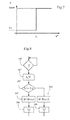
figure 7 , une troisième variante d'une loi de comportement souhaitée de l'installation de lafigure 1 ; - la
figure 8 , un logigramme de mise en oeuvre de la loi de comportement de lafigure 7 .
- the
figure 1 , a schematic view of a home automation installation according to one aspect of the invention; - the
figure 2 , a detail view of a remote control of the installation of thefigure 1 ; - the
figure 3 , a first variant of a desired law of behavior of the installation of thefigure 1 ; - the
figure 4 , a logigram of implementation of the law of behavior of thefigure 3 ; - the
figure 5 , a second variant of a desired law of behavior of the installation of thefigure 1 ; - the
figure 6 , a logigram of implementation of the law of behavior of thefigure 5 ; - the
figure 7 , a third variant of a desired law of behavior of the installation of thefigure 1 ; - the
figure 8 , a logigram of implementation of the law of behavior of thefigure 7 .
Pour plus de clarté, les éléments identiques seront repérés par des signes de référence identiques sur l'ensemble des figures.For the sake of clarity, the identical elements will be marked by identical reference signs throughout the figures.
Sur la
La télécommande 18, illustrée sur la
On a représenté sur la
En pratique, on peut mettre en oeuvre cette loi de comportement souhaitée à l'aide d'un microprocesseur ou plus généralement du circuit électrique 36 intégré à la télécommande 18 de la manière suivante, illustrée sur la
On compare à l'issue de l'étape 102 la valeur d'amplitude détectée A à un seuil prédéterminé AS (étape 104), par exemple un seuil de 6 incréments, pour en déduire si l'on doit interpréter le déplacement de la molette 20 comme un déplacement de précision ou un déplacement rapide. Si l'amplitude A est inférieure au seuil d'amplitude AS, le déplacement est interprété comme un déplacement de précision (étape 106), et l'on fait correspondre à chaque incrément angulaire de la molette un pas de rotation unitaire de l'actionneur, de sorte que la télécommande envoie à l'actionneur à l'étape 108 un ordre de progresser d'un nombre A de pas correspond à la valeur détectée de l'amplitude A de la rotation de la molette (RS=1). Si l'amplitude A de la rotation est supérieure au seuil AS, le déplacement est interprété à l'étape 110 comme remplissant les conditions de pilotage long. La télécommande peut alors envoyer un ordre de déplacement vers la position de fin de course correspondante. Ceci peut être réalisé par l'action suivante : la télécommande envoie alors à l'étape 112 une consigne de déplacement BMAX d'amplitude supérieure à l'amplitude maximale de déplacement de l'actionneur, de sorte que celui-ci atteint sa position de fin de course où il s'arrête de lui-même.At the end of
On a représenté sur la
Pour mettre en oeuvre cette loi de comportement, on peut procéder comme illustré sur la
On peut également envisager une loi de comportement fonction d'une vitesse détectée V de déplacement du doigt de l'utilisateur. Un exemple d'une telle loi est illustré sur la
Pour mettre en oeuvre cette loi de comportement, on peut procéder comme illustré sur la
Naturellement, diverses variantes sont envisageables. On peut notamment prévoir une loi qui soit une fonction en escalier avec plusieurs valeurs seuils de la vitesse ou de l'amplitude.Naturally, various variants are conceivable. In particular, it is possible to provide a law that is a step function with several threshold values of speed or amplitude.
Les incréments de déplacement de l'actionneur peuvent être définis par tout moyen, par exemple en définissant une durée unitaire d'alimentation électrique de l'actionneur ou un angle unitaire de rotation.The displacement increments of the actuator can be defined by any means, for example by defining a unitary power supply duration of the actuator or a unit angle of rotation.
Le circuit électrique interprétant les signaux des capteurs 28.1, 28.2 peut être au moins partiellement situé au niveau de l'actionneur.The electrical circuit interpreting the signals of the sensors 28.1, 28.2 may be at least partially located at the actuator.
On peut également envisager que la vitesse de déplacement de l'actionneur soit fonction de la vitesse de la molette, de sorte que les mouvements de grande amplitude soient effectués à plus grande vitesse que les mouvements de faible amplitude.It is also conceivable that the speed of movement of the actuator is a function of the speed of the wheel, so that the large amplitude movements are performed at a higher speed than the low amplitude movements.
Par analogie, le même type de commande peut être appliqué à une installation domotique dont les équipements comportent des éclairages à intensité variable.By analogy, the same type of control can be applied to a home automation system whose equipment includes dimmable lighting.
Claims (16)
Applications Claiming Priority (1)
| Application Number | Priority Date | Filing Date | Title |
|---|---|---|---|
| FR1262727A FR3000128B1 (en) | 2012-12-21 | 2012-12-21 | METHOD FOR CONTROLLING A SHUTTER AND ASSOCIATED INSTALLATION |
Publications (2)
| Publication Number | Publication Date |
|---|---|
| EP2747048A1 true EP2747048A1 (en) | 2014-06-25 |
| EP2747048B1 EP2747048B1 (en) | 2015-08-19 |
Family
ID=47902241
Family Applications (1)
| Application Number | Title | Priority Date | Filing Date |
|---|---|---|---|
| EP13197709.2A Active EP2747048B1 (en) | 2012-12-21 | 2013-12-17 | Method for controlling a flap and associated installation |
Country Status (2)
| Country | Link |
|---|---|
| EP (1) | EP2747048B1 (en) |
| FR (1) | FR3000128B1 (en) |
Citations (2)
| Publication number | Priority date | Publication date | Assignee | Title |
|---|---|---|---|---|
| EP1486640A1 (en) | 2003-06-10 | 2004-12-15 | Somfy SAS | Blind with adjustable slats |
| FR2858491A1 (en) * | 2003-07-29 | 2005-02-04 | Somfy | METHOD FOR CONTROLLING A MOTORIZED SCREEN AND DEVICE FOR CARRYING OUT SAID METHOD |
-
2012
- 2012-12-21 FR FR1262727A patent/FR3000128B1/en not_active Expired - Fee Related
-
2013
- 2013-12-17 EP EP13197709.2A patent/EP2747048B1/en active Active
Patent Citations (2)
| Publication number | Priority date | Publication date | Assignee | Title |
|---|---|---|---|---|
| EP1486640A1 (en) | 2003-06-10 | 2004-12-15 | Somfy SAS | Blind with adjustable slats |
| FR2858491A1 (en) * | 2003-07-29 | 2005-02-04 | Somfy | METHOD FOR CONTROLLING A MOTORIZED SCREEN AND DEVICE FOR CARRYING OUT SAID METHOD |
Also Published As
| Publication number | Publication date |
|---|---|
| FR3000128B1 (en) | 2015-06-05 |
| FR3000128A1 (en) | 2014-06-27 |
| EP2747048B1 (en) | 2015-08-19 |
Similar Documents
| Publication | Publication Date | Title |
|---|---|---|
| FR2944116A1 (en) | DEVICE FOR CONTROLLING THE DISPLACEMENT OF AN ELEMENT ACCORDING TO TWO OPPOSED Senses. | |
| EP2492884B1 (en) | Control device including an interface capable of proposing the next control order to be sent to a home-automation apparatus | |
| EP1486640B1 (en) | Blind with adjustable slats | |
| EP1508844A1 (en) | Method for initialising a motorized roller shutter | |
| EP2747048B1 (en) | Method for controlling a flap and associated installation | |
| EP2161818B1 (en) | Actuator for home-automation screen, tool and method for configuring such an actuator | |
| WO2015092168A1 (en) | Control device for a motor vehicle and control method | |
| FR2762334A3 (en) | Needle position registering system for circular knitting machines | |
| EP3205810B2 (en) | Apparatus for remote control of devices for closing a rack such as a leaf or roller shutter | |
| EP2819111B1 (en) | Home automation system controlled by programmable mobile remote control and programming method | |
| EP1111485A1 (en) | Device for controlling an apparatus able to go to a selected level among a range of levels, method for controlling a roller shutter with such a device, user unit for such a device | |
| EP2236450A1 (en) | Lifting device having a motion sensor | |
| FR2978789A1 (en) | METHOD FOR LEARNING A PARTICULAR POSITION OF AN ELECTRIC ACTUATOR FOR MANEUVERING DOMOTIC EQUIPMENT | |
| EP2109086B1 (en) | Stand-alone command transmitter for home-automation installation. | |
| EP1649126B1 (en) | Power-operated screen control method and device therefor | |
| EP2859306B1 (en) | Procedure of commanding an installation equipped with a rotary actuator and device of commanding associated thereto | |
| FR2998084A1 (en) | Method for controlling home automation installation, involves providing sequence with state change from initial state followed by return to initial state when actual manipulation corresponds to selection manipulation of equipments | |
| FR2972409A1 (en) | METHOD AND DEVICE FOR CONTROLLING AN ELECTRIC WIPER MOTOR | |
| EP1971902A1 (en) | Learning method of a control unit for the electrical supply of a motor | |
| FR3047765A1 (en) | APPARATUS FOR REMOTELY CONTROLLING ROLLER OR SWING SHUTTER TYPE BAY CLOSURE DEVICES. | |
| FR2934080A1 (en) | Haptic feedback i.e. vibration, control device for e.g. touch screen, has processing unit modulating control parameter so that result of vibration effect is felt along directions similar and opposite to finger displacement direction | |
| FR3035234A1 (en) | METHOD FOR CONTROLLING THE OPERATION OF A DOMOTIC CLOSURE OR SOLAR PROTECTION INSTALLATION AND ASSOCIATED DOMOTIC INSTALLATION | |
| FR2888688A1 (en) | Sensor-transmitter/solar protection device communication method, for building, involves determining predefined transmitting threshold according to intensity of phenomenon, where threshold values are recorded in memory of sensor-transmitter | |
| EP2337051A1 (en) | Home automation system control device consisting of a remote control housing equipped with a movable thumbwheel rotating around a spindle | |
| WO2007135289A2 (en) | Remote control device |
Legal Events
| Date | Code | Title | Description |
|---|---|---|---|
| PUAI | Public reference made under article 153(3) epc to a published international application that has entered the european phase |
Free format text: ORIGINAL CODE: 0009012 |
|
| 17P | Request for examination filed |
Effective date: 20131217 |
|
| AK | Designated contracting states |
Kind code of ref document: A1 Designated state(s): AL AT BE BG CH CY CZ DE DK EE ES FI FR GB GR HR HU IE IS IT LI LT LU LV MC MK MT NL NO PL PT RO RS SE SI SK SM TR |
|
| AX | Request for extension of the european patent |
Extension state: BA ME |
|
| R17P | Request for examination filed (corrected) |
Effective date: 20141202 |
|
| RBV | Designated contracting states (corrected) |
Designated state(s): AL AT BE BG CH CY CZ DE DK EE ES FI FR GB GR HR HU IE IS IT LI LT LU LV MC MK MT NL NO PL PT RO RS SE SI SK SM TR |
|
| RIN1 | Information on inventor provided before grant (corrected) |
Inventor name: MUGNIER, MICKAEL Inventor name: COSSON, JACQUES Inventor name: DEVIS, FREDERIC Inventor name: VALLEIX, DAVID |
|
| GRAP | Despatch of communication of intention to grant a patent |
Free format text: ORIGINAL CODE: EPIDOSNIGR1 |
|
| INTG | Intention to grant announced |
Effective date: 20150203 |
|
| GRAS | Grant fee paid |
Free format text: ORIGINAL CODE: EPIDOSNIGR3 |
|
| GRAA | (expected) grant |
Free format text: ORIGINAL CODE: 0009210 |
|
| AK | Designated contracting states |
Kind code of ref document: B1 Designated state(s): AL AT BE BG CH CY CZ DE DK EE ES FI FR GB GR HR HU IE IS IT LI LT LU LV MC MK MT NL NO PL PT RO RS SE SI SK SM TR |
|
| REG | Reference to a national code |
Ref country code: GB Ref legal event code: FG4D Free format text: NOT ENGLISH |
|
| REG | Reference to a national code |
Ref country code: CH Ref legal event code: EP |
|
| REG | Reference to a national code |
Ref country code: IE Ref legal event code: FG4D Free format text: LANGUAGE OF EP DOCUMENT: FRENCH |
|
| REG | Reference to a national code |
Ref country code: AT Ref legal event code: REF Ref document number: 744284 Country of ref document: AT Kind code of ref document: T Effective date: 20150915 |
|
| REG | Reference to a national code |
Ref country code: DE Ref legal event code: R096 Ref document number: 602013002736 Country of ref document: DE |
|
| REG | Reference to a national code |
Ref country code: FR Ref legal event code: PLFP Year of fee payment: 3 |
|
| REG | Reference to a national code |
Ref country code: CH Ref legal event code: NV Representative=s name: BUGNION S.A., CH |
|
| REG | Reference to a national code |
Ref country code: AT Ref legal event code: MK05 Ref document number: 744284 Country of ref document: AT Kind code of ref document: T Effective date: 20150819 |
|
| REG | Reference to a national code |
Ref country code: LT Ref legal event code: MG4D |
|
| REG | Reference to a national code |
Ref country code: NL Ref legal event code: MP Effective date: 20150819 |
|
| PG25 | Lapsed in a contracting state [announced via postgrant information from national office to epo] |
Ref country code: LV Free format text: LAPSE BECAUSE OF FAILURE TO SUBMIT A TRANSLATION OF THE DESCRIPTION OR TO PAY THE FEE WITHIN THE PRESCRIBED TIME-LIMIT Effective date: 20150819 Ref country code: NO Free format text: LAPSE BECAUSE OF FAILURE TO SUBMIT A TRANSLATION OF THE DESCRIPTION OR TO PAY THE FEE WITHIN THE PRESCRIBED TIME-LIMIT Effective date: 20151119 Ref country code: GR Free format text: LAPSE BECAUSE OF FAILURE TO SUBMIT A TRANSLATION OF THE DESCRIPTION OR TO PAY THE FEE WITHIN THE PRESCRIBED TIME-LIMIT Effective date: 20151120 Ref country code: FI Free format text: LAPSE BECAUSE OF FAILURE TO SUBMIT A TRANSLATION OF THE DESCRIPTION OR TO PAY THE FEE WITHIN THE PRESCRIBED TIME-LIMIT Effective date: 20150819 Ref country code: LT Free format text: LAPSE BECAUSE OF FAILURE TO SUBMIT A TRANSLATION OF THE DESCRIPTION OR TO PAY THE FEE WITHIN THE PRESCRIBED TIME-LIMIT Effective date: 20150819 |
|
| PG25 | Lapsed in a contracting state [announced via postgrant information from national office to epo] |
Ref country code: PT Free format text: LAPSE BECAUSE OF FAILURE TO SUBMIT A TRANSLATION OF THE DESCRIPTION OR TO PAY THE FEE WITHIN THE PRESCRIBED TIME-LIMIT Effective date: 20151221 Ref country code: RS Free format text: LAPSE BECAUSE OF FAILURE TO SUBMIT A TRANSLATION OF THE DESCRIPTION OR TO PAY THE FEE WITHIN THE PRESCRIBED TIME-LIMIT Effective date: 20150819 Ref country code: SE Free format text: LAPSE BECAUSE OF FAILURE TO SUBMIT A TRANSLATION OF THE DESCRIPTION OR TO PAY THE FEE WITHIN THE PRESCRIBED TIME-LIMIT Effective date: 20150819 Ref country code: IS Free format text: LAPSE BECAUSE OF FAILURE TO SUBMIT A TRANSLATION OF THE DESCRIPTION OR TO PAY THE FEE WITHIN THE PRESCRIBED TIME-LIMIT Effective date: 20151219 Ref country code: ES Free format text: LAPSE BECAUSE OF FAILURE TO SUBMIT A TRANSLATION OF THE DESCRIPTION OR TO PAY THE FEE WITHIN THE PRESCRIBED TIME-LIMIT Effective date: 20150819 Ref country code: AT Free format text: LAPSE BECAUSE OF FAILURE TO SUBMIT A TRANSLATION OF THE DESCRIPTION OR TO PAY THE FEE WITHIN THE PRESCRIBED TIME-LIMIT Effective date: 20150819 Ref country code: PL Free format text: LAPSE BECAUSE OF FAILURE TO SUBMIT A TRANSLATION OF THE DESCRIPTION OR TO PAY THE FEE WITHIN THE PRESCRIBED TIME-LIMIT Effective date: 20150819 |
|
| PG25 | Lapsed in a contracting state [announced via postgrant information from national office to epo] |
Ref country code: NL Free format text: LAPSE BECAUSE OF FAILURE TO SUBMIT A TRANSLATION OF THE DESCRIPTION OR TO PAY THE FEE WITHIN THE PRESCRIBED TIME-LIMIT Effective date: 20150819 |
|
| PG25 | Lapsed in a contracting state [announced via postgrant information from national office to epo] |
Ref country code: SK Free format text: LAPSE BECAUSE OF FAILURE TO SUBMIT A TRANSLATION OF THE DESCRIPTION OR TO PAY THE FEE WITHIN THE PRESCRIBED TIME-LIMIT Effective date: 20150819 Ref country code: IT Free format text: LAPSE BECAUSE OF FAILURE TO SUBMIT A TRANSLATION OF THE DESCRIPTION OR TO PAY THE FEE WITHIN THE PRESCRIBED TIME-LIMIT Effective date: 20150819 Ref country code: EE Free format text: LAPSE BECAUSE OF FAILURE TO SUBMIT A TRANSLATION OF THE DESCRIPTION OR TO PAY THE FEE WITHIN THE PRESCRIBED TIME-LIMIT Effective date: 20150819 Ref country code: DK Free format text: LAPSE BECAUSE OF FAILURE TO SUBMIT A TRANSLATION OF THE DESCRIPTION OR TO PAY THE FEE WITHIN THE PRESCRIBED TIME-LIMIT Effective date: 20150819 Ref country code: CZ Free format text: LAPSE BECAUSE OF FAILURE TO SUBMIT A TRANSLATION OF THE DESCRIPTION OR TO PAY THE FEE WITHIN THE PRESCRIBED TIME-LIMIT Effective date: 20150819 |
|
| REG | Reference to a national code |
Ref country code: DE Ref legal event code: R097 Ref document number: 602013002736 Country of ref document: DE |
|
| PG25 | Lapsed in a contracting state [announced via postgrant information from national office to epo] |
Ref country code: BE Free format text: LAPSE BECAUSE OF NON-PAYMENT OF DUE FEES Effective date: 20151231 Ref country code: RO Free format text: LAPSE BECAUSE OF FAILURE TO SUBMIT A TRANSLATION OF THE DESCRIPTION OR TO PAY THE FEE WITHIN THE PRESCRIBED TIME-LIMIT Effective date: 20150819 |
|
| PLBE | No opposition filed within time limit |
Free format text: ORIGINAL CODE: 0009261 |
|
| STAA | Information on the status of an ep patent application or granted ep patent |
Free format text: STATUS: NO OPPOSITION FILED WITHIN TIME LIMIT |
|
| 26N | No opposition filed |
Effective date: 20160520 |
|
| PG25 | Lapsed in a contracting state [announced via postgrant information from national office to epo] |
Ref country code: MC Free format text: LAPSE BECAUSE OF FAILURE TO SUBMIT A TRANSLATION OF THE DESCRIPTION OR TO PAY THE FEE WITHIN THE PRESCRIBED TIME-LIMIT Effective date: 20150819 Ref country code: LU Free format text: LAPSE BECAUSE OF FAILURE TO SUBMIT A TRANSLATION OF THE DESCRIPTION OR TO PAY THE FEE WITHIN THE PRESCRIBED TIME-LIMIT Effective date: 20151217 |
|
| REG | Reference to a national code |
Ref country code: DE Ref legal event code: R082 Ref document number: 602013002736 Country of ref document: DE |
|
| PG25 | Lapsed in a contracting state [announced via postgrant information from national office to epo] |
Ref country code: SI Free format text: LAPSE BECAUSE OF FAILURE TO SUBMIT A TRANSLATION OF THE DESCRIPTION OR TO PAY THE FEE WITHIN THE PRESCRIBED TIME-LIMIT Effective date: 20150819 |
|
| REG | Reference to a national code |
Ref country code: IE Ref legal event code: MM4A |
|
| PG25 | Lapsed in a contracting state [announced via postgrant information from national office to epo] |
Ref country code: IE Free format text: LAPSE BECAUSE OF NON-PAYMENT OF DUE FEES Effective date: 20151217 |
|
| REG | Reference to a national code |
Ref country code: FR Ref legal event code: PLFP Year of fee payment: 4 |
|
| PG25 | Lapsed in a contracting state [announced via postgrant information from national office to epo] |
Ref country code: HU Free format text: LAPSE BECAUSE OF FAILURE TO SUBMIT A TRANSLATION OF THE DESCRIPTION OR TO PAY THE FEE WITHIN THE PRESCRIBED TIME-LIMIT; INVALID AB INITIO Effective date: 20131217 Ref country code: BG Free format text: LAPSE BECAUSE OF FAILURE TO SUBMIT A TRANSLATION OF THE DESCRIPTION OR TO PAY THE FEE WITHIN THE PRESCRIBED TIME-LIMIT Effective date: 20150819 |
|
| PG25 | Lapsed in a contracting state [announced via postgrant information from national office to epo] |
Ref country code: CY Free format text: LAPSE BECAUSE OF FAILURE TO SUBMIT A TRANSLATION OF THE DESCRIPTION OR TO PAY THE FEE WITHIN THE PRESCRIBED TIME-LIMIT Effective date: 20150819 |
|
| PG25 | Lapsed in a contracting state [announced via postgrant information from national office to epo] |
Ref country code: HR Free format text: LAPSE BECAUSE OF FAILURE TO SUBMIT A TRANSLATION OF THE DESCRIPTION OR TO PAY THE FEE WITHIN THE PRESCRIBED TIME-LIMIT Effective date: 20150819 |
|
| PG25 | Lapsed in a contracting state [announced via postgrant information from national office to epo] |
Ref country code: MT Free format text: LAPSE BECAUSE OF FAILURE TO SUBMIT A TRANSLATION OF THE DESCRIPTION OR TO PAY THE FEE WITHIN THE PRESCRIBED TIME-LIMIT Effective date: 20150819 |
|
| REG | Reference to a national code |
Ref country code: FR Ref legal event code: PLFP Year of fee payment: 5 |
|
| PG25 | Lapsed in a contracting state [announced via postgrant information from national office to epo] |
Ref country code: SM Free format text: LAPSE BECAUSE OF FAILURE TO SUBMIT A TRANSLATION OF THE DESCRIPTION OR TO PAY THE FEE WITHIN THE PRESCRIBED TIME-LIMIT Effective date: 20150819 |
|
| PG25 | Lapsed in a contracting state [announced via postgrant information from national office to epo] |
Ref country code: MK Free format text: LAPSE BECAUSE OF FAILURE TO SUBMIT A TRANSLATION OF THE DESCRIPTION OR TO PAY THE FEE WITHIN THE PRESCRIBED TIME-LIMIT Effective date: 20150819 |
|
| GBPC | Gb: european patent ceased through non-payment of renewal fee |
Effective date: 20171217 |
|
| PG25 | Lapsed in a contracting state [announced via postgrant information from national office to epo] |
Ref country code: TR Free format text: LAPSE BECAUSE OF FAILURE TO SUBMIT A TRANSLATION OF THE DESCRIPTION OR TO PAY THE FEE WITHIN THE PRESCRIBED TIME-LIMIT Effective date: 20150819 Ref country code: AL Free format text: LAPSE BECAUSE OF FAILURE TO SUBMIT A TRANSLATION OF THE DESCRIPTION OR TO PAY THE FEE WITHIN THE PRESCRIBED TIME-LIMIT Effective date: 20150819 |
|
| PG25 | Lapsed in a contracting state [announced via postgrant information from national office to epo] |
Ref country code: GB Free format text: LAPSE BECAUSE OF NON-PAYMENT OF DUE FEES Effective date: 20171217 |
|
| REG | Reference to a national code |
Ref country code: DE Ref legal event code: R081 Ref document number: 602013002736 Country of ref document: DE Owner name: SOMFY ACTIVITES SA, FR Free format text: FORMER OWNER: SOMFY SAS, CLUSES, FR |
|
| PGFP | Annual fee paid to national office [announced via postgrant information from national office to epo] |
Ref country code: CH Payment date: 20230101 Year of fee payment: 10 |
|
| PGFP | Annual fee paid to national office [announced via postgrant information from national office to epo] |
Ref country code: FR Payment date: 20231106 Year of fee payment: 11 Ref country code: DE Payment date: 20231124 Year of fee payment: 11 |