EP2057760B1 - Transform-domain feedback signaling for mimo communication - Google Patents
Transform-domain feedback signaling for mimo communication Download PDFInfo
- Publication number
- EP2057760B1 EP2057760B1 EP07826049.4A EP07826049A EP2057760B1 EP 2057760 B1 EP2057760 B1 EP 2057760B1 EP 07826049 A EP07826049 A EP 07826049A EP 2057760 B1 EP2057760 B1 EP 2057760B1
- Authority
- EP
- European Patent Office
- Prior art keywords
- channel
- transmitter
- receiver
- coefficients
- array
- Prior art date
- Legal status (The legal status is an assumption and is not a legal conclusion. Google has not performed a legal analysis and makes no representation as to the accuracy of the status listed.)
- Active
Links
- 238000004891 communication Methods 0.000 title claims description 45
- 230000011664 signaling Effects 0.000 title claims description 28
- 238000000034 method Methods 0.000 claims description 91
- 238000005259 measurement Methods 0.000 claims description 51
- 239000013598 vector Substances 0.000 claims description 39
- 230000005540 biological transmission Effects 0.000 claims description 30
- 230000002441 reversible effect Effects 0.000 claims description 16
- 238000004590 computer program Methods 0.000 claims description 10
- 238000000354 decomposition reaction Methods 0.000 claims description 10
- 238000013139 quantization Methods 0.000 description 21
- 238000010586 diagram Methods 0.000 description 11
- 239000011159 matrix material Substances 0.000 description 10
- 230000004044 response Effects 0.000 description 10
- 238000005516 engineering process Methods 0.000 description 8
- 238000013461 design Methods 0.000 description 7
- 230000008901 benefit Effects 0.000 description 5
- 230000006870 function Effects 0.000 description 4
- 230000008569 process Effects 0.000 description 3
- 230000009466 transformation Effects 0.000 description 3
- 238000003491 array Methods 0.000 description 2
- 238000004364 calculation method Methods 0.000 description 2
- 230000010267 cellular communication Effects 0.000 description 2
- 230000001413 cellular effect Effects 0.000 description 2
- 230000007423 decrease Effects 0.000 description 2
- 230000001419 dependent effect Effects 0.000 description 2
- 238000005562 fading Methods 0.000 description 2
- 238000010295 mobile communication Methods 0.000 description 2
- 230000005855 radiation Effects 0.000 description 2
- 230000003595 spectral effect Effects 0.000 description 2
- 239000000654 additive Substances 0.000 description 1
- 230000000996 additive effect Effects 0.000 description 1
- 238000012938 design process Methods 0.000 description 1
- 230000000694 effects Effects 0.000 description 1
- 238000011156 evaluation Methods 0.000 description 1
- 238000009499 grossing Methods 0.000 description 1
- 230000002452 interceptive effect Effects 0.000 description 1
- 230000007774 longterm Effects 0.000 description 1
- 230000003287 optical effect Effects 0.000 description 1
- 238000013468 resource allocation Methods 0.000 description 1
- 238000000926 separation method Methods 0.000 description 1
- 238000004088 simulation Methods 0.000 description 1
- 238000000844 transformation Methods 0.000 description 1
- 239000002699 waste material Substances 0.000 description 1
Images


Classifications
-
- H—ELECTRICITY
- H04—ELECTRIC COMMUNICATION TECHNIQUE
- H04B—TRANSMISSION
- H04B7/00—Radio transmission systems, i.e. using radiation field
- H04B7/02—Diversity systems; Multi-antenna system, i.e. transmission or reception using multiple antennas
- H04B7/04—Diversity systems; Multi-antenna system, i.e. transmission or reception using multiple antennas using two or more spaced independent antennas
- H04B7/06—Diversity systems; Multi-antenna system, i.e. transmission or reception using multiple antennas using two or more spaced independent antennas at the transmitting station
- H04B7/0613—Diversity systems; Multi-antenna system, i.e. transmission or reception using multiple antennas using two or more spaced independent antennas at the transmitting station using simultaneous transmission
- H04B7/0615—Diversity systems; Multi-antenna system, i.e. transmission or reception using multiple antennas using two or more spaced independent antennas at the transmitting station using simultaneous transmission of weighted versions of same signal
- H04B7/0619—Diversity systems; Multi-antenna system, i.e. transmission or reception using multiple antennas using two or more spaced independent antennas at the transmitting station using simultaneous transmission of weighted versions of same signal using feedback from receiving side
- H04B7/0621—Feedback content
- H04B7/0632—Channel quality parameters, e.g. channel quality indicator [CQI]
-
- H—ELECTRICITY
- H04—ELECTRIC COMMUNICATION TECHNIQUE
- H04B—TRANSMISSION
- H04B7/00—Radio transmission systems, i.e. using radiation field
- H04B7/02—Diversity systems; Multi-antenna system, i.e. transmission or reception using multiple antennas
- H04B7/04—Diversity systems; Multi-antenna system, i.e. transmission or reception using multiple antennas using two or more spaced independent antennas
- H04B7/0413—MIMO systems
- H04B7/0417—Feedback systems
-
- H—ELECTRICITY
- H04—ELECTRIC COMMUNICATION TECHNIQUE
- H04B—TRANSMISSION
- H04B7/00—Radio transmission systems, i.e. using radiation field
- H04B7/02—Diversity systems; Multi-antenna system, i.e. transmission or reception using multiple antennas
- H04B7/04—Diversity systems; Multi-antenna system, i.e. transmission or reception using multiple antennas using two or more spaced independent antennas
- H04B7/06—Diversity systems; Multi-antenna system, i.e. transmission or reception using multiple antennas using two or more spaced independent antennas at the transmitting station
- H04B7/0613—Diversity systems; Multi-antenna system, i.e. transmission or reception using multiple antennas using two or more spaced independent antennas at the transmitting station using simultaneous transmission
- H04B7/0615—Diversity systems; Multi-antenna system, i.e. transmission or reception using multiple antennas using two or more spaced independent antennas at the transmitting station using simultaneous transmission of weighted versions of same signal
- H04B7/0617—Diversity systems; Multi-antenna system, i.e. transmission or reception using multiple antennas using two or more spaced independent antennas at the transmitting station using simultaneous transmission of weighted versions of same signal for beam forming
-
- H—ELECTRICITY
- H04—ELECTRIC COMMUNICATION TECHNIQUE
- H04B—TRANSMISSION
- H04B7/00—Radio transmission systems, i.e. using radiation field
- H04B7/02—Diversity systems; Multi-antenna system, i.e. transmission or reception using multiple antennas
- H04B7/04—Diversity systems; Multi-antenna system, i.e. transmission or reception using multiple antennas using two or more spaced independent antennas
- H04B7/06—Diversity systems; Multi-antenna system, i.e. transmission or reception using multiple antennas using two or more spaced independent antennas at the transmitting station
- H04B7/0613—Diversity systems; Multi-antenna system, i.e. transmission or reception using multiple antennas using two or more spaced independent antennas at the transmitting station using simultaneous transmission
- H04B7/0615—Diversity systems; Multi-antenna system, i.e. transmission or reception using multiple antennas using two or more spaced independent antennas at the transmitting station using simultaneous transmission of weighted versions of same signal
- H04B7/0619—Diversity systems; Multi-antenna system, i.e. transmission or reception using multiple antennas using two or more spaced independent antennas at the transmitting station using simultaneous transmission of weighted versions of same signal using feedback from receiving side
- H04B7/0621—Feedback content
- H04B7/0626—Channel coefficients, e.g. channel state information [CSI]
-
- H—ELECTRICITY
- H04—ELECTRIC COMMUNICATION TECHNIQUE
- H04B—TRANSMISSION
- H04B7/00—Radio transmission systems, i.e. using radiation field
- H04B7/02—Diversity systems; Multi-antenna system, i.e. transmission or reception using multiple antennas
- H04B7/04—Diversity systems; Multi-antenna system, i.e. transmission or reception using multiple antennas using two or more spaced independent antennas
- H04B7/06—Diversity systems; Multi-antenna system, i.e. transmission or reception using multiple antennas using two or more spaced independent antennas at the transmitting station
- H04B7/0613—Diversity systems; Multi-antenna system, i.e. transmission or reception using multiple antennas using two or more spaced independent antennas at the transmitting station using simultaneous transmission
- H04B7/0615—Diversity systems; Multi-antenna system, i.e. transmission or reception using multiple antennas using two or more spaced independent antennas at the transmitting station using simultaneous transmission of weighted versions of same signal
- H04B7/0619—Diversity systems; Multi-antenna system, i.e. transmission or reception using multiple antennas using two or more spaced independent antennas at the transmitting station using simultaneous transmission of weighted versions of same signal using feedback from receiving side
- H04B7/0621—Feedback content
- H04B7/0634—Antenna weights or vector/matrix coefficients
-
- H—ELECTRICITY
- H04—ELECTRIC COMMUNICATION TECHNIQUE
- H04B—TRANSMISSION
- H04B7/00—Radio transmission systems, i.e. using radiation field
- H04B7/02—Diversity systems; Multi-antenna system, i.e. transmission or reception using multiple antennas
- H04B7/04—Diversity systems; Multi-antenna system, i.e. transmission or reception using multiple antennas using two or more spaced independent antennas
- H04B7/06—Diversity systems; Multi-antenna system, i.e. transmission or reception using multiple antennas using two or more spaced independent antennas at the transmitting station
- H04B7/0613—Diversity systems; Multi-antenna system, i.e. transmission or reception using multiple antennas using two or more spaced independent antennas at the transmitting station using simultaneous transmission
- H04B7/0615—Diversity systems; Multi-antenna system, i.e. transmission or reception using multiple antennas using two or more spaced independent antennas at the transmitting station using simultaneous transmission of weighted versions of same signal
- H04B7/0619—Diversity systems; Multi-antenna system, i.e. transmission or reception using multiple antennas using two or more spaced independent antennas at the transmitting station using simultaneous transmission of weighted versions of same signal using feedback from receiving side
- H04B7/0636—Feedback format
- H04B7/0639—Using selective indices, e.g. of a codebook, e.g. pre-distortion matrix index [PMI] or for beam selection
-
- H—ELECTRICITY
- H04—ELECTRIC COMMUNICATION TECHNIQUE
- H04L—TRANSMISSION OF DIGITAL INFORMATION, e.g. TELEGRAPHIC COMMUNICATION
- H04L25/00—Baseband systems
- H04L25/02—Details ; arrangements for supplying electrical power along data transmission lines
- H04L25/0202—Channel estimation
- H04L25/0224—Channel estimation using sounding signals
-
- H—ELECTRICITY
- H04—ELECTRIC COMMUNICATION TECHNIQUE
- H04B—TRANSMISSION
- H04B17/00—Monitoring; Testing
- H04B17/30—Monitoring; Testing of propagation channels
- H04B17/309—Measuring or estimating channel quality parameters
- H04B17/336—Signal-to-interference ratio [SIR] or carrier-to-interference ratio [CIR]
-
- H—ELECTRICITY
- H04—ELECTRIC COMMUNICATION TECHNIQUE
- H04B—TRANSMISSION
- H04B7/00—Radio transmission systems, i.e. using radiation field
- H04B7/02—Diversity systems; Multi-antenna system, i.e. transmission or reception using multiple antennas
- H04B7/04—Diversity systems; Multi-antenna system, i.e. transmission or reception using multiple antennas using two or more spaced independent antennas
- H04B7/0413—MIMO systems
Definitions
- the present invention relates to:
- MIMO Multiple-input multiple-output
- WLAN wireless local area networks
- a plurality of two or more transmit antennas is also referred to as an array of transmit antennas herein.
- MIMO communication is obtained through a combination of antenna arrays that provide spatial diversity from the propagation channel and algorithms that can adapt to the changing multivariate channel.
- UMTS LTE Universal Mobile Telecommunication System
- a significant gain in spectral efficiency can be achieved in a downlink transmission by multiplexing multiple codewords in the spatial domain to either a single user or multiple users sharing the same time-frequency resource block.
- SDM spatial division multiplexing
- SDMA spatial division multiple access
- An SDMA scheme enables multiple users within the same radio cell to be accommodated on the same frequency or time slot.
- the realization of this technique can be accomplished by using an antenna array, which is capable of modifying its time, frequency, and spatial response by means of the amplitude and phase weighting and an internal feedback control.
- Beamforming is a method used to create a radiation pattern of the antenna array by constructively adding the phases of the signals in the direction of the communication targets (terminal devices) desired, and nulling the pattern of the communication targets that are undesired or interfering.
- the beamforming vector plays an important role.
- H a N ⁇ M channel matrix connecting the transmitter and the receiver
- z the receive combining vector
- z H its Hermitian transpose
- w the transmit beamforming vector
- x the transmitted symbol from a chosen constellation
- n independent noise added at the receiver.
- the base station uses the feedback information from the users only to schedule transmission to the set of users reporting the best CQI values.
- the base station could implement an ad-hoc design of the beamformer. This is possible, for example, if the users report all the channel coefficients, after some quantization operation. However, this requires signaling as many complex values as the product, MN, between the number M of transmit antennas and the number N of receive antennas per user.
- US 20060094373 discloses a closed-loop signalling method which controls multiple transmit beams. The method also includes transmitting a plurality of beams from a first transceiver via a plurality of transmission channels to a second transceiver, evaluating, at the second transceiver, characteristics of the plurality of transmitted beams received at the second transceiver.
- 3GPP TSG-RAN WG1 #44 - R1-060457 describes single and multiple codeword schemes with precoding.
- WO 2006006770 discloses an apparatus and method for transmitting and receiving packet data using multiple antennas in a wireless communication system.
- the apparatus and method can efficiently transmit and receive packet data according to channel conditions without a waste of transmission bandwidth.
- a control method for a communication network that has a transmitter with an array of transmit antennas and that has at least one receiver communicating with the transmitter is provided.
- the method comprises the steps:
- the method of the invention allows an advantageous control of a beamforming process on the transmitter side, based on communicating channel component coefficients indicative of the individual weight of respective channel components in an angular domain from the receiver to the transmitter.
- the method overcomes a main issue with codebook-based solutions, namely, that beamforming vectors are not jointly optimized according to the channel conditions.
- the transmitter typically uses feedback information from the receivers, like wireless mobile terminal devices, only to schedule transmission to the set of users reporting the best CQI values.
- transmitter and receiver are chosen with reference to the role of the respective device in a communication.
- the transmitter of the claims can also take the role of a receiver in a different communication
- the receiver of the claims can also take the role of the transmitter in a different communication.
- Both devices can be transceiver devices that are configured to perform the method steps associated with the transmitter and configured to perform the method steps associated with the receiver.
- a preferred configuration for an application of the method of the invention is that of a base station forming the transmitter and a mobile terminal forming the receiver in a MIMO communication network.
- performing a channel measurement comprises measuring pilot information transmitted from each of the array of transmit antennas at the transmitter.
- the pilot signals are designed to be orthogonal between each antenna of the array of transmit antennas.
- the reversible transformation applied to the channel coefficients is linear and orthogonal; this helps reduce the computational complexity at the receiver.
- the transform comprises an Inverse Discrete Fourier Transform (IDFT).
- IDFT Inverse Discrete Fourier Transform
- the channel components in the angular domain indicate different angles or angular intervals.
- the channel-component coefficients in this embodiment can take the form of an ordered set of index values, indicating a magnitude associated with an angle or angular interval determined by the index order.
- the feedback information communicated from the receiver to the transmitter may comprise one or more preferred receiving directions determined from data in the angular domain.
- This feedback information may be quantized as an integer indexing an angular quantization grid.
- each receiver computes an L-point IDFT of ⁇ , and takes the absolute value, i.e. forms a vector ⁇ a with elements ⁇ a,l as given by equation (1).
- This vector ⁇ a represents a quantized version of the angular-domain response amplitude of the channel.
- IDFT is a suitable transform.
- Other transforms could be used that are a linear, reversible and orthogonal.
- a further embodiment comprises a step of determining a measure of uncertainty of the channel component coefficients in the angular domain at the receiver after applying the linear and reversible orthogonal transform to the channel coefficients. For example this could be determined from the transformed coefficients in the form of a beamwidth. As another example, this could be determined from the range of variation of sets of channel coefficients or channel component coefficients obtained at different times or at different frequencies.
- Another embodiment comprises a step of applying a filter to the channel component coefficients in the angular domain at the receiver.
- This embodiment forms one way of including the effects of uncertainty in the measured channel coefficients.
- use of a smoothing filter is equivalent to including angular uncertainty.
- selecting one or more channel components in the angular domain comprises ascertaining and selecting a channel component that has a channel component coefficient, which forms an either absolute or relative maximum of magnitude in the set of channel component coefficients.
- the embodiment forms a direction finding technique. Other direction finding techniques could be employed
- a further embodiment therefore comprises:
- phase information In the case of multiple peaks phase information would be included with the magnitudes in the communicating step.
- communicating the control signal to the transmitter comprises communicating via a radio link, wherein control information comprised by the control signal, as defined in alternatives A), 1) to 3), mentioned above, is preferably provided in quantized form.
- the possible quantized channel representations are stored in a codebook, which would allow more flexibility in the designing the channel quantizer to match the expected channel conditions.
- the codebook may be arranged such that the entries form unitary matrices.
- the selection of a preferred channel representation is made by finding the index of the codebook entry with the highest value of estimated SINR. This corresponds to identifying a preferred codebook index.
- a range of assumptions may be made about the interference from other transmissions, including the presence of transmissions on other beams and the precoding applied to these transmissions. Preferably these different assumptions would correspond to different decisions at the transmitter, for example to schedule transmissions to different users on different beams.
- the transmissions on other beams may use precoding selected from a codebook, which would have the advantage of limiting the number of possible beamformers, which would have to be implemented at the transmitter and the number of different possible beams, which would need to be taken into account at the receiver when considering assumptions about interference.
- the codebook index corresponding to the highest estimated SINR will in general depend on the assumed interference, different preferred codebook indices may be determined for different interference assumptions, In the case of a unitary codebook the indices may be constrained to be from the same unitary matrix (which limits the number of possibilities that need to be considered, leading to lower receiver complexity, but lower performance) or allowed to be from different unitary matrices (which is more flexible, but may lead to more signaling overhead to cover the additional possibilities).
- one or more of preferred codebook indices for different interference assumptions and some or all of the corresponding CQI values may be communicated to the transmitter.
- the set of assumptions to be considered at the receiver may be pre-determined, for example as a part of the system design, or configurable by signaling, since there will in general be a trade-off between increasing performance by considering a wider range of assumptions and the associated additional complexity and signaling overheads (e.g. from sending more indices and CQI values to the transmitter).
- the method of the first aspect of the invention can be extended by executing it once for each of the receive antennas. In one embodiment, therefore, the channel measurement is performed for each of an array of receive antennas at the receiver.
- the step of communicating to the transmitter comprises communicating a set of channel quality indicator (CQI) bits.
- CQI channel quality indicator
- constructing a beam pattern in the angular domain in one embodiment comprises constructing a transmit signal impulse in at least one of the one or more preferred channel components, where the preferred channel component can for instance form preferred angular directions.
- constructing a beam pattern in the angular domain preferably comprises constructing the transmit signal impulse with an amplitude determined according to the magnitude of the channel component coefficients.
- Another embodiment further comprises a step of determining a measure of uncertainty in the angular domain of the channel component coefficients at the transmitter after receiving the control signal. Determining a measure of uncertainty in the angular domain of the channel component coefficients at the transmitter can for example comprise evaluating a range of variation of the preferred channel components communicated at different times or at different frequencies.
- Another embodiment of the method of the first aspect of the invention comprises applying a filter to the beam pattern in the angular domain.
- this filter could be determined according to an obtained measure of uncertainty.
- Another embodiment comprises designing a beamformer for transmission from the transmitter to the receiver in dependence on the constructed beam pattern in the angular domain.
- Designing a beamformer can for instance comprise applying an inverse of the linear and reversible orthogonal transform, e.g., a Discrete Fourier Transform (DFT) that forms an inverse to the IDFT mentioned earlier, to the channel component coefficients.
- DFT Discrete Fourier Transform
- the beamformer design process could be based on coefficients received from more than one receiver.
- designing a beamformer is in another embodiment performed in additional dependence on channel component coefficients received from at least one second receiver different from the receiver.
- the beamformer is restricted to be one of a set of pre-coding coefficients from a pre-determined codebook. Limiting the flexibility of the pre-coding may lead to lower complexity at the transmitter, and may lead to less signaling overhead (e.g. if the codebook index is signaled to the receiver, rather than unrestricted values of pre-coding coefficients).
- the codebook may be constructed from unitary matrices.
- the codebooks may be different. This means that the contents and size of these codebooks can be independently designed to optimized the trade-off between such factors as system performance vs. complexity and signaling overhead.
- a channel can be assumed to be reciprocal (or approximately reciprocal) between uplink and downlink, so measurements may then be made in one direction and applied in the other. In this case the following steps would not be required:
- a vector quantizer can be applied to the channel measurements, instead of performing the steps:
- phase information is not required in many cases, may involve signaling a larger number of bits.
- a transmitting station selects a beamforming matrix based on feedback information from one or more receiving stations.
- the feedback information is derived from an Inverse Discrete Fourier Transform (IDFT) of a measure of channel characteristics made on a signal received at the receiving station.
- IDFT Inverse Discrete Fourier Transform
- the feedback information may comprise an indication of peak magnitude of signals in the angular domain.
- the feedback information may comprise an indication of angular uncertainty in the angular domain.
- a filter may be applied to the data in the angular domain.
- a control signaling method for a receiver in a communication network with a transmitter having an array of transmit antennas for transmission of user data to the receiver comprising:
- a third aspect of the invention is a computer program product, containing executable program code, which is configured to implement a control signaling method for a receiver in a communication network that has a transmitter having an array of transmit antennas for transmission of user data to the receiver, the control signaling method comprising the steps:
- the computer program product can be a receiver control software or a firmware stored on a data medium or implemented in a receiver, or an update software for a previous control software or firmware on a data medium.
- Embodiments of the computer program product of the third aspect of the invention contain executable program code, which is configured to implement a control signaling method for a receiver according to embodiments of the method of the first aspect of the invention which further specify method steps performed at the receiver.
- a receiver module for a communication network with a transmitter having an array of transmit antennas is provided.
- the receiver module comprises:
- the receiver module can form a component of a receiver or an independently traded add-on module to an existing receiver of a previous generation.
- the channel-measurement unit is configured to perform a channel measurement by measuring pilot information transmitted from each of the array of transmit antennas at the transmitter.
- the channel-measurement unit is further configured to determine a measure of uncertainty of the channel component coefficients in the angular domain.
- the channel-measurement unit is further configured to apply a filter to the channel component coefficients in the angular domain.
- control unit is configured to generate and provide at its output an uncertainty indicator that forms a measure of uncertainty of a channel component coefficient in the angular domain.
- the selection unit is in another embodiment configured to ascertain and select a channel component that has a channel component coefficient, which forms an either absolute or relative maximum of magnitude in the component coefficients received from the transform unit.
- the selection unit is configured to:
- the control unit is in one embodiment configured to communicate to the transmitter in quantized form one or more preferred channel components or a magnitude of one or more channel component coefficients via a radio link.
- the channel-measurement unit is configured to:
- control unit is preferably configured to communicate to the transmitter the control signal form in the form of a set of channel quality indicator bits.
- a receiver for a communication network with a transmitter having an array of transmit antennas comprising:
- the receiver comprises in one embodiment an array of receive antennas.
- the receiver forms a mobile terminal device for wireless communication.
- the receiver also comprises a transmitter according a seventh aspect of the invention or one of its embodiments, which will be described below.
- a transmitter control module which is configured:
- the transmitter control module can form a component of a transmitter or an independently traded add-on module to an existing receiver of a previous generation.
- the transmitter control module is further configured to:
- transmitter control module further comprises a channel-evaluation unit, which is configured to generate and provide at its output an uncertainty indicator forming a measure of uncertainty of the channel component coefficients in the angular domain.
- a transmitter comprising:
- the transmitter forms a base station in a mobile-communication network.
- the transmitter also comprises a receiver according to the fifth aspect of the invention or one of its embodiments.
- a transmitter control method comprising the steps:
- Embodiments of the transmitter control method correspond to those embodiments described in the context of the description of embodiments of the method of the first aspect of the invention, which further specify method steps performed at the transmitter.
- a computer program product containing executable program code, which is configured to implement a transmitter control method for a transmitter having an array of transmit antennas for transmission of user data to the receiver, the transmitter control method comprising the steps:
- Embodiments of the computer program product of the ninth aspect of the invention contain executable program code, which is configured to implement a transmitter control method corresponding to those embodiments described in the context of the description of embodiments of the method of the first aspect of the invention, which further specify method steps performed at the transmitter.
- the computer program product can be a transmitter control software or a firmware stored on a data medium or implemented in a transmitter, or an update software for a previous transmitter control software or firmware on a data medium.
- a tenth aspect of the invention is formed by a communication network, comprising a transmitter according to the eighth aspect of the invention or one of its embodiments and a receiver according to the fifth aspect of the invention or one of its embodiments.
- the communication network is in one embodiment a cellular wireless network, preferably according to a Universal Mobile Communication Standard. Communication between network entities of the communication network preferably employs a Multiple-input multiple-output (MIMO) technology.
- MIMO Multiple-input multiple-output
- An eleventh aspect of the invention is formed by a control signal for a communication network that has a transmitter with an array of transmit antennas and that has at least one receiver communicating with the transmitter, the control signal comprising control information indicative of either:
- control information can for instance be provided in quantized form.
- y k h k ⁇ i ⁇ 1 K w i x i + n k
- h k is the M-dimensional row-vector with the time-sample channel coefficients 'seen' by user k
- w i are the beamforming vectors which multiplex the data symbols x i to the M transmit antennas
- n k is the additive noise component.
- ⁇ the M-dimensional vector of channel measurements that the receiver, which hereinafter will also be referred to as the terminal, has derived for a given receiving antenna, by sensing the common pilots embedded in the resource block.
- M is the number of transmit antennas at the transmitter, which hereinafter will also be referred to as the base station or, in short, BS.
- Each terminal computes an L-point IDFT of ⁇ , and take the absolute value, i.e.
- reporting the lower-bound estimate of the SINR brings a surprisingly high efficiency to the method and system of the invention, as witnessed from numerical simulation results. This reporting can be done for instance with help of some of the bits of channel quality indicator bits (CQI).
- CQI channel quality indicator bits
- This estimate can be made under a plurality of assumptions. For example, this estimate could be done under the assumption that the transmitter forms the beam pattern by using zero forcing beamforming.
- the terminal may report an estimate of the angular spread, by measuring the width of the peak lobe. This can be signaled, for example, by reporting the number of points of ⁇ a,l falling within 3dB attenuation at either side of the peak (see the example hereafter).
- the transformation for the angular-domain representation of the channel measurements is an IDFT because of the geometry of the transmit array, which is assumed to be an ULA (uniform linear array). Different geometries imply different transformations from the spatial to the angular domain. However, the terminal could still be reporting channel measurements in terms of angular indices, under the assumption of a transmit ULA, independently of the actual array geometry. It is, then, up to the BS to associate these indices with the correct angles and corresponding unit spatial signatures, depending on the array geometry. This step may be needed for the BS to be able to steer a beam in the correct angular direction.
- the terminal does not need to know the antenna spacing at the transmitter.
- this parameter is known to the BS, hence it can associate the reported peak index with a physical propagation angle.
- the quantization on the angle ⁇ is non-uniform.
- the equation above may have no solution. However, this is a case of very little practical interest, as the antenna arrays are usually designed with ⁇ ⁇ 1/2 for maximum uncorrelation properties. Moreover, as the antenna spacing decreases below half a wavelength, the radiation pattern becomes close to that of an omnidirectional antenna, and the directional information becomes less significant.
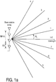
- Fig.1a shows an 8-level angular quantization grid resulting from the calculation of the angular response via an 8-point IDFT.
- Fig.1b illustrates the quantization diagram. Note that the directional sine is uniformly quantized.
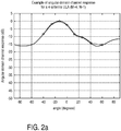
- Fig.2a and 2b show the amplitude of the angular domain response of a channel realization (normalized by the peak value) in a Cartesian and polar plot, respectively. Bullets represent the quantized version computed by eq. (1), while the solid line denotes the function of eq. (2). Note that in order to plot the angular response, knowledge of the antenna spacing is needed, which is necessary to associate the IDFT indices to angular values.
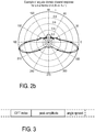
- Fig.3 shows a format of a control signal S in an uplink signaling channel as proposed herein: the first 3 bits are used to report the IDFT index, which is 7 (111) in the example, corresponding to the peak of the angular domain response.
- the second field contains the value of the amplitude of the angular response at the peak.
- the third optional field contain an indication of the angular spread: for example the terminal can count the number of IDFT points with amplitude within 3dB of the peak value, at either side of the peak. In the example this number is 1 (001).
- the BS can then derive an estimate of the angular spread of the main lobe at 3dB, which is roughly 25° as can be seen from Fig. 2a .
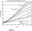
- Sub-urban macro with a single path propagation (briefly, SCM-SM1Path). This models a very spatially-correlated channel for each user, with nearly line-of-sight propagation.
- each UE performs channel vector quantization and reports the quantization index and the following:
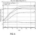
- B 4 and 8 bits respectively
- RVQ also for fewer quantization bits and performance is, within a fraction of dB, close to the Grassmannian codebooks.
- the Grassmannian codebooks have been generated by random search amongst vectors isotropically distributed in the M-dimensional complex unit sphere.
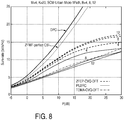
- the SCM channel model is evaluated with the "sub-urban macro” scenario and one propagation path (SCM-SMPath1 for short), and the "urban micro” scenario, ten paths (SCM-UmPath10 for short), respectively.
- the SCM-SMPath1 channel models a nearly line-of-sight propagation condition with local scattering at the receivers and very high spatial correlation.
- the SCM-UmPath10 models a rich scattering urban scenario. Because of the spatial correlation, i.e. "directional" properties in the angular domain, of these two channels, Grassmannian and random codebook are not well suited.
- these codebooks are designed specifically for uncorrelated channel vectors whose direction is isotropically distributed in the M-dimensional unit sphere.
- the correlation properties of the SCM channel are better captured by a Fourier codebook.
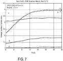
- Such a codebook structure is used for the CVQ scheme and TDMA in Figs. 6-9 .
- vector quantization using such codebook can be done very efficiently by DFT-transform.
- the entire codebook need not be stored in memory as the vector quantization operation boils down to a simple Fourier transform.
- Fig.7 and 9 the average number of allocated users is shown for the SCM-SMPath1 and SCM-UmPath10 channel models, respectively.
- Fig. 10 shows a flow diagram of an embodiment for a control method 100 for a communication network that has a transmitter T with an array of transmit antennas and a receiver R communicating with the transmitter T.
- the transmitter T is a Node B provided with MIMO technology in a cellular communication network according to the UMTS standards
- the receiver R is a mobile terminal attached to the communication network via the Node B.
- a Node B typically also comprises a receiver portion.
- the method 100 is started with the transmitter sending pilot information through each of the array of transmit antennas provided at the transmitter side, in step 102.
- the pilot signals are orthogonal between each antenna of the array of transmit antennas.
- the pilot signals transmitted to the receiver are used on the receiver side to perform channel measurements for a receive antenna of the receiver, at step 104.
- channel coefficients are determined for each element of the array of transmit antennas of the transmitter T from the output of the channel measurement.
- the determined channel coefficients are subjected to a reversible transform so as to obtain channel component coefficients, which are indicative of an individual weight of respective channel components in the transform domain, at step 108.
- a suitable reversible transform is an Inverse Discrete Fourier Transform (IDFT).
- IDFT Inverse Discrete Fourier Transform
- other reversible transforms can be used.
- Linear and orthogonal transforms are preferred because they reduce the computational complexity at the receiver.
- the transform domain in the present embodiment is an angular domain such that the channel components in the transform domain indicate different angles or angular intervals.
- the channel component coefficients determined in this embodiment form an ordered set of magnitude values associated with an angle or angular interval determined by an index order.
- the receiver R selects one or more of the channel components in the transform domain.
- the receiver ascertains and selects a channel component that has a channel component coefficient, which forms either an absolute or a relative maximum of magnitude in the set of channel component coefficients.
- the receiver R provides one or more preferred channel components, which are derived from the linear decomposition of the vector of channel measurements, and a magnitude of one or more channel components to the transmitter.
- the receiver communicates to the transmitter a control signal indicative of one preferred channel component and an estimate of a signal-to-interference-plus-noise ratio (SINR).
- SINR signal-to-interference-plus-noise ratio
- the receiver communicates to the transmitter control signal indicative of one preferred channel component.
- the transmitter T receives the control signal, and, at step 116, it constructs a beam pattern in the transform domain using the information received from the receiver R, with which step the method ends.
- the beam pattern may be constructed using information from more than one receiver.
- Fig. 11 shows a simplified block diagram of an embodiment of a receiver 200 suitable for performing the operations of the receiver in the control method of Fig. 10 .
- the receiver of Fig. 11 is shown only in that amount of detail, which is relevant for explaining the features of the technology disclosed by the present application.
- Known functionalities of a receiver for operation in a MIMO communication network are not shown for the sake of simplicity and conciseness of the present specification.
- the receiver 200 is designed for operation in the communication network described with reference to Fig. 10 and for performing a control-signaling method for a receiver that corresponds to the method steps performed by the receiver R in Fig. 10 .
- the receiver 200 has an array 202 of receive antennas, of which two receive antennas 204 and 206 are shown. In an alternative embodiment, the receiver 200 has only one receive antenna.
- the receiver 200 has a channel measurement unit 208, which on its input side is connected with the array of receive antennas 202.
- the channel-measurement unit 208 is on its output side connected with a transform unit 212.
- the transform unit 212 is connected with a selection unit 214, which in turn is connected with a control unit 216.
- the control unit is connected with a transmitter portion 218, which is connected on its output side with a transmit antenna 220.
- the units 208 to 216 can take the form of a receiver module 222, which can be used to update existing receiver structures with the technology described herein. As such, the receiver module 222 will have input and output ports 224, 226, and 228.
- the channel-measurement unit 208 performs a measurement of a channel coefficients for each of the array of transmit antennas at the transmitter on the basis of the received signal.
- the received signal used by the channel measurement unit is typically a pilot signal containing pilot information received from a MIMO transmitter (in the example of Fig. 10 : the Node B) via an array of transmit antennas of a MIMO transmitter.
- the channel measurements are performed for each antenna of the array of receive antennas 202.
- Channel coefficients obtained from the channel measurements are fed to the transform unit 212, which performs a reversible transform to the channel coefficients, preferably a linear and orthogonal transform, which is suitably a IDFT.
- the transform unit provides at its output channel component coefficients to the selection unit 214.
- the channel component coefficients indicate an individual weight of the respective channel components in the transform domain, which, as explained is suitably an angular domain.
- the selection unit 214 selects one or more channel components in the transform domain on the basis of the channel component coefficients received from the transform unit. The selection is suitably based on a criterion, which allows to determine either an absolute or a relative maximum of magnitude in the channel component coefficients received from the transform unit 212.
- the selection unit then provides the selected channel component information to the control unit 216.
- the control unit 216 forwards to the transmit portion 218 one or more preferred channel components, as selected by the selection unit 216, or a magnitude of one or more channel component coefficients, or both.
- the control unit provides one preferred channel component, as selected by the selection unit 216, and an estimate of the SINR. This information is processed by the transmit portion 218 for transmitting it to the transmitter (not shown in Fig. 11 ) via the transmit antenna 220.
- Fig. 12 shows a simplified block diagram of a transmitter 300 suitable for performing the operations of the transmitter in the control method of Fig. 10 .
- the transmitter 300 of Fig. 12 is shown in only an amount of detail, which is relevant for explaining the features of the technology disclosed by the present application.
- Known functionalities of a transmitter for operation in a MIMO communication network are not shown for the sake of simplicity and conciseness of the present specification.
- the transmitter 300 has an array 302 of transmit antennas and receive antennas, which are shown as a single combined array in Fig. 12 .
- the transmitter further has a transmitter control module 304, which is configured to receive from the receive antennas a control signal indicative of one ore more preferred channel components and a magnitude of the one ore more channel components.
- control signal has been described with reference to Figs. 3 , 10 and 11 in further detail.
- the received control signal is indicative of one preferred channel component and an estimate of the SINR.
- the transmitter-control unit 304 constructs beam-pattern control data in the transform domain and provides it to the antenna array 302 in the form of transmit control signals to be used during transmission of data to a receiver, from which the external control signal indicative of the one ore more preferred channel components were received.
- Those functional blocks of the transmitter, which are responsible for generation of transmit signals to be fed to the MIMO antenna array 302 are omitted in the block diagram of Fig. 12 .
- a single unit may fulfill the functions of several items recited in the claims.
- the mere fact that certain measures are recited in mutually different dependent claims does not indicate that a combination of these measured cannot be used to advantage.
- a computer program may be stored/distributed on a suitable medium, such as an optical storage medium or a solid-state medium supplied together with or as part of other hardware, but may also be distributed in other forms, such as via the Internet or other wired or wireless telecommunication systems.
- a suitable medium such as an optical storage medium or a solid-state medium supplied together with or as part of other hardware, but may also be distributed in other forms, such as via the Internet or other wired or wireless telecommunication systems.
Description
- The present invention relates to:
- a control method for a communication network that has a transmitter with an array of transmit antennas and that has at least one receiver communicating with the transmitter;
- a receiver module for a communication network with a transmitter having an array of transmit antennas;
- a control-signaling method for a receiver in a communication network with a transmitter having an array of transmit antennas for transmission to at least one receiver;
- a computer program product, containing executable program code, which is configured to cause a receiver to carry out a control-signaling method for a receiver in a communication network that has a transmitter with an array of transmit antennas for transmission at least to one receiver;
- a receiver for a communication network with a transmitter having an array of transmit antennas;
- a transmitter control module for a transmitter having an array of transmit antennas for transmission to at least one receiver;
- a transmitter having an array of transmit antennas for transmission to at least one receiver;
- a transmitter control method for a transmitter having an array of transmit antennas for transmission to at least one receiver;
- a computer program product, containing executable program code, which is configured to cause a transmitter having an array of transmit antennas for transmission to at least one receiver to carry out a transmitter control method;
- a communication network, comprising a transmitter having an array of transmit antennas for transmission to at least one receiver; and
- a control signal for a communication network that has a transmitter with an array of transmit antennas and that has at least one receiver communicating with the transmitter.
- Multiple-input multiple-output (MIMO) is a technology for next generation wireless systems to enhance the capacity and robustness of the communication link. MIMO technology is based on the presence of multiple transmit antennas and multiple receive antennas in the communication link. Application of MIMO technology is envisioned for cellular communication, broadband wireless access, as well as for wireless local area networks (WLANs). A plurality of two or more transmit antennas is also referred to as an array of transmit antennas herein.
- The benefits of MIMO communication are obtained through a combination of antenna arrays that provide spatial diversity from the propagation channel and algorithms that can adapt to the changing multivariate channel.
- In future mobile systems and in the long-term evolution of the Universal Mobile Telecommunication System (UMTS LTE) the use of multiple-antenna techniques will become increasingly important to meet spectral efficiency requirements. A significant gain in spectral efficiency can be achieved in a downlink transmission by multiplexing multiple codewords in the spatial domain to either a single user or multiple users sharing the same time-frequency resource block. These single-user or multi-user MIMO schemes exploiting the multiplexing gain of multi-antenna transmission are sometimes referred to as spatial division multiplexing (SDM) and spatial division multiple access (SDMA) techniques. An SDMA scheme enables multiple users within the same radio cell to be accommodated on the same frequency or time slot. The realization of this technique can be accomplished by using an antenna array, which is capable of modifying its time, frequency, and spatial response by means of the amplitude and phase weighting and an internal feedback control.
- Beamforming is a method used to create a radiation pattern of the antenna array by constructively adding the phases of the signals in the direction of the communication targets (terminal devices) desired, and nulling the pattern of the communication targets that are undesired or interfering.
- In this context, the beamforming vector plays an important role. For purposes of illustration of the meaning of the beamforming vector, in an exemplary single-user communication system employing transmit beamforming and receive combining, assuming that signaling is done using M transmit and N receive antennas, the input-output relationship of this communication system is given by:

- One of the challenges in the design of the beamforming vectors for SDM and SDMA techniques is the need for the base station to know the channels for all the users and receiving antennas of each user. This would require a large amount of feedback to be signaled from the users to the base station.
- Solutions have been proposed to reduce this signaling information by introducing a codebook of few possible beamforming matrices. Each user then applies a greedy procedure to select one or more preferred beamforming vectors out of the codebook, by evaluating the Signal-to-Noise-Ratios (SINRs) of different beamforming combinations. Thus, each user has to signal one or several indexes of the preferred vector or vectors, respectively, plus one or more Channel-Quality-Indicator (CQI) values, indicating the corresponding SINRs.
- An issue with codebook-based solutions is that the beamforming vectors are not jointly optimized according to the channel conditions. The base station uses the feedback information from the users only to schedule transmission to the set of users reporting the best CQI values.
- Alternatively, significant gain in the cell throughput can be achieved if the base station could implement an ad-hoc design of the beamformer. This is possible, for example, if the users report all the channel coefficients, after some quantization operation. However, this requires signaling as many complex values as the product, MN, between the number M of transmit antennas and the number N of receive antennas per user.
-
US 20060094373 discloses a closed-loop signalling method which controls multiple transmit beams. The method also includes transmitting a plurality of beams from a first transceiver via a plurality of transmission channels to a second transceiver, evaluating, at the second transceiver, characteristics of the plurality of transmitted beams received at the second transceiver. - The paper entitled "Equal gain transmission in multiple-input multiple-output wireless systems" describes a multiple-input multiple-output MIMO system and its ability to provide substantial gains in capacity and quality.
- 3GPP TSG-RAN WG1 #44 - R1-060457 describes single and multiple codeword schemes with precoding.
-
WO 2006006770 discloses an apparatus and method for transmitting and receiving packet data using multiple antennas in a wireless communication system. In a wireless communication system using multiple antennas, the apparatus and method can efficiently transmit and receive packet data according to channel conditions without a waste of transmission bandwidth. - The invention is defined by the appended claims. According to a first aspect of the invention a control method for a communication network that has a transmitter with an array of transmit antennas and that has at least one receiver communicating with the transmitter is provided. The method comprises the steps:
- A) at the receiver:
- performing a channel measurement for a receive antenna of the receiver using a signal transmitted from the transmitter to the receiver;
- determining the channel coefficients for each of an array of transmit antennas at the transmitter from an output of the channel measurement;
- applying a reversible transform from a spatial to an angular domain using an Inverse Discrete Fourier Transform, IDFT, to the channel coefficients, thus ascertaining channel component coefficients indicative of the individual weight of respective channel components in the angular domain;
- selecting one or more channel components in the angular domain;
- communicating to the transmitter a control signal, which is indicative of either:
- 1) one or more preferred channel components, derived from the linear decomposition of the vector of channel measurements, and a magnitude of one or more channel components, or, alternatively,
- 2) one preferred channel component and an estimate of the SINR or, alternatively,
- 3) one preferred channel component;
- B) at the transmitter:
- receiving the control signal; and
- constructing a beam pattern in the angular domain using the information received from the receiver.
- The method of the invention allows an advantageous control of a beamforming process on the transmitter side, based on communicating channel component coefficients indicative of the individual weight of respective channel components in an angular domain from the receiver to the transmitter.
- The method overcomes a main issue with codebook-based solutions, namely, that beamforming vectors are not jointly optimized according to the channel conditions. In codebook-based implementations, the transmitter typically uses feedback information from the receivers, like wireless mobile terminal devices, only to schedule transmission to the set of users reporting the best CQI values.
- Significant gain in the cell throughput can be achieved by the method of the invention because the transmitter can implement an ad-hoc design of a beamformer. This is possible, because the receiver reports channel component coefficients as defined by the alternatives 1) to 3) above, and preferably in quantized form. In the prior art, this would require signaling as many complex values as the product, MN, between the number of transmit antennas, M, and receive antennas, N, per receiver. In embodiments of the method of the first aspect of the invention, however, it suffices to extract some channel state information (CSI) bits from channel measurements at the receiver side. This information is enough to enable the transmitter, for instance a base station, to design a robust beamforming matrix. The amount of feedback bits required is exactly the same as in the codebook-based techniques.
- Note that the terms transmitter and receiver are chosen with reference to the role of the respective device in a communication. Generally, the transmitter of the claims can also take the role of a receiver in a different communication, and the receiver of the claims can also take the role of the transmitter in a different communication. Both devices can be transceiver devices that are configured to perform the method steps associated with the transmitter and configured to perform the method steps associated with the receiver. A preferred configuration for an application of the method of the invention is that of a base station forming the transmitter and a mobile terminal forming the receiver in a MIMO communication network.
- In the following, embodiments of the control method of the first aspect of the invention will be described. Unless explicitly described as alternatives, the embodiments can be combined with each other.
- In one embodiment performing a channel measurement comprises measuring pilot information transmitted from each of the array of transmit antennas at the transmitter. Preferably, the pilot signals are designed to be orthogonal between each antenna of the array of transmit antennas.
- Advantageously, the reversible transformation applied to the channel coefficients is linear and orthogonal; this helps reduce the computational complexity at the receiver. The transform comprises an Inverse Discrete Fourier Transform (IDFT). The channel components in the angular domain indicate different angles or angular intervals. The channel-component coefficients in this embodiment can take the form of an ordered set of index values, indicating a magnitude associated with an angle or angular interval determined by the index order.
- Preferably, thus, the feedback information communicated from the receiver to the transmitter may comprise one or more preferred receiving directions determined from data in the angular domain. This feedback information may be quantized as an integer indexing an angular quantization grid.
- In one particular embodiment, the transform is performed in accordance with the equation

- This is to be understood as follows: Let h denote an M-dimensional vector with components ĥm of channel measurements that the receiver has derived for a given receiving antenna, for instance by sensing common pilots embedded in a resource block received from the transmitter. Furthermore, M is the number of transmit antennas at the transmitter. It is assumed without restriction that n bits of an uplink signaling channel are reserved for communicating the channel-component coefficients, for instance in the form of index values, such that an angular quantization grid provides L = 2n levels. The receiver or, if multiple receivers are present, each receiver computes an L-point IDFT of ĥ, and takes the absolute value, i.e. forms a vector ĥ a with elements ĥa,l as given by equation (1). This vector ĥ a represents a quantized version of the angular-domain response amplitude of the channel.
- It should be noted that the IDFT is a suitable transform. Other transforms could be used that are a linear, reversible and orthogonal.
- A further embodiment comprises a step of determining a measure of uncertainty of the channel component coefficients in the angular domain at the receiver after applying the linear and reversible orthogonal transform to the channel coefficients. For example this could be determined from the transformed coefficients in the form of a beamwidth. As another example, this could be determined from the range of variation of sets of channel coefficients or channel component coefficients obtained at different times or at different frequencies.
- Another embodiment comprises a step of applying a filter to the channel component coefficients in the angular domain at the receiver. This embodiment forms one way of including the effects of uncertainty in the measured channel coefficients. In the case of the angular domain, use of a smoothing filter is equivalent to including angular uncertainty.
- In another embodiment, selecting one or more channel components in the angular domain comprises ascertaining and selecting a channel component that has a channel component coefficient, which forms an either absolute or relative maximum of magnitude in the set of channel component coefficients. With reference to the embodiment, in which the channel component coefficients belong to the angular domain and are indicative of a magnitude in a particular angular direction, the embodiment forms a direction finding technique. Other direction finding techniques could be employed
- For a beamforming process envisaged, which in one embodiment is based on a covariance matrix of the channel coefficients, the phase of a single peak is not required. In the case of more than one peak, however, the phase difference between peaks would be required in order to enable to correctly recover an estimate of the channel coefficients and/or covariance matrix. A further embodiment therefore comprises:
- ascertaining more than one relative maximum of magnitude in the set of component coefficients;
- measuring an amplitude of the respective relative maxima;
- measuring a phase difference between the channel components forming the relative maxima; and
- measuring a lower-bound estimate of the signal-to-interference-plus-noise ratio (SINR) given by the following expression. Let ∥ĥ∥ be the Euclidean norm of the vector of channel measurements, and


- In the case of multiple peaks phase information would be included with the magnitudes in the communicating step.
- In one embodiment, communicating the control signal to the transmitter comprises communicating via a radio link, wherein control information comprised by the control signal, as defined in alternatives A), 1) to 3), mentioned above, is preferably provided in quantized form.
- In a further embodiment the possible quantized channel representations are stored in a codebook, which would allow more flexibility in the designing the channel quantizer to match the expected channel conditions. To support convenient codebook design, the codebook may be arranged such that the entries form unitary matrices. For any codebook (unitary or not) the selection of a preferred channel representation is made by finding the index of the codebook entry with the highest value of estimated SINR. This corresponds to identifying a preferred codebook index. In estimating the SINR, a range of assumptions may be made about the interference from other transmissions, including the presence of transmissions on other beams and the precoding applied to these transmissions. Preferably these different assumptions would correspond to different decisions at the transmitter, for example to schedule transmissions to different users on different beams. The transmissions on other beams may use precoding selected from a codebook, which would have the advantage of limiting the number of possible beamformers, which would have to be implemented at the transmitter and the number of different possible beams, which would need to be taken into account at the receiver when considering assumptions about interference.
- At the receiver, since the codebook index corresponding to the highest estimated SINR will in general depend on the assumed interference, different preferred codebook indices may be determined for different interference assumptions, In the case of a unitary codebook the indices may be constrained to be from the same unitary matrix (which limits the number of possibilities that need to be considered, leading to lower receiver complexity, but lower performance) or allowed to be from different unitary matrices (which is more flexible, but may lead to more signaling overhead to cover the additional possibilities).
- In general, to enable the transmitter to decide on the scheduling of transmissions to different users and the transmission details (e.g. bit rate, coding, time/frequency domain resource allocation, use of beamforming/precoding), one or more of preferred codebook indices for different interference assumptions and some or all of the corresponding CQI values may be communicated to the transmitter. The set of assumptions to be considered at the receiver may be pre-determined, for example as a part of the system design, or configurable by signaling, since there will in general be a trade-off between increasing performance by considering a wider range of assumptions and the associated additional complexity and signaling overheads (e.g. from sending more indices and CQI values to the transmitter).
- For multiple receive antennas receiver, the method of the first aspect of the invention can be extended by executing it once for each of the receive antennas. In one embodiment, therefore, the channel measurement is performed for each of an array of receive antennas at the receiver.
- The same procedure can be applied for virtual receive antennas formed by linear combinations of signals from more than one physical antenna.
- Preferably, the step of communicating to the transmitter comprises communicating a set of channel quality indicator (CQI) bits.
- On the transmitter side, constructing a beam pattern in the angular domain in one embodiment comprises constructing a transmit signal impulse in at least one of the one or more preferred channel components, where the preferred channel component can for instance form preferred angular directions.
- In this embodiment, constructing a beam pattern in the angular domain preferably comprises constructing the transmit signal impulse with an amplitude determined according to the magnitude of the channel component coefficients.
- Another embodiment further comprises a step of determining a measure of uncertainty in the angular domain of the channel component coefficients at the transmitter after receiving the control signal. Determining a measure of uncertainty in the angular domain of the channel component coefficients at the transmitter can for example comprise evaluating a range of variation of the preferred channel components communicated at different times or at different frequencies.
- Another embodiment of the method of the first aspect of the invention comprises applying a filter to the beam pattern in the angular domain. For example, this filter could be determined according to an obtained measure of uncertainty.
- Another embodiment comprises designing a beamformer for transmission from the transmitter to the receiver in dependence on the constructed beam pattern in the angular domain. Designing a beamformer can for instance comprise applying an inverse of the linear and reversible orthogonal transform, e.g., a Discrete Fourier Transform (DFT) that forms an inverse to the IDFT mentioned earlier, to the channel component coefficients.
- Furthermore, the beamformer design process could be based on coefficients received from more than one receiver. Thus, designing a beamformer is in another embodiment performed in additional dependence on channel component coefficients received from at least one second receiver different from the receiver.
- In a further embodiment the beamformer is restricted to be one of a set of pre-coding coefficients from a pre-determined codebook. Limiting the flexibility of the pre-coding may lead to lower complexity at the transmitter, and may lead to less signaling overhead (e.g. if the codebook index is signaled to the receiver, rather than unrestricted values of pre-coding coefficients). For convenient design, the codebook may be constructed from unitary matrices.
- In an embodiment with codebooks at both transmitter and receiver, the codebooks may be different. This means that the contents and size of these codebooks can be independently designed to optimized the trade-off between such factors as system performance vs. complexity and signaling overhead.
- Note that beamforming techniques using the channel covariance matrix do not require the absolute phase of the channel coefficients.
- Note that in some cases a channel can be assumed to be reciprocal (or approximately reciprocal) between uplink and downlink, so measurements may then be made in one direction and applied in the other. In this case the following steps would not be required:
- selecting one or more channel components in the angular domain;
- communicating to the transmitter a control signal, which is indicative of either:
- 1) one or more preferred channel components, derived from the linear decomposition of the vector of channel measurements, and a magnitude of one or more channel components, or, alternatively,
- 2) one preferred channel component and an estimate of the SINR or, alternatively,
- 3) one preferred channel component;
- constructing a beam pattern in the angular domain using the information received from the receiver during the communicating step;
- Note that a vector quantizer can be applied to the channel measurements, instead of performing the steps:
- selecting one or more channel components in the angular domain;
- measuring an amplitude of respective relative maxima in the set of channel component coefficients;
- measuring a phase difference between the channel components forming the relative maxima.
- However, this would involve a higher process complexity, and because phase information is not required in many cases, may involve signaling a larger number of bits.
- In a MIMO communication network, a transmitting station selects a beamforming matrix based on feedback information from one or more receiving stations. According to the invention, the feedback information is derived from an Inverse Discrete Fourier Transform (IDFT) of a measure of channel characteristics made on a signal received at the receiving station.
- Optionally the feedback information may comprise an indication of peak magnitude of signals in the angular domain.
- Optionally the feedback information may comprise an indication of angular uncertainty in the angular domain.
- Optionally a filter may be applied to the data in the angular domain.
- According to a second aspect of the invention, a control signaling method for a receiver in a communication network with a transmitter having an array of transmit antennas for transmission of user data to the receiver is provided, comprising:
- performing a channel measurement for a receive antenna of the receiver;
- determining the channel coefficients for each of an array of transmit antennas at the transmitter from an output of the channel measurements;
- applying a reversible transform from a spatial to an angular domain using an Inverse Discrete Fourier Transform, IDFT, to the channel coefficients, thus ascertaining channel component coefficients indicative of the individual weight of respective channel components in the angular domain;
- selecting one or more channel components in the angular domain;
- communicating to the transmitter a control signal indicative of either:
- 1) one or more preferred channel components, derived from a linear decomposition of a vector formed by the channel coefficients, and a magnitude of the one or more channel components, or, alternatively,
- 2) one preferred channel component and an estimate of a quantity indicative of a signal-to-interference-plus-noise ratio SINR, or, alternatively,
- 3) one preferred channel component.
- Embodiments of the control signaling method of the second aspect of the invention correspond to those above described embodiments of the method of the first aspect of the invention, which further specify method steps performed at the receiver. A third aspect of the invention is a computer program product, containing executable program code, which is configured to implement a control signaling method for a receiver in a communication network that has a transmitter having an array of transmit antennas for transmission of user data to the receiver, the control signaling method comprising the steps:
- performing a channel measurement for a receive antenna of the receiver;
- determining the channel coefficients for each of an array of transmit antennas at the transmitter from an output of the channel measurements;
- applying a reversible transform from a spatial to an angular domain using an Inverse Discrete Fourier Transform, IDFT, to the channel coefficients, thus ascertaining channel component coefficients indicative of the individual weight of respective channel components in the angular domain;
- selecting one or more channel components in the angular domain;
- communicating to the transmitter a control signal indicative either:
- 1) one or more preferred channel components, derived from a linear decomposition of a vector formed by the channel coefficients, and a magnitude of the one or more channel components, or, alternatively,
- 2) one preferred channel component and an estimate of a quantity indicative of a signal-to-interference-plus-noise ratio SINR, or, alternatively,
- 3) one preferred channel component.
- In particular, the computer program product can be a receiver control software or a firmware stored on a data medium or implemented in a receiver, or an update software for a previous control software or firmware on a data medium.
- Embodiments of the computer program product of the third aspect of the invention contain executable program code, which is configured to implement a control signaling method for a receiver according to embodiments of the method of the first aspect of the invention which further specify method steps performed at the receiver. According to a fourth aspect of the invention, a receiver module for a communication network with a transmitter having an array of transmit antennas is provided. The receiver module comprises:
- a channel-measurement unit, which is configured to be connected with a receive antenna of a receiver and configured to perform a measurement of a physical quantity indicative of a channel quality for the receive antenna on the basis of the received signal and to provide an output signal indicative of the measurement result result in the form of channel coefficients for each of the array of transmit antennas at the transmitter;
- a transform unit, which is connected with the channel-measurement unit and configured to apply a linear and reversible orthogonal transform from a spatial to an angular domain using an Inverse Discrete Fourier Transform, IDFT, to the channel coefficients, and to provide at its output channel component coefficients indicative of the individual weight of respective channel components in the angular domain;
- a selection unit, which is connected with the transform unit and configured to select one or more channel components in the angular domain on the basis of the channel component coefficients received from the transform unit;
- a control unit, which is configured to generate and provide at its output a control signal indicative of either:
- 1) one or more preferred channel components, derived from a linear decomposition of a vector formed by the channel coefficients, and a magnitude of the one or more channel components, or, alternatively,
- 2) one preferred channel component and an estimate of a quantity indicative of a signal-to-interference-plus-noise ratio SINR, or, alternatively,
- 3) one preferred channel component.
- The receiver module can form a component of a receiver or an independently traded add-on module to an existing receiver of a previous generation.
- In the following, embodiments of the receiver module will be described. The embodiments can be combined with each other, unless stated otherwise explicitly. Further details and advantages of the embodiments can be found in the context of the description of embodiments of the method of the first aspect of the invention, which further specify method steps performed at the receiver.
- In one embodiment, the channel-measurement unit is configured to perform a channel measurement by measuring pilot information transmitted from each of the array of transmit antennas at the transmitter.
- In a further embodiment the channel-measurement unit is further configured to determine a measure of uncertainty of the channel component coefficients in the angular domain.
- In another embodiment, the channel-measurement unit is further configured to apply a filter to the channel component coefficients in the angular domain.
- In one embodiment, the control unit is configured to generate and provide at its output an uncertainty indicator that forms a measure of uncertainty of a channel component coefficient in the angular domain.
- The selection unit is in another embodiment configured to ascertain and select a channel component that has a channel component coefficient, which forms an either absolute or relative maximum of magnitude in the component coefficients received from the transform unit.
- In a further embodiment, the selection unit is configured to:
- ascertain whether more than one relative maximum of magnitude is present in the set of channel component coefficients received from the transform unit;
- measure an amplitude of respective relative maxima in the set of channel component coefficients received from the transform unit;
- measure a phase difference between the channel components forming the relative maxima.
- The control unit is in one embodiment configured to communicate to the transmitter in quantized form one or more preferred channel components or a magnitude of one or more channel component coefficients via a radio link.
- In a further embodiment, the channel-measurement unit is configured to:
- be connected with an array of receive antennas; and to
- perform the channel measurement for each antenna of the array of receive antennas.
- In another embodiment, the control unit is preferably configured to communicate to the transmitter the control signal form in the form of a set of channel quality indicator bits.
- According to a fifth aspect of the invention, a receiver for a communication network with a transmitter having an array of transmit antennas is provided, comprising:
- at least one receive antenna, which is configured to receive a signal transmitted by the array of transmit antennas of the transmitter;
- a receiver module according to claim the fourth aspect of the invention or one of its embodiments described herein.
- The receiver comprises in one embodiment an array of receive antennas.
- In another embodiment, that can be combined with any of the other embodiments, the receiver forms a mobile terminal device for wireless communication.
- In another embodiment, the receiver also comprises a transmitter according a seventh aspect of the invention or one of its embodiments, which will be described below.
- According to a sixth aspect of the invention, a transmitter control module is provided, which is configured:
- to receive from an external device a control signal indicative either:
- 1) one or more preferred channel components, derived from a linear decomposition of a vector formed by the channel coefficients, and a magnitude of the one or more channel components, or, alternatively,
- 2) one preferred channel component and an estimate of a quantity indicative of a signal-to-interference-plus-noise ratio SINR, or, alternatively,
- 3) one preferred channel component.
and
- to construct and provide at its output beam-pattern control data in the angular domain using the information received from the external device.
- The transmitter control module can form a component of a transmitter or an independently traded add-on module to an existing receiver of a previous generation.
- In the following, embodiments of the transmitter control module will be described. The embodiments can be combined with each other, unless stated otherwise explicitly. Further details and advantages of the embodiments can be found in the context of the description of embodiments of the method of the first aspect of the invention, which further specify method steps performed at the transmitter.
- In one embodiment, the transmitter control module is further configured to:
- construct and provide beam-pattern control data for a beam pattern in the form of a transmit signal impulse in at least one of the one or more preferred channel components.
- Another embodiment of the transmitter control module further comprises a channel-evaluation unit, which is configured to generate and provide at its output an uncertainty indicator forming a measure of uncertainty of the channel component coefficients in the angular domain.
- According to a seventh aspect of the invention, a transmitter is provided, comprising:
- an array of transmit antennas; and
- a transmitter control module according to the sixth aspect of the invention or one of its embodiments described herein.
- In one embodiment the transmitter forms a base station in a mobile-communication network.
- In a further embodiment, the transmitter also comprises a receiver according to the fifth aspect of the invention or one of its embodiments.
- According to an eighth aspect of the invention, a transmitter control method is provided, comprising the steps:
- receiving a control signal indicative of one or more preferred channel components or a magnitude of one or more channel component coefficients, or both, in quantized form;
- constructing a beam pattern in the angular domain using information contained in the control signal.
- Embodiments of the transmitter control method correspond to those embodiments described in the context of the description of embodiments of the method of the first aspect of the invention, which further specify method steps performed at the transmitter.
- According to a ninth aspect of the invention, a computer program product is provided, containing executable program code, which is configured to implement a transmitter control method for a transmitter having an array of transmit antennas for transmission of user data to the receiver, the transmitter control method comprising the steps:
- receiving a control signal indicative of one or more preferred channel components or a magnitude of one or more channel component coefficients, or both, in quantized form;
- constructing a beam pattern in the angular domain using information contained in the control signal;
- Embodiments of the computer program product of the ninth aspect of the invention contain executable program code, which is configured to implement a transmitter control method corresponding to those embodiments described in the context of the description of embodiments of the method of the first aspect of the invention, which further specify method steps performed at the transmitter. In particular, the computer program product can be a transmitter control software or a firmware stored on a data medium or implemented in a transmitter, or an update software for a previous transmitter control software or firmware on a data medium.
- A tenth aspect of the invention is formed by a communication network, comprising a transmitter according to the eighth aspect of the invention or one of its embodiments and a receiver according to the fifth aspect of the invention or one of its embodiments.
- The communication network is in one embodiment a cellular wireless network, preferably according to a Universal Mobile Communication Standard. Communication between network entities of the communication network preferably employs a Multiple-input multiple-output (MIMO) technology.
- An eleventh aspect of the invention is formed by a control signal for a communication network that has a transmitter with an array of transmit antennas and that has at least one receiver communicating with the transmitter, the control signal comprising control information indicative of either:
- 1) one or more preferred channel components, derived from a linear decomposition of a vector formed by the channel coefficients, and a magnitude of the one or more channel components, or, alternatively,
- 2) one preferred channel component and an estimate of a quantity indicative of a signal-to-interference-plus-noise ratio SINR, or, alternatively,
- 3) one preferred channel component.
- The control information can for instance be provided in quantized form.
- Embodiments of the invention are also defined in the dependent claims.
- The invention will now be explained in more detail with reference to the drawings in which:
-
Fig. 1a shows an 8-level angular quantization grid resulting from the calculation of an angular response via an 8-point IDFT. -
Fig. 1b illustrates the quantization diagram. -
Figs. 2a and2b show the amplitude of the angular domain response of a channel realization, normalized by the peak value, in a Cartesian and polar plot, respectively. -
Fig. 3 shows a format of a control signal used in an uplink signaling channel. -
Figs. 4 to 9 show numerical results of simulating the system and method. -
Fig. 10 shows a flow diagram of an embodiment for a control method for a communication network that has a transmitter with an array of transmit antennas and a receiver communicating with the transmitter. -
Fig. 11 shows a block diagram of an embodiment of a receiver suitable for performing the operations of the receiver in the control method ofFig. 10 . -
Fig. 12 shows a schematic block diagram of a transmitter suitable for performing the operations of the transmitter in the control method ofFig. 10 . - As an exemplary communication system we consider a cellular downlink transmission towards K receivers, with a single receiving antenna each. The signal at a generic receiver can expressed as

- Let us indicate with ĥ the M-dimensional vector of channel measurements that the receiver, which hereinafter will also be referred to as the terminal, has derived for a given receiving antenna, by sensing the common pilots embedded in the resource block. M is the number of transmit antennas at the transmitter, which hereinafter will also be referred to as the base station or, in short, BS. We assume that n bits of the uplink signaling channel are reserved for reporting the index values, such that the angular quantization grid provides L = 2n levels. Each terminal computes an L-point IDFT of ĥ, and take the absolute value, i.e. forms a vector ĥ a with elements

- This vector represents a quantized version of the angular-domain response amplitude of the channel ĥ, given by

- The terminal then reports one or more points of the function ĥ a,l , typically the peak index and the peak value, computed as


- Alternatively, the terminal may report an estimate of the SINR, for instance a lower bound estimate of the SINR, provided by:

- Reporting the lower-bound estimate of the SINR brings a surprisingly high efficiency to the method and system of the invention, as witnessed from numerical simulation results. This reporting can be done for instance with help of some of the bits of channel quality indicator bits (CQI).
- This estimate can be made under a plurality of assumptions. For example, this estimate could be done under the assumption that the transmitter forms the beam pattern by using zero forcing beamforming.
- In addition, the terminal may report an estimate of the angular spread, by measuring the width of the peak lobe. This can be signaled, for example, by reporting the number of points of ĥa,l falling within 3dB attenuation at either side of the peak (see the example hereafter).
- Note that the transformation for the angular-domain representation of the channel measurements is an IDFT because of the geometry of the transmit array, which is assumed to be an ULA (uniform linear array). Different geometries imply different transformations from the spatial to the angular domain. However, the terminal could still be reporting channel measurements in terms of angular indices, under the assumption of a transmit ULA, independently of the actual array geometry. It is, then, up to the BS to associate these indices with the correct angles and corresponding unit spatial signatures, depending on the array geometry. This step may be needed for the BS to be able to steer a beam in the correct angular direction.
- Note that the terminal does not need to know the antenna spacing at the transmitter. However, this parameter is known to the BS, hence it can associate the reported peak index with a physical propagation angle. In fact, the IDFT operation encompasses a uniform quantization of the directional sine, Ω = sin φ, with step size


- The angular information is derived by the BS as follows

- Note that if the antennas are densely spaced (Δ < 1/2) the equation above may have no solution. However, this is a case of very little practical interest, as the antenna arrays are usually designed with Δ ≥ 1/2 for maximum uncorrelation properties. Moreover, as the antenna spacing decreases below half a wavelength, the radiation pattern becomes close to that of an omnidirectional antenna, and the directional information becomes less significant.
- In the following, an example will be described with reference to
Figs.1a through 2b in parallel. - Let us consider a 4-antenna ULA covering a 120° cell sector. The normalized antenna spacing is set to

-
Fig.1a shows an 8-level angular quantization grid resulting from the calculation of the angular response via an 8-point IDFT.Fig.1b illustrates the quantization diagram. Note that the directional sine is uniformly quantized.Fig.2a and2b show the amplitude of the angular domain response of a channel realization (normalized by the peak value) in a Cartesian and polar plot, respectively. Bullets represent the quantized version computed by eq. (1), while the solid line denotes the function of eq. (2). Note that in order to plot the angular response, knowledge of the antenna spacing is needed, which is necessary to associate the IDFT indices to angular values. -
Fig.3 shows a format of a control signal S in an uplink signaling channel as proposed herein: the first 3 bits are used to report the IDFT index, which is 7 (111) in the example, corresponding to the peak of the angular domain response. The second field contains the value of the amplitude of the angular response at the peak. The third optional field contain an indication of the angular spread: for example the terminal can count the number of IDFT points with amplitude within 3dB of the peak value, at either side of the peak. In the example this number is 1 (001). The BS can then derive an estimate of the angular spread of the main lobe at 3dB, which is roughly 25° as can be seen fromFig. 2a . - We have compared the channel vector quantization (CVQ) technique and PU2RC in terms of average throughput and average number of active users per sub-carrier use, where average is w.r.t. the ensemble of independently generated channel matrices H. We have considered two different channel models.
- Independent Rayleigh fading. The elements of H are i.i.d. proper Gaussian random variables ∼CN(0,1). This model generates completely uncorrelated channels in space for each user.
3GPP spatial channel model (SCM) [13]. We report results for two opposite scenarios. - Sub-urban macro, with a single path propagation (briefly, SCM-SM1Path). This models a very spatially-correlated channel for each user, with nearly line-of-sight propagation.
- Urban micro, with 10-path propagation (briefly, SCM-Um10Path). This simulates a rich scattering environment with low spatial correlation.
- We consider the case of M=4 transmit antennas and K=20 single-antenna users. We assume that CSI from the UE's is sent to the Node B on zero-delay, error-free feedback channels and that each UE has perfect knowledge of its channel and no knowledge of the others'. Moreover, we assume that a codebook of N M-dimensional vectors is known to both the Node B and the UE's, and that each UE feeds back a log(N) bit index and an analog (i.e. unquantized) real CQI value.
- As a baseline reference to evaluate the spatial multiplexing gain of the MU-MIMO techniques, we consider a TDMA-type of system where for each channel instance the transmitter selects the user with the best achievable rate. In this baseline system each UE performs channel vector quantization and reports the quantization index and the following:
- CQI

- For comparison, we have also plotted the dirty paper coding (DPC) sum-rate capacity curve and the achievable throughput for ZF beamforming with water-filling power allocation across users (briefly, ZFWF), with greedy user selection and perfect CSI available at the transmitter.
- The first case (
Fig.4 ) is the Rayleigh fading channel model, i.e. spatially uncorrelated channels, with B=4,8 and 12 quantization bits. For the CVQ technique and the baseline TDMA, we have used Grassmannian codebooks G(4,1,16) and G(4,1,256) for B=4 and 8 bits respectively, while RVQ is used for B=12 bits. We have tried RVQ also for fewer quantization bits and performance is, within a fraction of dB, close to the Grassmannian codebooks. We recall that the Grassmannian codebooks have been generated by random search amongst vectors isotropically distributed in the M-dimensional complex unit sphere. We can see that PU2RC performance loses out to TDMA and CVQ for all SNR and quantization levels. For 8-bit quantization and upwards, the CVQ technique, with either Grassmann codebooks or RVQ, provides the best performance in the whole SNR range. One clear issue with a PU2RC-type of scheme is that the multiplexing gain is bounded above by one in the limit of large codebooks. This is because, if p=1/L=M/2B is the probability that a user selects a given beamforming matrix in the codebook, the probability of l out of K users selecting the same matrix is a binomial random variable with parameters (p, K), β(p,K), and mean valuel = Kp. Hence the average number of users selecting the same beamforming matrix decreases exponentially with the number of quantization bits B. Eventually, for large B, if K is kept constant, only a single user will ever be allocated. This can be clearly seen inFig.5 where the average number of active users is plotted versus SNR. On the other hand user allocation for CVQ gradually increases with the SNR and with B up to a maximum of 4. - In
Fig. 6 and8 the SCM channel model is evaluated with the "sub-urban macro" scenario and one propagation path (SCM-SMPath1 for short), and the "urban micro" scenario, ten paths (SCM-UmPath10 for short), respectively. The SCM-SMPath1 channel models a nearly line-of-sight propagation condition with local scattering at the receivers and very high spatial correlation. The SCM-UmPath10 models a rich scattering urban scenario. Because of the spatial correlation, i.e. "directional" properties in the angular domain, of these two channels, Grassmannian and random codebook are not well suited. In fact, these codebooks are designed specifically for uncorrelated channel vectors whose direction is isotropically distributed in the M-dimensional unit sphere. The correlation properties of the SCM channel are better captured by a Fourier codebook. Such a codebook structure is used for the CVQ scheme and TDMA inFigs. 6-9 . We note that vector quantization using such codebook can be done very efficiently by DFT-transform. Moreover, the entire codebook need not be stored in memory as the vector quantization operation boils down to a simple Fourier transform. InFig.7 and9 the average number of allocated users is shown for the SCM-SMPath1 and SCM-UmPath10 channel models, respectively. -
Fig. 10 shows a flow diagram of an embodiment for acontrol method 100 for a communication network that has a transmitter T with an array of transmit antennas and a receiver R communicating with the transmitter T. - In one implementation, the transmitter T is a Node B provided with MIMO technology in a cellular communication network according to the UMTS standards, and the receiver R is a mobile terminal attached to the communication network via the Node B. In such an implementation there would typically be more than one mobile terminal each with a receiver, but the method is described principally by reference to one receiver in one mobile terminal.
- Structural details of the transmitter T and the receiver R will be described with reference to
Figs. 11 and 12 . For the purpose of the present embodiment, only the transmitter characteristics of the base station will be discussed. However it is understood that a Node B typically also comprises a receiver portion. - In the flow diagram of
Fig. 10 , method steps performed at the receiver R side and at the transmitter T side are shown in different branches of the flow diagram, labeled accordingly. The method steps performed on each side form respective individual control methods for the transmitter and the receiver, respectively. - The
method 100 is started with the transmitter sending pilot information through each of the array of transmit antennas provided at the transmitter side, instep 102. The pilot signals are orthogonal between each antenna of the array of transmit antennas. The pilot signals transmitted to the receiver are used on the receiver side to perform channel measurements for a receive antenna of the receiver, atstep 104. Subsequently, atstep 106, channel coefficients are determined for each element of the array of transmit antennas of the transmitter T from the output of the channel measurement. - Subsequently, the determined channel coefficients are subjected to a reversible transform so as to obtain channel component coefficients, which are indicative of an individual weight of respective channel components in the transform domain, at
step 108. An example of a suitable reversible transform is an Inverse Discrete Fourier Transform (IDFT). However, other reversible transforms can be used. Linear and orthogonal transforms are preferred because they reduce the computational complexity at the receiver. The transform domain in the present embodiment is an angular domain such that the channel components in the transform domain indicate different angles or angular intervals. Thus, the channel component coefficients determined in this embodiment form an ordered set of magnitude values associated with an angle or angular interval determined by an index order. - Subsequently, at
step 110, the receiver R selects one or more of the channel components in the transform domain. In this selecting step, the receiver ascertains and selects a channel component that has a channel component coefficient, which forms either an absolute or a relative maximum of magnitude in the set of channel component coefficients. Instep 112, the receiver R provides one or more preferred channel components, which are derived from the linear decomposition of the vector of channel measurements, and a magnitude of one or more channel components to the transmitter. In an alternative embodiment, the receiver communicates to the transmitter a control signal indicative of one preferred channel component and an estimate of a signal-to-interference-plus-noise ratio (SINR). In a further alternative embodiment, the receiver communicates to the transmitter control signal indicative of one preferred channel component. - In a
step 114, the transmitter T receives the control signal, and, atstep 116, it constructs a beam pattern in the transform domain using the information received from the receiver R, with which step the method ends. In an embodiment with more than one receiver R, the beam pattern may be constructed using information from more than one receiver. -
Fig. 11 shows a simplified block diagram of an embodiment of areceiver 200 suitable for performing the operations of the receiver in the control method ofFig. 10 . The receiver ofFig. 11 is shown only in that amount of detail, which is relevant for explaining the features of the technology disclosed by the present application. Known functionalities of a receiver for operation in a MIMO communication network are not shown for the sake of simplicity and conciseness of the present specification. - The
receiver 200 is designed for operation in the communication network described with reference toFig. 10 and for performing a control-signaling method for a receiver that corresponds to the method steps performed by the receiver R inFig. 10 . Thereceiver 200 has anarray 202 of receive antennas, of which two receiveantennas receiver 200 has only one receive antenna. - The
receiver 200 has achannel measurement unit 208, which on its input side is connected with the array of receiveantennas 202. The channel-measurement unit 208 is on its output side connected with atransform unit 212. Thetransform unit 212 is connected with aselection unit 214, which in turn is connected with acontrol unit 216. The control unit is connected with atransmitter portion 218, which is connected on its output side with a transmitantenna 220. Theunits 208 to 216 can take the form of areceiver module 222, which can be used to update existing receiver structures with the technology described herein. As such, thereceiver module 222 will have input andoutput ports - In operation, the channel-
measurement unit 208 performs a measurement of a channel coefficients for each of the array of transmit antennas at the transmitter on the basis of the received signal. The received signal used by the channel measurement unit is typically a pilot signal containing pilot information received from a MIMO transmitter (in the example ofFig. 10 : the Node B) via an array of transmit antennas of a MIMO transmitter. The channel measurements are performed for each antenna of the array of receiveantennas 202. - Channel coefficients obtained from the channel measurements are fed to the
transform unit 212, which performs a reversible transform to the channel coefficients, preferably a linear and orthogonal transform, which is suitably a IDFT. The transform unit provides at its output channel component coefficients to theselection unit 214. The channel component coefficients indicate an individual weight of the respective channel components in the transform domain, which, as explained is suitably an angular domain. Theselection unit 214 selects one or more channel components in the transform domain on the basis of the channel component coefficients received from the transform unit. The selection is suitably based on a criterion, which allows to determine either an absolute or a relative maximum of magnitude in the channel component coefficients received from thetransform unit 212. The selection unit then provides the selected channel component information to thecontrol unit 216. Thecontrol unit 216 forwards to the transmitportion 218 one or more preferred channel components, as selected by theselection unit 216, or a magnitude of one or more channel component coefficients, or both. In an alternative embodiment, the control unit provides one preferred channel component, as selected by theselection unit 216, and an estimate of the SINR. This information is processed by the transmitportion 218 for transmitting it to the transmitter (not shown inFig. 11 ) via the transmitantenna 220. -
Fig. 12 shows a simplified block diagram of atransmitter 300 suitable for performing the operations of the transmitter in the control method ofFig. 10 . Thetransmitter 300 ofFig. 12 is shown in only an amount of detail, which is relevant for explaining the features of the technology disclosed by the present application. Known functionalities of a transmitter for operation in a MIMO communication network are not shown for the sake of simplicity and conciseness of the present specification. - The
transmitter 300 has anarray 302 of transmit antennas and receive antennas, which are shown as a single combined array inFig. 12 . The transmitter further has atransmitter control module 304, which is configured to receive from the receive antennas a control signal indicative of one ore more preferred channel components and a magnitude of the one ore more channel components. - The control signal has been described with reference to
Figs. 3 ,10 and11 in further detail. In an alternative embodiment, the received control signal is indicative of one preferred channel component and an estimate of the SINR. - From the received information, the transmitter-
control unit 304 constructs beam-pattern control data in the transform domain and provides it to theantenna array 302 in the form of transmit control signals to be used during transmission of data to a receiver, from which the external control signal indicative of the one ore more preferred channel components were received. Those functional blocks of the transmitter, which are responsible for generation of transmit signals to be fed to theMIMO antenna array 302 are omitted in the block diagram ofFig. 12 . - While the invention has been illustrated and described in detail in the drawings and foregoing description, such illustration and description are to be considered illustrative or exemplary and not restrictive; the invention is not limited to the disclosed embodiments.
- A single unit may fulfill the functions of several items recited in the claims. The mere fact that certain measures are recited in mutually different dependent claims does not indicate that a combination of these measured cannot be used to advantage.
- A computer program may be stored/distributed on a suitable medium, such as an optical storage medium or a solid-state medium supplied together with or as part of other hardware, but may also be distributed in other forms, such as via the Internet or other wired or wireless telecommunication systems.
- In the claims, the word "comprising" does not exclude other elements or steps, and the indefinite article "a" or "an" does not exclude a plurality.
Claims (15)
- A control method (100) for a communication network that has a transmitter (T, 300) with an array (302) of transmit antennas and that has at least one receiver (R, 200) communicating with the transmitter, comprising:A) at the receiver:- performing (104) a channel measurement for a receive antenna of the receiver using a signal transmitted (102) from the transmitter to the receiver;- determining (106) channel coefficients for each of an array of transmit antennas at the transmitter from an output of the channel measurement;- applying (108) a reversible transform from a spatial to an angular domain using an Inverse Discrete Fourier Transform, IDFT, to the channel coefficients, thus ascertaining channel component coefficients indicative of the individual weight of respective channel components in the angular domain;- selecting (110) one or more channel components in the angular domain;- communicating (112) to the transmitter a control signal indicative of either:1) one or more preferred channel components, derived from a linear decomposition of a vector formed by the channel coefficients, and a magnitude of the one or more channel components, or, alternatively,2) one preferred channel component and an estimate of a quantity indicative of a signal-to-interference-plus-noise ratio SINR or, alternatively,3) one preferred channel component;B) at the transmitter:- receiving (114) the control signal; and- constructing (116) a beam pattern in the angular domain using the information received from the receiver.
- The method of claim 1, wherein performing a channel measurement comprises measuring pilot information transmitted from each of the array of transmit antennas at the transmitter.
- The method of claim 1, further comprising a step of determining a measure of uncertainty of the channel component coefficients in the angular domain at the receiver after applying the IDFT to the channel coefficients.
- The method of claim 1, wherein selecting one or more channel components in the angular domain comprises ascertaining and selecting a channel component that has a channel component coefficient, which forms an either absolute or relative maximum of magnitude in the set of channel component coefficients.
- The method of claim 1, comprising- ascertaining more than one relative maximum of magnitude in the set of component coefficients;- measuring an amplitude of the respective relative maxima;- measuring a phase difference between the channel components forming the relative maxima.
- The method of claim 1, wherein communicating to the transmitter in quantized form one or more preferred channel components or a magnitude of one or more channel component coefficients comprises communicating via a radio link.
- The method of claim 1, wherein the receiver has an array of receive antennas, and the channel measurement is performed for each of the array of receive antennas at the receiver;
- The method of claim 1, wherein the step of communicating to the transmitter is in quantized form and comprises communicating a set of channel quality indicator bits.
- The method of claim 1, wherein constructing a beam pattern in the angular domain at the transmitter comprises constructing a transmit signal impulse in at least one of the one or more preferred channel components.
- The method of claim 1, comprising applying a filter to the beam pattern in the angular domain.
- The method of claim 1, comprising designing a beamformer for transmission from the transmitter to the receiver in dependence on the constructed beam pattern in the angular domain.
- A receiver module (222) for a communication network with a transmitter having an array of transmit antennas, comprising:- a channel-measurement unit (208), which is configured to be connected with a receive antenna of a receiver and configured to perform a measurement of a physical quantity indicative of a channel quality for the receive antenna on the basis of a received signal and to provide an output signal indicative of the measurement result in the form of channel coefficients for each of the array of transmit antennas at the transmitter;- a transform unit (212), which is connected with the channel-measurement unit and configured to apply a reversible transform from a spatial to an angular domain using an Inverse Discrete Fourier Transform, IDFT, to the channel coefficients, and to provide at its output channel component coefficients indicative of the individual weight of respective channel components in the angular domain;- a selection unit (214), which is connected with the transform unit and configured to select one or more channel components in the angular domain on the basis of the channel component coefficients received from the transform unit;- a control unit (216), which is configured to generate and provide at its output a control signal indicative of1) one or more preferred channel components or of a magnitude of one or more channel component coefficients, or of both, or, alternatively,2) one preferred channel component and an estimate of a quantity indicative of a signal-to-interference-plus-noise ratio SINR or, alternatively,3) one preferred channel component;.
- A control-signaling method for a receiver (R) in a communication network with a transmitter having an array of transmit antennas for transmission to at least one receiver, comprising:- performing (104) a channel measurement for a receive antenna of the receiver;- determining (106) at channel coefficients for each of an array of transmit antennas at the transmitter from an output of the channel measurements;- applying (108) a reversible transform from a spatial to an angular domain using an Inverse Discrete Fourier Transform, IDFT, to the channel coefficients, thus ascertaining channel component coefficients indicative of the individual weight of respective channel components in the angular domain;- selecting (110) one or more channel components in the angular domain;- communicating (112) to the transmitter a control signal indicative of either:1) one or more preferred channel components, derived from a linear decomposition of a vector formed by the channel coefficients, and a magnitude of the one or more channel components, or, alternatively,2) one preferred channel component and an estimate of a quantity indicative of a signal-to-interference-plus-noise ratio SINR, or, alternatively,3) one preferred channel component.
- A computer program product, containing executable program code, which is configured to cause a receiver to carry out a control-signaling method for a receiver in a communication network that has a transmitter with an array of transmit antennas for transmission at least one receiver, the control signaling method comprising the steps:- performing a channel measurement for a receive antenna of the receiver;- determining at channel coefficients for each of an array of transmit antennas at the transmitter from an output of the channel measurements;- applying a reversible transform from a spatial to an angular domain using an Inverse Discrete Fourier Transform, IDFT, to the channel coefficients, thus ascertaining channel component coefficients indicative of the individual weight of respective channel components in the angular domain;- selecting one or more channel components in the angular domain;- communicating to the transmitter a control signal indicative of one or more preferred channel components or a magnitude of one or more channel component coefficients, or both, in quantized form.
- A receiver (200) for a communication network with a transmitter having an array of transmit antennas, comprising:- at least one receive antenna (204), which is configured to receive a signal transmitted by the array of transmit antennas of the transmitter;- a receiver module (222) according to claim 12.
Priority Applications (1)
| Application Number | Priority Date | Filing Date | Title |
|---|---|---|---|
| EP07826049.4A EP2057760B1 (en) | 2006-08-21 | 2007-08-20 | Transform-domain feedback signaling for mimo communication |
Applications Claiming Priority (7)
| Application Number | Priority Date | Filing Date | Title |
|---|---|---|---|
| EP06119257 | 2006-08-21 | ||
| EP06119316 | 2006-08-22 | ||
| EP06121757 | 2006-10-04 | ||
| EP06123530 | 2006-11-06 | ||
| EP07301009 | 2007-04-30 | ||
| EP07826049.4A EP2057760B1 (en) | 2006-08-21 | 2007-08-20 | Transform-domain feedback signaling for mimo communication |
| PCT/IB2007/053302 WO2008023315A2 (en) | 2006-08-21 | 2007-08-20 | Transform-domain feedback signaling for mimo communication |
Publications (2)
| Publication Number | Publication Date |
|---|---|
| EP2057760A2 EP2057760A2 (en) | 2009-05-13 |
| EP2057760B1 true EP2057760B1 (en) | 2017-10-11 |
Family
ID=38996206
Family Applications (1)
| Application Number | Title | Priority Date | Filing Date |
|---|---|---|---|
| EP07826049.4A Active EP2057760B1 (en) | 2006-08-21 | 2007-08-20 | Transform-domain feedback signaling for mimo communication |
Country Status (6)
| Country | Link |
|---|---|
| US (2) | US9231683B2 (en) |
| EP (1) | EP2057760B1 (en) |
| JP (1) | JP5244104B2 (en) |
| KR (1) | KR101483668B1 (en) |
| CN (1) | CN101507141B (en) |
| WO (1) | WO2008023315A2 (en) |
Families Citing this family (31)
| Publication number | Priority date | Publication date | Assignee | Title |
|---|---|---|---|---|
| EP2062374A4 (en) * | 2007-08-31 | 2014-12-03 | Fujitsu Ltd | Wireless communication system and wireless communication method |
| CN101388702B (en) * | 2007-09-11 | 2015-05-13 | 株式会社Ntt都科摩 | Adaptive pre-encoding method and device for MIMO system based on codebook |
| KR20090097754A (en) * | 2008-03-11 | 2009-09-16 | 엘지전자 주식회사 | Method for beam tracking in a wireless communication network |
| US8351455B2 (en) * | 2008-04-04 | 2013-01-08 | Futurewei Technologies, Inc. | System and method for multi-stage zero forcing beamforming in a wireless communications system |
| CN104270185B (en) * | 2008-04-29 | 2018-03-23 | 苹果公司 | The improved performance of multiple antenna beamforming cellular network |
| US8982714B2 (en) * | 2008-11-05 | 2015-03-17 | Mediatek Inc. | Methods for exchanging data in a communications system and apparatuses utilizing the same |
| US8588193B1 (en) * | 2009-02-03 | 2013-11-19 | Sibeam, Inc. | Enhanced wireless data rates using multiple beams |
| US8264407B2 (en) | 2009-02-19 | 2012-09-11 | Qualcomm Atheros, Inc. | Transmitter beamforming steering matrix processing and storage |
| US8838051B1 (en) | 2009-02-19 | 2014-09-16 | Qualcomm Incorporated | Transmitter beamforming power control |
| US20110051729A1 (en) * | 2009-08-28 | 2011-03-03 | Industrial Technology Research Institute and National Taiwan University | Methods and apparatuses relating to pseudo random network coding design |
| US9059760B2 (en) * | 2010-02-05 | 2015-06-16 | Qualcomm Incorporated | Apparatus and method for enabling uplink beamforming transit diversity |
| US9007263B2 (en) | 2010-09-09 | 2015-04-14 | Qualcomm Incorporated | Phase rotation techniques in a multi-user wireless communication environment |
| EP2482582B1 (en) * | 2011-01-26 | 2013-01-16 | Alcatel Lucent | Base station, method of operating a base station, terminal and method of operating a terminal |
| KR101385372B1 (en) * | 2012-08-09 | 2014-04-14 | 강원대학교산학협력단 | Method and system of signal processing using uncertainty set with adjustable bound |
| US9130619B2 (en) * | 2012-09-11 | 2015-09-08 | Telefonaktiebolaget L M Ericsson (Publ) | Finding channel state information with reduced codebook in a multi-antenna wireless communication system |
| EP2896138B1 (en) * | 2012-09-11 | 2018-10-31 | Telefonaktiebolaget LM Ericsson (publ) | Finding channel state information with reduced codebook in a multi-antenna wireless communication system |
| US9083387B2 (en) * | 2012-12-18 | 2015-07-14 | Samsung Electronics Co., Ltd. | Communication system with compound coding mechanism and method of operation thereof |
| US9876562B2 (en) | 2013-01-15 | 2018-01-23 | Empire Technology Development Llc | Beamspace-frequency adaptive processing for satellite communications |
| US9065498B1 (en) | 2013-10-09 | 2015-06-23 | Sprint Communications Company L.P. | Dynamic assignment of MIMO modes for a wireless communication device |
| US10277295B2 (en) * | 2014-01-29 | 2019-04-30 | The Boeing Company | Simultaneous nulling and beamfocusing from disparate antennas |
| KR101562557B1 (en) * | 2014-02-10 | 2015-10-23 | 한국과학기술원 | An user scheduling method, device and recording medium based on two-stage beamformer for massive MIMO broadcast channels |
| RU2653466C1 (en) | 2014-04-30 | 2018-05-08 | Хуавей Текнолоджиз Ко., Лтд. | Method of measuring channel, the measuring channel, the subscriber station and the system |
| US10587326B2 (en) * | 2014-05-29 | 2020-03-10 | Sony Corporation | Device for calculating a received quality of reference signal |
| WO2016074706A1 (en) * | 2014-11-12 | 2016-05-19 | Huawei Technologies Co., Ltd. | Apparatus and method for determining angle of departure for multi-input-multi-output downlink transmission |
| US10205491B2 (en) * | 2015-09-28 | 2019-02-12 | Futurewei Technologies, Inc. | System and method for large scale multiple input multiple output communications |
| CN107171700B (en) * | 2016-03-08 | 2021-09-07 | 索尼公司 | Electronic device and communication method for communication apparatus having multiple antennas |
| CN108075811B (en) * | 2016-11-11 | 2021-03-30 | 上海诺基亚贝尔股份有限公司 | Method for hybrid precoding and communication device |
| US10103794B2 (en) * | 2016-11-29 | 2018-10-16 | Motorola Mobility Llc | Method and apparatus for determining parameters and conditions for line of sight MIMO communication |
| CN111183593B (en) * | 2017-10-02 | 2022-10-18 | 联想(新加坡)私人有限公司 | Uplink power control |
| US11349533B2 (en) * | 2018-09-28 | 2022-05-31 | Apple Inc. | Dynamic antenna weight vector codebooks |
| KR20230052844A (en) * | 2020-08-18 | 2023-04-20 | 엘지전자 주식회사 | Method and apparatus for transmitting and receiving signals between a terminal and a base station in a wireless communication system |
Citations (1)
| Publication number | Priority date | Publication date | Assignee | Title |
|---|---|---|---|---|
| WO2006006770A1 (en) * | 2004-06-23 | 2006-01-19 | Samsung Electronics Co., Ltd. | Apparatus and method for transmitting and receiving packet data using multiple antennas in a wireless communication system |
Family Cites Families (14)
| Publication number | Priority date | Publication date | Assignee | Title |
|---|---|---|---|---|
| US20020176485A1 (en) * | 2001-04-03 | 2002-11-28 | Hudson John E. | Multi-cast communication system and method of estimating channel impulse responses therein |
| DE60131576T2 (en) | 2001-09-05 | 2008-09-25 | Nokia Corp. | RETRACTED PROCEDURE FOR MULTIPLE TRANSMITTER NECKS AND CORRESPONDING TRANSCEIVER |
| US7020110B2 (en) * | 2002-01-08 | 2006-03-28 | Qualcomm Incorporated | Resource allocation for MIMO-OFDM communication systems |
| JP4309110B2 (en) * | 2002-09-27 | 2009-08-05 | パナソニック株式会社 | Adaptive antenna wireless communication device |
| US7386057B2 (en) * | 2003-02-20 | 2008-06-10 | Nec Corporation | Iterative soft interference cancellation and filtering for spectrally efficient high-speed transmission in MIMO systems |
| EP1608120A3 (en) | 2004-06-16 | 2013-05-22 | Samsung Electronics Co., Ltd. | Method for transmitting/receiving data in mobile communication system using an OFDMA scheme |
| US7570696B2 (en) * | 2004-06-25 | 2009-08-04 | Intel Corporation | Multiple input multiple output multicarrier communication system and methods with quantized beamforming feedback |
| US8023589B2 (en) * | 2004-08-09 | 2011-09-20 | Texas Instruments Incorporated | Wireless MIMO transmitter with antenna and tone precoding blocks |
| AU2005274003B2 (en) | 2004-08-12 | 2009-03-05 | Interdigital Technology Corporation | Method and system for controlling access to a wireless communication medium |
| US7684761B2 (en) * | 2004-11-04 | 2010-03-23 | Nokia Corporation | Closed-loop signalling method for controlling multiple transmit beams and correspondingly adapted transceiver devices |
| US7239659B2 (en) * | 2004-11-04 | 2007-07-03 | Motorola, Inc. | Method and apparatus for channel feedback |
| CN1841985A (en) * | 2005-03-30 | 2006-10-04 | 松下电器产业株式会社 | Limited feedback method for multi-antenna system |
| US7822156B2 (en) * | 2006-06-01 | 2010-10-26 | Realtek Semiconductor Corp | Channel estimation |
| US8095185B2 (en) * | 2006-06-09 | 2012-01-10 | Telefonaktiebolaget L M Ericsson (Publ) | Estimation of angular parameters of a signal at an antenna array |
-
2007
- 2007-08-20 US US12/438,191 patent/US9231683B2/en active Active
- 2007-08-20 EP EP07826049.4A patent/EP2057760B1/en active Active
- 2007-08-20 WO PCT/IB2007/053302 patent/WO2008023315A2/en active Application Filing
- 2007-08-20 JP JP2009525149A patent/JP5244104B2/en active Active
- 2007-08-20 KR KR1020097003447A patent/KR101483668B1/en active IP Right Grant
- 2007-08-20 CN CN2007800311649A patent/CN101507141B/en active Active
-
2015
- 2015-12-15 US US14/969,369 patent/US10097246B2/en active Active
Patent Citations (1)
| Publication number | Priority date | Publication date | Assignee | Title |
|---|---|---|---|---|
| WO2006006770A1 (en) * | 2004-06-23 | 2006-01-19 | Samsung Electronics Co., Ltd. | Apparatus and method for transmitting and receiving packet data using multiple antennas in a wireless communication system |
Non-Patent Citations (2)
| Title |
|---|
| HEATH R W ET AL: "Equal gain transmission in multiple-input multiple-output wireless systems", IEEE TRANSACTIONS ON COMMUNICATIONS, IEEE SERVICE CENTER, PISCATAWAY, NJ. USA, vol. 51, no. 7, 1 July 2003 (2003-07-01), pages 1102 - 1110, XP011099044, ISSN: 0090-6778, DOI: 10.1109/TCOMM.2003.814195 * |
| QUALCOMM EUROPE: "Description of Single and Multi Codeword Schemes with Precoding", 3GPP DRAFT; R1-060457, 3RD GENERATION PARTNERSHIP PROJECT (3GPP), MOBILE COMPETENCE CENTRE ; 650, ROUTE DES LUCIOLES ; F-06921 SOPHIA-ANTIPOLIS CEDEX ; FRANCE, vol. RAN WG1, no. Denver, USA; 20060209, 9 February 2006 (2006-02-09), XP050101397 * |
Also Published As
| Publication number | Publication date |
|---|---|
| US9231683B2 (en) | 2016-01-05 |
| KR101483668B1 (en) | 2015-01-16 |
| WO2008023315A3 (en) | 2008-05-15 |
| US20160105225A1 (en) | 2016-04-14 |
| JP5244104B2 (en) | 2013-07-24 |
| US10097246B2 (en) | 2018-10-09 |
| WO2008023315A2 (en) | 2008-02-28 |
| EP2057760A2 (en) | 2009-05-13 |
| KR20090042798A (en) | 2009-04-30 |
| CN101507141A (en) | 2009-08-12 |
| CN101507141B (en) | 2013-06-19 |
| JP2010502080A (en) | 2010-01-21 |
| US20090252251A1 (en) | 2009-10-08 |
Similar Documents
| Publication | Publication Date | Title |
|---|---|---|
| US10097246B2 (en) | Transform-domain feedback signaling for MIMO communication | |
| USRE49329E1 (en) | Precoder structure for MIMO precoding | |
| US10784932B2 (en) | Method for determining precoding matrix indicator, user equipment, and base station evolved NodeB | |
| EP2183892B1 (en) | Mimo transmission with spatial pre-coding | |
| CN108352873B (en) | Precoding on a subset of beams | |
| KR101507088B1 (en) | Aparatus and method for uplink baemforming and space-division multiple access in multi-input multi-output wireless communication systems | |
| EP2692069B1 (en) | Method in a wireless communication system | |
| US20100151871A1 (en) | Wireless Communication System And Wireless Communication Method | |
| US9008008B2 (en) | Method for communicating in a MIMO context | |
| US20150372732A1 (en) | Efficient feedback transmission method in multi-antenna wireless communication system and device for same | |
| US10270500B2 (en) | Channel information feedback method, base station and terminal | |
| CN105245310A (en) | Downlink pilot signal processing method and system | |
| US9319115B2 (en) | Method for providing precoding information in a multi-user MIMO system | |
| JP2014519227A (en) | Spatial CSI feedback method for MIMO (Multiple-input Multiple-output) and spatial CSI feedback system | |
| US7907552B2 (en) | MIMO communication system with user scheduling and modified precoding based on channel vector magnitudes | |
| US10805020B2 (en) | Method and apparatus for implementing framework for enhanced channel feedback | |
| EP2816768B1 (en) | Low complexity and accurate cluster of beams selection |
Legal Events
| Date | Code | Title | Description |
|---|---|---|---|
| PUAI | Public reference made under article 153(3) epc to a published international application that has entered the european phase |
Free format text: ORIGINAL CODE: 0009012 |
|
| 17P | Request for examination filed |
Effective date: 20090323 |
|
| AK | Designated contracting states |
Kind code of ref document: A2 Designated state(s): AT BE BG CH CY CZ DE DK EE ES FI FR GB GR HU IE IS IT LI LT LU LV MC MT NL PL PT RO SE SI SK TR |
|
| AX | Request for extension of the european patent |
Extension state: AL BA HR MK RS |
|
| DAX | Request for extension of the european patent (deleted) | ||
| RAP1 | Party data changed (applicant data changed or rights of an application transferred) |
Owner name: KONINKLIJKE PHILIPS N.V. |
|
| 17Q | First examination report despatched |
Effective date: 20160302 |
|
| GRAP | Despatch of communication of intention to grant a patent |
Free format text: ORIGINAL CODE: EPIDOSNIGR1 |
|
| INTG | Intention to grant announced |
Effective date: 20170323 |
|
| GRAS | Grant fee paid |
Free format text: ORIGINAL CODE: EPIDOSNIGR3 |
|
| GRAA | (expected) grant |
Free format text: ORIGINAL CODE: 0009210 |
|
| AK | Designated contracting states |
Kind code of ref document: B1 Designated state(s): AT BE BG CH CY CZ DE DK EE ES FI FR GB GR HU IE IS IT LI LT LU LV MC MT NL PL PT RO SE SI SK TR |
|
| REG | Reference to a national code |
Ref country code: GB Ref legal event code: FG4D |
|
| REG | Reference to a national code |
Ref country code: CH Ref legal event code: EP |
|
| REG | Reference to a national code |
Ref country code: IE Ref legal event code: FG4D |
|
| REG | Reference to a national code |
Ref country code: AT Ref legal event code: REF Ref document number: 936874 Country of ref document: AT Kind code of ref document: T Effective date: 20171115 |
|
| REG | Reference to a national code |
Ref country code: DE Ref legal event code: R096 Ref document number: 602007052678 Country of ref document: DE |
|
| REG | Reference to a national code |
Ref country code: NL Ref legal event code: MP Effective date: 20171011 |
|
| REG | Reference to a national code |
Ref country code: LT Ref legal event code: MG4D |
|
| REG | Reference to a national code |
Ref country code: AT Ref legal event code: MK05 Ref document number: 936874 Country of ref document: AT Kind code of ref document: T Effective date: 20171011 |
|
| PG25 | Lapsed in a contracting state [announced via postgrant information from national office to epo] |
Ref country code: NL Free format text: LAPSE BECAUSE OF FAILURE TO SUBMIT A TRANSLATION OF THE DESCRIPTION OR TO PAY THE FEE WITHIN THE PRESCRIBED TIME-LIMIT Effective date: 20171011 |
|
| PG25 | Lapsed in a contracting state [announced via postgrant information from national office to epo] |
Ref country code: FI Free format text: LAPSE BECAUSE OF FAILURE TO SUBMIT A TRANSLATION OF THE DESCRIPTION OR TO PAY THE FEE WITHIN THE PRESCRIBED TIME-LIMIT Effective date: 20171011 Ref country code: ES Free format text: LAPSE BECAUSE OF FAILURE TO SUBMIT A TRANSLATION OF THE DESCRIPTION OR TO PAY THE FEE WITHIN THE PRESCRIBED TIME-LIMIT Effective date: 20171011 Ref country code: LT Free format text: LAPSE BECAUSE OF FAILURE TO SUBMIT A TRANSLATION OF THE DESCRIPTION OR TO PAY THE FEE WITHIN THE PRESCRIBED TIME-LIMIT Effective date: 20171011 Ref country code: SE Free format text: LAPSE BECAUSE OF FAILURE TO SUBMIT A TRANSLATION OF THE DESCRIPTION OR TO PAY THE FEE WITHIN THE PRESCRIBED TIME-LIMIT Effective date: 20171011 |
|
| PG25 | Lapsed in a contracting state [announced via postgrant information from national office to epo] |
Ref country code: IS Free format text: LAPSE BECAUSE OF FAILURE TO SUBMIT A TRANSLATION OF THE DESCRIPTION OR TO PAY THE FEE WITHIN THE PRESCRIBED TIME-LIMIT Effective date: 20180211 Ref country code: LV Free format text: LAPSE BECAUSE OF FAILURE TO SUBMIT A TRANSLATION OF THE DESCRIPTION OR TO PAY THE FEE WITHIN THE PRESCRIBED TIME-LIMIT Effective date: 20171011 Ref country code: BG Free format text: LAPSE BECAUSE OF FAILURE TO SUBMIT A TRANSLATION OF THE DESCRIPTION OR TO PAY THE FEE WITHIN THE PRESCRIBED TIME-LIMIT Effective date: 20180111 Ref country code: GR Free format text: LAPSE BECAUSE OF FAILURE TO SUBMIT A TRANSLATION OF THE DESCRIPTION OR TO PAY THE FEE WITHIN THE PRESCRIBED TIME-LIMIT Effective date: 20180112 Ref country code: AT Free format text: LAPSE BECAUSE OF FAILURE TO SUBMIT A TRANSLATION OF THE DESCRIPTION OR TO PAY THE FEE WITHIN THE PRESCRIBED TIME-LIMIT Effective date: 20171011 |
|
| REG | Reference to a national code |
Ref country code: DE Ref legal event code: R097 Ref document number: 602007052678 Country of ref document: DE |
|
| PG25 | Lapsed in a contracting state [announced via postgrant information from national office to epo] |
Ref country code: CZ Free format text: LAPSE BECAUSE OF FAILURE TO SUBMIT A TRANSLATION OF THE DESCRIPTION OR TO PAY THE FEE WITHIN THE PRESCRIBED TIME-LIMIT Effective date: 20171011 Ref country code: EE Free format text: LAPSE BECAUSE OF FAILURE TO SUBMIT A TRANSLATION OF THE DESCRIPTION OR TO PAY THE FEE WITHIN THE PRESCRIBED TIME-LIMIT Effective date: 20171011 Ref country code: SK Free format text: LAPSE BECAUSE OF FAILURE TO SUBMIT A TRANSLATION OF THE DESCRIPTION OR TO PAY THE FEE WITHIN THE PRESCRIBED TIME-LIMIT Effective date: 20171011 Ref country code: DK Free format text: LAPSE BECAUSE OF FAILURE TO SUBMIT A TRANSLATION OF THE DESCRIPTION OR TO PAY THE FEE WITHIN THE PRESCRIBED TIME-LIMIT Effective date: 20171011 |
|
| PLBE | No opposition filed within time limit |
Free format text: ORIGINAL CODE: 0009261 |
|
| STAA | Information on the status of an ep patent application or granted ep patent |
Free format text: STATUS: NO OPPOSITION FILED WITHIN TIME LIMIT |
|
| REG | Reference to a national code |
Ref country code: FR Ref legal event code: PLFP Year of fee payment: 12 |
|
| PG25 | Lapsed in a contracting state [announced via postgrant information from national office to epo] |
Ref country code: RO Free format text: LAPSE BECAUSE OF FAILURE TO SUBMIT A TRANSLATION OF THE DESCRIPTION OR TO PAY THE FEE WITHIN THE PRESCRIBED TIME-LIMIT Effective date: 20171011 Ref country code: PL Free format text: LAPSE BECAUSE OF FAILURE TO SUBMIT A TRANSLATION OF THE DESCRIPTION OR TO PAY THE FEE WITHIN THE PRESCRIBED TIME-LIMIT Effective date: 20171011 Ref country code: IT Free format text: LAPSE BECAUSE OF FAILURE TO SUBMIT A TRANSLATION OF THE DESCRIPTION OR TO PAY THE FEE WITHIN THE PRESCRIBED TIME-LIMIT Effective date: 20171011 |
|
| 26N | No opposition filed |
Effective date: 20180712 |
|
| PG25 | Lapsed in a contracting state [announced via postgrant information from national office to epo] |
Ref country code: SI Free format text: LAPSE BECAUSE OF FAILURE TO SUBMIT A TRANSLATION OF THE DESCRIPTION OR TO PAY THE FEE WITHIN THE PRESCRIBED TIME-LIMIT Effective date: 20171011 |
|
| PG25 | Lapsed in a contracting state [announced via postgrant information from national office to epo] |
Ref country code: MC Free format text: LAPSE BECAUSE OF FAILURE TO SUBMIT A TRANSLATION OF THE DESCRIPTION OR TO PAY THE FEE WITHIN THE PRESCRIBED TIME-LIMIT Effective date: 20171011 |
|
| REG | Reference to a national code |
Ref country code: CH Ref legal event code: PL |
|
| PG25 | Lapsed in a contracting state [announced via postgrant information from national office to epo] |
Ref country code: CH Free format text: LAPSE BECAUSE OF NON-PAYMENT OF DUE FEES Effective date: 20180831 Ref country code: LU Free format text: LAPSE BECAUSE OF NON-PAYMENT OF DUE FEES Effective date: 20180820 Ref country code: LI Free format text: LAPSE BECAUSE OF NON-PAYMENT OF DUE FEES Effective date: 20180831 |
|
| REG | Reference to a national code |
Ref country code: BE Ref legal event code: MM Effective date: 20180831 |
|
| REG | Reference to a national code |
Ref country code: IE Ref legal event code: MM4A |
|
| PG25 | Lapsed in a contracting state [announced via postgrant information from national office to epo] |
Ref country code: IE Free format text: LAPSE BECAUSE OF NON-PAYMENT OF DUE FEES Effective date: 20180820 |
|
| PG25 | Lapsed in a contracting state [announced via postgrant information from national office to epo] |
Ref country code: BE Free format text: LAPSE BECAUSE OF NON-PAYMENT OF DUE FEES Effective date: 20180831 |
|
| PG25 | Lapsed in a contracting state [announced via postgrant information from national office to epo] |
Ref country code: MT Free format text: LAPSE BECAUSE OF NON-PAYMENT OF DUE FEES Effective date: 20180820 |
|
| PG25 | Lapsed in a contracting state [announced via postgrant information from national office to epo] |
Ref country code: PT Free format text: LAPSE BECAUSE OF FAILURE TO SUBMIT A TRANSLATION OF THE DESCRIPTION OR TO PAY THE FEE WITHIN THE PRESCRIBED TIME-LIMIT Effective date: 20171011 Ref country code: HU Free format text: LAPSE BECAUSE OF FAILURE TO SUBMIT A TRANSLATION OF THE DESCRIPTION OR TO PAY THE FEE WITHIN THE PRESCRIBED TIME-LIMIT; INVALID AB INITIO Effective date: 20070820 |
|
| PG25 | Lapsed in a contracting state [announced via postgrant information from national office to epo] |
Ref country code: CY Free format text: LAPSE BECAUSE OF FAILURE TO SUBMIT A TRANSLATION OF THE DESCRIPTION OR TO PAY THE FEE WITHIN THE PRESCRIBED TIME-LIMIT Effective date: 20171011 |
|
| PGFP | Annual fee paid to national office [announced via postgrant information from national office to epo] |
Ref country code: TR Payment date: 20230807 Year of fee payment: 17 Ref country code: GB Payment date: 20230822 Year of fee payment: 17 |
|
| PGFP | Annual fee paid to national office [announced via postgrant information from national office to epo] |
Ref country code: FR Payment date: 20230824 Year of fee payment: 17 Ref country code: DE Payment date: 20230828 Year of fee payment: 17 |