EP2020786A2 - Long range scheduling for directional antenna manet networks - Google Patents
Long range scheduling for directional antenna manet networks Download PDFInfo
- Publication number
- EP2020786A2 EP2020786A2 EP08013751A EP08013751A EP2020786A2 EP 2020786 A2 EP2020786 A2 EP 2020786A2 EP 08013751 A EP08013751 A EP 08013751A EP 08013751 A EP08013751 A EP 08013751A EP 2020786 A2 EP2020786 A2 EP 2020786A2
- Authority
- EP
- European Patent Office
- Prior art keywords
- node
- time slot
- nodes
- transmit
- peer nodes
- Prior art date
- Legal status (The legal status is an assumption and is not a legal conclusion. Google has not performed a legal analysis and makes no representation as to the accuracy of the status listed.)
- Granted
Links
- 238000000034 method Methods 0.000 claims abstract description 145
- 230000008569 process Effects 0.000 claims abstract description 122
- 238000004891 communication Methods 0.000 claims abstract description 44
- 230000005540 biological transmission Effects 0.000 claims description 32
- 238000010586 diagram Methods 0.000 description 12
- 230000001360 synchronised effect Effects 0.000 description 6
- 238000004458 analytical method Methods 0.000 description 5
- 238000013459 approach Methods 0.000 description 3
- 238000004364 calculation method Methods 0.000 description 3
- 230000001413 cellular effect Effects 0.000 description 2
- 230000005574 cross-species transmission Effects 0.000 description 2
- 230000001934 delay Effects 0.000 description 2
- 238000011156 evaluation Methods 0.000 description 2
- 230000006870 function Effects 0.000 description 2
- 230000007246 mechanism Effects 0.000 description 2
- 238000012545 processing Methods 0.000 description 2
- 230000008859 change Effects 0.000 description 1
- 230000007812 deficiency Effects 0.000 description 1
- 230000003111 delayed effect Effects 0.000 description 1
- 230000000694 effects Effects 0.000 description 1
- 238000005516 engineering process Methods 0.000 description 1
- 238000012854 evaluation process Methods 0.000 description 1
- 230000003993 interaction Effects 0.000 description 1
- 230000002452 interceptive effect Effects 0.000 description 1
- 230000000116 mitigating effect Effects 0.000 description 1
- 238000010295 mobile communication Methods 0.000 description 1
- 238000012795 verification Methods 0.000 description 1
Images


Classifications
-
- H—ELECTRICITY
- H04—ELECTRIC COMMUNICATION TECHNIQUE
- H04W—WIRELESS COMMUNICATION NETWORKS
- H04W72/00—Local resource management
- H04W72/50—Allocation or scheduling criteria for wireless resources
- H04W72/54—Allocation or scheduling criteria for wireless resources based on quality criteria
- H04W72/541—Allocation or scheduling criteria for wireless resources based on quality criteria using the level of interference
-
- H—ELECTRICITY
- H04—ELECTRIC COMMUNICATION TECHNIQUE
- H04W—WIRELESS COMMUNICATION NETWORKS
- H04W84/00—Network topologies
- H04W84/18—Self-organising networks, e.g. ad-hoc networks or sensor networks
Definitions
- the inventive arrangements relate to directional networks that can cover terrestrial and airborne nodes over hundreds of nautical miles, and more particularly to long range TDMA time slot scheduling in peer-to-peer directional networks.
- TDMA Time Division Multiplexed Access
- each node can communicate during a specified time period or time slot.
- each node can include a clock which is synchronized with a highly stable time reference.
- this stable time reference can be derived from a satellite-based GPS signal.
- TDMA cellular systems often rely on synchronization to base stations to establish system timing and to compensate for propagation delay differences.
- Such TDMA cellular systems include, but are not limited to, global systems for mobile communications (GSM), Integrated Digital Enhanced Network (iDENs) systems, 802.16 based broadband wireless access network systems, and TDMA satellite communications (SATCOM) systems.
- GSM global systems for mobile communications
- iDENs Integrated Digital Enhanced Network
- 802.16 based broadband wireless access network systems TDMA satellite communications
- each TDMA node can be expected to have a significant total time base uncertainty.
- propagation delay between nodes can create additional timing uncertainties that change in real time as the mobile nodes move relative to one another.
- prior art systems use a base station infrastructure to create a hub and spoke typology. These base stations are usually, but not necessarily, fixed in location.
- the mobile nodes operate as "spokes" or “clients” to the basestation hubs and synchronize their transmissions to those base stations.
- a MANET is an infrastructureless network that uses peer-to-peer control mechanisms and therefore does not have base stations to provide a central timing reference. Therefore, there is a need in a TDMA MANET for a new time synchronization method that can compensate for variable propagation delay and other propagation uncertainty in the absence of a central infrastructure.
- a transmitted RF burst is can be transmitted within a time slot as close to the beginning of the time slot as possible.
- the time slot length can be selected to exceed the maximum RF burst length by an amount of time referred to as the "guard time.” This guard time is used to accommodate any timing uncertainties at either the transmitter or receiver, and the maximum propagation time delay. If the range delay between the transmit node and the receive node exceeds the allocation in the guard time, a maximum length RF burst will spill over into the following time slot at the receiver. This spillover can cause interference if such following time slot is in use for communications as between other nodes.
- the invention concerns a method and apparatus for scheduling time division multiple access (TDMA) communications among a plurality of nodes arranged to form a wireless ad hoc mobile network.
- the nodes communicate with each other using directional antennas and a TDMA scheduling process.
- the nodes have knowledge of the range between the transmitting node and other nodes within the radio line of sight of the transmitting node.
- the method includes a scheduling process for scheduling at least one transmit time slot during which a first one of the plurality of nodes transmits wireless data to a second one of the plurality of nodes.
- the scheduling process includes automatically selecting a candidate time slot for the transmit time slot.
- the scheduling process also includes determining whether transmissions during the candidate time slot will (1) cause interference with communications of any of the plurality of nodes that are located in a defined transmit antenna beam of the first node, or (2) be subject to interference when received at the second node as a result of transmissions from any of the plurality of nodes located in a defined receive antenna beam of the second node.
- a data epoch is defined for the TDMA process.
- the data epoch includes a recurring time period which defines an overall timing cycle for the TDMA process.
- Each data epoch is sub-divided in time to form a plurality of mini-slots, each comprising a fractional duration of the data epoch.
- the scheduling process includes selecting the candidate time slot to have a duration which includes a plurality of M contiguous mini-slots.
- the scheduling process further includes automatically selecting the candidate time slot to include any contiguous group of M mini-slots contained within the data epoch.
- the scheduling step further includes automatically selecting a receive time slot for the second node.
- the receive time slot length corresponds to the transmit time slot, but the arrival time is automatically adjusted in time to compensate for a propagation delay between the first node and the second node, which is directly known a priori or derived from prior knowledge of the range between the nodes.
- the receive time slot can comprise a different contiguous group of mini-slots as compared to the transmit time slot.
- the second node automatically determines the receive time slot exclusive of any centralized controller for the mobile ad hoc network.
- the scheduling process is a distributed process which is cooperatively performed in a process which involves at least at the first node and the second node.
- the scheduling step further includes automatically selecting an alternative candidate time slot.
- the alternative candidate time slot will be selected if it is determined that transmissions from the first node to the second node during the initially selected candidate time slot will (1) cause interference with communications of any of the plurality of nodes that are located in the defined transmit antenna beam of the first node, or (2) be subject to interference when received at the second node as a result of transmissions from any of the plurality of nodes located in the defined receive antenna beam of the second node.
- the method also includes a second scheduling step.
- the second scheduling step involves scheduling at least a second transmit time slot during which the second one of the plurality of nodes to transmit wireless data to the first one of the plurality of nodes.
- the second scheduling step also makes use of a distributed scheduling process.
- the second scheduling step includes automatically selecting a second candidate time slot for the second transmit time slot and determining whether transmissions during the second candidate time slot will (1) cause interference with communications of any of the plurality of nodes that are located within the radio line of sight of the second node, or (2) be subject to interference when received at the first node as a result of transmissions from any of the plurality of nodes located in a defined receive antenna beam of the first node. If the nodes use directional antennas, then this step includes a consideration of the antenna pattern and beam location when the potential to cause interference is evaluated.
- the inventive arrangements also include an alternative method for scheduling time division multiple access (TDMA) communications among a plurality of nodes using directional antennas in a mobile ad hoc network.
- the alternative method includes arranging a plurality of nodes to form a wireless ad hoc mobile network.
- the nodes communicate with each other using directional antennas and a TDMA process.
- the method includes using a peer-to-peer distributed scheduling process.
- the distributed scheduling process includes automatically scheduling for each node at least one transmit time slot for transmitting wireless data to a neighboring one of the plurality of nodes.
- the method also includes automatically scheduling for each node a receive time slot for receiving signals transmitted from a neighboring one of the plurality of nodes during a respective one of the transmit time slots.
- each of the receive time slots corresponds to a time of a respective one of the transmit time slots, but is automatically adjusted delayed in time to compensate for a propagation delay between nodes.
- the scheduling step further includes automatically selecting at each node a candidate time slot for the transmit time slot and determining whether transmissions during the candidate time slot will (1) cause interference with communications of any of the plurality of nodes that are located in a defined transmit antenna beam of the node, or (2) be subject to interference when received at the neighboring node resulting from transmissions from any of the plurality of nodes located in a defined receive antenna beam of the neighboring node.
- a data epoch is defined for the TDMA process.
- the data epoch includes a recurring time period which defines an overall timing cycle for the TDMA system.
- Each data epoch is sub-divided in time to form a plurality of mini-slots, each comprising a fractional duration of the data epoch.
- the transmit time slot is selected to have a duration which includes a plurality of M contiguous mini-slots.
- the scheduling process further includes automatically selecting the transmit time slot to include any contiguous group of M mini-slots contained within the data epoch.
- the invention includes a distributed system for scheduling time division multiple access (TDMA) communications among a plurality of nodes using any combination of omni or directional antennas in a mobile ad hoc network.
- the system includes a plurality of nodes arranged to form a wireless ad hoc mobile network that communicate with each other using directional antennas and a TDMA process.
- a processor for performing scheduling functions is provided at each node.
- the processor at each node cooperates with processors at other nodes to cooperatively schedule at least one transmit time slot during which a first one of the plurality of nodes transmits wireless data to a second one of the plurality of nodes.
- the processor is further configured to automatically select a candidate time slot for the transmit time slot.
- the processor cooperates with at least one other processor in another node to determine whether transmissions during the candidate time slot will (1) cause interference with communications of any of the plurality of nodes that are located in a defined transmit antenna beam of the first node, or (2) be subject to interference when received at the second node resulting from transmissions from any of the plurality of nodes located in a defined receive antenna beam of the second node.
- the TDMA process includes a data epoch comprising a recurring time period which defines an overall timing cycle for the TDMA process.
- Each data epoch is sub-divided in time to form a plurality of mini-slots, each comprising a fractional duration of the data epoch.
- the processor in each node that is used for scheduling processing is configured for selecting the candidate time slot to have a duration which includes a plurality of M mini-slots.
- the processor is configured to automatically select the candidate time slot to include any contiguous group of M mini-slots contained within the data epoch.
- the processor at each node is also configured to automatically select a receive time slot for the second node corresponding to a time of the transmit time slot, wherein the receive time slot is automatically adjusted in time to compensate for a propagation delay between the first node and the second node.
- the processor used for scheduling at the second node automatically determines the receive time slot exclusive of any centralized controller for the mobile ad hoc network.
- the receive time slot includes a different contiguous group of mini-slots as compared to the transmit time slot.
- the TDMA process includes a "neighbor database" at each node that maintains knowledge of the location of or equivalently the relative range and angles between the plurality of nodes within the radio line of sight of the first node.
- the neighbor database also includes knowledge of the currently scheduled transmit and receive timeslots at the plurality of nodes included in the neighbor database.
- the TDMA process includes a method for populating the database of node locations of the plurality of nodes.
- the methods include broadcast or multicast transmissions between the nodes or downloads from an external source.
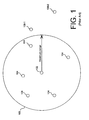
- FIG. 1 shows a two-dimensional layout of a group of nodes in a prior art TDMA based mobile ad hoc network (MANET).
- the transmitting node is node 102.
- the system has a guard time that is designed to accommodate maximum range indicated by the radius of the circle 103.
- Nodes 104 are within this radius.
- Node 106-1 is outside this radius.
- Node 106-2 is further outside the radius as compared to node 106-1.
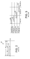
- the time slot has a duration 201, a maximum RF burst time 202, and a guard time 203.
- the guard time is provided to accommodate range uncertainty as well as other timing uncertainties at the receiver and transmitter.
- An RF burst 206 is shown within the maximum burst time 202.
- FIG. 1 it can be understood that transmissions from node 102 to node 106-1 or 106-2, which are of the maximum RF burst length, will contaminate the following (or later) time slot for node 106-1, 106-2 because these nodes are each located beyond the radius of the maximum range circle 103.
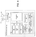
- the transmit RF burst 206 of maximum length is shown in time slot n.
- the RF burst 206 arrives within slot n because node 104 is within the maximum guard time protected range.
- RF burst 206 is received at a node 106-1 (beyond maximum protected range) the transmission will cause interference for node 106-1 in time slot n+1.
- the transmission will cause interference in time slot node n+2.
- transmitted RF bursts 206 that are not of maximum length may or may not contaminate the following time slot(s).
- the length of the guard period 203 can be defined so that it comprises a greater portion of the total time 201 comprising time slot 200. Increasing the length of time of the guard period in this way can allow more distant nodes, such as nodes 106-1, 106-2 to receive the RF burst 206 within the guard period for a time slot n. Thus, if it is known that the network must cover a larger area, a longer guard period can be selected. However, it will be appreciated that increasing the guard period in this way will decrease the time available for the RF burst 206. This has the undesirable effect of reducing efficiency.
- FIGS. 4-15 in which illustrative embodiments of the invention are shown. This invention, may however, be embodied in many different forms and should not be construed as limited to the embodiments set forth herein.
- an embodiment of the invention includes a peer-to-peer TDMA type mobile ad hoc network comprised of a plurality of individual nodes.
- the individual nodes communicate with each other within an ad-hoc network environment.
- information concerning the range between node pairs is estimated and exploited. Consequently, the scalability, latency, and efficiency of the TDMA communication system can be significantly enhanced.
- the inventive arrangements advantageously include a distributed long range scheduler function as part of each node.
- the distributed long range scheduler determines specific times when node pairs can communicate so as to avoid interfering with one another. Heuristics produce an efficient distributed schedule for communication between node pairs.
- This schedule is advantageously based on information which includes both node range and angle (i.e. direction).
- Accurate time references are provided at each node and nodes exchange position estimates so that each node can maintain an estimate of range to its various neighbors. Further, unlike conventional arrangements which provide a time axis measured in fixed time slots per epoch, the inventive arrangements make use of a plurality of mini-slots.
- a plurality of mini-slots can be arbitrarily selected to define a time slot which is thereafter used for communications from one node to another node.
- the time slot is independently evaluated by each node to determine whether its use will cause interference with neighboring nodes.
- Each node independently adjusts its schedule to account for the link delay. Further, transmit and receive time slots are scheduled separately to allow for more efficient use of available time.
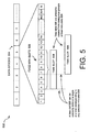
- the wireless mobile node can be used in a wireless communication network as described herein.
- the wireless mobile node 404 is comprised of a directional antenna 404, a transceiver 406, and a control unit 408.
- the wireless mobile node 404 can optionally include an omni-directional antenna 402.
- the transceiver 406, the omni-directional antenna 402 and the phased array antenna 404 collectively enable wireless communications between the wireless mobile node 404 and a plurality of other nodes having a similar configuration in the .
- the omni-directional antenna 402 is configured to send and/or receive signals in any direction.
- the directional antenna 404 is configured to selectively send and/or receive signals in a desired direction.
- the directional antenna 404 can include, but is not limited to, a phased array antenna.
- the omni-directional antenna 402 and directional antenna 404 are coupled to the transceiver 406 so that RF signals can be communicated to and from each of these antennas.
- the omni-directional antenna can be omitted and omni-directional communications can be provided by scanning a directional antenna beam through a wide range of azimuth and elevation angles.
- the transceiver 406 can include conventional RF circuitry (not shown) and a modem (not shown) for receiving and transmitting RF signals.
- the transceiver 406 is electrically connected to the controller 450 so that received signals demodulated by the transceiver 406 can be communicated to the control unit 408. Similarly, baseband digital data and control signals can be communicated from the control unit 408 to the transceiver 406.
- the control unit 408 is comprised of processor 410, antenna control unit 412, a clock 414, and node position unit 416.
- the antenna control unit 412 can control a direction of an antenna beam associated with the directional antenna 404.
- the antenna control unit 412 can optionally be included as part of the transceiver 406.
- Clock 414 provides a highly accurate and stable time reference for each node. The accuracy of the clock 414 can be maintained by any suitable means. For example, a GPS timing signal can be used for this purpose. As will be appreciated by those skilled in the art, GPS timing signals can provide a highly accurate time reference.
- clock 414 can be synchronized with clocks of other wireless mobile nodes forming part of the network described herein.
- the clocks are preferably synchronized to within a fractional portion of a mini time-slot (described below in greater detail).
- the time references can advantageously be selected so that a clock 414 associated with each node 404 is synchronized to within 100 nanoseconds of other nodes in the network. Still, the invention is not limited in this regard.
- the control unit 408 also includes a node position unit.
- the node position unit is configured to allow the node to identify its position.
- the node position unit can advantageously include a GPS receiver and GPS processing circuitry suitable for allowing the node 404 to precisely locate its position at any terrestrial or airborne location. If a GPS receiver is used, the GPS timing data can be used as described above to aid in synchronizing the clocks 414 in each of the nodes 404.
- the control unit 408 also includes a memory device 450.
- the memory device 450 stores several different types of information.
- the memory device 450 can includes a neighbor information table 420, epoch schedule 422, a receive (Rx) interference profile 424, a transmit (Tx) interference profile 426, and a neighbor time-slot usage profile 428.
- the various types of information stored in memory device 450 will be discussed below in greater detail.
- the various components forming the control unit 408 can communicate with each other by means of a suitable data bus 418.
- wireless mobile node 404 is one possible example of a wireless mobile node which can be used with the present invention. However, it should be understood that the invention is not limited in this regard. Instead, any other suitable wireless mobile node architecture can also be used without limitation.
- individual network nodes 404 use a neighbor discovery process.
- the neighbor discovery process includes an exchange of position information so that each node has the coordinates of neighboring nodes. This position information allows the range information and relative direction of such neighbor nodes to be calculated. Range information and direction information is used for purposes of performing interference calculations. Interference calculations also include consideration of propagation delays between nodes and required antenna beam pointing directions based on the known node locations.
- the present invention is unlike conventional MANET systems that utilize conventional TDMA technology.
- periods of time are divided into epochs, and communication between nodes occurs in time slots which are sub-portions of each epoch.
- time slots which are sub-portions of each epoch.
- each time slot in a conventional system will have a fixed timing position in each epoch. Nodes in the ad hoc network which need to communicate are assigned time slots for such communications. However, this fixed timing creates problems for long range communications.
- the present invention also divides time into a series of epochs.
- the timing of the time slots used for communications between nodes is not fixed. State differently, it can be said that the timing position of each time slot is not fixed within each epoch.
- the position of time slots within each epoch can be arbitrarily selected by the nodes in accordance with an algorithm. The algorithm is selected for minimizing potential interference among neighbor nodes.
- each mini-time slot can have a duration which is 1/8 of the duration of a time slot.
- FIG. 5 there is shown a timing diagram 500 for a TDMA type mobile ad hoc network according to the inventive arrangements.
- the timing diagram shows a series of data epochs 504 which are fixed divisions of time.
- Each epoch 504 is sub-divided into a plurality of N mini-slots 506.
- a time slot 508 can be comprised of contiguous groups of M mini-slots.
- Each time slot 508 can have an arbitrarily defined starting position (subject to interference calculations) that corresponds to a starting time of any selected mini-slot.
- the transmit beam pattern 602 is shown for node 2.
- Nodes 404 4 , 404 6 , 404 7 and 404 9 are located within range and in the beam pattern.
- a time slot scheduler can be used to automatically select a timing position for a transmit time slot that will minimize interference to neighboring nodes.
- the scheduler process begins by selecting a candidate set of mini-slots which will define the position of the transmit time slot for node 404 2 .
- FIG. 7 is a timing diagram 700 which shows the time base at nodes 404 2 , 404 4 , 404 6 , 404 7 and 404 9 . It is assumed that clocks 414 at the nodes 404 1 - 404 9 are synchronized to fractions of a mini-slot.
- the timing diagram shows that a candidate set of mini-slots MT 2 - MT 6 can be selected at node 404 2 which define a possible timing position for time slot 702.
- the timing position of time slot 702 is mapped to the corresponding time intervals at nodes 404 4 , 404 6 , 404 7 and 404 9 .
- These corresponding time intervals 704, 706, 707, 709 are offset from time slot 702 because of the propagation delay "d" between the nodes.
- Propagation delay can be determined if the transmitting node 404 2 knows the relative position of neighbor nodes 404 6 , 404 7 and 404 9 .
- the corresponding time interval for the receiver node 404 4 is 704.
- the corresponding time intervals mapped to the location of nodes 404 6 , 404 7 and 404 9 are respectively 706, 707, 709.
- Time intervals 706, 707, 709 represent the time intervals at nodes 404 6 , 404 7 and 404 9 during which the signal will arrive from node 404 2 if transmitted during time slot 702.
- transmitting node 404 2 can be within a receive antenna beam 606 of node 404 6 during a transmit time interval.
- transmitting node 404 2 can advantageously be provided with position and timing schedule for neighbor nodes to determine the direction in which its neighbor node antennas are pointing during each mini-slot.
- transmitting node 404 2 determines that any one of nodes 404 6 , 404 7 and 404 9 are in fact scheduled to receive signals (1) from a direction which coincides with transmitting node 404 2 , and (2) such signals are scheduled to be received during the intervals 706, 707, 709, then it can conclude that the transmissions from node 404 2 during time slot 702 will cause interference. If transmitting node determines that interference will occur, then a different candidate time slot 702 is advantageously selected.
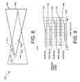
- FIG. 8 shows a planar geometry 800 which is similar to the one shown in FIG. 6 . However, in FIG. 8 , nodes 404 6 , 404 7 and 404 9 are omitted for greater clarity since they are not part of this analysis. It can be observed in FIG. 8 that nodes 404 1 , 404 2 , 404 3 and 404 5 are located within the range and in the receiver beam pattern 812 of node 404 4 .
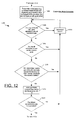
- FIG. 9 shows a timing diagram which includes segment of the time base at several nodes 404 1 - 404 5 . It is assumed that clocks 414 at the nodes 404 1 - 404 4 are synchronized to fractions of a mini-slot. In FIG. 9 , the timing position of time interval 704 is mapped to the corresponding time intervals at nodes 404 1 , 404 3 , and 404 5 . These corresponding time intervals 901, 903, 905 are offset from time slot 704 because of the propagation delay "d" between the nodes.
- FIG. 9 shows a timing diagram which includes segment of the time base at several nodes 404 1 - 404 5 . It is assumed that clocks 414 at the nodes 404 1 - 404 4 are synchronized to fractions of a mini-slot.
- the timing position of time interval 704 is mapped to the corresponding time intervals at nodes 404 1 , 404 3 , and 404 5 .
- node 404 4 will experience interference during time interval 704 if nodes 404 1 , 404 3 , or 404 5 transmit toward node 404 4 during time periods 901, 903, or 905. If node 404 4 has transmission schedules and position information for nodes 404 1 , 404 3 , or 404 5 then it can determine whether time interval 704 is an acceptable receive time for node 404 4 . In the same way, node 404 4 can determine whether time interval 702 is an acceptable transmit time slot for node 404 2 .
- FIG. 10 provides a basic overview of a mobile ad hoc network process 1000. It will be understood that the scheduler process described in relation to FIGS. 6-9 requires detailed information regarding the identification, position, and communication schedule of neighbor nodes. Process 1000 is useful for understanding how such information is exchanged. Still, it should be understood that the process 1000 merely discloses one possible process for exchange of such data and the invention is not intended to be so limited. Instead, any other process for exchanging node identification, position, and communication schedule can be used. Further, it should be understood that all of the foregoing information can be exchanged using one or more control channels. For example, one or more mini-slots can be defined as control channels which are reserved for exchange of such information.
- the process 1000 begins in step 1002 and continues with step 1004.
- nodes in a network engage in a neighbor discovery process.
- Neighbor discovery processes in mobile ad hoc networks are generally well known. Accordingly, the details of this process will not be described here.
- the neighbor discovery process involves transmission of "hello" messages to neighboring nodes using a control channel.
- the "hello" message can be broadcast to neighboring nodes by any suitable means.
- the "hello” message can be transmitted by using an omni-directional antenna 402 or a scanned beam provided by directional antenna 404.
- the "hello" message can include node identifier information and a position report for the node which transmits the message. Each node determines its own position using the node position unit 416. Each node also collects identifying information and position information from its neighbors using these "hello" messages.
- step 1006 information derived from the neighbor discovery process in step 1004 is used to populate (and/or update) neighbor information tables at each node.
- node identification and position information can be stored in a neighbor information table 420.
- Each node further maintains an epoch schedule 422 which provides timing information for the occurrence of each data epoch 504. Timing of mini-slots 506 can also be derived from the epoch schedule 422.
- each node periodically communicates to its neighbors a transmit schedule for that node.
- each node also periodically broadcasts to its neighbors a receive schedule for that node.
- each node stores neighbor transmit and receive information in the table in FIG. 4 identified as the neighbor time slot usage profile 428.
- each node uses processor 410 to apply topology control rules to the information stored in its neighbor information table 420.
- the topology control rules can be stored in memory device 450.
- the topology control rules are used to select one or more neighbor nodes with which communication links should be established. Topology control rules for mobile ad hoc networks are well known in the art and therefore will not be described here in detail. However, it should be understood that such topology control rules can allow a node to determine whether communication links with various neighbor nodes should be established, maintained, or terminated.
- new communication links are formed with selected neighboring nodes as determined by the topology control rules. This process of forming links with new nodes will be described in more detail in relation to FIGS. 11-14 .
- step 1018 certain communication links are terminated with selected neighbor nodes as determined by topology control rules.
- step 1020 a determination is made as to whether the network process should be terminated for any reason. If so, then the process terminates in step 1022. Alternatively, the process continues with step 1004 and repeats.
- FIG. 11 shows a series of steps which provide further detail concerning step 1016 in FIG. 10 .
- Step 1016 involves one node forming a communication link with a selected neighbor node. Establishing this communication link begins with selection of a suitable time slot when a first node (transmitter node) will transmit data to a second node (receiver node).
- step 1016 includes a series of steps which can begin with step 1102.
- Step 1102 includes using a scheduler process at the transmitter node to generate a list of candidate transmit time slots for transmissions from the transmitter node to the receiver node.
- the scheduler process can be performed by processor 410 executing a programmed set of instructions. Alternatively, the scheduler process can be implemented as any other combination of hardware and software.
- Step 1102 is described in greater detail in FIG. 12 .
- the list of candidate time slots can be generated using an interference analysis similar to that described in relation to FIGS. 6-7 . In this regard it may be noted that in FIGS. 6 and 7 the transmitter node was node 404 2 and the receiver node was 404 4 .
- the list of candidate transmit time slots can be communicated from the transmitter node to the receiver node.
- Any suitable means can be used for communicating this candidate transmit time slot list from the transmitter node to the receiver node.
- a dedicated control channel can be used for this purpose. Still, the invention is not limited in this regard.
- step 1106 the candidate transmit time slot list is received and used at the receiver node to determine which of the proposed candidate time slots are acceptable.
- Step 1106 is described in greater detail in FIG. 13 .
- acceptable candidate time slots can be determined using a process similar to that previously described in relation to FIGS. 8-9 .
- the receiver node will now be aware that transmitter node wishes to establish a transmit time slot for communications to receiver node. Consequently, the receiver node can initiate another process similar to that described in step 1016 for the purpose of establishing a transmit time slot for communications from the receiver node to the transmitter node. To avoid redundancy, that process will not be described here.
- a message can be sent from the receiver node to the transmitter node.
- the message identifies those transmit time slots proposed by the transmitter node which are determined to be acceptable to the receiver node.
- this message is received at transmitter node.
- the process continues on to step 1112 in which the receiver node begins listening for transmissions from the transmitter node during the time slot which has been accepted by the transmitter node.
- step 1114 data transmissions can begin from the transmitter node to the receiver node using the time slot that has been selected. Thereafter, the process can continue on to step 1018 as previously described.
- Step 1102 involves using a scheduler process at the transmitter node to generate a list of candidate transmit time slots for transmissions from the transmitter node to the receiver node. As an aid to understanding, step 1102 will be described with reference to FIG. 5 .
- the process can begin with step 1202 in which the scheduler process at the transmitter node selects a candidate transmit time slot beginning at mini-slot n and comprised of M mini-slots that are contiguous with each other.
- the scheduler process checks the transmitter node's transmit and receive schedule to determine whether any of the M mini-slots comprising the candidate time slot is already in use at the transmit node (for receiving or transmitting).
- the transmitter node's transmit and receive schedule can be stored in memory 450.
- step 1206 the value of n is incremented and the step 1204 is repeated with a different set of M mini-slots.
- the value of n can be incremented by 1.
- the invention is not limited in this regard.
- the value of n could be incremented by M or any other value.
- step 1204 if none of the M mini-slots are currently in use at the transmitter node, then the process continues on to step 1208.
- step 1208 the scheduler process determines whether any of the M mini-slots are in use at the receiver node. Information concerning time slot usage at the receive node can be obtained from the neighbor time slot usage profile 428 which is stored in memory device 450. If any of the time slots are currently in use at the receiver node, the process can return to step 1206 where the value of n is incremented to select a different set of M mini-slots. Alternatively, if the M mini-slots are not in use at the receiver node, then the process continues on to step 1210.
- step 1210 the scheduler process in the transmitter node determines whether the transmitter node's use of the M mini-slots associated will cause interference to neighboring nodes located in the transmit beam of the transmitter node (when pointed toward the receiver node). This process for mitigating interference is described below in more detail in relation to FIG. 14 . If the scheduler process determines that use of the M mini-slots by the transmitter node will cause interference to neighboring nodes, then the process returns to step 1206 and an alternative set of mini-slots is selected for evaluation. Conversely, if the scheduler process determines that use of the M mini-slots by the transmitter node will not cause interference to neighboring nodes, then the process continues on to step 1212.
- step 1212 the candidate time slot comprised of the M mini-slots is added to a list of candidate time slots which can be used. Thereafter, in step 1214, a determination is made as to whether the candidate transmit time slot list is complete. This determination can be based on any one of several considerations. For example, the list can be deemed complete when a predetermined number of candidate transmit time slots have been identified. Alternatively, the list can be complete when all possible candidate time slots have been considered.
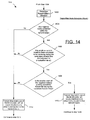
- step 1210 generally involves a scheduler process at the transmitter node.
- the scheduler process is used to evaluate potential interference caused by the transmitting node's use of the M mini-slots associated with the candidate time slot.
- this scheduler process determines whether the transmissions by the transmitter node during the candidate time slot, using an antenna beam pointing toward the receiver node, will cause interference to other neighboring nodes that are also located in the transmit beam.
- the process will be described with reference to FIGS. 6 and 7 in which node 404 2 is considered the transmitter node and node 404 4 is considered to be the receiver node.
- step 1402 the transmitter scheduler at the transmitter node determines a direction that it's transmit beam will be pointed for the purpose of communicating with the receiver node.
- the scheduler process at the transmitter node (404 2 ) will determine in step 1404 whether there are any neighbor nodes that are contained within the transmit beam. If not, then it can be assumed that the transmitter node's use of the M mini-slots will not cause interference to any other nodes and the process will continue on to step 1412.
- step 1404 determines whether there are neighbor nodes contained within the transmit beam. For example, in FIG. 6 nodes 404 6 , 404 7 , 404 9 are in the transmit beam 602 (in addition to node 404 4 ).
- step 1406 the scheduler process determines whether there are any neighbor nodes in the transmit beam that are scheduled to be receiving during the candidate transmit time slot as adjusted for propagation delay. This concept is illustrated in FIG. 7 .
- the transmitter scheduler would determine whether any of the nodes 404 6 , 404 7 , 404 9 are scheduled to be receiving during time intervals 706, 707, 709. If not, then it can be assumed that no interference will occur and the scheduler process continues on to step 1412. Otherwise, the scheduler process goes on to step 1408.
- step 1408 a determination is made as to whether any of the receive beam of the neighbor nodes is pointing toward the transmitter during the candidate transmit time (adjusted for propagation delay). In the context of FIG. 7 , this would mean determining whether the antenna beams of any of the nodes 404 6 , 404 7 , 404 9 are pointing toward the transmitter node 404 2 . In FIG. 6 , it can be observed that antenna beam 606 of node 404 6 is pointing toward the transmitter node 404 2 during time interval 706. In this example, the scheduler process would continue on to step 1410 and determine that the transmitter node's use of the M mini-slots associated with a particular candidate time slot will cause interference to the other nodes located in the transmit beam.
- step 1412 determines that the transmitter node's use of the M mini-slots will not cause interference. From step 1412, the process continues on to step 1212 where the candidate time slot is added to the candidate time slot list.
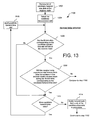
- step 1102 the scheduling process at the receiver determines which, if any, of the candidate time slots are acceptable. Step 1106 will now be described in further detail with reference to FIG. 13 .
- the process can begin in step 1302 when the receiver scheduler receives the list of candidate transmit time slots at the receiver node.
- step 1304 the receiver scheduler selects the first candidate time slot on the list for evaluation.
- step 1306 The evaluation process begins in step 1306 with the receiver scheduler process at the receiver node determining whether the M mini-slots corresponding to the candidate transmit time slot are still idle and are therefore available. This step is somewhat redundant because a similar check is performed in step 1208. However, it will be appreciated that the transmit and receive schedule at the receiver node will often contain scheduling information for the receiver mode that is more current than the corresponding information for the receiver node that is stored in at the transmitter node. Accordingly, step 1306 is a useful verification that the M mini-slots are still idle.
- step 1312 the receiver scheduler process determines whether there are any more candidate transmit time slots on the candidate transmit time slot list.
- step 1306 if the M mini-slots associated with a candidate time slot are in fact available, then the process continues on to step 1308.
- step 1308 the receiver scheduler process at the receiver node determines whether the receiver node will experience interference from network nodes other than the transmitter node.
- Step 1308 is described in greater detail in relation to FIG.15 . However, it should be understood that the receiver scheduler process in step 1308 determines whether the receiver node will experience interference from other neighboring nodes during the M mini-slots corresponding to the candidate transmit time slot (as adjusted in time to compensate for propagation delay). If, in step 1308, the receiver scheduler process determines that no interference will result from neighboring nodes, then the process continues on to step 1108 in FIG. 11 . In step 1108, a message is sent to the transmitter node indicating that the candidate time slot is acceptable to the receiver node. Alternatively, if the receiver scheduler process determines that the receiver node will experience interference from other neighboring nodes, then the process continues on to step 1312.
- step 1312 the receiver scheduler process determines whether there are any other candidate time slots on the candidate time slot list. If so, then the receiver scheduler process continues on to step 1316 where the next candidate time slot is selected. Alternatively, if there are no more candidate time slots on the list, the receiver scheduler process continues on to step 1314 in which the receiver node notifies the transmitter node that none of the candidate time slots are acceptable. The receiver scheduler process then returns to step 1102 in FIG. 11 , where a new list of candidate time slots is generated at the transmitter node.
- step 1502 the scheduler process at the receiver node determines a direction that it's receive beam will be pointed for the purpose of receiving communications from the transmitter node.
- the scheduler process at the receiver node (404 4 ) will determine in step 1504 whether there are any neighbor nodes that are contained within the receiver antenna beam 812.
- step 1504 If it is determined in step 1504 that there are no neighbor nodes contained within the receiver antenna beam 812, then the process continues in step 1512.
- step 1512 the scheduler process determines that the receiver node 404 4 will not experience interference from other transmitting nodes during the time interval corresponding to the M mini-slots (as adjusted for propagation delay). Accordingly, the process will thereafter continue on to step 1108 in FIG. 11 .
- step 1504 if it is determined in step 1504 that there are neighbor nodes contained within the receiver antenna beam 812, then the process continues on to step 1506. For example, in FIG. 8 nodes 404 1 , 404 3 , 404 5 are in the receiver antenna beam 812 (in addition to node 404 2 ). Accordingly, the process would continue on to step 1506 in the example shown in FIG. 8 .
- step 1506 the scheduler process at the receiver node determines whether transmitted signals from any neighbor nodes in the receiver beam 812 can potentially be received at the receiver node 404 4 during any of the mini-slots corresponding to the time interval 704.
- time interval 704 is the period of time during which a transmission from transmitter node 404 2 will actually be received at receiver node 404 4 (assuming that the signal is transmitted from node 404 2 during time slot 702).
- time intervals 901, 903, 905 represent those transmission time intervals for nodes 404 1 , 404 3 , 404 5 that will result in signals actually being received at receiver node 404 4 during time interval 704.
- step 1506 if none of the nodes 404 1 , 404 3 , 404 5 are actually scheduled to be transmitting during the time periods 901, 903, 905, then it can be concluded that no interference will be caused at the receiver node 404 4 during time interval 704. In that case, the transmit time slot 702 would be an acceptable time slot during which node 404 2 can transmit to node 404 4 , and the scheduler process continues on to step 1512. Conversely, if any of the nodes 404 1 , 404 3 , 404 5 are actually scheduled to be transmitting during the time periods 901, 903, 905, then such transmissions can potentially cause interference at the receiver node 404 4 during time interval 704. In that case, the transmit time slot 702 may not be an acceptable time slot during which node 404 2 can transmit to node 404 4 . Accordingly, the scheduler process will continue on to step 1508.
- step 1508 a determination is made as to whether an antenna beam of any neighbor nodes that is actually pointed toward the receiver 404 4 during a time interval when the receiver is expecting to receive signals from the transmitter node. In the context of FIG. 9 , this would mean determining whether the antenna beams of any of the nodes 404 1 , 404 3 , 404 5 are pointing toward the receiver node 404 4 during time intervals 901, 903, 905. If so, then the scheduler continues on to step 1510 where it determines that other transmitters will cause interference to the receiver if the transmitter node uses the M mini-slots associated with a candidate transmit time slot such as slot 702. Following step 1510, the scheduler process at the receiver node continues on to step 1312 in FIG. 13 . In step 1312 the scheduler process checks to see if other candidate time slots are available and continues on as described above.
Abstract
Description
- The inventive arrangements relate to directional networks that can cover terrestrial and airborne nodes over hundreds of nautical miles, and more particularly to long range TDMA time slot scheduling in peer-to-peer directional networks.
- Peer-to-peer mobile ad hoc networks (MANET) using directional antennas are known in the art. These MANET networks can use a variety of communications formats including Time Division Multiplexed Access (TDMA) arrangements. Further, they are characterized by independence from fixed infrastructures and by peer-to-peer distributed control mechanisms and protocols. In TDMA type MANET networks, each node can communicate during a specified time period or time slot. In order to coordinate such communications, each node can include a clock which is synchronized with a highly stable time reference. For example, this stable time reference can be derived from a satellite-based GPS signal. It should be noted that TDMA cellular systems often rely on synchronization to base stations to establish system timing and to compensate for propagation delay differences. Such TDMA cellular systems include, but are not limited to, global systems for mobile communications (GSM), Integrated Digital Enhanced Network (iDENs) systems, 802.16 based broadband wireless access network systems, and TDMA satellite communications (SATCOM) systems.
- Still, each TDMA node can be expected to have a significant total time base uncertainty. Also, propagation delay between nodes can create additional timing uncertainties that change in real time as the mobile nodes move relative to one another. In order to manage these timing uncertainties, prior art systems use a base station infrastructure to create a hub and spoke typology. These base stations are usually, but not necessarily, fixed in location. The mobile nodes operate as "spokes" or "clients" to the basestation hubs and synchronize their transmissions to those base stations.
- A MANET is an infrastructureless network that uses peer-to-peer control mechanisms and therefore does not have base stations to provide a central timing reference. Therefore, there is a need in a TDMA MANET for a new time synchronization method that can compensate for variable propagation delay and other propagation uncertainty in the absence of a central infrastructure.
- In a TDMA MANTET, a transmitted RF burst is can be transmitted within a time slot as close to the beginning of the time slot as possible. The time slot length can be selected to exceed the maximum RF burst length by an amount of time referred to as the "guard time." This guard time is used to accommodate any timing uncertainties at either the transmitter or receiver, and the maximum propagation time delay. If the range delay between the transmit node and the receive node exceeds the allocation in the guard time, a maximum length RF burst will spill over into the following time slot at the receiver. This spillover can cause interference if such following time slot is in use for communications as between other nodes.
- Conventional MANET networks using TDMA generally choose a guard time which is based (at least in part) on the maximum permitted range between nodes. In this regard, networks which are designed to accommodate larger distances between nodes can require larger guard times. These larger guard times are necessary to accommodate potentially longer propagation delays between distant nodes. This approach can provide acceptable results for a limited network range. However, for networks operating over hundreds of nautical miles, the guard time can become relatively lengthy in duration. Such lengthy guard periods restrict the available time for other nodes to communicate with each other, leading to inefficiencies in the overall network. For example, a system which has 88% efficiency with an operating range of 11 nautical miles can have an efficiency of only 16% if the operating range is extended to 440 nautical miles.
- In order to address this problem, several existing TDMA wireless systems have used range adjusted timing systems. However, such systems have generally only been applied in hub-spoke type networks. The problem becomes more considerably more complex in the case of ad-hoc peer-to-peer networks. Accordingly, a new approach is needed for ad-hoc peer-to-peer communications networks to facilitate TDMA communications which are capable of providing efficient communications over larger geographic areas.
- The invention concerns a method and apparatus for scheduling time division multiple access (TDMA) communications among a plurality of nodes arranged to form a wireless ad hoc mobile network. The nodes communicate with each other using directional antennas and a TDMA scheduling process. The nodes have knowledge of the range between the transmitting node and other nodes within the radio line of sight of the transmitting node. The method includes a scheduling process for scheduling at least one transmit time slot during which a first one of the plurality of nodes transmits wireless data to a second one of the plurality of nodes. The scheduling process includes automatically selecting a candidate time slot for the transmit time slot. The scheduling process also includes determining whether transmissions during the candidate time slot will (1) cause interference with communications of any of the plurality of nodes that are located in a defined transmit antenna beam of the first node, or (2) be subject to interference when received at the second node as a result of transmissions from any of the plurality of nodes located in a defined receive antenna beam of the second node.
- A data epoch is defined for the TDMA process. The data epoch includes a recurring time period which defines an overall timing cycle for the TDMA process. Each data epoch is sub-divided in time to form a plurality of mini-slots, each comprising a fractional duration of the data epoch. The scheduling process includes selecting the candidate time slot to have a duration which includes a plurality of M contiguous mini-slots. The scheduling process further includes automatically selecting the candidate time slot to include any contiguous group of M mini-slots contained within the data epoch.
- The scheduling step further includes automatically selecting a receive time slot for the second node. The receive time slot length corresponds to the transmit time slot, but the arrival time is automatically adjusted in time to compensate for a propagation delay between the first node and the second node, which is directly known a priori or derived from prior knowledge of the range between the nodes. In this regard, the receive time slot can comprise a different contiguous group of mini-slots as compared to the transmit time slot. Significantly, the second node automatically determines the receive time slot exclusive of any centralized controller for the mobile ad hoc network. According to a preferred embodiment, the scheduling process is a distributed process which is cooperatively performed in a process which involves at least at the first node and the second node.
- The scheduling step further includes automatically selecting an alternative candidate time slot. For example, the alternative candidate time slot will be selected if it is determined that transmissions from the first node to the second node during the initially selected candidate time slot will (1) cause interference with communications of any of the plurality of nodes that are located in the defined transmit antenna beam of the first node, or (2) be subject to interference when received at the second node as a result of transmissions from any of the plurality of nodes located in the defined receive antenna beam of the second node.
- The method also includes a second scheduling step. The second scheduling step involves scheduling at least a second transmit time slot during which the second one of the plurality of nodes to transmit wireless data to the first one of the plurality of nodes. The second scheduling step also makes use of a distributed scheduling process. The second scheduling step includes automatically selecting a second candidate time slot for the second transmit time slot and determining whether transmissions during the second candidate time slot will (1) cause interference with communications of any of the plurality of nodes that are located within the radio line of sight of the second node, or (2) be subject to interference when received at the first node as a result of transmissions from any of the plurality of nodes located in a defined receive antenna beam of the first node. If the nodes use directional antennas, then this step includes a consideration of the antenna pattern and beam location when the potential to cause interference is evaluated.
- The inventive arrangements also include an alternative method for scheduling time division multiple access (TDMA) communications among a plurality of nodes using directional antennas in a mobile ad hoc network. The alternative method includes arranging a plurality of nodes to form a wireless ad hoc mobile network. The nodes communicate with each other using directional antennas and a TDMA process. The method includes using a peer-to-peer distributed scheduling process. The distributed scheduling process includes automatically scheduling for each node at least one transmit time slot for transmitting wireless data to a neighboring one of the plurality of nodes. The method also includes automatically scheduling for each node a receive time slot for receiving signals transmitted from a neighboring one of the plurality of nodes during a respective one of the transmit time slots. Significantly, each of the receive time slots corresponds to a time of a respective one of the transmit time slots, but is automatically adjusted delayed in time to compensate for a propagation delay between nodes.
- The scheduling step further includes automatically selecting at each node a candidate time slot for the transmit time slot and determining whether transmissions during the candidate time slot will (1) cause interference with communications of any of the plurality of nodes that are located in a defined transmit antenna beam of the node, or (2) be subject to interference when received at the neighboring node resulting from transmissions from any of the plurality of nodes located in a defined receive antenna beam of the neighboring node.
- In the alternative embodiment, a data epoch is defined for the TDMA process. The data epoch includes a recurring time period which defines an overall timing cycle for the TDMA system. Each data epoch is sub-divided in time to form a plurality of mini-slots, each comprising a fractional duration of the data epoch. Significantly, the transmit time slot is selected to have a duration which includes a plurality of M contiguous mini-slots. The scheduling process further includes automatically selecting the transmit time slot to include any contiguous group of M mini-slots contained within the data epoch.
- According to yet another embodiment, the invention includes a distributed system for scheduling time division multiple access (TDMA) communications among a plurality of nodes using any combination of omni or directional antennas in a mobile ad hoc network. The system includes a plurality of nodes arranged to form a wireless ad hoc mobile network that communicate with each other using directional antennas and a TDMA process. A processor for performing scheduling functions is provided at each node. The processor at each node cooperates with processors at other nodes to cooperatively schedule at least one transmit time slot during which a first one of the plurality of nodes transmits wireless data to a second one of the plurality of nodes. The processor is further configured to automatically select a candidate time slot for the transmit time slot. The processor cooperates with at least one other processor in another node to determine whether transmissions during the candidate time slot will (1) cause interference with communications of any of the plurality of nodes that are located in a defined transmit antenna beam of the first node, or (2) be subject to interference when received at the second node resulting from transmissions from any of the plurality of nodes located in a defined receive antenna beam of the second node.
- The TDMA process includes a data epoch comprising a recurring time period which defines an overall timing cycle for the TDMA process. Each data epoch is sub-divided in time to form a plurality of mini-slots, each comprising a fractional duration of the data epoch. The processor in each node that is used for scheduling processing is configured for selecting the candidate time slot to have a duration which includes a plurality of M mini-slots. Notably, the processor is configured to automatically select the candidate time slot to include any contiguous group of M mini-slots contained within the data epoch.
- The processor at each node is also configured to automatically select a receive time slot for the second node corresponding to a time of the transmit time slot, wherein the receive time slot is automatically adjusted in time to compensate for a propagation delay between the first node and the second node. Significantly, the processor used for scheduling at the second node automatically determines the receive time slot exclusive of any centralized controller for the mobile ad hoc network. The receive time slot includes a different contiguous group of mini-slots as compared to the transmit time slot.
- The TDMA process includes a "neighbor database" at each node that maintains knowledge of the location of or equivalently the relative range and angles between the plurality of nodes within the radio line of sight of the first node. The neighbor database also includes knowledge of the currently scheduled transmit and receive timeslots at the plurality of nodes included in the neighbor database.
- The TDMA process includes a method for populating the database of node locations of the plurality of nodes. Those skilled in the art will appreciate that there are numerous methods available to populate a database with this information. The methods include broadcast or multicast transmissions between the nodes or downloads from an external source.
-
FIG. 1 is a drawing that is useful for understanding timing problems which occur in mobile ad hoc networks. -
FIG. 2 is a timing diagram that is useful for understanding timing problems which occur in mobile ad hoc networks. -
FIG. 3 is a timing diagram that is useful for understanding timing problems which occur in mobile ad hoc networks. -
FIG. 4 is a block diagram of a wireless mobile node that can be used to implement the present invention. -
FIG. 5 is a timing diagram that is useful for understanding a timing relation between data epochs, mini-slots, and time slots. -
FIG. 6 is a drawing that shows a planar geometry of several nodes which is useful for understanding the invention. -
FIG. 7 is a timing diagram that is useful for understanding potential sources of interference inFIG. 6 . -
FIG. 8 is a drawing that shows the planar geometry of several nodes inFIG. 6 with different antenna pattern overlays. -
FIG. 9 is a timing diagram that is useful for understanding potential sources of interference inFIG. 8 . -
FIG. 10 is a flowchart that is useful for understanding an interaction among various nodes in a mobile ad hoc network. -
FIG. 11 is a flowchart that provides additional detail relating to step 1016 inFIG. 10 . -
FIG. 12 is a flowchart that provides additional detail relating to step 1102 inFIG. 11 . -
FIG. 13 is a flowchart that provides additional detail relating to step 1106 inFIG. 11 . -
FIG. 14 is a flowchart that provides additional detail relating to step 1210 inFIG. 12 . -
FIG. 15 is a flowchart that provides additional detail relating to step 1308 inFIG. 13 . - Conventional approaches to peer-to-peer, ad-hoc TDMA communication networks are based on knowing only the maximum range between nodes. This concept is illustrated in
FIGS. 1-3 .FIG. 1 shows a two-dimensional layout of a group of nodes in a prior art TDMA based mobile ad hoc network (MANET). InFIG. 1 , the transmitting node isnode 102. In this example, the system has a guard time that is designed to accommodate maximum range indicated by the radius of thecircle 103.Nodes 104 are within this radius. Node 106-1 is outside this radius. Node 106-2 is further outside the radius as compared to node 106-1. - Referring now to
Figure 2 there is shown aconventional time slot 200. The time slot has aduration 201, a maximum RF bursttime 202, and aguard time 203. The guard time is provided to accommodate range uncertainty as well as other timing uncertainties at the receiver and transmitter. An RF burst 206 is shown within the maximum bursttime 202. Referring again toFIG. 1 , it can be understood that transmissions fromnode 102 to node 106-1 or 106-2, which are of the maximum RF burst length, will contaminate the following (or later) time slot for node 106-1, 106-2 because these nodes are each located beyond the radius of themaximum range circle 103. - An alternative illustration of the foregoing concept is provided in
Figure 3 . The transmit RF burst 206 of maximum length is shown in time slot n. At anode 104 the RF burst 206 arrives within slot n becausenode 104 is within the maximum guard time protected range. When RF burst 206 is received at a node 106-1 (beyond maximum protected range) the transmission will cause interference for node 106-1 in timeslot n+ 1. At a more distant node 106-2, the transmission will cause interference in time slotnode n+ 2. As will be appreciated by those skilled in the art, transmitted RF bursts 206 that are not of maximum length may or may not contaminate the following time slot(s). - In
FIGS. 1-3 , the length of theguard period 203 can be defined so that it comprises a greater portion of thetotal time 201 comprisingtime slot 200. Increasing the length of time of the guard period in this way can allow more distant nodes, such as nodes 106-1, 106-2 to receive the RF burst 206 within the guard period for a time slot n. Thus, if it is known that the network must cover a larger area, a longer guard period can be selected. However, it will be appreciated that increasing the guard period in this way will decrease the time available for the RF burst 206. This has the undesirable effect of reducing efficiency. - The invention will now be described more fully hereinafter with reference to accompanying drawing
FIGS. 4-15 , in which illustrative embodiments of the invention are shown. This invention, may however, be embodied in many different forms and should not be construed as limited to the embodiments set forth herein. - In order to overcome the deficiencies of the prior art, an embodiment of the invention includes a peer-to-peer TDMA type mobile ad hoc network comprised of a plurality of individual nodes. The individual nodes communicate with each other within an ad-hoc network environment. Significantly, information concerning the range between node pairs is estimated and exploited. Consequently, the scalability, latency, and efficiency of the TDMA communication system can be significantly enhanced.
- The inventive arrangements advantageously include a distributed long range scheduler function as part of each node. The distributed long range scheduler determines specific times when node pairs can communicate so as to avoid interfering with one another. Heuristics produce an efficient distributed schedule for communication between node pairs. This schedule is advantageously based on information which includes both node range and angle (i.e. direction). Accurate time references are provided at each node and nodes exchange position estimates so that each node can maintain an estimate of range to its various neighbors. Further, unlike conventional arrangements which provide a time axis measured in fixed time slots per epoch, the inventive arrangements make use of a plurality of mini-slots. A plurality of mini-slots can be arbitrarily selected to define a time slot which is thereafter used for communications from one node to another node. The time slot is independently evaluated by each node to determine whether its use will cause interference with neighboring nodes. Each node independently adjusts its schedule to account for the link delay. Further, transmit and receive time slots are scheduled separately to allow for more efficient use of available time.
- Referring now to
FIG. 4 , there is provided a simplified block diagram for a wirelessmobile node 404 that is useful for understanding the present invention. The wireless mobile node can be used in a wireless communication network as described herein. The wirelessmobile node 404 is comprised of adirectional antenna 404, atransceiver 406, and acontrol unit 408. The wirelessmobile node 404 can optionally include an omni-directional antenna 402. - The
transceiver 406, the omni-directional antenna 402 and the phasedarray antenna 404 collectively enable wireless communications between the wirelessmobile node 404 and a plurality of other nodes having a similar configuration in the . In this regard, it should be appreciated that the omni-directional antenna 402 is configured to send and/or receive signals in any direction. Thedirectional antenna 404 is configured to selectively send and/or receive signals in a desired direction. Thedirectional antenna 404 can include, but is not limited to, a phased array antenna. The omni-directional antenna 402 anddirectional antenna 404 are coupled to thetransceiver 406 so that RF signals can be communicated to and from each of these antennas. In an alternative embodiment, the omni-directional antenna can be omitted and omni-directional communications can be provided by scanning a directional antenna beam through a wide range of azimuth and elevation angles. - The
transceiver 406 can include conventional RF circuitry (not shown) and a modem (not shown) for receiving and transmitting RF signals. Thetransceiver 406 is electrically connected to thecontroller 450 so that received signals demodulated by thetransceiver 406 can be communicated to thecontrol unit 408. Similarly, baseband digital data and control signals can be communicated from thecontrol unit 408 to thetransceiver 406. - The
control unit 408 is comprised ofprocessor 410, antenna control unit 412, aclock 414, andnode position unit 416. The antenna control unit 412 can control a direction of an antenna beam associated with thedirectional antenna 404. The antenna control unit 412 can optionally be included as part of thetransceiver 406.Clock 414 provides a highly accurate and stable time reference for each node. The accuracy of theclock 414 can be maintained by any suitable means. For example, a GPS timing signal can be used for this purpose. As will be appreciated by those skilled in the art, GPS timing signals can provide a highly accurate time reference. Thus,clock 414 can be synchronized with clocks of other wireless mobile nodes forming part of the network described herein. The clocks are preferably synchronized to within a fractional portion of a mini time-slot (described below in greater detail). According to one embodiment, the time references can advantageously be selected so that aclock 414 associated with eachnode 404 is synchronized to within 100 nanoseconds of other nodes in the network. Still, the invention is not limited in this regard. - The
control unit 408 also includes a node position unit. The node position unit is configured to allow the node to identify its position. For example, the node position unit can advantageously include a GPS receiver and GPS processing circuitry suitable for allowing thenode 404 to precisely locate its position at any terrestrial or airborne location. If a GPS receiver is used, the GPS timing data can be used as described above to aid in synchronizing theclocks 414 in each of thenodes 404. - The
control unit 408 also includes amemory device 450. Thememory device 450 stores several different types of information. For example, thememory device 450 can includes a neighbor information table 420,epoch schedule 422, a receive (Rx)interference profile 424, a transmit (Tx)interference profile 426, and a neighbor time-slot usage profile 428. The various types of information stored inmemory device 450 will be discussed below in greater detail. The various components forming thecontrol unit 408 can communicate with each other by means of asuitable data bus 418. - Those skilled in the art will appreciate that the architecture described herein for wireless
mobile node 404 is one possible example of a wireless mobile node which can be used with the present invention. However, it should be understood that the invention is not limited in this regard. Instead, any other suitable wireless mobile node architecture can also be used without limitation. - An overview of the basic operation of wireless mobile network utilizing a plurality of wireless
mobile nodes 404 according to the inventive arrangements will now be provided. According to an embodiment of the invention,individual network nodes 404 use a neighbor discovery process. The neighbor discovery process includes an exchange of position information so that each node has the coordinates of neighboring nodes. This position information allows the range information and relative direction of such neighbor nodes to be calculated. Range information and direction information is used for purposes of performing interference calculations. Interference calculations also include consideration of propagation delays between nodes and required antenna beam pointing directions based on the known node locations. - The present invention is unlike conventional MANET systems that utilize conventional TDMA technology. In such conventional TDMA systems, periods of time are divided into epochs, and communication between nodes occurs in time slots which are sub-portions of each epoch. Significantly, each time slot in a conventional system will have a fixed timing position in each epoch. Nodes in the ad hoc network which need to communicate are assigned time slots for such communications. However, this fixed timing creates problems for long range communications.
- The present invention also divides time into a series of epochs. However, the timing of the time slots used for communications between nodes is not fixed. State differently, it can be said that the timing position of each time slot is not fixed within each epoch. In the present invention, the position of time slots within each epoch can be arbitrarily selected by the nodes in accordance with an algorithm. The algorithm is selected for minimizing potential interference among neighbor nodes.
- In order to allow for time slots to have timing positions which are arbitrarily defined within an epoch, the present invention introduces the concept of mini-slots, which are some fraction of the duration of a time slot. For example, each mini-time slot can have a duration which is 1/8 of the duration of a time slot. This concept can be better understood with reference to
FIG. 5 . InFIG. 5 , there is shown a timing diagram 500 for a TDMA type mobile ad hoc network according to the inventive arrangements. The timing diagram shows a series ofdata epochs 504 which are fixed divisions of time. Eachepoch 504 is sub-divided into a plurality ofN mini-slots 506. According to an embodiment of the invention, atime slot 508 can be comprised of contiguous groups of M mini-slots. For example, eachtime slot 508 can be comprised of 8 mini-slots 506 (M=8). Eachtime slot 508 can have an arbitrarily defined starting position (subject to interference calculations) that corresponds to a starting time of any selected mini-slot. - In order to understand how time slot timing, range, direction and propagation information is used to mitigate interference, an example is useful.
FIG. 6 shows a planar geometry of several nodes where node 4042 (the transmitting node) is attempting to schedule a transmit time slot consisting of five mini-slots (M=5) with node 4044 (the receiving node). InFIG. 6 , the transmitbeam pattern 602 is shown fornode 2.Nodes - The scheduler process begins by selecting a candidate set of mini-slots which will define the position of the transmit time slot for
node 4042.FIG. 7 is a timing diagram 700 which shows the time base atnodes clocks 414 at the nodes 4041 - 4049 are synchronized to fractions of a mini-slot. - The timing diagram shows that a candidate set of mini-slots MT2 - MT6 can be selected at
node 4042 which define a possible timing position fortime slot 702. In order to determine whether this timing position will cause interference with neighboring nodes, the timing position oftime slot 702 is mapped to the corresponding time intervals atnodes corresponding time intervals time slot 702 because of the propagation delay "d" between the nodes. Propagation delay can be determined if the transmittingnode 4042 knows the relative position ofneighbor nodes receiver node 4044, is 704. The corresponding time intervals mapped to the location ofnodes Time intervals nodes node 4042 if transmitted duringtime slot 702. - It should be understood that during the
time intervals node 4042 will cause interference atnodes node 4042. For example, it can be observed that transmittingnode 4042 can be within a receiveantenna beam 606 ofnode 4046 during a transmit time interval. Notably, transmittingnode 4042 can advantageously be provided with position and timing schedule for neighbor nodes to determine the direction in which its neighbor node antennas are pointing during each mini-slot. If transmittingnode 4042 determines that any one ofnodes node 4042, and (2) such signals are scheduled to be received during theintervals node 4042 duringtime slot 702 will cause interference. If transmitting node determines that interference will occur, then a differentcandidate time slot 702 is advantageously selected. - If
node 4042 determines thattime slot 702 will not cause interference to the receivers ofnodes receiver node 4044 will be transmitting in the direction ofnode 4044 during the time interval corresponding to time slot 702 (as adjusted for propagation delay). This analysis is shown inFIGS. 8 and 9. FIG. 8 shows aplanar geometry 800 which is similar to the one shown inFIG. 6 . However, inFIG. 8 ,nodes FIG. 8 thatnodes receiver beam pattern 812 ofnode 4044. -
FIG. 9 shows a timing diagram which includes segment of the time base at several nodes 4041 - 4045. It is assumed thatclocks 414 at the nodes 4041 - 4044 are synchronized to fractions of a mini-slot. InFIG. 9 , the timing position oftime interval 704 is mapped to the corresponding time intervals atnodes corresponding time intervals time slot 704 because of the propagation delay "d" between the nodes.FIG. 9 shows thatnode 4044 will experience interference duringtime interval 704 ifnodes node 4044 duringtime periods node 4044 has transmission schedules and position information fornodes time interval 704 is an acceptable receive time fornode 4044. In the same way,node 4044 can determine whethertime interval 702 is an acceptable transmit time slot fornode 4042. - The flowcharts in
FIGS. 10-14 will now be used to explain how the concepts discussed above in relation toFIGS. 6-9 can be applied in a mobile ad hoc network.FIG. 10 provides a basic overview of a mobile ad hoc network process 1000. It will be understood that the scheduler process described in relation toFIGS. 6-9 requires detailed information regarding the identification, position, and communication schedule of neighbor nodes. Process 1000 is useful for understanding how such information is exchanged. Still, it should be understood that the process 1000 merely discloses one possible process for exchange of such data and the invention is not intended to be so limited. Instead, any other process for exchanging node identification, position, and communication schedule can be used. Further, it should be understood that all of the foregoing information can be exchanged using one or more control channels. For example, one or more mini-slots can be defined as control channels which are reserved for exchange of such information. - The process 1000 begins in
step 1002 and continues withstep 1004. Instep 1004, nodes in a network engage in a neighbor discovery process. Neighbor discovery processes in mobile ad hoc networks are generally well known. Accordingly, the details of this process will not be described here. However, it should be understood that the neighbor discovery process involves transmission of "hello" messages to neighboring nodes using a control channel. The "hello" message can be broadcast to neighboring nodes by any suitable means. For example, the "hello" message can be transmitted by using an omni-directional antenna 402 or a scanned beam provided bydirectional antenna 404. - The "hello" message can include node identifier information and a position report for the node which transmits the message. Each node determines its own position using the
node position unit 416. Each node also collects identifying information and position information from its neighbors using these "hello" messages. - In
step 1006, information derived from the neighbor discovery process instep 1004 is used to populate (and/or update) neighbor information tables at each node. For example, node identification and position information can be stored in a neighbor information table 420. Each node further maintains anepoch schedule 422 which provides timing information for the occurrence of eachdata epoch 504. Timing ofmini-slots 506 can also be derived from theepoch schedule 422. - The network process 1000 continues with
step 1008 in which each node periodically communicates to its neighbors a transmit schedule for that node. Instep 1010, each node also periodically broadcasts to its neighbors a receive schedule for that node. Instep 1012, each node stores neighbor transmit and receive information in the table inFIG. 4 identified as the neighbor timeslot usage profile 428. - The process continues in
step 1014 in which each node usesprocessor 410 to apply topology control rules to the information stored in its neighbor information table 420. The topology control rules can be stored inmemory device 450. The topology control rules are used to select one or more neighbor nodes with which communication links should be established. Topology control rules for mobile ad hoc networks are well known in the art and therefore will not be described here in detail. However, it should be understood that such topology control rules can allow a node to determine whether communication links with various neighbor nodes should be established, maintained, or terminated. Instep 1016, new communication links are formed with selected neighboring nodes as determined by the topology control rules. This process of forming links with new nodes will be described in more detail in relation toFIGS. 11-14 . Instep 1018, certain communication links are terminated with selected neighbor nodes as determined by topology control rules. Instep 1020, a determination is made as to whether the network process should be terminated for any reason. If so, then the process terminates instep 1022. Alternatively, the process continues withstep 1004 and repeats. -
FIG. 11 shows a series of steps which provide furtherdetail concerning step 1016 inFIG. 10 .Step 1016 involves one node forming a communication link with a selected neighbor node. Establishing this communication link begins with selection of a suitable time slot when a first node (transmitter node) will transmit data to a second node (receiver node). - As shown in
FIG. 11 ,step 1016 includes a series of steps which can begin withstep 1102.Step 1102 includes using a scheduler process at the transmitter node to generate a list of candidate transmit time slots for transmissions from the transmitter node to the receiver node. The scheduler process can be performed byprocessor 410 executing a programmed set of instructions. Alternatively, the scheduler process can be implemented as any other combination of hardware and software.Step 1102 is described in greater detail inFIG. 12 . In general, however, the list of candidate time slots can be generated using an interference analysis similar to that described in relation toFIGS. 6-7 . In this regard it may be noted that inFIGS. 6 and 7 the transmitter node wasnode 4042 and the receiver node was 4044. - In
step 1104, the list of candidate transmit time slots can be communicated from the transmitter node to the receiver node. Any suitable means can be used for communicating this candidate transmit time slot list from the transmitter node to the receiver node. For example, a dedicated control channel can be used for this purpose. Still, the invention is not limited in this regard. - In
step 1106, the candidate transmit time slot list is received and used at the receiver node to determine which of the proposed candidate time slots are acceptable.Step 1106 is described in greater detail inFIG. 13 . In general, however, acceptable candidate time slots can be determined using a process similar to that previously described in relation toFIGS. 8-9 . Followingsteps 1106, the receiver node will now be aware that transmitter node wishes to establish a transmit time slot for communications to receiver node. Consequently, the receiver node can initiate another process similar to that described instep 1016 for the purpose of establishing a transmit time slot for communications from the receiver node to the transmitter node. To avoid redundancy, that process will not be described here. - Continuing on now with
step 1108, a message can be sent from the receiver node to the transmitter node. The message identifies those transmit time slots proposed by the transmitter node which are determined to be acceptable to the receiver node. Instep 1110, this message is received at transmitter node. The process continues on to step 1112 in which the receiver node begins listening for transmissions from the transmitter node during the time slot which has been accepted by the transmitter node. In step 1114 data transmissions can begin from the transmitter node to the receiver node using the time slot that has been selected. Thereafter, the process can continue on to step 1018 as previously described. - Referring now to
FIG.12 , there is provided a more detailed description of the processes associated withstep 1102 inFIG. 11 .Step 1102 involves using a scheduler process at the transmitter node to generate a list of candidate transmit time slots for transmissions from the transmitter node to the receiver node. As an aid to understanding,step 1102 will be described with reference toFIG. 5 . - The process can begin with
step 1202 in which the scheduler process at the transmitter node selects a candidate transmit time slot beginning at mini-slot n and comprised of M mini-slots that are contiguous with each other. For example, inFIG. 5 a candidate time slot can betime slot 508 which begins atmini-slot 4 and continues through mini-slot 11 (M=8). Instep 1204, the scheduler process checks the transmitter node's transmit and receive schedule to determine whether any of the M mini-slots comprising the candidate time slot is already in use at the transmit node (for receiving or transmitting). The transmitter node's transmit and receive schedule can be stored inmemory 450. If any of the M mini-slots are currently in use, then the candidate time slot is not acceptable and the process continues to step 1206. Instep 1206, the value of n is incremented and thestep 1204 is repeated with a different set of M mini-slots. For convenience, the value of n can be incremented by 1. However, the invention is not limited in this regard. For example, the value of n could be incremented by M or any other value. - In
step 1204, if none of the M mini-slots are currently in use at the transmitter node, then the process continues on to step 1208. Instep 1208, the scheduler process determines whether any of the M mini-slots are in use at the receiver node. Information concerning time slot usage at the receive node can be obtained from the neighbor timeslot usage profile 428 which is stored inmemory device 450. If any of the time slots are currently in use at the receiver node, the process can return to step 1206 where the value of n is incremented to select a different set of M mini-slots. Alternatively, if the M mini-slots are not in use at the receiver node, then the process continues on to step 1210. - In
step 1210, the scheduler process in the transmitter node determines whether the transmitter node's use of the M mini-slots associated will cause interference to neighboring nodes located in the transmit beam of the transmitter node (when pointed toward the receiver node). This process for mitigating interference is described below in more detail in relation toFIG. 14 . If the scheduler process determines that use of the M mini-slots by the transmitter node will cause interference to neighboring nodes, then the process returns to step 1206 and an alternative set of mini-slots is selected for evaluation. Conversely, if the scheduler process determines that use of the M mini-slots by the transmitter node will not cause interference to neighboring nodes, then the process continues on to step 1212. - In
step 1212, the candidate time slot comprised of the M mini-slots is added to a list of candidate time slots which can be used. Thereafter, instep 1214, a determination is made as to whether the candidate transmit time slot list is complete. This determination can be based on any one of several considerations. For example, the list can be deemed complete when a predetermined number of candidate transmit time slots have been identified. Alternatively, the list can be complete when all possible candidate time slots have been considered. - Referring now to
FIG. 14 , there is provided a more detailed description of the process associated withstep 1210 inFIG. 12 . It may be recalled from the discussion regardingFIG. 12 , thatstep 1210 generally involves a scheduler process at the transmitter node. The scheduler process is used to evaluate potential interference caused by the transmitting node's use of the M mini-slots associated with the candidate time slot. In particular, this scheduler process determines whether the transmissions by the transmitter node during the candidate time slot, using an antenna beam pointing toward the receiver node, will cause interference to other neighboring nodes that are also located in the transmit beam. As an aid in understanding, the process will be described with reference toFIGS. 6 and 7 in whichnode 4042 is considered the transmitter node andnode 4044 is considered to be the receiver node. - The process in
FIG. 14 begins withstep 1402 in which the transmitter scheduler at the transmitter node determines a direction that it's transmit beam will be pointed for the purpose of communicating with the receiver node. In the context ofFIGS. 6 and 7 , this means that thenode 4042 will determine which direction itsantenna beam 602 should point for communications withnode 4044. Once the direction of the transmitter beam has been determined instep 1402, the scheduler process at the transmitter node (4042) will determine instep 1404 whether there are any neighbor nodes that are contained within the transmit beam. If not, then it can be assumed that the transmitter node's use of the M mini-slots will not cause interference to any other nodes and the process will continue on to step 1412. - Alternatively, if it is determined in
step 1404 that there are neighbor nodes contained within the transmit beam, then the process continues on to step 1406. For example, inFIG. 6 nodes step 1406 the scheduler process determines whether there are any neighbor nodes in the transmit beam that are scheduled to be receiving during the candidate transmit time slot as adjusted for propagation delay. This concept is illustrated inFIG. 7 . Instep 1406, the transmitter scheduler would determine whether any of thenodes time intervals - In
step 1408, a determination is made as to whether any of the receive beam of the neighbor nodes is pointing toward the transmitter during the candidate transmit time (adjusted for propagation delay). In the context ofFIG. 7 , this would mean determining whether the antenna beams of any of thenodes transmitter node 4042. InFIG. 6 , it can be observed thatantenna beam 606 ofnode 4046 is pointing toward thetransmitter node 4042 duringtime interval 706. In this example, the scheduler process would continue on to step 1410 and determine that the transmitter node's use of the M mini-slots associated with a particular candidate time slot will cause interference to the other nodes located in the transmit beam. The process would then continue on to step 1206 inFIG. 12 . Alternatively, the scheduler process continues to step 1412 and determine that the transmitter node's use of the M mini-slots will not cause interference. Fromstep 1412, the process continues on to step 1212 where the candidate time slot is added to the candidate time slot list. - It may be recalled from
FIG. 11 that once a suitable list of candidate transmit time slots has been compiled instep 1102, this list is communicated to the receiver instep 1104. Thereafter, instep 1106 the scheduling process at the receiver determines which, if any, of the candidate time slots are acceptable.Step 1106 will now be described in further detail with reference toFIG. 13 . The process can begin instep 1302 when the receiver scheduler receives the list of candidate transmit time slots at the receiver node. The process continues on to step 1304 in which the receiver scheduler selects the first candidate time slot on the list for evaluation. - The evaluation process begins in
step 1306 with the receiver scheduler process at the receiver node determining whether the M mini-slots corresponding to the candidate transmit time slot are still idle and are therefore available. This step is somewhat redundant because a similar check is performed instep 1208. However, it will be appreciated that the transmit and receive schedule at the receiver node will often contain scheduling information for the receiver mode that is more current than the corresponding information for the receiver node that is stored in at the transmitter node. Accordingly,step 1306 is a useful verification that the M mini-slots are still idle. - If the M mini-slots are determined to be no longer idle, then the process continues on to step 1312 where the receiver scheduler process determines whether there are any more candidate transmit time slots on the candidate transmit time slot list. Alternatively, in
step 1306, if the M mini-slots associated with a candidate time slot are in fact available, then the process continues on to step 1308. - In
step 1308, the receiver scheduler process at the receiver node determines whether the receiver node will experience interference from network nodes other than the transmitter node.Step 1308 is described in greater detail in relation toFIG.15 . However, it should be understood that the receiver scheduler process instep 1308 determines whether the receiver node will experience interference from other neighboring nodes during the M mini-slots corresponding to the candidate transmit time slot (as adjusted in time to compensate for propagation delay). If, instep 1308, the receiver scheduler process determines that no interference will result from neighboring nodes, then the process continues on to step 1108 inFIG. 11 . Instep 1108, a message is sent to the transmitter node indicating that the candidate time slot is acceptable to the receiver node. Alternatively, if the receiver scheduler process determines that the receiver node will experience interference from other neighboring nodes, then the process continues on to step 1312. - In
step 1312, the receiver scheduler process determines whether there are any other candidate time slots on the candidate time slot list. If so, then the receiver scheduler process continues on to step 1316 where the next candidate time slot is selected. Alternatively, if there are no more candidate time slots on the list, the receiver scheduler process continues on to step 1314 in which the receiver node notifies the transmitter node that none of the candidate time slots are acceptable. The receiver scheduler process then returns to step 1102 inFIG. 11 , where a new list of candidate time slots is generated at the transmitter node. - Referring now to
FIG. 15 , the processes associated withstep 1308 will now be described in greater detail. The process inFIG. 15 begins withstep 1502 in which the scheduler process at the receiver node determines a direction that it's receive beam will be pointed for the purpose of receiving communications from the transmitter node. In the context ofFIGS. 8 and 9 , this means that thenode 4044 will determine which direction itsreceiver antenna beam 812 will need to point towards for communications withnode 4042. Once the direction of thereceiver antenna beam 812 has been determined instep 1502, the scheduler process at the receiver node (4044) will determine instep 1504 whether there are any neighbor nodes that are contained within thereceiver antenna beam 812. - If it is determined in
step 1504 that there are no neighbor nodes contained within thereceiver antenna beam 812, then the process continues instep 1512. Instep 1512, the scheduler process determines that thereceiver node 4044 will not experience interference from other transmitting nodes during the time interval corresponding to the M mini-slots (as adjusted for propagation delay). Accordingly, the process will thereafter continue on to step 1108 inFIG. 11 . - Alternatively, if it is determined in
step 1504 that there are neighbor nodes contained within thereceiver antenna beam 812, then the process continues on to step 1506. For example, inFIG. 8 nodes FIG. 8 . - In
step 1506 the scheduler process at the receiver node determines whether transmitted signals from any neighbor nodes in thereceiver beam 812 can potentially be received at thereceiver node 4044 during any of the mini-slots corresponding to thetime interval 704. This concept is illustrated inFIG. 9 . Recall thattime interval 704 is the period of time during which a transmission fromtransmitter node 4042 will actually be received at receiver node 4044 (assuming that the signal is transmitted fromnode 4042 during time slot 702). Similarly,time intervals nodes receiver node 4044 duringtime interval 704. - In
step 1506, if none of thenodes time periods receiver node 4044 duringtime interval 704. In that case, the transmittime slot 702 would be an acceptable time slot during whichnode 4042 can transmit tonode 4044, and the scheduler process continues on to step 1512. Conversely, if any of thenodes time periods receiver node 4044 duringtime interval 704. In that case, the transmittime slot 702 may not be an acceptable time slot during whichnode 4042 can transmit tonode 4044. Accordingly, the scheduler process will continue on to step 1508. - In
step 1508, a determination is made as to whether an antenna beam of any neighbor nodes that is actually pointed toward thereceiver 4044 during a time interval when the receiver is expecting to receive signals from the transmitter node. In the context ofFIG. 9 , this would mean determining whether the antenna beams of any of thenodes receiver node 4044 duringtime intervals slot 702. Followingstep 1510, the scheduler process at the receiver node continues on to step 1312 inFIG. 13 . Instep 1312 the scheduler process checks to see if other candidate time slots are available and continues on as described above.
Claims (10)
- A method for scheduling time division multiple access (TDMA) communications among a plurality of peer nodes using directional antennas in a mobile ad hoc network, comprising:arranging a plurality of peer nodes to form a wireless ad hoc mobile network, said peer nodes communicating with each other using directional antennas and a TDMA process;automatically scheduling at least one transmit time slot during which a first one of said plurality of peer nodes transmits wireless data to a second one of said plurality of peer nodes;wherein said scheduling step includes automatically selecting a candidate time slot for said transmit time slot and determining whether transmissions during said candidate time slot will(1) cause interference with communications of any of said plurality of peer nodes that are located in a defined transmit antenna beam of said first node, or(2) be subject to interference when received at said second node resulting from transmissions from any of said plurality of peer nodes located in a defined receive antenna beam of said second node.
- The method according to claim 1, further comprising defining a data epoch for said TDMA process, said data epoch comprising a recurring time period which defines an overall timing cycle for said TDMA process;
sub-dividing each data epoch in time to form a plurality of mini-slots, each comprising a fractional duration of said data epoch; and
selecting said candidate time slot to have a duration which comprises a plurality of M mini-slots. - The method according to claim 2, wherein said scheduling step further comprises automatically selecting said candidate time slot to include any contiguous group of M mini-slots contained within said data epoch.
- The method according to claim 3, wherein said scheduling step further comprises automatically selecting a receive time slot for said second node corresponding to a time of said transmit time slot, but automatically adjusted in time to compensate for a propagation delay between said first node and said second node.
- The method according to claim 4, wherein said second node automatically determines said receive time slot exclusive of any centralized controller for said mobile ad hoc network.
- The method according to claim 4, wherein said receive time slot comprises a different contiguous group of mini-slots as compared to said transmit time slot.
- The method according to claim 1, further comprising selecting said scheduling process to include a distributed process which is cooperatively performed at least at said first node and said second node.
- The method according to claim 1, wherein said scheduling step further comprises automatically selecting an alternative candidate time slot if transmissions from said first node to said second node during said candidate time slot will (1) cause interference with communications of any of said plurality of peer nodes that are located in said defined transmit antenna beam of said first node, or (2) will be subject to interference when received at said second node caused by transmissions from any of said plurality of peer nodes located in said defined receive antenna beam of said second node.
- The method according to claim 1, further comprising a second scheduling step which includes scheduling at least a second transmit time slot for said second one of said plurality of peer nodes to transmit wireless data to said first one of said plurality of peer nodes using a distributed process.
- The method according to claim 9, wherein said second scheduling step includes automatically selecting a second candidate time slot for said second transmit time slot and determining whether transmissions during said second candidate time slot will(1) cause interference with communications of any of said plurality of peer nodes that are located in a defined transmit antenna beam of said second node, or(2) be subject to interference when received at said first node resulting from transmissions from any of said plurality of peer nodes located in a defined receive antenna beam of said first node.
Applications Claiming Priority (1)
| Application Number | Priority Date | Filing Date | Title |
|---|---|---|---|
| US11/832,202 US7855997B2 (en) | 2007-08-01 | 2007-08-01 | Long range scheduling for directional antenna manet networks |
Publications (3)
| Publication Number | Publication Date |
|---|---|
| EP2020786A2 true EP2020786A2 (en) | 2009-02-04 |
| EP2020786A3 EP2020786A3 (en) | 2009-07-29 |
| EP2020786B1 EP2020786B1 (en) | 2012-10-17 |
Family
ID=39935455
Family Applications (1)
| Application Number | Title | Priority Date | Filing Date |
|---|---|---|---|
| EP08013751A Active EP2020786B1 (en) | 2007-08-01 | 2008-07-31 | Long range scheduling for directional antenna manet networks |
Country Status (2)
| Country | Link |
|---|---|
| US (1) | US7855997B2 (en) |
| EP (1) | EP2020786B1 (en) |
Cited By (4)
| Publication number | Priority date | Publication date | Assignee | Title |
|---|---|---|---|---|
| EP2124500A1 (en) | 2008-05-22 | 2009-11-25 | Harris Corporation | Mobile ad-hoc network providing communication latency reduction features and related method |
| EP2124501A1 (en) * | 2008-05-22 | 2009-11-25 | Harris Corporation | Mobile ad-hoc network providing desired link delay offset without guard times and related method |
| EP3457645A1 (en) * | 2017-09-18 | 2019-03-20 | Siemens Aktiengesellschaft | Scheduling of data traffic |
| WO2019200363A1 (en) * | 2018-04-13 | 2019-10-17 | Google Llc | Location-based resource scheduling |
Families Citing this family (15)
| Publication number | Priority date | Publication date | Assignee | Title |
|---|---|---|---|---|
| US8184572B1 (en) * | 2007-12-19 | 2012-05-22 | Rockwell Collins, Inc. | Real time control and management of a TDMA radio |
| US8195118B2 (en) | 2008-07-15 | 2012-06-05 | Linear Signal, Inc. | Apparatus, system, and method for integrated phase shifting and amplitude control of phased array signals |
| US8189555B2 (en) * | 2009-02-06 | 2012-05-29 | Qualcomm Incorporated | Communications methods and apparatus for supporting communications with peers using multiple antenna patterns |
| US8223664B2 (en) * | 2009-08-17 | 2012-07-17 | Empire Technology Development Llc | Adaptive uplink protocol |
| US8872719B2 (en) | 2009-11-09 | 2014-10-28 | Linear Signal, Inc. | Apparatus, system, and method for integrated modular phased array tile configuration |
| CN102917465B (en) * | 2012-10-19 | 2015-07-15 | 北京邮电大学 | D2D (Dimension to Dimension) multicast opportunistic scheduling method for realizing throughput rate maximization for cellular network |
| CN104125648B (en) * | 2013-04-24 | 2017-06-20 | 华为技术有限公司 | A kind of website dispatching method and equipment |
| US9369258B2 (en) * | 2013-05-03 | 2016-06-14 | Qualcomm Incorporated | Systems and methods for peer-to-peer and AP traffic multiplexing |
| EP3272167B1 (en) | 2015-04-14 | 2021-06-09 | Huawei Technologies Co., Ltd. | Wireless communication device and method |
| CN105188149B (en) * | 2015-08-12 | 2018-10-12 | 重庆大学 | The method for realizing aeronautical Ad hoc networks STDMA agreements based on directional aerial |
| US9980154B2 (en) * | 2015-10-16 | 2018-05-22 | Bae Systems Information And Electronic Systems Integration Inc. | Directional broadcasting method |
| CN109792724B (en) * | 2016-09-27 | 2023-08-18 | 瑞典爱立信有限公司 | Wireless node and method using aggregation-related slot formats |
| EP3616458B1 (en) * | 2017-04-25 | 2021-08-04 | Telefonaktiebolaget LM Ericsson (publ) | Apparatuses, methods, computer programs, and computer program products for interference avoidance |
| CN109951886B (en) * | 2019-03-21 | 2022-06-07 | 武汉大学 | Network self-organization method for multivariate ecological observation |
| CN113382466B (en) * | 2021-04-29 | 2023-02-28 | 西安空间无线电技术研究所 | Novel time delay monitoring and calibrating method based on time division duplex system |
Citations (8)
| Publication number | Priority date | Publication date | Assignee | Title |
|---|---|---|---|---|
| US6016322A (en) * | 1997-09-22 | 2000-01-18 | Kor Electronics, Inc. | Apparatus and method for self synchronization in a digital data wireless communication system |
| WO2001028170A2 (en) * | 1999-10-15 | 2001-04-19 | Nokia Wireless Routers, Inc. | A protocol for neighborhood-established transmission scheduling |
| US6317436B1 (en) * | 1999-04-30 | 2001-11-13 | Rockwell Collins | Method and apparatus for managing communication resources using an adaptive broadcast cycle (ABC) |
| US20020176381A1 (en) * | 2001-04-18 | 2002-11-28 | Skypilot Network, Inc. | Network channel access protocol - slot allocation |
| US20030214914A1 (en) * | 2002-01-10 | 2003-11-20 | Harris Corporation | Wireless communication network including directional and omni-directional communication links and related methods |
| US20050053099A1 (en) * | 2003-09-05 | 2005-03-10 | Spear Stephen L. | Timing advance determinations in wireless communications devices and methods |
| US7006534B1 (en) * | 1999-03-18 | 2006-02-28 | Fujitsu Limited | Radio communication system and method for calculating transmission timing between a terminal unit and a base station based upon location, distance, or propagation time |
| US20070140127A1 (en) * | 2005-12-19 | 2007-06-21 | Skypilot Network, Inc. | Method and apparatus for efficient transfer of data over a network |
Family Cites Families (29)
| Publication number | Priority date | Publication date | Assignee | Title |
|---|---|---|---|---|
| US5751709A (en) * | 1995-12-28 | 1998-05-12 | Lucent Technologies Inc. | Adaptive time slot scheduling apparatus and method for end-points in an ATM network |
| US6331974B1 (en) * | 1997-06-23 | 2001-12-18 | The Regents Of The University Of California | Chaotic digital code-division multiple access (CDMA) communication systems |
| US7133931B1 (en) * | 2000-01-07 | 2006-11-07 | International Business Machines Corporation | Method and system for making a frame alteration in a network processing system |
| US6665311B2 (en) * | 2000-11-09 | 2003-12-16 | Hrl Laboratories, Llc | Method and apparatus for adaptive bandwidth reservation in wireless ad-hoc networks |
| US7142527B2 (en) * | 2001-02-28 | 2006-11-28 | Nokia Inc. | System and method for transmission scheduling using network membership information and neighborhood information |
| US7076065B2 (en) * | 2001-05-11 | 2006-07-11 | Lockheed Martin Corporation | Chaotic privacy system and method |
| US8289933B2 (en) * | 2001-10-18 | 2012-10-16 | Alcatel Lucent | Hybrid transmission method for wireless communications |
| US6982987B2 (en) * | 2002-01-10 | 2006-01-03 | Harris Corporation | Wireless communication network including data prioritization and packet reception error determination features and related methods |
| US7027409B2 (en) * | 2002-01-10 | 2006-04-11 | Harris Corporation | Method and device for establishing communication links and for estimating overall quality of a directional link and reporting to OLSR in a communication system |
| US6901064B2 (en) * | 2002-01-10 | 2005-05-31 | Harris Corporation | Method and device for establishing communication links and detecting interference between mobile nodes in a communication system |
| US6804208B2 (en) * | 2002-01-10 | 2004-10-12 | Harris Corporation | Method and device for establishing communication links with parallel scheduling operations in a communication system |
| US6904032B2 (en) * | 2002-01-10 | 2005-06-07 | Harris Corporation | Method and device for establishing communication links between mobile communication systems |
| US6958986B2 (en) * | 2002-01-10 | 2005-10-25 | Harris Corporation | Wireless communication system with enhanced time slot allocation and interference avoidance/mitigation features and related methods |
| US7304972B2 (en) * | 2002-01-10 | 2007-12-04 | Harris Corporation | Method and device for establishing communication links and handling unbalanced traffic loads in a communication system |
| US6954449B2 (en) * | 2002-01-10 | 2005-10-11 | Harris Corporation | Method and device for establishing communication links and providing reliable confirm messages in a communication system |
| US6798761B2 (en) * | 2002-01-10 | 2004-09-28 | Harris Corporation | Method and device for establishing communication links and handling SP slot connection collisions in a communication system |
| US7085290B2 (en) * | 2003-09-09 | 2006-08-01 | Harris Corporation | Mobile ad hoc network (MANET) providing connectivity enhancement features and related methods |
| US7068605B2 (en) * | 2003-09-09 | 2006-06-27 | Harris Corporation | Mobile ad hoc network (MANET) providing interference reduction features and related methods |
| US7079552B2 (en) * | 2003-09-09 | 2006-07-18 | Harris Corporation | Mobile ad hoc network (MANET) with quality-of-service (QoS) protocol hierarchy and related methods |
| US7630349B2 (en) * | 2004-03-05 | 2009-12-08 | Ramot At Tel-Aviv University Ltd. | Antenna division multiple access |
| US20080144493A1 (en) * | 2004-06-30 | 2008-06-19 | Chi-Hsiang Yeh | Method of interference management for interference/collision prevention/avoidance and spatial reuse enhancement |
| US7639652B1 (en) * | 2005-09-28 | 2009-12-29 | Rockwell Collins, Inc. | Inter-channel bridge node communications protocol for TDMA networks |
| US7420944B2 (en) * | 2005-10-14 | 2008-09-02 | The Boeing Company | Method of forming directional wireless networks using in-band channels |
| US7778219B2 (en) * | 2005-11-17 | 2010-08-17 | San Diego Research Center, Inc. | Directional transmission and reception in a mobile wireless ad hoc network |
| US7583641B2 (en) * | 2006-05-23 | 2009-09-01 | The Boeing Company | Methods and apparatus for network joining using a multiple message per TDMA control slot methodology |
| US20080008137A1 (en) * | 2006-07-05 | 2008-01-10 | Motorola, Inc. | Method and system of communication among a plurality of mobile nodes |
| US8588126B2 (en) * | 2006-11-08 | 2013-11-19 | Trellisware Technologies, Inc. | Methods and apparatus for network communication via barrage relay onto an independent medium allocation |
| US7639708B1 (en) * | 2007-02-05 | 2009-12-29 | Rockwell Collins, Inc. | Method for dynamically reallocating bandwidth to accommodate bursty traffic in a wireless network |
| US8885630B2 (en) * | 2007-06-14 | 2014-11-11 | Harris Corporation | TDMA communications system with configuration beacon and associated method |
-
2007
- 2007-08-01 US US11/832,202 patent/US7855997B2/en not_active Expired - Fee Related
-
2008
- 2008-07-31 EP EP08013751A patent/EP2020786B1/en active Active
Patent Citations (8)
| Publication number | Priority date | Publication date | Assignee | Title |
|---|---|---|---|---|
| US6016322A (en) * | 1997-09-22 | 2000-01-18 | Kor Electronics, Inc. | Apparatus and method for self synchronization in a digital data wireless communication system |
| US7006534B1 (en) * | 1999-03-18 | 2006-02-28 | Fujitsu Limited | Radio communication system and method for calculating transmission timing between a terminal unit and a base station based upon location, distance, or propagation time |
| US6317436B1 (en) * | 1999-04-30 | 2001-11-13 | Rockwell Collins | Method and apparatus for managing communication resources using an adaptive broadcast cycle (ABC) |
| WO2001028170A2 (en) * | 1999-10-15 | 2001-04-19 | Nokia Wireless Routers, Inc. | A protocol for neighborhood-established transmission scheduling |
| US20020176381A1 (en) * | 2001-04-18 | 2002-11-28 | Skypilot Network, Inc. | Network channel access protocol - slot allocation |
| US20030214914A1 (en) * | 2002-01-10 | 2003-11-20 | Harris Corporation | Wireless communication network including directional and omni-directional communication links and related methods |
| US20050053099A1 (en) * | 2003-09-05 | 2005-03-10 | Spear Stephen L. | Timing advance determinations in wireless communications devices and methods |
| US20070140127A1 (en) * | 2005-12-19 | 2007-06-21 | Skypilot Network, Inc. | Method and apparatus for efficient transfer of data over a network |
Cited By (8)
| Publication number | Priority date | Publication date | Assignee | Title |
|---|---|---|---|---|
| US8155093B2 (en) | 2007-08-01 | 2012-04-10 | Harris Corporation | Mobile ad-hoc network providing desired link delay offset without guard times and related methods |
| US8537789B2 (en) | 2007-08-01 | 2013-09-17 | Harris Corporation | Mobile ad-hoc network providing communication latency reduction features and related methods |
| EP2124500A1 (en) | 2008-05-22 | 2009-11-25 | Harris Corporation | Mobile ad-hoc network providing communication latency reduction features and related method |
| EP2124501A1 (en) * | 2008-05-22 | 2009-11-25 | Harris Corporation | Mobile ad-hoc network providing desired link delay offset without guard times and related method |
| EP3457645A1 (en) * | 2017-09-18 | 2019-03-20 | Siemens Aktiengesellschaft | Scheduling of data traffic |
| WO2019053094A1 (en) * | 2017-09-18 | 2019-03-21 | Siemens Aktiengesellschaft | Scheduling of data traffic |
| WO2019200363A1 (en) * | 2018-04-13 | 2019-10-17 | Google Llc | Location-based resource scheduling |
| US11382056B2 (en) | 2018-04-13 | 2022-07-05 | Google Llc | Location-based resource scheduling |
Also Published As
| Publication number | Publication date |
|---|---|
| EP2020786B1 (en) | 2012-10-17 |
| EP2020786A3 (en) | 2009-07-29 |
| US7855997B2 (en) | 2010-12-21 |
| US20090034489A1 (en) | 2009-02-05 |
Similar Documents
| Publication | Publication Date | Title |
|---|---|---|
| EP2020786B1 (en) | Long range scheduling for directional antenna manet networks | |
| US8155093B2 (en) | Mobile ad-hoc network providing desired link delay offset without guard times and related methods | |
| US8537789B2 (en) | Mobile ad-hoc network providing communication latency reduction features and related methods | |
| US10334549B2 (en) | Wireless communication | |
| EP2139166B1 (en) | method and device for time synchronization in a TDMA multi-hop wireless network | |
| EP1976165B1 (en) | Synchronization and timing source priority in an ad-hoc network | |
| EP3295726B1 (en) | Methods and system for synchronizing nodes in a wireless network | |
| EP1632057B1 (en) | Mac protocol for accurately computing the position of wireless devices inside buildings | |
| RU2447617C2 (en) | Method for synchronisation of radio communication system distributed in radio communication cells | |
| EP2015477B1 (en) | TDMA communications system with configuration beacon and associated method | |
| JP2003516699A (en) | Method for a node in a multi-hop wireless network to acquire and maintain synchronization with a master node | |
| JP2003501941A (en) | A communication protocol for packet data especially in mesh topology wireless networks | |
| GB2460356A (en) | Wireless communication device, mobile wireless communication control method and wireless station | |
| JP2016511561A (en) | Controlled synchronization group selection | |
| US20190230740A1 (en) | A node for a communications system | |
| CN113098674A (en) | Time synchronization method and system for data link terminal of high-speed carrier self-organizing network | |
| Macoir et al. | MAC protocol for supporting multiple roaming users in mult-cell UWB localization networks | |
| US20180152903A1 (en) | Real-time wireless positioning system and method thereof | |
| JP2014072648A (en) | Tdma communication system for flying object, flying object, and tdma communication method for flying object | |
| Kakalou et al. | A broadcast protocol in Multi-Hop Cognitive Radio Ad Hoc Networks with guarantees | |
| JP6490748B2 (en) | Controlled synchronization group selection | |
| WO2023089182A1 (en) | Two way ranging method for obtaining ranging information for observers | |
| Pawgasame et al. | Self-Organized TDMA Protocol for Tactical Data Links | |
| KR101041135B1 (en) | Method for keeping network synchronization | |
| CN116209051A (en) | Self-organizing network time synchronization method based on agile beam pointing |
Legal Events
| Date | Code | Title | Description |
|---|---|---|---|
| PUAI | Public reference made under article 153(3) epc to a published international application that has entered the european phase |
Free format text: ORIGINAL CODE: 0009012 |
|
| 17P | Request for examination filed |
Effective date: 20080731 |
|
| AK | Designated contracting states |
Kind code of ref document: A2 Designated state(s): AT BE BG CH CY CZ DE DK EE ES FI FR GB GR HR HU IE IS IT LI LT LU LV MC MT NL NO PL PT RO SE SI SK TR |
|
| AX | Request for extension of the european patent |
Extension state: AL BA MK RS |
|
| PUAL | Search report despatched |
Free format text: ORIGINAL CODE: 0009013 |
|
| AK | Designated contracting states |
Kind code of ref document: A3 Designated state(s): AT BE BG CH CY CZ DE DK EE ES FI FR GB GR HR HU IE IS IT LI LT LU LV MC MT NL NO PL PT RO SE SI SK TR |
|
| AX | Request for extension of the european patent |
Extension state: AL BA MK RS |
|
| RIC1 | Information provided on ipc code assigned before grant |
Ipc: H04W 72/12 20090101AFI20090619BHEP |
|
| AKX | Designation fees paid |
Designated state(s): DE FR GB |
|
| 17Q | First examination report despatched |
Effective date: 20100825 |
|
| REG | Reference to a national code |
Ref country code: DE Ref legal event code: R079 Ref document number: 602008019376 Country of ref document: DE Free format text: PREVIOUS MAIN CLASS: H04W0072120000 Ipc: H04W0072080000 |
|
| GRAP | Despatch of communication of intention to grant a patent |
Free format text: ORIGINAL CODE: EPIDOSNIGR1 |
|
| RIC1 | Information provided on ipc code assigned before grant |
Ipc: H04W 72/08 20090101AFI20120424BHEP |
|
| GRAS | Grant fee paid |
Free format text: ORIGINAL CODE: EPIDOSNIGR3 |
|
| GRAA | (expected) grant |
Free format text: ORIGINAL CODE: 0009210 |
|
| AK | Designated contracting states |
Kind code of ref document: B1 Designated state(s): DE FR GB |
|
| REG | Reference to a national code |
Ref country code: GB Ref legal event code: FG4D |
|
| REG | Reference to a national code |
Ref country code: DE Ref legal event code: R096 Ref document number: 602008019376 Country of ref document: DE Effective date: 20121213 |
|
| PLBE | No opposition filed within time limit |
Free format text: ORIGINAL CODE: 0009261 |
|
| STAA | Information on the status of an ep patent application or granted ep patent |
Free format text: STATUS: NO OPPOSITION FILED WITHIN TIME LIMIT |
|
| 26N | No opposition filed |
Effective date: 20130718 |
|
| REG | Reference to a national code |
Ref country code: DE Ref legal event code: R097 Ref document number: 602008019376 Country of ref document: DE Effective date: 20130718 |
|
| PGFP | Annual fee paid to national office [announced via postgrant information from national office to epo] |
Ref country code: GB Payment date: 20150727 Year of fee payment: 8 |
|
| REG | Reference to a national code |
Ref country code: FR Ref legal event code: PLFP Year of fee payment: 9 |
|
| GBPC | Gb: european patent ceased through non-payment of renewal fee |
Effective date: 20160731 |
|
| PG25 | Lapsed in a contracting state [announced via postgrant information from national office to epo] |
Ref country code: GB Free format text: LAPSE BECAUSE OF NON-PAYMENT OF DUE FEES Effective date: 20160731 |
|
| REG | Reference to a national code |
Ref country code: FR Ref legal event code: PLFP Year of fee payment: 10 |
|
| REG | Reference to a national code |
Ref country code: FR Ref legal event code: PLFP Year of fee payment: 11 |
|
| PGFP | Annual fee paid to national office [announced via postgrant information from national office to epo] |
Ref country code: FR Payment date: 20190725 Year of fee payment: 12 |
|
| PG25 | Lapsed in a contracting state [announced via postgrant information from national office to epo] |
Ref country code: FR Free format text: LAPSE BECAUSE OF NON-PAYMENT OF DUE FEES Effective date: 20200731 |
|
| REG | Reference to a national code |
Ref country code: DE Ref legal event code: R081 Ref document number: 602008019376 Country of ref document: DE Owner name: STINGRAY IP SOLUTIONS LLC, FRISCO, US Free format text: FORMER OWNER: HARRIS CORPORATION, MELBOURNE, FL, US Ref country code: DE Ref legal event code: R082 Ref document number: 602008019376 Country of ref document: DE Representative=s name: SEITZ, THEODOR, DIPL.-ING., DE Ref country code: DE Ref legal event code: R082 Ref document number: 602008019376 Country of ref document: DE Representative=s name: SEITZ, THEODOR CYRUS, DIPL.-ING., DE |
|
| REG | Reference to a national code |
Ref country code: DE Ref legal event code: R079 Ref document number: 602008019376 Country of ref document: DE Free format text: PREVIOUS MAIN CLASS: H04W0072080000 Ipc: H04W0072540000 |
|
| PGFP | Annual fee paid to national office [announced via postgrant information from national office to epo] |
Ref country code: DE Payment date: 20230728 Year of fee payment: 16 |
|
| REG | Reference to a national code |
Ref country code: DE Ref legal event code: R082 Ref document number: 602008019376 Country of ref document: DE Representative=s name: SEITZ, THEODOR CYRUS, DIPL.-ING., DE |