EP1006367A2 - Satellite aided map matching method - Google Patents
Satellite aided map matching method Download PDFInfo
- Publication number
- EP1006367A2 EP1006367A2 EP99440336A EP99440336A EP1006367A2 EP 1006367 A2 EP1006367 A2 EP 1006367A2 EP 99440336 A EP99440336 A EP 99440336A EP 99440336 A EP99440336 A EP 99440336A EP 1006367 A2 EP1006367 A2 EP 1006367A2
- Authority
- EP
- European Patent Office
- Prior art keywords
- satellite
- map matching
- gps
- signal
- board unit
- Prior art date
- Legal status (The legal status is an assumption and is not a legal conclusion. Google has not performed a legal analysis and makes no representation as to the accuracy of the status listed.)
- Withdrawn
Links
Images
Classifications
-
- G—PHYSICS
- G01—MEASURING; TESTING
- G01C—MEASURING DISTANCES, LEVELS OR BEARINGS; SURVEYING; NAVIGATION; GYROSCOPIC INSTRUMENTS; PHOTOGRAMMETRY OR VIDEOGRAMMETRY
- G01C21/00—Navigation; Navigational instruments not provided for in groups G01C1/00 - G01C19/00
- G01C21/26—Navigation; Navigational instruments not provided for in groups G01C1/00 - G01C19/00 specially adapted for navigation in a road network
- G01C21/28—Navigation; Navigational instruments not provided for in groups G01C1/00 - G01C19/00 specially adapted for navigation in a road network with correlation of data from several navigational instruments
- G01C21/30—Map- or contour-matching
-
- G—PHYSICS
- G01—MEASURING; TESTING
- G01S—RADIO DIRECTION-FINDING; RADIO NAVIGATION; DETERMINING DISTANCE OR VELOCITY BY USE OF RADIO WAVES; LOCATING OR PRESENCE-DETECTING BY USE OF THE REFLECTION OR RERADIATION OF RADIO WAVES; ANALOGOUS ARRANGEMENTS USING OTHER WAVES
- G01S19/00—Satellite radio beacon positioning systems; Determining position, velocity or attitude using signals transmitted by such systems
- G01S19/38—Determining a navigation solution using signals transmitted by a satellite radio beacon positioning system
- G01S19/39—Determining a navigation solution using signals transmitted by a satellite radio beacon positioning system the satellite radio beacon positioning system transmitting time-stamped messages, e.g. GPS [Global Positioning System], GLONASS [Global Orbiting Navigation Satellite System] or GALILEO
- G01S19/42—Determining position
- G01S19/48—Determining position by combining or switching between position solutions derived from the satellite radio beacon positioning system and position solutions derived from a further system
- G01S19/49—Determining position by combining or switching between position solutions derived from the satellite radio beacon positioning system and position solutions derived from a further system whereby the further system is an inertial position system, e.g. loosely-coupled
-
- G—PHYSICS
- G01—MEASURING; TESTING
- G01S—RADIO DIRECTION-FINDING; RADIO NAVIGATION; DETERMINING DISTANCE OR VELOCITY BY USE OF RADIO WAVES; LOCATING OR PRESENCE-DETECTING BY USE OF THE REFLECTION OR RERADIATION OF RADIO WAVES; ANALOGOUS ARRANGEMENTS USING OTHER WAVES
- G01S19/00—Satellite radio beacon positioning systems; Determining position, velocity or attitude using signals transmitted by such systems
- G01S19/38—Determining a navigation solution using signals transmitted by a satellite radio beacon positioning system
- G01S19/39—Determining a navigation solution using signals transmitted by a satellite radio beacon positioning system the satellite radio beacon positioning system transmitting time-stamped messages, e.g. GPS [Global Positioning System], GLONASS [Global Orbiting Navigation Satellite System] or GALILEO
- G01S19/40—Correcting position, velocity or attitude
Definitions
- the invention relates to a satellite-based map matching method and an on board unit to carry out the procedure according to Preambles of claims 1 and 3.
- the autonomous position determination is outstanding Importance for various applications, especially for Fleet management, navigation aid and road toll collection systems. Satellite-based methods based on a based on two-dimensional location. The achievable accuracy is included approx. 50 m. By using a DGPS (Differential Global Positioning System), accuracies of up to approx. 5 m can be achieved.
- absolute waypoints for example radio beacons, are becoming known Coordinates for correcting the satellite, i.e. using GPS (Globel Positioning System), determined positions used.
- GPS Global Positioning System
- the object is characterized by the characteristic features of claim 1 solved.
- the invention is based on the knowledge that striking topography features in a special way as reference points own. The coordinates of these reference points become so precise determined as possible and then serve as data material for a map matching system.
- the map matching system compares the GPS data with stored road map data or route data in order in this way For example, determine whether the vehicle is on a chargeable basis Street or not.
- the decision certainty will improved according to the invention in that the precisely measured coordinates, especially of bridges, can be compared with the GPS reading and a corresponding correction value is derived from the deviation.
- this correction value is also used for the calibration of other vehicle-autonomous navigation systems.
- Such calibrated additional navigation systems also allow in the case of a intermittent shading, especially due to bridges or tunnels, of GPS reception is a two-dimensional position determination in one get certain time interval, so that a hundred percent Availability of the vehicle positions is given.
- Claim 3 identifies an on board unit for carrying out the Method, with a GPS receiver and a map matching system, taking topographical waypoints using those in the map matching system stored road data can be recognized and when a certain distance of the vehicle from such a waypoint Receiving field strength of the satellite signals is reduced.
- the GPS receiver for signal processing is set every second. This second resolution is for the detection of shadowing edges, especially at high speeds, no longer sufficient.
- the GPS receiver should be in a certain distance in front of the waypoint to be recorded Field strength detection mode can be switched. This distance can for example set to 150m.
- adjustable GPS receivers can additionally according to claim 5 Selection means to limit the signal evaluation to the most suitable GPS satellites can be provided.
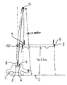
- the figure shows a schematic representation of a vehicle 1 on a Street 2, just before driving through street 2 crossing bridge 3.
- the vehicle 1 is with an on board unit 4 equipped with GPS receiver 5 and map matching system 6.
- a GPS satellite 7 transmits signals, the duration of which is a measure of the position of the Represent vehicle 1 via a GPS antenna 8 to the receiver 5th
- the bridge edge acts as a shading edge 9, so that the direct Satellite reception interrupted by the bridge 3 during the transit time becomes.
- the shading edge 9 can be determined very precisely using the last satellite signal still received to tune the determined position with that stored by the map matching system 6 to compare the absolute position of the shading edge 9. Deviations of a certain size can be used to calculate a correction value be used to correct the satellite signal.
- the invention is not limited to the above Embodiment. Rather, a number of variants are conceivable which, even with a fundamentally different type of execution, Make use of features of the invention.
Abstract
Description
Die Erfindung betrifft ein satellitengestützes map-matching-Verfahren sowie
ein On Board Unit zur Durchführung des Verfahrens gemäß den
Oberbegriffen der Patentansprüche 1 und 3.The invention relates to a satellite-based map matching method and
an on board unit to carry out the procedure according to
Preambles of
Die fahrzeugautonome Positionsbestimmung ist von herausragender Bedeutung für verschiedene Anwendungen, insbesondere für Flottenmanagement, Navigationshilfe und Straßenbenutzungsgebühren-Erfassungssysteme. Bekannt sind satellitengestützte Verfahren, die auf einer zweidimensionalen Ortung basieren. Die erreichbare Genauigkeit liegt bei ca. 50 m. Durch Einsatz eines DGPS-Verfahrens (Differential Global Positioning System) lassen sich Genauigkeiten bis ca. 5 m erzielen. Dabei werden absolute Wegpunkte, beispielsweise Funkbaken, bekannter Koordinaten zur Korrektur der satellitengestüzt, d.h. mittels GPS (Globel Positioning System), ermittelten Positionen verwendet. Bei der Funkbakenmethode ist nachteilig, daß derartige Funkbaken nur an wenigen Orten vorhanden sind und daß eine Übertragungstechnik zur Übermittlung des Signals der Funkbake an den GPS-Empfänger im Fahrzeug erforderlich ist.The autonomous position determination is outstanding Importance for various applications, especially for Fleet management, navigation aid and road toll collection systems. Satellite-based methods based on a based on two-dimensional location. The achievable accuracy is included approx. 50 m. By using a DGPS (Differential Global Positioning System), accuracies of up to approx. 5 m can be achieved. Here absolute waypoints, for example radio beacons, are becoming known Coordinates for correcting the satellite, i.e. using GPS (Globel Positioning System), determined positions used. With the radio beacon method is disadvantageous that such radio beacons only in a few places are available and that a transmission technology for transmitting the Signals the radio beacon to the GPS receiver in the vehicle is required.
Es besteht deshalb die Aufgabe, ein Verfahren der oben genannten Gattung anzugeben, das sich durch erhöhte Genauigkeit, verbesserte Verfügbarkeit und Einsparung der Übertragung der Korrekturdaten auszeichnet. There is therefore the task of a method of the above Specify genus, which improved by increased accuracy Availability and saving of the transmission of the correction data distinguished.
Erfindungsgemäß wird die Aufgabe durch die kennzeichnenden Merkmale des Anspruchs 1 gelöst. Die Erfindung basiert auf der Erkenntnis, daß sich markante Topographie-Merkmale in besonderer Weise als Referenzpunkte eignen. Die Koordinaten dieser Referenzpunkte werden einmal so genau wie möglich festgestellt und dienen dann als Datenmaterial für ein map-matching-System. Das map-matching-System vergleicht die GPS-Daten mit gespeicherten Straßenkartendaten bzw. Streckendaten, um auf diese Weise beispielsweise festzustellen, ob sich das Fahrzeug auf einer gebührenpflichtigen Straße befindet oder nicht. Die Entscheidungssicherheit wird erfindungsgemäß verbessert, indem die genau vermessenen Koordinaten, insbesondere von Brücken, mit dem GPS-Meßwert verglichen werden und aus der Abweichung ein entsprechender Korrekturwert abgeleitet wird.According to the invention, the object is characterized by the characteristic features of claim 1 solved. The invention is based on the knowledge that striking topography features in a special way as reference points own. The coordinates of these reference points become so precise determined as possible and then serve as data material for a map matching system. The map matching system compares the GPS data with stored road map data or route data in order in this way For example, determine whether the vehicle is on a chargeable basis Street or not. The decision certainty will improved according to the invention in that the precisely measured coordinates, especially of bridges, can be compared with the GPS reading and a corresponding correction value is derived from the deviation.
Gemäß Anspruch 2 findet dieser Korrekturwert zusätzlich auch Verwendung zur Eichung weiterer fahrzeugautonomer Navigationssysteme. Derart geeichte zusätzliche Navigationssysteme ermöglichen auch im Falle einer zeitweisen Abschattung, insbesondere brücken- oder tunnelbedingt, des GPS-Empfangs eine zweidimensionale Positionsermittlung in einem bestimmten Zeitinterval zu erhalten, so daß eine hundertprozentige Verfügbarkeit der Fahrzeugpositionen gegeben ist.According to claim 2, this correction value is also used for the calibration of other vehicle-autonomous navigation systems. Such calibrated additional navigation systems also allow in the case of a intermittent shading, especially due to bridges or tunnels, of GPS reception is a two-dimensional position determination in one get certain time interval, so that a hundred percent Availability of the vehicle positions is given.
Anspruch 3 kennzeichnet ein On Board Unit zur Durchführung des
Verfahrens, mit einem GPS-Empfänger und einem map-matching-System,
wobei topographische Wegpunkte mit Hilfe der in dem map-matching-System
gespeicherten Straßendaten erkannt werden und bei Erreichen eines
bestimmten Abstandes des Fahrzeuges von einem derartigen Wegpunkt die
Empfangsfeldstärke der Satellitensignale abgesenkt wird. Üblicherweise ist
der GPS-Empfänger für Signalverarbeitung im Sekundentakt eingestellt.
Diese Sekundenauflösung ist für die Feststellung von Abschattungskanten,
insbesondere bei hohen Geschwindigkeiten, nicht mehr ausreichend. Um
rechtzeitig vor dem Passieren der Abschattungskante die Empfangsfeldstärke
der Satellitensignale zu erkennen, sollte der GPS-Empfänger in
einem bestimmten Abstand vor dem zu erfassenden Wegpunkt in einen
Feldstärke-Erkennungsmode umgeschaltet werden. Dieser Abstand kann
beispielsweise auf 150m festgelegt werden. Tritt nun eine Verbindungsunterbrechung
bzw. Signal-Abschattung zwischen Satelliten und GPS-Antenne
auf, geht die Empfangsfeldstärke kurzzeitig abrupt auf einen sehr
niedrigen Wert. Dieses "Loch" in der Empfangsfeldstärke läßt sich zeitlich
exakt vermessen, so daß ein sehr genaues Kriterium zur Verfügung steht, zu
entscheiden, welcher satellitengestützte Positionsmeßwert mit der
gespeicherten absoluten Position des topographischen Wegpunktes zu
vergleichen ist. Auf diese Weise ergibt sich eine relativ einfache Möglichkeit,
einen Korrekturwert zur Korrektur des Meßfehlers des satellitengestützen
Navigationssystems zu bestimmen. Je nachdem, welcher topographischer
Wegpunkt als absoluter Wegpunkt im map-matching-System gespeichert
ist, kann dabei der Beginn oder das Ende der Empfangsunterbrechung
zugrunde gelegt werden. Denkbar ist jedoch auch eine Verknüpfung der
beiden GPS-Meßwerte, um absolute Wegpunkte zwischen den
Abschattungskanten, beispielsweise die Mitte einer Brückendurchfahrt,
berücksichtigen zu können. Wird im map-matching-Algorithmus diese
örtlich sehr genaue und eindeutige Information berücksichtigt, gestattet
diese zusätzliche Orientierung anhand topographischer Wegpunkte eine
erhebliche Verbesserung der Entscheidungssicherheit, auf welcher Straße
sich ein Fahrzeug gerade befindet. Diese Frage ist bei der Erfassung von
Straßenbenutzungsgebühren von besonderer Bedeutung. Insbesondere
Brücken- und Tunneldurchfahrten sind als topographische Wegpunkte im
allgemeinen in ausreichender Zahl und in ausreichend geringem Abstand
vorhanden.
Bevorzugt ist die rechtzeitige Erkennung einer bevorstehenden "Abschattungskante" gemäß Anspruch 4 durch einen ereignisgesteuerten Triggerausgang realisiert.The timely detection of an upcoming is preferred "Shading edge" according to claim 4 by an event-driven Trigger output realized.
Bei den üblicherweise mehrkanaligen, auf mehrere GPS-Satellitten einstellbaren GPS-Empfängern können zusätzlich gemäß Anspruch 5 Auswahlmittel zur Beschränkung der Signalauswertung auf die geeignetsten GPS-Satelliten vorgesehen sein. Bei Tunnel- und Brückendurchfahrten sind das die zenitnahen GPS-Satellitten, da die Abschattungskante bei horizontnahen Satelliten zu früh oder zu spät erfaßt wird und somit ein Meßfehler gegenüber den Absolutkoordinaten der Abschattungskante resultiert.In the case of the usually multi-channel, on several GPS satellites adjustable GPS receivers can additionally according to claim 5 Selection means to limit the signal evaluation to the most suitable GPS satellites can be provided. When passing through tunnels and bridges the GPS satellites close to the zenith, because the shading edge at horizon-near satellites is detected too early or too late and thus a Measurement error compared to the absolute coordinates of the shading edge results.
Die Erfindung wird nachfolgend anhand eines figürlich dargestellten Ausführungsbeispiels näher erläutert.The invention is illustrated below with reference to a figure Embodiment explained in more detail.
Die Figur zeigt in schematischer Darstellung ein Fahrzeug 1 auf einer
Straße 2, unmittelbar vor dem Durchfahren einer die Straße 2
überquerenden Brücke 3. Das Fahrzeug 1 ist mit einem On Board Unit 4
mit GPS-Empfänger 5 und Map-Matching-System 6 ausgestattet. Ein GPS-Satellit
7 übermittelt Signale, deren Laufzeit ein Maß für die Position des
Fahrzeuges 1 darstellen, über eine GPS-Antenne 8 an den Empfänger 5.
Der Brückenrand wirkt quasi als Abschattungskante 9, wodurch der direkte
Satellitenempfang während der Durchfahrtzeit durch die Brücke 3 unterbrochen
wird. Die Abschattungskante 9 läßt sich sehr genau feststellen,
indem das letzte noch empfangene Satellitensignal verwendet wird, um die
ermittelte Position mit der durch das map-matching-System 6 gespeicherten
absoluten Position der Abschattungskante 9 zu vergleichen. Abweichungen
in einer bestimmten Größenordnung können zur Berechnung eines Korrekturwertes
zur Korrektur des Satellitensignals verwendet werden. Größere
Abweichungen lassen darauf schließen, daß eine durch das map-matching-System
6 unter Zuhilfenahme der GPS-gestützten Positionsdaten quasi geschätzte
Zuordnung der Fahrzeugposition zu den gespeicherten Absolutkoordinaten
der Brücke 3 falsch war. Diese Zuordnung wird ca. 150 m
vor der Brücke, d. h. im Bereich der dreifachen GPS-Genauigkeit,
vorgenommen, um geeignete Satelliten 7 - im Fall der Brückendurchfahrt
zenitnahe Satelliten - auszuwählen und den Empfangs-modus des GPS-Empfängers
5 vom üblicherweise 1-Sekunden-Takt in einen erheblich
höherfrequenten Empfangsmodus umzuschalten.The figure shows a schematic representation of a vehicle 1 on a
Street 2, just before driving through street 2
Es ist ersichtlich, daß zwischen dem GPS-Satelliten 7 und der GPS-Antenne
8 eine Abschattungszone - ähnlich dem Halbschatten beim Sonnenlicht -
existiert. Diese sogenannte Fresnel-Zone 10 hat jedoch nur einen
Durchmesser von ca. ½ Wellenlänge - ca. 0,1 m - und ist demzufolge
vernachlässigbar.It can be seen that between the
Die Erfindung beschränkt sich nicht auf das vorstehend angegebene Ausführungsbeispiel. Vielmehr ist eine Anzahl von Varianten denkbar, welche auch bei grundsätzlich andersgearteter Ausführung von den Merkmalen der Erfindung Gebrauch machen.The invention is not limited to the above Embodiment. Rather, a number of variants are conceivable which, even with a fundamentally different type of execution, Make use of features of the invention.
Claims (5)
Applications Claiming Priority (2)
| Application Number | Priority Date | Filing Date | Title |
|---|---|---|---|
| DE19856187A DE19856187A1 (en) | 1998-12-05 | 1998-12-05 | Satellite-based map matching process |
| DE19856187 | 1998-12-05 |
Publications (2)
| Publication Number | Publication Date |
|---|---|
| EP1006367A2 true EP1006367A2 (en) | 2000-06-07 |
| EP1006367A3 EP1006367A3 (en) | 2001-10-17 |
Family
ID=7890108
Family Applications (1)
| Application Number | Title | Priority Date | Filing Date |
|---|---|---|---|
| EP99440336A Withdrawn EP1006367A3 (en) | 1998-12-05 | 1999-12-02 | Satellite aided map matching method |
Country Status (2)
| Country | Link |
|---|---|
| EP (1) | EP1006367A3 (en) |
| DE (1) | DE19856187A1 (en) |
Cited By (13)
| Publication number | Priority date | Publication date | Assignee | Title |
|---|---|---|---|---|
| WO2005076031A3 (en) * | 2003-10-06 | 2005-10-06 | Sirf Tech Inc | A system and method for augmenting a satellite-based navigation solution |
| WO2006086298A3 (en) * | 2005-02-07 | 2007-04-19 | Siemens Vdo Automotive Corp | Navigation system |
| US7880642B2 (en) | 2002-03-05 | 2011-02-01 | Triangle Software Llc | GPS-generated traffic information |
| CN101441262B (en) * | 2007-11-20 | 2011-11-30 | 锐迪科微电子(上海)有限公司 | Tridimensional traffic navigation method and apparatus |
| EP2550546A1 (en) * | 2010-03-25 | 2013-01-30 | Cellguide Ltd. | Gnss navigation aided by static data |
| US8619072B2 (en) | 2009-03-04 | 2013-12-31 | Triangle Software Llc | Controlling a three-dimensional virtual broadcast presentation |
| CN104504898A (en) * | 2014-12-11 | 2015-04-08 | 王东宇 | Online map matching method based on floating car data on tunnel road section |
| WO2015049044A1 (en) * | 2013-10-02 | 2015-04-09 | Audi Ag | Method for correcting position data, and motor vehicle |
| US9046924B2 (en) | 2009-03-04 | 2015-06-02 | Pelmorex Canada Inc. | Gesture based interaction with traffic data |
| US20150338524A1 (en) * | 2012-06-26 | 2015-11-26 | Ariel-University Research And Development Company Ltd. | Methods and devices for improved position determination |
| CN105551249A (en) * | 2015-12-31 | 2016-05-04 | 王东宇 | Tunnel road section online map matching method based on floating car data |
| US9644982B2 (en) | 2003-07-25 | 2017-05-09 | Pelmorex Canada Inc. | System and method for delivering departure notifications |
| US10223909B2 (en) | 2012-10-18 | 2019-03-05 | Uber Technologies, Inc. | Estimating time travel distributions on signalized arterials |
Families Citing this family (10)
| Publication number | Priority date | Publication date | Assignee | Title |
|---|---|---|---|---|
| DE10008061C2 (en) * | 2000-02-22 | 2002-02-07 | Siemens Ag | Method and device for determining position |
| DE10016178A1 (en) * | 2000-03-31 | 2001-10-11 | Bosch Gmbh Robert | Position determination method for vehicle mounted navigation system, involves correlating determined position with known area when shadowing radio signals by obstruction is detected |
| DE10044393A1 (en) * | 2000-09-08 | 2002-04-04 | Bosch Gmbh Robert | Road lane plane determination method for automobile onboard navigation system uses comparison with received satellite position signal strengths with expected signal strengths |
| DE10356496A1 (en) * | 2003-12-03 | 2005-07-07 | Siemens Ag | Position determination procedure for sub- or subscriber-station of RF communication system e.g. mobilephone, involves additional information on environment in which sub- or subscriber station is located |
| DE102005059284A1 (en) * | 2005-12-12 | 2007-06-14 | Siemens Ag | Method for determining corrected current position data, in particular for determining current vehicle positions |
| US8982116B2 (en) | 2009-03-04 | 2015-03-17 | Pelmorex Canada Inc. | Touch screen based interaction with traffic data |
| WO2012065188A2 (en) | 2010-11-14 | 2012-05-18 | Triangle Software Llc | Crowd sourced traffic reporting |
| EP2710571B1 (en) | 2011-05-18 | 2019-11-20 | Muddy River, Series 97 of Allied Security Trust 1 | System for providing traffic data and driving efficiency data |
| CA2883973C (en) | 2012-01-27 | 2021-02-23 | Edgar Rojas | Estimating time travel distributions on signalized arterials |
| DE102014215570B4 (en) * | 2014-08-06 | 2021-12-30 | Elektrobit Automotive Gmbh | Vehicle navigation system |
Citations (2)
| Publication number | Priority date | Publication date | Assignee | Title |
|---|---|---|---|---|
| US5334986A (en) * | 1992-04-09 | 1994-08-02 | U.S. Philips Corporation | Device for determining the position of a vehicle |
| US5374933A (en) * | 1993-01-05 | 1994-12-20 | Zexel Corporation | Position correction method for vehicle navigation system |
Family Cites Families (9)
| Publication number | Priority date | Publication date | Assignee | Title |
|---|---|---|---|---|
| DE3310111A1 (en) * | 1982-07-23 | 1984-09-27 | Teldix Gmbh, 6900 Heidelberg | NAVIGATION SYSTEM FOR AGRICULTURAL VEHICLES |
| DE3227547A1 (en) * | 1982-07-23 | 1984-02-02 | Teldix Gmbh, 6900 Heidelberg | Navigation system |
| JPS61137009A (en) * | 1984-12-07 | 1986-06-24 | Nissan Motor Co Ltd | Position measuring apparatus for vehicle |
| JPH02196975A (en) * | 1989-01-26 | 1990-08-03 | Nissan Motor Co Ltd | Gps navigation device for vehicle |
| KR940009235B1 (en) * | 1990-09-12 | 1994-10-01 | 미쯔비시 덴끼 가부시끼가이샤 | On-board vehicle position detector |
| JP3267310B2 (en) * | 1991-07-10 | 2002-03-18 | パイオニア株式会社 | GPS navigation device |
| US6175806B1 (en) * | 1993-07-16 | 2001-01-16 | Caterpillar Inc. | Method and apparatus for detecting cycle slips in navigation signals received at a receiver from a satellite-based navigation system |
| DE4415083A1 (en) * | 1994-04-29 | 1995-11-02 | Bosch Gmbh Robert | Procedure for the selection of signals from navigation satellites |
| KR0183299B1 (en) * | 1996-11-04 | 1999-04-15 | 삼성전자주식회사 | Navigation apparatus notifying surrounding situation of vehicle and control method thereof |
-
1998
- 1998-12-05 DE DE19856187A patent/DE19856187A1/en not_active Withdrawn
-
1999
- 1999-12-02 EP EP99440336A patent/EP1006367A3/en not_active Withdrawn
Patent Citations (2)
| Publication number | Priority date | Publication date | Assignee | Title |
|---|---|---|---|---|
| US5334986A (en) * | 1992-04-09 | 1994-08-02 | U.S. Philips Corporation | Device for determining the position of a vehicle |
| US5374933A (en) * | 1993-01-05 | 1994-12-20 | Zexel Corporation | Position correction method for vehicle navigation system |
Cited By (23)
| Publication number | Priority date | Publication date | Assignee | Title |
|---|---|---|---|---|
| US7880642B2 (en) | 2002-03-05 | 2011-02-01 | Triangle Software Llc | GPS-generated traffic information |
| US8358222B2 (en) | 2002-03-05 | 2013-01-22 | Triangle Software, Llc | GPS-generated traffic information |
| US9082303B2 (en) | 2002-03-05 | 2015-07-14 | Pelmorex Canada Inc. | Generating visual information associated with traffic |
| US9070291B2 (en) | 2002-03-05 | 2015-06-30 | Pelmorex Canada Inc. | Method for predicting a travel time for a traffic route |
| US9640073B2 (en) | 2002-03-05 | 2017-05-02 | Pelmorex Canada Inc. | Generating visual information associated with traffic |
| US9644982B2 (en) | 2003-07-25 | 2017-05-09 | Pelmorex Canada Inc. | System and method for delivering departure notifications |
| US7756639B2 (en) | 2003-10-06 | 2010-07-13 | Sirf Technology, Inc. | System and method for augmenting a satellite-based navigation solution |
| WO2005076031A3 (en) * | 2003-10-06 | 2005-10-06 | Sirf Tech Inc | A system and method for augmenting a satellite-based navigation solution |
| WO2006086298A3 (en) * | 2005-02-07 | 2007-04-19 | Siemens Vdo Automotive Corp | Navigation system |
| US7788025B2 (en) | 2005-02-07 | 2010-08-31 | Continental Automotive Systems Us, Inc. | Navigation system |
| CN101441262B (en) * | 2007-11-20 | 2011-11-30 | 锐迪科微电子(上海)有限公司 | Tridimensional traffic navigation method and apparatus |
| US9046924B2 (en) | 2009-03-04 | 2015-06-02 | Pelmorex Canada Inc. | Gesture based interaction with traffic data |
| US10289264B2 (en) | 2009-03-04 | 2019-05-14 | Uber Technologies, Inc. | Controlling a three-dimensional virtual broadcast presentation |
| US8619072B2 (en) | 2009-03-04 | 2013-12-31 | Triangle Software Llc | Controlling a three-dimensional virtual broadcast presentation |
| EP2550546A4 (en) * | 2010-03-25 | 2013-09-04 | Cellguide Ltd | Gnss navigation aided by static data |
| EP2550546A1 (en) * | 2010-03-25 | 2013-01-30 | Cellguide Ltd. | Gnss navigation aided by static data |
| US20150338524A1 (en) * | 2012-06-26 | 2015-11-26 | Ariel-University Research And Development Company Ltd. | Methods and devices for improved position determination |
| EP2864804A4 (en) * | 2012-06-26 | 2016-07-06 | Univ Ariel Res & Dev Co Ltd | Methods and devices for improved position determination |
| US10223909B2 (en) | 2012-10-18 | 2019-03-05 | Uber Technologies, Inc. | Estimating time travel distributions on signalized arterials |
| US10971000B2 (en) | 2012-10-18 | 2021-04-06 | Uber Technologies, Inc. | Estimating time travel distributions on signalized arterials |
| WO2015049044A1 (en) * | 2013-10-02 | 2015-04-09 | Audi Ag | Method for correcting position data, and motor vehicle |
| CN104504898A (en) * | 2014-12-11 | 2015-04-08 | 王东宇 | Online map matching method based on floating car data on tunnel road section |
| CN105551249A (en) * | 2015-12-31 | 2016-05-04 | 王东宇 | Tunnel road section online map matching method based on floating car data |
Also Published As
| Publication number | Publication date |
|---|---|
| EP1006367A3 (en) | 2001-10-17 |
| DE19856187A1 (en) | 2000-06-15 |
Similar Documents
| Publication | Publication Date | Title |
|---|---|---|
| EP1006367A2 (en) | Satellite aided map matching method | |
| DE102014112351B4 (en) | SENSOR-ASSISTED VEHICLE POSITIONING SYSTEM | |
| DE69433886T2 (en) | METHOD AND DEVICE FOR DETERMINING THE ABSOLUTE VEHICLE POSITION IN VEHICLE NAVIGATION SYSTEMS | |
| DE102005015387B4 (en) | Control for satellite navigation | |
| DE4327780C2 (en) | Vehicle navigation system and vehicle navigation method | |
| DE69532308T2 (en) | Detection system | |
| DE69732581T2 (en) | Navigation system using GPS data | |
| DE10050765B4 (en) | Route setting method and associated navigation device | |
| DE19505487C2 (en) | Device in a vehicle for determining the current vehicle position | |
| DE19645209B4 (en) | Locating device for a motor vehicle with a satellite receiver and locating method | |
| DE102007019309A1 (en) | Road information acquisition system, method and program | |
| DE102005004112A1 (en) | Car navigation system | |
| DE19945694A1 (en) | Vehicle current position detector in navigation apparatus, computes current position of vehicle based on dead reckoning navigation calculation result obtained by computed compensation movement distance | |
| DE102007041121A1 (en) | Sensor data processing method for driver assistance system e.g. modern motor vehicle, involves adjusting error value belonging to measured value of one sensor by another measured value of another sensor | |
| DE10021373A1 (en) | Positioning method and navigation device | |
| DE102015224694A1 (en) | Method and device for providing the vehicle navigation information in the area of a highway | |
| DE69824789T2 (en) | navigation system | |
| EP3898368B1 (en) | Method and system for determining a corrected trajectory of a vehicle | |
| DE102004016745A1 (en) | Car navigation device | |
| DE19928451A1 (en) | Location procedure with a mobile radio system | |
| DE19602053A1 (en) | Device for monitoring the distance between two objects | |
| DE10035626C2 (en) | Navigation device and method for position correction | |
| DE102014006444A1 (en) | Method for determining a position of a motor vehicle | |
| DE4217555A1 (en) | Map-based location and navigation system for motor vehicle - corrects distance covered for tyre wear and pressure errors using known positions of detected bridges and tunnels | |
| EP0840137B1 (en) | Method of satellite navigation |
Legal Events
| Date | Code | Title | Description |
|---|---|---|---|
| PUAI | Public reference made under article 153(3) epc to a published international application that has entered the european phase |
Free format text: ORIGINAL CODE: 0009012 |
|
| AK | Designated contracting states |
Kind code of ref document: A2 Designated state(s): AT BE CH CY DE DK ES FI FR GB GR IE IT LI LU MC NL PT SE |
|
| AX | Request for extension of the european patent |
Free format text: AL;LT;LV;MK;RO;SI |
|
| PUAL | Search report despatched |
Free format text: ORIGINAL CODE: 0009013 |
|
| AK | Designated contracting states |
Kind code of ref document: A3 Designated state(s): AT BE CH CY DE DK ES FI FR GB GR IE IT LI LU MC NL PT SE |
|
| AX | Request for extension of the european patent |
Free format text: AL;LT;LV;MK;RO;SI |
|
| AKX | Designation fees paid |
Free format text: AT BE CH CY DE DK ES FI FR GB GR IE IT LI LU MC NL PT SE |
|
| STAA | Information on the status of an ep patent application or granted ep patent |
Free format text: STATUS: THE APPLICATION IS DEEMED TO BE WITHDRAWN |
|
| 18D | Application deemed to be withdrawn |
Effective date: 20020418 |