EP0967708A2 - Electrical motor - Google Patents
Electrical motor Download PDFInfo
- Publication number
- EP0967708A2 EP0967708A2 EP99111512A EP99111512A EP0967708A2 EP 0967708 A2 EP0967708 A2 EP 0967708A2 EP 99111512 A EP99111512 A EP 99111512A EP 99111512 A EP99111512 A EP 99111512A EP 0967708 A2 EP0967708 A2 EP 0967708A2
- Authority
- EP
- European Patent Office
- Prior art keywords
- stator
- cooling
- cooling jacket
- electric motor
- headstock
- Prior art date
- Legal status (The legal status is an assumption and is not a legal conclusion. Google has not performed a legal analysis and makes no representation as to the accuracy of the status listed.)
- Withdrawn
Links
Images

Classifications
-
- H—ELECTRICITY
- H02—GENERATION; CONVERSION OR DISTRIBUTION OF ELECTRIC POWER
- H02K—DYNAMO-ELECTRIC MACHINES
- H02K1/00—Details of the magnetic circuit
- H02K1/06—Details of the magnetic circuit characterised by the shape, form or construction
- H02K1/12—Stationary parts of the magnetic circuit
- H02K1/18—Means for mounting or fastening magnetic stationary parts on to, or to, the stator structures
- H02K1/185—Means for mounting or fastening magnetic stationary parts on to, or to, the stator structures to outer stators
-
- H—ELECTRICITY
- H02—GENERATION; CONVERSION OR DISTRIBUTION OF ELECTRIC POWER
- H02K—DYNAMO-ELECTRIC MACHINES
- H02K5/00—Casings; Enclosures; Supports
- H02K5/04—Casings or enclosures characterised by the shape, form or construction thereof
- H02K5/20—Casings or enclosures characterised by the shape, form or construction thereof with channels or ducts for flow of cooling medium
- H02K5/207—Casings or enclosures characterised by the shape, form or construction thereof with channels or ducts for flow of cooling medium with openings in the casing specially adapted for ambient air
-
- H—ELECTRICITY
- H02—GENERATION; CONVERSION OR DISTRIBUTION OF ELECTRIC POWER
- H02K—DYNAMO-ELECTRIC MACHINES
- H02K1/00—Details of the magnetic circuit
- H02K1/06—Details of the magnetic circuit characterised by the shape, form or construction
- H02K1/12—Stationary parts of the magnetic circuit
- H02K1/20—Stationary parts of the magnetic circuit with channels or ducts for flow of cooling medium
-
- H—ELECTRICITY
- H02—GENERATION; CONVERSION OR DISTRIBUTION OF ELECTRIC POWER
- H02K—DYNAMO-ELECTRIC MACHINES
- H02K9/00—Arrangements for cooling or ventilating
- H02K9/14—Arrangements for cooling or ventilating wherein gaseous cooling medium circulates between the machine casing and a surrounding mantle
Definitions
- the invention relates to an electric motor with air cooling.
- DE 22 33 860 describes an electric motor, the stator is encased in the circumferential direction with a corrugated sheet.
- the corrugated sheet is determined by a welded joint Sheet metal parts fixed to the stator.
- the disadvantage here is the different heat transfer stator to sheet metal casing, uneven thermal expansion of the sheet metal casing due to the punctual welding processes and lack Absorption and transmission of radial and axial forces Sheet metal cover.
- the invention is therefore based on the object of an electric motor to create whose active parts are sufficiently cooled become.
- Another object of the invention is for one Electric motor within a given housing a comparative to create efficient cooling that in addition to above average Heat transfer numbers sufficient stability with regard to the absorption of the radial and axial forces and of the torque.
- the self-supporting cooling jacket avoids that occurring during assembly, particularly in the case of corrugated sheets Accordion effect ".
- the cooling jacket having a meandering arrangement of axial cooling channels requires a small amount of space with comparatively high cooling efficiency.
- a special design of the cooling jacket enables, in addition to the direct or countercurrent principle, targeted guidance of the cooling medium, preferably gaseous cooling media, such as air in thermal problem areas.
- An efficient heat transfer between the headstock and the cooling jacket on the one hand, and between the stator and the cooling jacket on the other hand is preferably produced by means of a thermal paste in connection with a shrinking process.
- the cooling jacket consists of part of an extruded profile, preferably an aluminum extruded profile. This can due to the good thermal conductivity of aluminum the heat loss quickly from the Headstock and the stator are removed. The radius of curvature of the stator and the headstock Cooling jacket sections contribute to a further improvement the heat transfer and thus the cooling. For extruded profiles the desired cooling jacket length can be cut off adapt to the respective engine. Thus, the cooling jacket be produced economically.
- Deflection devices and fasteners e.g. axial Threaded bolts
- fasteners e.g. axial Threaded bolts
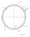
- the 1 shows a cooling jacket 1 which has axial cooling channels 2.
- the axial cooling channels 2 are formed by a meandering extruded aluminum profile 4 running in the circumferential direction of a stator 3.
- the wall thickness of the extruded aluminum profile 4 is designed such that when the cooling jacket 1 is installed over the stator 3 and into a headstock 5, none Accordion effect "can occur.
- the cooling jacket 1 can be shrunk on or pressed on, and thus can absorb the torque of the motor. During the shrinking process, the cooling jacket 1 is heated inductively or in an oven.
- Four meanders 6 of the aluminum extruded profile 4 are made of solid material in order to attach any functional parts of the electric motor there, such as threaded sleeves 7 for attaching flanges 8 or deflection devices 9 of an air stream, the sum of the cooling jacket surface lying directly on the stator 3 or on the inside of a housing designed as a headstock 5 is approximately the same;
- the contact surfaces 10 of the cooling jacket 1 are adapted to the respective radii of curvature of the stator 3 and headstock 5 in order to further increase the cooling efficiency.
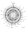
- FIG. 2 shows the installation of such a cooling jacket 1 in a Electric motor which is surrounded by the headstock 5.
- a rotor 11 is arranged with essentially hexagonal Permanent magnets 12 shown in a laminated core 13.
- the rotor 11 is arranged on a sleeve 24.
- the Laminated core of stator 3 shows poles 14 formed Stator 3 extends in the circumferential direction of cooling jacket 1 with its cooling channels 2 formed by meanders, which extend substantially axially.
- the full material Meanders 6 are equipped with threaded sleeves 7. In radial Direction further out closes after the Cooling jacket 1 of the headstock 5, which comprises devices 15, to the inlet or outlet of a cooling medium (cooling air flow) are provided. Both the cooling air supply as well as the removal in the radial or axial direction.
- FIG. 3 shows a basic illustration of an electric motor in a headstock 5 in longitudinal section. It is on the an end face 16 of the stator lamination stack a cooling flow inlet 17 provided in the headstock, which is also aif of the opposite Side of the stator 3 or in the middle of the stator 3 can be arranged. Likewise, the exit of the Cooling air flow 18 optionally selected axially and / or radially become.
- Through deflection devices 19 and / or through openings 20 on the end faces of the stator 3 can cool in the countercurrent or cocurrent principle.
- the one in the Headstock 5 entering cooling air stream cools through the deflection devices 19 both the winding heads 21 and the Bearing 22 of the shaft 23 of the rotor 11.
Abstract
Description
Die Erfindung betrifft einen Elektromotor mit Luftkühlung.The invention relates to an electric motor with air cooling.
Die DE 22 33 860 beschreibt einen Elektromotor, dessen Stator in Umfangsrichtung mit einem gewellten Blech umhüllt ist. Das gewellte Blech ist durch eine Schweißverbindung bestimmter Blechpartien am Stator fixiert.DE 22 33 860 describes an electric motor, the stator is encased in the circumferential direction with a corrugated sheet. The corrugated sheet is determined by a welded joint Sheet metal parts fixed to the stator.
Nachteilig dabei ist der unterschiedliche Wärmeübergang Stator zu Blechhülle, ungleichmäßige Wärmeausdehnung der Blechhülle aufgrund der punktuellen Schweißvorgänge und mangelnde Aufnahme und Übertragung von radialen und axialen Kräften der Blechhülle.The disadvantage here is the different heat transfer stator to sheet metal casing, uneven thermal expansion of the sheet metal casing due to the punctual welding processes and lack Absorption and transmission of radial and axial forces Sheet metal cover.
Demnach liegt der Erfindung die Aufgabe zugrunde, einen Elektromotor zu schaffen, dessen Aktivteile ausreichend gekühlt werden.The invention is therefore based on the object of an electric motor to create whose active parts are sufficiently cooled become.
Außerdem ist eine weitere Aufgabe der Erfindung, für einen Elektromotor innerhalb eines vorgegebenen Gehäuses eine vergleichsweise effiziente Kühlung zu schaffen, die neben überdurchschnittlichen Wärmeübergangszahlen ausreichende Stabilität bzgl. der Aufnahme der radialen und axialen Kräfte und des Drehmoments aufweist.Another object of the invention is for one Electric motor within a given housing a comparative to create efficient cooling that in addition to above average Heat transfer numbers sufficient stability with regard to the absorption of the radial and axial forces and of the torque.
Die Aufgaben werden durch einen Elektromotor gelöst, der folgende Merkmale aufweist:
- ein Gehäuse, vorzugsweise ein Spindelkasten,
- einen Rotor und einen Stator,
- einen in Umfangsrichtung des Stators mäanderförmigen und dadurch im wesentlichen axiale Kühlkanäle bildenden selbsttragenden Kühlmantel,
- eine wärmeleitende Befestigung des Kühlmantels mit dem Stator und/oder dem Spindelkasten durch stoff-, form-, oder reibschlüssige wärmeleitende Verbindungen,
- Umlenkvorrichtungen an den Stirnseiten des Statorblechpakets zur Führung des Kühlmediums in Gegen- oder Gleichstromprinzip,
- Ein- und Auslaßöffnungen zur Führung des Kühlmediums zum und vom Kühlmantel im Bereich der Stirnseiten des Blechpakets des Stators und/oder zwischen den Stirnseiten des Blechpakets des Stators.
- a housing, preferably a headstock,
- a rotor and a stator,
- a self-supporting cooling jacket which is meandering in the circumferential direction of the stator and thereby essentially forms axial cooling channels,
- a heat-conducting fastening of the cooling jacket to the stator and / or the headstock by means of material, form, or frictional heat-conducting connections,
- Deflection devices on the end faces of the stator laminated core for guiding the cooling medium in the countercurrent or cocurrent principle,
- Inlet and outlet openings for guiding the cooling medium to and from the cooling jacket in the region of the end faces of the laminated core of the stator and / or between the end faces of the laminated core of the stator.
Der selbsttragende Kühlmantel vermeidet während der Montage
einen vor allem bei gewellten Blechen auftretenden ![]()
![]()
In einer weiteren Ausführungsform besteht der Kühlmantel aus einem Teil eines Strangpreßprofil, vorzugsweise einem Aluminiumstrangpressprofil. Dadurch kann aufgrund der guten Wärmeleitfähigkeit von Aluminium die Verlustwärme schnell aus dem Spindelkasten und dem Stator abgeführt werden. Die dem Krümmungsradius des Stators und des Spindelkastens angepassten Kühlmantelabschnitte tragen zu einer weiteren Verbesserung des Wärmeübergangs und damit der Kühlung bei. Bei Strangpreßprofilen läßt sich durch Abschneiden die gewünschte Kühlmantellänge dem jeweiligen Motor anpassen. Somit kann der Kühlmantel wirtschaftlich hergestellt werden. In a further embodiment, the cooling jacket consists of part of an extruded profile, preferably an aluminum extruded profile. This can due to the good thermal conductivity of aluminum the heat loss quickly from the Headstock and the stator are removed. The radius of curvature of the stator and the headstock Cooling jacket sections contribute to a further improvement the heat transfer and thus the cooling. For extruded profiles the desired cooling jacket length can be cut off adapt to the respective engine. Thus, the cooling jacket be produced economically.
In einer weiteren Ausführungsform können bereits für den Betrieb des Elektromotors notwendigen Funktionsteile, wie z.B. Umlenkvorrichtungen und Befestigungsmittel, wie z.B. axiale Gewindebolzen, im Strangpreßprofil enthalten sein, um so die weitere Montage zu vereinfachen und den gesamten Aufbau kompakter zu gestalten.In a further embodiment, they can already be used for operation necessary functional parts of the electric motor, e.g. Deflection devices and fasteners, e.g. axial Threaded bolts, be included in the extruded profile, so the simplify further assembly and make the entire structure more compact to design.
Die Erfindung sowie weitere vorteilhafte Ausgestaltungen der Erfindung gemäß den Merkmalen der Unteransprüche werden im folgenden anhand eines schematisch dargestellten Ausführungsbeispiels in der Zeichnung näher erläutert; darin zeigen:
- FIG 1
- einen Querschnitt eines Kühlmantels,
- FIG 2
- einen Querschnitt eines Elektromotors mit einem derartigen Kühlmantel,
- FIG 3
- einen Längsschnitt eines Elektromotors mit einem derartigen Kühlmantel.
- FIG. 1
- a cross section of a cooling jacket,
- FIG 2
- 3 shows a cross section of an electric motor with such a cooling jacket,
- FIG 3
- a longitudinal section of an electric motor with such a cooling jacket.
FIG 1 zeigt einen Kühlmantel 1, der axiale Kühlkanäle 2 aufweist.
Die axialen Kühlkanäle 2 werden durch ein in Umfangsrichtung
eines Stators 3 verlaufendes mäanderförmigen Aluminiumstrangpreßprofil
4 gebildet. Dabei ist die Wanddicke des
Aluminiumstrangpreßprofils 4 derart ausgebildet, daß bei Montage
des Kühlmantels 1 über den Stator 3 und in einen Spindelkasten
5 kein
FIG 2 zeigt den Einbau eines derartigen Kühlmantels 1 in einen
Elektromotor, der von dem Spindelkasten 5 umgeben ist.
Dabei ist ein Rotor 11 mit im wesentlichen, sechseckig angeordneten
Permanentmagneten 12 in einem Blechpaket 13 dargestellt.
Der Rotor 11 ist auf einer Hülse 24 angeordnet. Das
Blechpaket des Stators 3 zeigt ausgebildete Pole 14. Um den
Stator 3 erstreckt sich in Umfangsrichtung der Kühlmantel 1
mit seinen durch Mäander gebildeten Kühlkanälen 2, die sich
im wesentlichen axial erstrecken. Die mit Vollmaterial versehenen
Mäander 6 sind mit Gewindehülsen 7 ausgestattet. In radialer
Richtung weiter nach außen schließt sich nach dem
Kühlmantel 1 der Spindelkasten 5 an, der Vorrichtungen 15 umfaßt,
die zum Ein- bzw. Auslaß eines Kühlmediums (Kühlluftstrom)
vorgesehen sind. Dabei kann sowohl die Kühlluftzufuhr
als auch die -abfuhr in radialer oder axialer Richtung erfolgen.2 shows the installation of such a
FIG 3 zeigt eine prinzipielle Darstellung eines Elektromotors
in einem Spindelkasten 5 im Längsschnitt. Dabei ist an der
einen Stirnseite 16 des Statorblechpakets ein Kühlstromeintritt
17 im Spindelkasten vorgesehen, der auch aif der gegenüberliegenden
Seite des Stators 3 oder in der Mitte des Stators
3 angeordnet sein kann. Ebenso kann der Austritt des
Kühlluftstroms 18 wahlweise axial und/oder radial gewählt
werden. Durch Umlenkvorrichtungen 19 und/oder Durchtrittsöffnungen
20 an den Stirnseiten des Stators 3 kann die Kühlung
im Gegenstrom- oder Gleichstromprinzip erfolgen. Der in den
Spindelkasten 5 eintretende Kühlluftstrom kühlt durch die Umlenkvorrichtungen
19 sowohl die Wickelköpfe 21 als auch die
Lager 22 der Welle 23 des Rotors 11. Der aus dem Spindelkasten
5 austretende Kühlluftstrom kühlte auf der dem Einlaß
gegenüberliegenden Seite ebenso die Wickelköpfe 21 und die
Lager 22 der Welle 23.3 shows a basic illustration of an electric motor
in a
Claims (4)
Applications Claiming Priority (2)
| Application Number | Priority Date | Filing Date | Title |
|---|---|---|---|
| DE19828406 | 1998-06-25 | ||
| DE19828406A DE19828406A1 (en) | 1998-06-25 | 1998-06-25 | Electric motor |
Publications (2)
| Publication Number | Publication Date |
|---|---|
| EP0967708A2 true EP0967708A2 (en) | 1999-12-29 |
| EP0967708A3 EP0967708A3 (en) | 2001-01-24 |
Family
ID=7872042
Family Applications (1)
| Application Number | Title | Priority Date | Filing Date |
|---|---|---|---|
| EP99111512A Withdrawn EP0967708A3 (en) | 1998-06-25 | 1999-06-14 | Electrical motor |
Country Status (2)
| Country | Link |
|---|---|
| EP (1) | EP0967708A3 (en) |
| DE (1) | DE19828406A1 (en) |
Cited By (10)
| Publication number | Priority date | Publication date | Assignee | Title |
|---|---|---|---|---|
| EP1174988A1 (en) * | 2000-07-17 | 2002-01-23 | Conception et Développement Michelin S.A. | Stator of rotating electrical machine |
| EP1179882A2 (en) * | 2000-08-10 | 2002-02-13 | Kienle & Spiess Stanz- und Druckgiesswerk GmbH | Part of a stator and/or rotor for electric actuators or generators, especially for the food industry |
| WO2002060036A2 (en) * | 2001-01-25 | 2002-08-01 | Baumüller Nürnberg GmbH | Cooling of stator by corrugated hose in an electric machine |
| EP1257037A1 (en) * | 2001-05-10 | 2002-11-13 | Va Tech Elin EBG Motoren GmbH | Permanently magnetized electric machine |
| DE102008017376A1 (en) | 2008-04-05 | 2009-10-15 | Aerodyn Engineering Gmbh | Generator housing for a wind turbine |
| WO2010029334A1 (en) | 2008-09-12 | 2010-03-18 | Controlled Power Technologies Ltd | Apparatus and manufacturing process for an electrical machine |
| EP1175300B2 (en) † | 2000-02-18 | 2010-03-31 | Uteco Holding S.P.A. | Multiple-color flexographic rotary printing machine |
| EP2975729A1 (en) * | 2014-07-17 | 2016-01-20 | Siemens Aktiengesellschaft | Generator of a wind power plant |
| DE102016225521A1 (en) | 2016-12-20 | 2018-06-21 | Bayerische Motoren Werke Aktiengesellschaft | Cooling jacket housing, in particular for an electrical machine |
| DE102020207236A1 (en) | 2020-06-10 | 2021-12-16 | Zf Friedrichshafen Ag | Stator arrangement of an electrical machine and electrical machine for driving a motor vehicle |
Families Citing this family (1)
| Publication number | Priority date | Publication date | Assignee | Title |
|---|---|---|---|---|
| DE102012219943B4 (en) | 2012-10-31 | 2019-12-05 | Schaeffler Technologies AG & Co. KG | Cooling device for an electric motor |
Citations (10)
| Publication number | Priority date | Publication date | Assignee | Title |
|---|---|---|---|---|
| DE645329C (en) * | 1932-12-29 | 1937-05-26 | Siemens Schuckertwerke Akt Ges | Arrangement to improve the cooling of closed electrical machines |
| US2413525A (en) * | 1944-02-10 | 1946-12-31 | Allis Louis Co | Totally enclosed dynamoelectric machine |
| US2422824A (en) * | 1943-04-08 | 1947-06-24 | Electric Machinery Mfg Co | Dynamoelectric machine |
| FR1046005A (en) * | 1951-11-29 | 1953-12-02 | Ragonot Ets | DC amplifying dynamo |
| FR64521E (en) * | 1953-07-22 | 1955-11-14 | Ragonot Ets | DC amplifying dynamo |
| CH356193A (en) * | 1957-03-23 | 1961-08-15 | Bbc Brown Boveri & Cie | Device for cooling closed electrical machines |
| DE1488561A1 (en) * | 1965-04-23 | 1969-08-07 | Loher & Soehne Gmbh | Internal ventilation of larger, surface-cooled electric motors |
| JPS5529263A (en) * | 1978-08-21 | 1980-03-01 | Mitsubishi Electric Corp | Device for cooling rotary electric machine |
| JPS55150755A (en) * | 1979-05-15 | 1980-11-22 | Toshiba Corp | Totally-enclosed rotating electric machine |
| DE3707422A1 (en) * | 1987-03-07 | 1988-09-15 | Bosch Gmbh Robert | METHOD FOR ATTACHING THE STAND PACKAGE TO AN ELECTRIC GENERATOR AND ELECTRIC GENERATOR |
Family Cites Families (7)
| Publication number | Priority date | Publication date | Assignee | Title |
|---|---|---|---|---|
| DE126779C (en) * | ||||
| DE388676C (en) * | 1919-08-15 | 1924-01-17 | John Bulkley Wiard | Device for holding the stand of dynamo-electric machines |
| FR1016478A (en) * | 1950-04-19 | 1952-11-13 | Moteurs Leroy | New casing for electric motor and manufacturing process |
| DE926676C (en) * | 1950-06-15 | 1955-04-21 | Alwin Karl Dipl-Ing Borchers | Electric machine |
| SE369358B (en) * | 1971-07-14 | 1974-08-19 | Asea Ab | |
| DE3134080A1 (en) * | 1981-08-28 | 1983-04-14 | Robert Bosch Gmbh, 7000 Stuttgart | ELECTRIC MACHINE, ESPECIALLY THREE-PHASE GENERATOR, WITH INTERNAL COOLING CHANNELS |
| DE4107399A1 (en) * | 1991-03-08 | 1992-09-10 | Hermann R Oehme | Electromagnetic energy converter with stator made of dynamo plate - has rotor located in stator area, stator being formed as supporting part with recesses for guiding coolant |
-
1998
- 1998-06-25 DE DE19828406A patent/DE19828406A1/en not_active Ceased
-
1999
- 1999-06-14 EP EP99111512A patent/EP0967708A3/en not_active Withdrawn
Patent Citations (10)
| Publication number | Priority date | Publication date | Assignee | Title |
|---|---|---|---|---|
| DE645329C (en) * | 1932-12-29 | 1937-05-26 | Siemens Schuckertwerke Akt Ges | Arrangement to improve the cooling of closed electrical machines |
| US2422824A (en) * | 1943-04-08 | 1947-06-24 | Electric Machinery Mfg Co | Dynamoelectric machine |
| US2413525A (en) * | 1944-02-10 | 1946-12-31 | Allis Louis Co | Totally enclosed dynamoelectric machine |
| FR1046005A (en) * | 1951-11-29 | 1953-12-02 | Ragonot Ets | DC amplifying dynamo |
| FR64521E (en) * | 1953-07-22 | 1955-11-14 | Ragonot Ets | DC amplifying dynamo |
| CH356193A (en) * | 1957-03-23 | 1961-08-15 | Bbc Brown Boveri & Cie | Device for cooling closed electrical machines |
| DE1488561A1 (en) * | 1965-04-23 | 1969-08-07 | Loher & Soehne Gmbh | Internal ventilation of larger, surface-cooled electric motors |
| JPS5529263A (en) * | 1978-08-21 | 1980-03-01 | Mitsubishi Electric Corp | Device for cooling rotary electric machine |
| JPS55150755A (en) * | 1979-05-15 | 1980-11-22 | Toshiba Corp | Totally-enclosed rotating electric machine |
| DE3707422A1 (en) * | 1987-03-07 | 1988-09-15 | Bosch Gmbh Robert | METHOD FOR ATTACHING THE STAND PACKAGE TO AN ELECTRIC GENERATOR AND ELECTRIC GENERATOR |
Non-Patent Citations (2)
| Title |
|---|
| PATENT ABSTRACTS OF JAPAN vol. 004, no. 059 (E-009), 2. Mai 1980 (1980-05-02) & JP 55 029263 A (MITSUBISHI ELECTRIC CORP), 1. März 1980 (1980-03-01) * |
| PATENT ABSTRACTS OF JAPAN vol. 005, no. 023 (E-045), 12. Februar 1981 (1981-02-12) & JP 55 150755 A (TOSHIBA CORP), 22. November 1980 (1980-11-22) * |
Cited By (17)
| Publication number | Priority date | Publication date | Assignee | Title |
|---|---|---|---|---|
| EP1175300B2 (en) † | 2000-02-18 | 2010-03-31 | Uteco Holding S.P.A. | Multiple-color flexographic rotary printing machine |
| EP1901416A2 (en) * | 2000-07-17 | 2008-03-19 | Michelin Recherche et Technique S.A. | Stator of rotating electrical machine |
| EP1174988A1 (en) * | 2000-07-17 | 2002-01-23 | Conception et Développement Michelin S.A. | Stator of rotating electrical machine |
| US6943479B2 (en) | 2000-07-17 | 2005-09-13 | Conception Et Developpement Michelin S.A. | Stator for an electrical rotating machine |
| EP1901416A3 (en) * | 2000-07-17 | 2009-10-21 | Michelin Recherche et Technique S.A. | Stator of rotating electrical machine |
| EP1179882A2 (en) * | 2000-08-10 | 2002-02-13 | Kienle & Spiess Stanz- und Druckgiesswerk GmbH | Part of a stator and/or rotor for electric actuators or generators, especially for the food industry |
| EP1179882A3 (en) * | 2000-08-10 | 2004-01-02 | Kienle & Spiess Stanz- und Druckgiesswerk GmbH | Part of a stator and/or rotor for electric actuators or generators, especially for the food industry |
| WO2002060036A3 (en) * | 2001-01-25 | 2002-09-26 | Baumueller Nuernberg Gmbh | Cooling of stator by corrugated hose in an electric machine |
| US6822352B2 (en) * | 2001-01-25 | 2004-11-23 | Baumüller Nürnberg GmbH | Cooling of stator by corrugated hose in an electric machine |
| WO2002060036A2 (en) * | 2001-01-25 | 2002-08-01 | Baumüller Nürnberg GmbH | Cooling of stator by corrugated hose in an electric machine |
| EP1257037A1 (en) * | 2001-05-10 | 2002-11-13 | Va Tech Elin EBG Motoren GmbH | Permanently magnetized electric machine |
| DE102008017376A1 (en) | 2008-04-05 | 2009-10-15 | Aerodyn Engineering Gmbh | Generator housing for a wind turbine |
| WO2010029334A1 (en) | 2008-09-12 | 2010-03-18 | Controlled Power Technologies Ltd | Apparatus and manufacturing process for an electrical machine |
| EP2975729A1 (en) * | 2014-07-17 | 2016-01-20 | Siemens Aktiengesellschaft | Generator of a wind power plant |
| DE102016225521A1 (en) | 2016-12-20 | 2018-06-21 | Bayerische Motoren Werke Aktiengesellschaft | Cooling jacket housing, in particular for an electrical machine |
| WO2018114099A1 (en) | 2016-12-20 | 2018-06-28 | Bayerische Motoren Werke Aktiengesellschaft | Cooling jacket housing, in particular for an electric machine |
| DE102020207236A1 (en) | 2020-06-10 | 2021-12-16 | Zf Friedrichshafen Ag | Stator arrangement of an electrical machine and electrical machine for driving a motor vehicle |
Also Published As
| Publication number | Publication date |
|---|---|
| DE19828406A1 (en) | 1999-12-30 |
| EP0967708A3 (en) | 2001-01-24 |
Similar Documents
| Publication | Publication Date | Title |
|---|---|---|
| DE60110009T2 (en) | Alternator for vehicles | |
| DE102008022105B4 (en) | Liquid-cooled electrical machine and method for cooling such an electrical machine | |
| DE4038663C2 (en) | AC alternator for vehicles | |
| DE2704189C2 (en) | Backflow-cooled dynamo-electric machine | |
| WO2006106086A1 (en) | Electric machine comrpising a housing for liquid cooling | |
| EP1614205A2 (en) | Electric machine provided with cooled metal stacks and windings of the stator rotor thereof | |
| DE10258778A1 (en) | Electrical machine with heat pipes | |
| EP2399334B1 (en) | Traction motor with a housing | |
| DE102018117463A1 (en) | Stator for an electric motor, electric motor with the stator and electric drive with the electric motor | |
| EP0967708A2 (en) | Electrical motor | |
| EP0660492B1 (en) | Cooling system for a motor | |
| DE19921320C2 (en) | magnet type heater | |
| DE4229395C2 (en) | Surface-cooled, closed electrical machine | |
| WO1994023485A1 (en) | Motor spindle for a machine tool | |
| DE102011056007A1 (en) | Cooling system for a rotating electrical machine of highest power density | |
| WO2002023699A2 (en) | Liquid-cooled electromotor | |
| DE1604274B2 (en) | DEVICE FOR HEATING OR COOLING AIR BY MEANS OF A CIRCULATING IMPELLER WITH THERMOELECTRIC ELEMENTS THAT WORK ON THE PELTIER EFFECT | |
| DE102018101640A1 (en) | Electric drive device | |
| DE10307813A1 (en) | Electric machine for wind power generator or pod drive in ship, has axial cooling channels arranged in rotor, forming closed cooling circuit | |
| EP1145409B1 (en) | Electric machine with cooled rotor | |
| WO2000048290A1 (en) | Electric machine | |
| AT403864B (en) | COOLING SYSTEM FOR AN ELECTRICAL MACHINE | |
| DE102019205762A1 (en) | Electric machine with torque support in the housing | |
| EP3070815A1 (en) | Stator with thermal connection of vent tubes | |
| EP0071046A1 (en) | Heating generator with liquid cooling system |
Legal Events
| Date | Code | Title | Description |
|---|---|---|---|
| PUAI | Public reference made under article 153(3) epc to a published international application that has entered the european phase |
Free format text: ORIGINAL CODE: 0009012 |
|
| AK | Designated contracting states |
Kind code of ref document: A2 Designated state(s): AT BE CH CY DE DK ES FI FR GB GR IE IT LI LU MC NL PT SE |
|
| AX | Request for extension of the european patent |
Free format text: AL;LT;LV;MK;RO;SI |
|
| PUAL | Search report despatched |
Free format text: ORIGINAL CODE: 0009013 |
|
| AK | Designated contracting states |
Kind code of ref document: A3 Designated state(s): AT BE CH CY DE DK ES FI FR GB GR IE IT LI LU MC NL PT SE |
|
| AX | Request for extension of the european patent |
Free format text: AL;LT;LV;MK;RO;SI |
|
| AKX | Designation fees paid | ||
| REG | Reference to a national code |
Ref country code: DE Ref legal event code: 8566 |
|
| STAA | Information on the status of an ep patent application or granted ep patent |
Free format text: STATUS: THE APPLICATION IS DEEMED TO BE WITHDRAWN |
|
| 18D | Application deemed to be withdrawn |
Effective date: 20010725 |