EP0930514A2 - System and method for identifying position of mobile terminal - Google Patents
System and method for identifying position of mobile terminal Download PDFInfo
- Publication number
- EP0930514A2 EP0930514A2 EP98124879A EP98124879A EP0930514A2 EP 0930514 A2 EP0930514 A2 EP 0930514A2 EP 98124879 A EP98124879 A EP 98124879A EP 98124879 A EP98124879 A EP 98124879A EP 0930514 A2 EP0930514 A2 EP 0930514A2
- Authority
- EP
- European Patent Office
- Prior art keywords
- mobile terminal
- field intensity
- received field
- repeater
- transmitter
- Prior art date
- Legal status (The legal status is an assumption and is not a legal conclusion. Google has not performed a legal analysis and makes no representation as to the accuracy of the status listed.)
- Ceased
Links
- 238000000034 method Methods 0.000 title claims description 27
- 238000005259 measurement Methods 0.000 claims description 20
- 230000005540 biological transmission Effects 0.000 claims description 19
- 230000008569 process Effects 0.000 description 19
- 238000004891 communication Methods 0.000 description 17
- 230000008901 benefit Effects 0.000 description 5
- 238000010586 diagram Methods 0.000 description 5
- 230000005684 electric field Effects 0.000 description 3
- 230000006870 function Effects 0.000 description 3
- 230000007274 generation of a signal involved in cell-cell signaling Effects 0.000 description 3
- 238000010276 construction Methods 0.000 description 2
- 238000009434 installation Methods 0.000 description 2
- 230000004044 response Effects 0.000 description 2
- 230000001413 cellular effect Effects 0.000 description 1
- 238000012986 modification Methods 0.000 description 1
- 230000004048 modification Effects 0.000 description 1
Images

Classifications
-
- H—ELECTRICITY
- H04—ELECTRIC COMMUNICATION TECHNIQUE
- H04W—WIRELESS COMMUNICATION NETWORKS
- H04W64/00—Locating users or terminals or network equipment for network management purposes, e.g. mobility management
-
- G—PHYSICS
- G01—MEASURING; TESTING
- G01S—RADIO DIRECTION-FINDING; RADIO NAVIGATION; DETERMINING DISTANCE OR VELOCITY BY USE OF RADIO WAVES; LOCATING OR PRESENCE-DETECTING BY USE OF THE REFLECTION OR RERADIATION OF RADIO WAVES; ANALOGOUS ARRANGEMENTS USING OTHER WAVES
- G01S5/00—Position-fixing by co-ordinating two or more direction or position line determinations; Position-fixing by co-ordinating two or more distance determinations
- G01S5/02—Position-fixing by co-ordinating two or more direction or position line determinations; Position-fixing by co-ordinating two or more distance determinations using radio waves
- G01S5/14—Determining absolute distances from a plurality of spaced points of known location
Definitions
- the present invention relates to a location system, a location method, and a mobile terminal. More particularly, the present invention relates to a location system and a location method to identify the position of a mobile terminal that can communicate based on a repeater installed in a radio zone, and such a mobile terminal.
- a small zone radio communication system such as a PHS (Personal Handyphone System) is known.
- the PHS portable terminal representative of a mobile terminal in a small zone radio communication system is used as a cordless telephone at home. It can also be carried outside to be connected to public and digital networks via indoor or outdoor public repeaters and the like. It can be used literally as a handy portable telephone.
- the PHS greatly differs from the existing cellular type system in that the PHS employs the small zone system.
- a system of identifying the position of a mobile terminal is proposed according to the received electric field intensity of the radio wave of the repeater in the neighborhood of the mobile terminal that is transmitted therefrom and the identification code of the repeater, taking advantage of the feature that the radio zone of the PHS is of a small area.
- an object of the present invention is to improve the accuracy of identifying the position of a mobile terminal with the minimum cost.
- a location system for identifying the position of a mobile terminal that can communicate based on a repeater installed in a radio zone, includes: a plurality of transmitter units installed around the mobile terminal apart from the repeater to send transmitter unit identification information that allows identification of each transmitter unit to the mobile terminal by a wave of a predetermined transmission output; a received field intensity measurement unit that can measure the received field intensity at the mobile terminal from the plurality of transmitter units for every different transmitter unit; and a position identify unit identifying the position of the mobile terminal according to the measured result of the received field intensity measurement unit.
- a location method for identifying the position of a mobile terminal that can communicate based on a repeater provided in a radio zone, includes the steps of: sending from a plurality of transmitter units installed around the mobile terminal apart from the repeater transmitter unit identification information that can identify each of the plurality of transmitter units to the mobile terminal by a wave of a predetermined transmission output; measuring the received field intensity at the mobile terminal from the plurality of transmitter units for every different transmitter unit; and identifying the position of the mobile terminal according to the measured received field intensity.
- a mobile terminal that can communicate based on a repeater provided in a radio zone, includes: a received field intensity measurement unit measuring the received field intensity of a wave sent from a plurality of transmitter units installed around the mobile terminal apart from the repeater for every different transmitter unit; and a memory unit for storing the measured result of the received field intensity measurement unit.
- the main advantage of the present invention is that a great number of repeaters to improve the accuracy for identifying the position of a mobile terminal does not have to be installed, and that the accuracy of identifying the location can be improved with the minimum cost by taking advantage of the received field intensity of the plurality of transmitter units installed around the mobile terminal apart from the repeater.
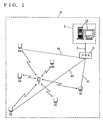
- a mobile terminal 7 is, for example, a PHS terminal that is carried by an employee that works at the building premises 10. Mobile terminal 7 has its physical location altered within the building by being carried by the employee.
- a private PHS network is installed in premises 10 that allows usage of mobile terminal 7 as an extension 2.
- PBX 3 is connected to a private repeater 5 (5A, 5B, 5C ... ) by communication lines 4A, 4B, 4C ... that are arranged indoor of the building of premises 10.
- PBX 3 functions as the control station that coordinates the communication through the extension of mobile terminal 7 via repeaters 5A, 5B, 5C ... .
- an ID transmitter 6 (6A, 6B, 6C ... ) transmitting an ID (identification information) representative thereof is provided independent of the private network including repeaters 5A, 5B, 5C ... .
- a center station 1 functions to identify the position of mobile terminal 7.
- a personal computer 1A used for locating is installed at center station 1.
- the position information corresponding to the position where ID transmitter 6 is installed is prestored in personal computer 1A on an ID-by-ID basis.
- Personal computer 1A is connected to PBX 3 through the extension.
- the received field intensity information output from mobile terminal 7 is applied to personal computer 1A via any of the plurality of repeaters 5A, 5B, 5C ... .
- Mobile terminal 7 identifies each repeater 5 by the repeater identification code transmitted from repeaters 5A, 5B, 5C ... , and constantly monitors the received field intensity of the wave output from each repeater 5.
- a repeater 5 is selected according to the level of the received field intensity to register the call area at PBX 3. By such a procedure, a link channel is established between mobile terminal 7 and control station 3. When there is a communication to or from mobile terminal 7, control is effected to connect the call. As a result, conversation or communication is allowed.
- Mobile terminal 7 selects an appropriate repeater 5 while measuring the received field intensity of each of ID transmitters 6A, 6B, 6C ... .
- Each detected received field intensity is stored internally classified by the ID issued from each of ID transmitters 6A, 6B, 6C ... .
- Mobile terminal 7 also measures the received electric field intensity of repeaters 5A, 5B, 5C ... , and stores internally the detected received field intensity classified by the identification code issued from each of repeaters 5A, 5B, 5C ... .
- the received field intensity of ID transmitter 6 and repeater 5 stored in mobile terminal 7 is altered in accordance with the shift, if any, of mobile terminal 7 within premises 10.
- the staff of center station 1 operates personal computer 1A to send a call to mobile terminal 7. Under control of PBX 3, connection is established between personal computer 1A and mobile terminal 7.
- the present embodiment may be implemented so that a call is automatically sent to mobile terminal 7 at a constant time interval without the operation of the staff of center station 1.
- Mobile terminal 7 transmits the received field intensity information of each of ID transmitters 6A, 6B, 6C ... and each of repeaters 5A, 5B, 5C ... stored internally in response to a request from personal computer 1A.
- the transmitted received field intensity information is input to personal computer 1A via repeater 5 located at the registered call area.
- Position information indicating the location of each of ID transmitters 6A, 6B, 6C ... is stored in personal computer 1A, classified by the ID of ID transmitter 6.
- the position information indicating the location of each of repeaters 5A, 5B, 5C ... is also stored in personal computer 1A, classified by the identification code of repeater 5.
- Personal computer 1A identifies the position of mobile terminal 7 from the input received field intensity information and the internally-stored position information. For example, personal computer 1A identifies the possible location range of mobile terminal 7 from the received field intensity of each of ID transmitters 6A, 6B, 6C ... and each of repeaters 5A, 5B, 5C ... , and then determines the position of mobile terminal 7 by computing the overlapping area of each identified range.
- the identified result of the location of mobile terminal 7 is displayed, for example, on a monitor screen connected to personal computer 1A.
- the position of mobile terminal 7 is indicated to the staff of center station I.
- ID transmitter 6 includes an ID memory unit 65 for storing a predetermined ID, a signal generation unit 64 generating an ID signal according to the ID stored in ID memory unit 65, a modulation unit 63 modulating the ID signal generated by signal generation unit 64, an output unit 62 for providing the ID signal modulated by modulation unit 63, and an antenna unit 61.
- ID transmitter 6 has the function to appropriately arrange the wave among repeaters 5 and among ID transmitters 6. This is required to establish synchronization with the timing of repeater 5. Control is provided so as to allocate the slot of the control channel with the timing of repeaters 5 deviated from each other in a self-isolating manner.
- Signal generation unit 64 continuously generates an ID signal. Therefore, an ID is continuously emitted from antenna unit 61 by a wave of a predetermined frequency and a predetermined transmission output corresponding to the private usage.
- ID transmitter 6 does not have the feature to receive information from mobile terminal 7 and the like. ID transmitter 6 only has the transmitting feature of sending the internally stored ID towards mobile terminal 7. Therefore, ID transmitter 6 can be made more compact and lighter than repeater 5 that is relatively small in size and weight (for example, capacity: 3-10 litters; weight: 3-10 kg). This means that the trouble of installing the facility is not required in this case where the position of mobile terminal 7 is to be identified taking advantage of the received electric field intensity of ID transmitter 6 than of repeater 5. Also, extra area to install the facility will not be required. Furthermore, a line connection unit to connect the wires of communication lines 4A, 4B, 4C ... as for repeater 5 is not required since ID transmitter 6 is absent of the feature of relaying information of mobile terminal 7 as repeater 5.
- ID transmitter 6 structured as described above, the cost of the facility and installation to improve the accuracy of the location can be suppressed by installing many more ID transmitters 6 than in the case of installing more repeaters 5. Furthermore, since the connection of ID transmitter 6 with PBX 3 is dispensable contrary to repeater 5, it is not necessary to increase the extension connection package of the PBX 3 end or replace PBX 3 itself with another type of higher line capacity. By employing ID transmitter 6 affirmatively for position identification, the accuracy of the location can be improved with the cost as low as possible.
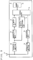
- Fig. 3 is a block diagram showing a structure of mobile terminal 7.
- Mobile terminal 7 includes an antenna unit 71, a reception amplifier 72, a demodulation unit 73, an ID detect unit 74, a control unit 75, a memory unit 76, a received field intensity measurement unit 77, a modulation unit 78, and a transmission amplifier 79.
- the wave issued from ID transmitter 6 is received by antenna unit 71.
- This wave is amplified by reception amplifier 72 and converted into an intermediate frequency to be output to demodulation 73 and received field intensity measurement unit 77.
- Received field intensity measurement unit 77 measures the received field intensity of each ID transmitter 6 according to the output of reception amplifier 72. The result of the measured received field intensity is output to control unit 75.
- Demodulation unit 73 demodulates the output signal of reception amplifier 72. The demodulated signal is applied to ID detect unit 74.
- ID detect unit 74 detects the ID of ID transmitter 6 from the demodulated signal. The detected result is supplied to control unit 75.
- Control unit 75 sequentially stores into memory unit 76 the ID output from ID detect unit 74 and the information of the received field intensity output from received field intensity measurement unit 77 as a pair of received field intensity information.
- the wave issued from each repeater 5 is received on antenna unit 71.
- the wave is amplified by reception amplifier 72 to be provided to demodulation unit 73 and received field intensity measurement unit 77.
- Received field intensity measurement unit 77 measures the received field intensity of each repeater 5 according to that output. The measured result is applied to control unit 75.
- Demodulation unit 73 demodulates the signal output from reception amplifier 72.
- the demodulated signal is applied to ID detect unit 74.
- ID detect unit 74 detects the identification code of repeater 5 according to the signal output from demodulation unit 73.
- the detected result is applied to control unit 75.
- Control unit 75 sequentially stores into memory unit 76 the identification code output from ID detect unit 74 and the received field intensity output from received field intensity measurement unit 77 as one pair of received field intensity information. Control unit 75 selects an appropriate repeater 5 to be used for communication according to the received field intensity information stored in memory unit 76. Then, control unit 75 provides to modulation unit 78 the signal to register the selected repeater 5 to PBX 3 (refer to Fig. 1). The signal provided to modulation unit 78 is modulated into a predetermined high frequency signal. Then, the signal is amplified by transmission amplifier 79 to be output from antenna unit 71.
- Communication between personal computer 1A and mobile terminal 7 is enabled by calling mobile terminal 7 from personal computer 1A (refer to Fig. 1) installed at a remote site.
- Control unit 75 responds to a transmission request of personal computer 1A to provide to modulation unit 78 the received field intensity information (the information pair of the ID and received field intensity of each ID transmitter 6, and the information pair of the identification code and received field intensity of each repeater 5) stored in memory unit 76.
- the received field intensity information is applied to the preselected repeater 5 via modulation unit 78, transmission amplifier 79, and antenna unit 71.
- the information applied to repeater 5 is input to personal computer 1A via PBX 3.
- the position of mobile terminal 7 is identified according to the input received field intensity information.
- Fig. 4 is a flow chart showing the process of ID transmitter 6. Under the condition of the power being turned on (S1), ID transmitter 6 issues the ID stored in ID memory unit 65 (S2). ID transmitter 6 carries out this process repeatedly. Thus, an ID is continuously emitted from ID transmitter 6.
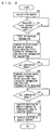
- Fig. 5 is a flow chart showing the process of mobile terminal 7.
- Mobile terminal 7 executes the process set forth in the following repeatedly for every predetermined time.
- the control program required to execute the following process is stored in control unit 75.
- mobile terminal 7 measures the received field intensity of each ID transmitter 6 on an ID-by-ID basis (S11).
- the measured result of the received field intensity of each ID transmitter 6 is stored in memory unit 76, classified by the ID (S12).
- the received field intensity of each repeater 5 is measured on for every different identification code (S13).
- the measured result of the received field intensity of each repeater 5 is stored in memory 76, classified by the identification code (S14).
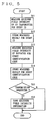
- Fig. 6 is a flow chart showing the process of personal computer 1A.
- the control program required to execute the process set forth in the following is stored in a ROM (Read Only Memory) not shown in personal computer 1A.
- Personal computer 1A is manipulated by the operator to request transmission of received field intensity information to mobile terminal 7 (S20). Determination is made whether received field intensity information is input from mobile terminal 7 (S21). Waiting is conducted until the received field intensity information is input.
- the position information of repeater 5 and the position information of ID transmitter 6 stored in personal computer 1A is called up (S22). Then, the range where mobile terminal 7 can be present is computed according to the received field intensity information of transmitter 6 among the input received field intensity information and the position information of transmitter 6 out of the retrieved position information (S23). This process is carried out for all the received field intensity information corresponding to ID transmitter 6. When the process of S23 ends for all the received field intensity information corresponding to ID transmitter 6, determination of YES is made at S24. Then, the range where mobile terminal 7 can be present is computed according to the position information of repeater 5 and the received field intensity information corresponding to repeater 5 (S25). This process is carried out for all the received field intensity information corresponding to repeater 5. When the process of S25 ends for all the received field intensity information corresponding to repeater 5, determination of YES is made at S26.
- the overlapping area of the computed result of S23 and computed result of S25 is obtained.
- the position of mobile terminal 7 is identified by this computed result (S27). More specifically, the overlapping area out from the computed range of mobile terminal 7 at S23 and S25 is identified as the location of mobile terminal 7.
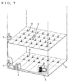
- Fig. 7 shows a structure of ID transmitter 6, mobile terminal 7, and repeater 4 provided in building premises 10.
- Premises 10 is, for example, a building of a plurality of stories.
- ID transmitter 6 is arranged on each floor in a lattice manner.
- the main body of ID transmitter 6 is embedded inside the floor so as to avoid being an obstacle in passage.
- a private repeater 5 for radio communication with mobile terminal 7 is installed at a predetermined site on each floor. Repeater 5 is connected through a private line to PBX 3 located at the basement of the building. Personal computer 1A of center station 1 is connected to the extension channel of PBX 3. Personal computer 1A is configured to identify the position of mobile terminal 7 that is moved throughout the building.
- the position of mobile terminal 7 during movement in a building of a plurality of stories can be supervised at one place in a centralized manner.
- This structure can be utilized in the case where, for example, the foreman of a working party in a construction work wants to acknowledge the location of each worker in a centralized manner by having each worker carry a mobile terminal (PHS terminal) 7 within the premises 10 of the construction work.
- the structure can be utilized in the case where mobile terminal (PHS terminal) 7 is attached to the luggage of a passenger at the premises of an airport to coordinate the luggage.
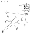
- Fig. 8 shows a structure of the entire system for describing another embodiment of the present invention.
- the present embodiment of Fig. 8 corresponds to the case where the public PHS network is applied.
- Mobile terminal 7 is located at a radio zone (simultaneous calling area) of any of repeater 50 (50A, 50B, 50C ... ) that constitutes the public PHS network.
- the person carrying mobile terminal 7 can communicate through voice and the like using the PHS.
- Repeater 50 is connected to a control station 30 that controls repeater 50 via a communication line 40 (40A, 40B, 40C ... ) of the ISDN.
- a central station 1 is provided remote from mobile terminal 7.
- Personal computer 1A of central station 1 is connected to control station 30 via a public line 20.
- Mobile terminal 7 measures the received field intensity of each of repeaters 50A, 50B, 50C ... and each of ID transmitters 60A, 60B, 60C ... .
- the measured intensity is stored internally, classified by the identification code of each repeater 50 and by the ID of each ID transmitter 60.
- connection between mobile terminal 7 and personal computer 1A is established by control station 30.
- mobile terminal 7 sends the received field intensity information of each repeater 50 and each ID transmitter 60 to the preselected repeater 50. Accordingly, the received field intensity information is applied to personal computer 1A via, for example, the communication channel.
- Personal computer 1A identifies the position of mobile terminal 7 according to the received field intensity information.
- the transmission of the received field intensity information employs the communication channel (traffic channel) in the present embodiment
- a control channel may be used instead. Accordingly, the communication cost can be reduced than the case where the traffic channel is used.
Abstract
Description
- The present invention relates to a location system, a location method, and a mobile terminal. More particularly, the present invention relates to a location system and a location method to identify the position of a mobile terminal that can communicate based on a repeater installed in a radio zone, and such a mobile terminal.
- As an example of a zone communication system that allows communication based on repeaters provided in a plurality of radio zones respectively, a small zone radio communication system such as a PHS (Personal Handyphone System) is known.
- The PHS portable terminal representative of a mobile terminal in a small zone radio communication system is used as a cordless telephone at home. It can also be carried outside to be connected to public and digital networks via indoor or outdoor public repeaters and the like. It can be used literally as a handy portable telephone. The PHS greatly differs from the existing cellular type system in that the PHS employs the small zone system.
- Conventionally, a system of identifying the position of a mobile terminal is proposed according to the received electric field intensity of the radio wave of the repeater in the neighborhood of the mobile terminal that is transmitted therefrom and the identification code of the repeater, taking advantage of the feature that the radio zone of the PHS is of a small area.
- However, there is a limit in the accuracy of identifying the position of the mobile terminal according to the repeater present in a radio zone how small the area may be. In order to improve the accuracy of identifying the position, the radio zone must be made smaller and the number of repeaters increased. However, this causes a great economical burden since the line facility and the like will be required for the repeaters to allow transmission/reception of information with the control station. Furthermore, if the number of repeaters is increased, the load on the control station to coordinate the repeaters becomes heavier to cause the possibility of disabled control.
- In the case of a location system that uses the portable terminal of the PHS employed as a private extension within a building or the like, a possible consideration is to install many private repeaters in the building to improve the accuracy of identifying the position. However, a PBX of a great line capacity will be required as the number of repeaters is increased. There is also the problem that the economical burden is great. Furthermore, the installation cost to connect the line of each repeater to the PBX will be required. Thus, the economical burden will become greater in proportion to the increase in the number of repeaters.
- In view of the foregoing, an object of the present invention is to improve the accuracy of identifying the position of a mobile terminal with the minimum cost.
- According to an aspect of the present invention, a location system for identifying the position of a mobile terminal that can communicate based on a repeater installed in a radio zone, includes: a plurality of transmitter units installed around the mobile terminal apart from the repeater to send transmitter unit identification information that allows identification of each transmitter unit to the mobile terminal by a wave of a predetermined transmission output; a received field intensity measurement unit that can measure the received field intensity at the mobile terminal from the plurality of transmitter units for every different transmitter unit; and a position identify unit identifying the position of the mobile terminal according to the measured result of the received field intensity measurement unit.
- According to another aspect of the present invention, a location method for identifying the position of a mobile terminal that can communicate based on a repeater provided in a radio zone, includes the steps of: sending from a plurality of transmitter units installed around the mobile terminal apart from the repeater transmitter unit identification information that can identify each of the plurality of transmitter units to the mobile terminal by a wave of a predetermined transmission output; measuring the received field intensity at the mobile terminal from the plurality of transmitter units for every different transmitter unit; and identifying the position of the mobile terminal according to the measured received field intensity.
- According to a further aspect of the present invention, a mobile terminal that can communicate based on a repeater provided in a radio zone, includes: a received field intensity measurement unit measuring the received field intensity of a wave sent from a plurality of transmitter units installed around the mobile terminal apart from the repeater for every different transmitter unit; and a memory unit for storing the measured result of the received field intensity measurement unit.
- Thus, the main advantage of the present invention is that a great number of repeaters to improve the accuracy for identifying the position of a mobile terminal does not have to be installed, and that the accuracy of identifying the location can be improved with the minimum cost by taking advantage of the received field intensity of the plurality of transmitter units installed around the mobile terminal apart from the repeater.
- The foregoing and other objects, features, aspects and advantages of the present invention will become more apparent from the following detailed description of the present invention when taken in conjunction with the accompanying drawings.
-
- Fig. 1 is a schematic diagram showing an entire structure of the present system.
- Fig. 2 is a block diagram showing a structure of an
ID transmitter 6. - Fig. 3 is a block diagram showing a structure of a
mobile terminal 7. - Fig. 4 is a flow chart showing the process of
ID transmitter 6. - Fig. 5 is a flow chart showing the process of
mobile terminal 7. - Fig. 6 is a flow chart showing the process of a
personal computer 1A. - Fig. 7 shows a structure of an
ID transmitter 6, amobile terminal 7, and a repeater 4 in thebuilding premises 10. - Fig. 8 shows the structure of the entire system to describe another embodiment of the present invention.
-
- Preferable embodiments of the present invention will be described in detail hereinafter with reference to the drawings.
- Referring to Fig. 1, a
mobile terminal 7 is, for example, a PHS terminal that is carried by an employee that works at thebuilding premises 10.Mobile terminal 7 has its physical location altered within the building by being carried by the employee. - A private PHS network is installed in
premises 10 that allows usage ofmobile terminal 7 as anextension 2.PBX 3 is connected to a private repeater 5 (5A, 5B, 5C ... ) bycommunication lines premises 10.PBX 3 functions as the control station that coordinates the communication through the extension ofmobile terminal 7 viarepeaters - At respective sites on
premises 10, an ID transmitter 6 (6A, 6B, 6C ... ) transmitting an ID (identification information) representative thereof is provided independent of the privatenetwork including repeaters - A
center station 1 functions to identify the position ofmobile terminal 7. Apersonal computer 1A used for locating is installed atcenter station 1. The position information corresponding to the position whereID transmitter 6 is installed is prestored inpersonal computer 1A on an ID-by-ID basis.Personal computer 1A is connected toPBX 3 through the extension. The received field intensity information output frommobile terminal 7 is applied topersonal computer 1A via any of the plurality ofrepeaters - The method of identifying the position of
mobile terminal 7 will be described specifically hereinafter.Mobile terminal 7 identifies eachrepeater 5 by the repeater identification code transmitted fromrepeaters repeater 5. Arepeater 5 is selected according to the level of the received field intensity to register the call area atPBX 3. By such a procedure, a link channel is established betweenmobile terminal 7 andcontrol station 3. When there is a communication to or frommobile terminal 7, control is effected to connect the call. As a result, conversation or communication is allowed. -
Mobile terminal 7 selects anappropriate repeater 5 while measuring the received field intensity of each ofID transmitters ID transmitters Mobile terminal 7 also measures the received electric field intensity ofrepeaters repeaters ID transmitter 6 andrepeater 5 stored inmobile terminal 7 is altered in accordance with the shift, if any, ofmobile terminal 7 withinpremises 10. - The staff of
center station 1 operatespersonal computer 1A to send a call tomobile terminal 7. Under control ofPBX 3, connection is established betweenpersonal computer 1A andmobile terminal 7. The present embodiment may be implemented so that a call is automatically sent tomobile terminal 7 at a constant time interval without the operation of the staff ofcenter station 1.Mobile terminal 7 transmits the received field intensity information of each ofID transmitters repeaters personal computer 1A. The transmitted received field intensity information is input topersonal computer 1A viarepeater 5 located at the registered call area. - Position information indicating the location of each of
ID transmitters personal computer 1A, classified by the ID ofID transmitter 6. The position information indicating the location of each ofrepeaters personal computer 1A, classified by the identification code ofrepeater 5.Personal computer 1A identifies the position ofmobile terminal 7 from the input received field intensity information and the internally-stored position information. For example,personal computer 1A identifies the possible location range ofmobile terminal 7 from the received field intensity of each ofID transmitters repeaters mobile terminal 7 by computing the overlapping area of each identified range. The identified result of the location ofmobile terminal 7 is displayed, for example, on a monitor screen connected topersonal computer 1A. Thus, the position ofmobile terminal 7 is indicated to the staff of center station I. - Fig. 2 is a block diagram showing a structure of
ID transmitter 6.ID transmitter 6 includes anID memory unit 65 for storing a predetermined ID, asignal generation unit 64 generating an ID signal according to the ID stored inID memory unit 65, amodulation unit 63 modulating the ID signal generated bysignal generation unit 64, anoutput unit 62 for providing the ID signal modulated bymodulation unit 63, and anantenna unit 61. Although not shown,ID transmitter 6 has the function to appropriately arrange the wave amongrepeaters 5 and amongID transmitters 6. This is required to establish synchronization with the timing ofrepeater 5. Control is provided so as to allocate the slot of the control channel with the timing ofrepeaters 5 deviated from each other in a self-isolating manner. -
Signal generation unit 64 continuously generates an ID signal. Therefore, an ID is continuously emitted fromantenna unit 61 by a wave of a predetermined frequency and a predetermined transmission output corresponding to the private usage. - As depicted,
ID transmitter 6 does not have the feature to receive information frommobile terminal 7 and the like.ID transmitter 6 only has the transmitting feature of sending the internally stored ID towardsmobile terminal 7. Therefore,ID transmitter 6 can be made more compact and lighter thanrepeater 5 that is relatively small in size and weight (for example, capacity: 3-10 litters; weight: 3-10 kg). This means that the trouble of installing the facility is not required in this case where the position ofmobile terminal 7 is to be identified taking advantage of the received electric field intensity ofID transmitter 6 than ofrepeater 5. Also, extra area to install the facility will not be required. Furthermore, a line connection unit to connect the wires ofcommunication lines repeater 5 is not required sinceID transmitter 6 is absent of the feature of relaying information ofmobile terminal 7 asrepeater 5. - By virtue of
ID transmitter 6 structured as described above, the cost of the facility and installation to improve the accuracy of the location can be suppressed by installing manymore ID transmitters 6 than in the case of installingmore repeaters 5. Furthermore, since the connection ofID transmitter 6 withPBX 3 is dispensable contrary torepeater 5, it is not necessary to increase the extension connection package of thePBX 3 end or replacePBX 3 itself with another type of higher line capacity. By employingID transmitter 6 affirmatively for position identification, the accuracy of the location can be improved with the cost as low as possible. - Fig. 3 is a block diagram showing a structure of
mobile terminal 7.Mobile terminal 7 includes anantenna unit 71, areception amplifier 72, ademodulation unit 73, an ID detectunit 74, acontrol unit 75, amemory unit 76, a received fieldintensity measurement unit 77, amodulation unit 78, and atransmission amplifier 79. - The wave issued from
ID transmitter 6 is received byantenna unit 71. This wave is amplified byreception amplifier 72 and converted into an intermediate frequency to be output todemodulation 73 and received fieldintensity measurement unit 77. - Received field
intensity measurement unit 77 measures the received field intensity of eachID transmitter 6 according to the output ofreception amplifier 72. The result of the measured received field intensity is output to controlunit 75.Demodulation unit 73 demodulates the output signal ofreception amplifier 72. The demodulated signal is applied to ID detectunit 74. ID detectunit 74 detects the ID ofID transmitter 6 from the demodulated signal. The detected result is supplied to controlunit 75. -
Control unit 75 sequentially stores intomemory unit 76 the ID output from ID detectunit 74 and the information of the received field intensity output from received fieldintensity measurement unit 77 as a pair of received field intensity information. - The wave issued from each
repeater 5 is received onantenna unit 71. Upon reception of the wave fromrepeater 5, the wave is amplified byreception amplifier 72 to be provided todemodulation unit 73 and received fieldintensity measurement unit 77. Received fieldintensity measurement unit 77 measures the received field intensity of eachrepeater 5 according to that output. The measured result is applied to controlunit 75.Demodulation unit 73 demodulates the signal output fromreception amplifier 72. The demodulated signal is applied to ID detectunit 74. ID detectunit 74 detects the identification code ofrepeater 5 according to the signal output fromdemodulation unit 73. The detected result is applied to controlunit 75.Control unit 75 sequentially stores intomemory unit 76 the identification code output from ID detectunit 74 and the received field intensity output from received fieldintensity measurement unit 77 as one pair of received field intensity information.Control unit 75 selects anappropriate repeater 5 to be used for communication according to the received field intensity information stored inmemory unit 76. Then, controlunit 75 provides tomodulation unit 78 the signal to register the selectedrepeater 5 to PBX 3 (refer to Fig. 1). The signal provided tomodulation unit 78 is modulated into a predetermined high frequency signal. Then, the signal is amplified bytransmission amplifier 79 to be output fromantenna unit 71. - Communication between
personal computer 1A andmobile terminal 7 is enabled by callingmobile terminal 7 frompersonal computer 1A (refer to Fig. 1) installed at a remote site.Control unit 75 responds to a transmission request ofpersonal computer 1A to provide tomodulation unit 78 the received field intensity information (the information pair of the ID and received field intensity of eachID transmitter 6, and the information pair of the identification code and received field intensity of each repeater 5) stored inmemory unit 76. Accordingly, the received field intensity information is applied to the preselectedrepeater 5 viamodulation unit 78,transmission amplifier 79, andantenna unit 71. The information applied torepeater 5 is input topersonal computer 1A viaPBX 3. Atpersonal computer 1A, the position ofmobile terminal 7 is identified according to the input received field intensity information. - Fig. 4 is a flow chart showing the process of
ID transmitter 6. Under the condition of the power being turned on (S1),ID transmitter 6 issues the ID stored in ID memory unit 65 (S2).ID transmitter 6 carries out this process repeatedly. Thus, an ID is continuously emitted fromID transmitter 6. - Fig. 5 is a flow chart showing the process of
mobile terminal 7.Mobile terminal 7 executes the process set forth in the following repeatedly for every predetermined time. The control program required to execute the following process is stored incontrol unit 75. - First,
mobile terminal 7 measures the received field intensity of eachID transmitter 6 on an ID-by-ID basis (S11). The measured result of the received field intensity of eachID transmitter 6 is stored inmemory unit 76, classified by the ID (S12). Then, the received field intensity of eachrepeater 5 is measured on for every different identification code (S13). The measured result of the received field intensity of eachrepeater 5 is stored inmemory 76, classified by the identification code (S14). - Then, determination is made whether there is a transmission request from
personal computer 1A (S15). The process ends when determination is made that there is no transmission request frompersonal computer 1A. In the case where the process ends because there is no transmission request frompersonal computer 1A, the process from S11 is carried out repeatedly. - In the case where determination is made that there is a transmission request from
personal computer 1A at S15, the received field intensity information ofID transmitter 6 andrepeater 5 stored inmemory unit 76 is transmitted topersonal computer 1A (S16). Then, the process ends. Next, the process from S11 is carried out again repeatedly. - Fig. 6 is a flow chart showing the process of
personal computer 1A. The control program required to execute the process set forth in the following is stored in a ROM (Read Only Memory) not shown inpersonal computer 1A. -
Personal computer 1A is manipulated by the operator to request transmission of received field intensity information to mobile terminal 7 (S20). Determination is made whether received field intensity information is input from mobile terminal 7 (S21). Waiting is conducted until the received field intensity information is input. - Upon input of received field intensity information from
mobile terminal 7, the position information ofrepeater 5 and the position information ofID transmitter 6 stored inpersonal computer 1A is called up (S22). Then, the range wheremobile terminal 7 can be present is computed according to the received field intensity information oftransmitter 6 among the input received field intensity information and the position information oftransmitter 6 out of the retrieved position information (S23). This process is carried out for all the received field intensity information corresponding toID transmitter 6. When the process of S23 ends for all the received field intensity information corresponding toID transmitter 6, determination of YES is made at S24. Then, the range wheremobile terminal 7 can be present is computed according to the position information ofrepeater 5 and the received field intensity information corresponding to repeater 5 (S25). This process is carried out for all the received field intensity information corresponding torepeater 5. When the process of S25 ends for all the received field intensity information corresponding torepeater 5, determination of YES is made at S26. - Then, the overlapping area of the computed result of S23 and computed result of S25 is obtained. The position of
mobile terminal 7 is identified by this computed result (S27). More specifically, the overlapping area out from the computed range ofmobile terminal 7 at S23 and S25 is identified as the location ofmobile terminal 7. - Then, the identified position of
mobile terminal 7 is displayed on the monitor ofpersonal computer 1A (S28). - Fig. 7 shows a structure of
ID transmitter 6,mobile terminal 7, and repeater 4 provided in buildingpremises 10.Premises 10 is, for example, a building of a plurality of stories.ID transmitter 6 is arranged on each floor in a lattice manner. The main body ofID transmitter 6 is embedded inside the floor so as to avoid being an obstacle in passage. - A
private repeater 5 for radio communication withmobile terminal 7 is installed at a predetermined site on each floor.Repeater 5 is connected through a private line toPBX 3 located at the basement of the building.Personal computer 1A ofcenter station 1 is connected to the extension channel ofPBX 3.Personal computer 1A is configured to identify the position ofmobile terminal 7 that is moved throughout the building. - According to the illustrated structure, the position of
mobile terminal 7 during movement in a building of a plurality of stories can be supervised at one place in a centralized manner. This structure can be utilized in the case where, for example, the foreman of a working party in a construction work wants to acknowledge the location of each worker in a centralized manner by having each worker carry a mobile terminal (PHS terminal) 7 within thepremises 10 of the construction work. Alternatively, the structure can be utilized in the case where mobile terminal (PHS terminal) 7 is attached to the luggage of a passenger at the premises of an airport to coordinate the luggage. - Fig. 8 shows a structure of the entire system for describing another embodiment of the present invention. In contrast to the embodiment of the Fig. 1 that uses a private PHS network, the present embodiment of Fig. 8 corresponds to the case where the public PHS network is applied.
-
Mobile terminal 7 is located at a radio zone (simultaneous calling area) of any of repeater 50 (50A, 50B, 50C ... ) that constitutes the public PHS network. The person carryingmobile terminal 7 can communicate through voice and the like using the PHS. Repeater 50 is connected to acontrol station 30 that controls repeater 50 via a communication line 40 (40A, 40B, 40C ... ) of the ISDN. Also, acentral station 1 is provided remote frommobile terminal 7.Personal computer 1A ofcentral station 1 is connected to controlstation 30 via apublic line 20. -
Mobile terminal 7 measures the received field intensity of each ofrepeaters ID transmitters 60A, 60B, 60C ... . The measured intensity is stored internally, classified by the identification code of each repeater 50 and by the ID of each ID transmitter 60. - By transmission of the public line number of
mobile terminal 7 frompersonal computer 1A subsequent to the specification of an appropriate repeater 50 as the call area according to the measured result of the received field intensity frommobile terminal 7, connection betweenmobile terminal 7 andpersonal computer 1A is established bycontrol station 30. At the stage where communication withpersonal computer 1A is enabled,mobile terminal 7 sends the received field intensity information of each repeater 50 and each ID transmitter 60 to the preselected repeater 50. Accordingly, the received field intensity information is applied topersonal computer 1A via, for example, the communication channel.Personal computer 1A identifies the position ofmobile terminal 7 according to the received field intensity information. - Although the transmission of the received field intensity information employs the communication channel (traffic channel) in the present embodiment, a control channel may be used instead. Accordingly, the communication cost can be reduced than the case where the traffic channel is used.
- Modifications of the above-described embodiment are set forth in the following.
- (1) As a specific example of
ID transmitter 6, the general PHS cordless base unit that is popular domestically can be considered. The PHS cordless base unit allows the PHS terminal to be used as a remote unit of the telephone set connected to the general subscriber telephone line. By registering the PHS terminal and the telephone set to this PHS cordless base unit, a call to the telephone set via the general subscriber telephone line is transferred by the relay feature of the PHS cordless base unit to the preregistered PHS terminal. By using such an existing PHS cordless base unit, the cost and trouble to prepare and install adedicated ID transmitter 6 can be eliminated. Particularly, it is noted that the cost of aprivate repeater 5 is approximately a hundred and several ten thousand Japanese yen whereas the actual price of a PHS cordless base unit is less than ten thousand yen. By using the PHS cordless base unit functioning as an ID transmitter together withrepeater 5 for the purpose of identifying the position ofmobile terminal 7, the accuracy of location can be improved more economically.It is to be noted that the PHS cordless base unit utilizes a frequency range identical to that ofprivate repeater 5 arranged in the private PHS network. In an area where both theprivate repeater 5 and the PHS cordless base unit are installed, the received field intensity of both theprivate repeater 5 and the PHS cordless base unit can be obtained together by measuring the received field intensity of the wave of one frequency range. - (2) In the present embodiment, the received field intensity
information from
mobile terminal 7 is sent topersonal computer 1A in response to an instruction frompersonal computer 1A. A structure can be implemented in which the receive field intensity information is transmitted periodically from the end ofmobile terminal 7. - (3) In the present embodiment, the position of
mobile terminal 7 is identified by using together the received field intensity ofrepeater 5 and the received field intensity ofID transmitter 6. A structure may be implemented in which the received field intensity ofrepeater 5 is not used for locating, and the position ofmobile terminal 7 is identified according to solely the received field intensity ofID transmitter 6. By increasing the number ofID transmitters 6 installed,mobile terminal 7 can be located at a level of accuracy high enough without using the received field intensity ofrepeater 5. - (4)
Mobile terminal 7 can be configured to include position information, and carry out the computation for position identification. The result of the identified position (for example, coordinates and the like) can be sent topersonal computer 1A. -
- Although the present invention has been described and illustrated in detail, it is clearly understood that the same is by way of illustration and example only and is not to be taken by way of limitation, the spirit and scope of the present invention being limited only by the terms of the appended claims.
Claims (10)
- A location system for identifying the position of a mobile terminal (7) that can communicate based on a repeater (5) provided at a radio zone, comprising:a plurality of transmitter means (6, 6A, 6B, 6C, 60A, 60B, 60C) installed around said mobile terminal (7) apart from said repeater (5), for sending transmitter means identification information that allows identification of each transmitter means to said mobile terminal (7) by a wave of a predetermined transmission output,received field intensity measurement means (77) that can measure received field intensity of said plurality of transmitter means (6, 6A, 6B, 6C, 60A, 60B, 60C) at said mobile terminal (7) for every different transmitter means (6, 6A, 6B, 6C, 60A, 60B, 60C), andposition identify means (1A) for identifying the position of said mobile terminal (7) according to a measured result of said received field intensity measurement means (77).
- The location system according to claim 1, wherein said received field intensity measurement means (77) can measure received field intensity of a plurality of repeaters (5, 5A, 5B, 5C, 50A, 50B, 50C) installed around said mobile terminal (7) at said mobile terminal (7) for every different repeater (5, 5A, 5B, 5C, 50A, 50B, 50C),
wherein said position identify means (1A) identifies the position of said mobile terminal (7) according to the measured result of the received field intensity for every different transmitter means (6, 6A, 6B, 6C, 60A, 60B, 60C) and the measured result of the received field intensity for every different repeater (5, 5A, 5B, 5C, 50A, 50B, 50C). - The location system according to claim 1 or 2, further comprising transmission means (71, 78, 79) for sending a measured result of said received field intensity measurement means (77) to said position identification means (1A).
- The location system according to one of claims 1 to 3, wherein said repeater (5) is a repeater (5) in a personal handyphone system.
- A location method for identifying the position of a mobile terminal (7) that can communicate based on a repeater (5) provided in a radio zone, comprising:a step (S2) of sending from a plurality of transmitter means (6, 6A, 6B, 6C, 60A, 60B, 60C) installed around said mobile terminal (7) apart from said repeater (5) transmitter means identification information that allows identification of each transmitter means to said mobile terminal (7) by a wave of a predetermined transmission output,a step (S11) of measuring received field intensity of said plurality of transmitter means (6, 6A, 6B, 6C, 60A, 60B, 60C) at said mobile terminal (7) for every different transmitter means (6, 6A, 6B, 6C, 60A, 60B, 60C), anda step (S21-S24, S27) of identifying the position of said mobile terminal (7) according to the measured received field intensity.
- The location method according to claim 5, further comprising:a step (S13) of measuring received field intensity of a plurality of repeaters (5, 5A, 5B, 5C, 50A, 50B, 50C) installed around said mobile terminal (7) for every different repeater (5, 5A, 5B, 5C, 50A, 50B, 50C), anda step (S21-S27) of identifying the position of said mobile terminal (7) according to a measured result of the received field intensity for every different transmitter means (6, 6A, 6B, 6C, 60A, 60B, 60C) and a measured result of the received field intensity for every different repeater (5, 5A, 5B, 5C, 50A, 50B, 50C).
- A mobile terminal (7) that can communicate based on a repeater (5) provided in a radio zone, comprising:received field intensity measurement means (77) for measuring received field intensity of a wave sent from a plurality of transmitter means (6, 6A, 6B, 6C, 60A, 60B, 60C) installed around said mobile terminal (7) apart from said repeater (5) for every different transmitter means (6, 6A, 6B, 6C, 60A, 60B, 60C), andmemory means (76) for storing a measured result of said received field intensity measurement means (77).
- The mobile terminal (7) according to claim 7, wherein said received field intensity measurement means (77) can measure the received field intensity of a wave sent from a plurality of repeaters (5, 5A, 5B, 5C, 50A, 50B, 50C) installed around said mobile terminal (7) for every different repeater (5, 5A, 5B, 5C, 50A, 50B, 50C), and
wherein said memory means (76) stores the received field intensity for every different transmitter means (6, 6A, 6B, 6C, 60A, 60B, 60C) and the received field intensity for every different repeater (5, 5A, 5B, 5C, 50A, 50B, 50C) measured by said received field intensity measurement means (77). - The mobile terminal (7) according to claim 7 or 8, further comprising transmission means (71, 78, 79) for transmitting a measured result of said received field intensity measurement means (77).
- The mobile terminal (7) according to one of claims 7 to 9, wherein said mobile terminal (7) is a terminal (7) used in a personal handyphone system.
Applications Claiming Priority (2)
| Application Number | Priority Date | Filing Date | Title |
|---|---|---|---|
| JP554798 | 1998-01-14 | ||
| JP10005547A JPH11205845A (en) | 1998-01-14 | 1998-01-14 | Position specifying system |
Publications (2)
| Publication Number | Publication Date |
|---|---|
| EP0930514A2 true EP0930514A2 (en) | 1999-07-21 |
| EP0930514A3 EP0930514A3 (en) | 2000-09-27 |
Family
ID=11614226
Family Applications (1)
| Application Number | Title | Priority Date | Filing Date |
|---|---|---|---|
| EP98124879A Ceased EP0930514A3 (en) | 1998-01-14 | 1998-12-30 | System and method for identifying position of mobile terminal |
Country Status (5)
| Country | Link |
|---|---|
| US (1) | US6415155B1 (en) |
| EP (1) | EP0930514A3 (en) |
| JP (1) | JPH11205845A (en) |
| KR (1) | KR19990067886A (en) |
| SG (1) | SG97776A1 (en) |
Cited By (49)
| Publication number | Priority date | Publication date | Assignee | Title |
|---|---|---|---|---|
| WO2000050919A2 (en) * | 1999-02-25 | 2000-08-31 | Microsoft Corporation | Method and computer-readable medium for locating and tracking a user in a wireless network using a table of dignal data |
| WO2001031966A1 (en) * | 1999-10-29 | 2001-05-03 | Cellpoint Systems Ab | Method and arrangement relating to positioning |
| EP1111951A2 (en) * | 1999-12-21 | 2001-06-27 | Nortel Networks Limited | Wireless access systems and method of portable device location therein |
| US6393294B1 (en) | 1998-09-22 | 2002-05-21 | Polaris Wireless, Inc. | Location determination using RF fingerprinting |
| FR2822610A1 (en) * | 2001-03-26 | 2002-09-27 | Sagem | Mobile telephone positioning process having base station power levels measured/compared determining zone then beacon power levels found providing more accurate positioning. |
| WO2002085057A1 (en) * | 2001-04-06 | 2002-10-24 | Nokia Corporation | Location method and system |
| EP1303155A1 (en) * | 2001-10-12 | 2003-04-16 | Ascom Tateco Ab | System, method and device for determining the position of a portable device in a wireless communication system |
| EP1316897A1 (en) * | 2000-08-07 | 2003-06-04 | Sharp Kabushiki Kaisha | Server apparatus for processing information according to information about position of terminal |
| WO2003058986A2 (en) * | 2001-12-27 | 2003-07-17 | Qualcomm, Incorporated | Creating and using base station almanac information in a wireless communication system having a position location capability |
| EP1359714A2 (en) * | 2002-05-02 | 2003-11-05 | Microsoft Corporation | Method and system for determining the location of a mobile computer |
| DE10215725A1 (en) * | 2002-04-10 | 2003-11-13 | Koepenick Funkwerk Gmbh | Radio location system in trunked digital radio networks has digital trunked radio network, location regions in network, each with at least 2 radio beacons, trunked radio network users' mobile devices |
| WO2004004399A1 (en) * | 2002-06-28 | 2004-01-08 | Nokia Corporation | Location sevice support for distributed bts architecture |
| WO2004014096A1 (en) * | 2002-07-31 | 2004-02-12 | Koninklijke Philips Electronics N.V. | System for locating a mobile unit |
| WO2004049632A1 (en) * | 2002-11-27 | 2004-06-10 | Koninklijke Philips Electronics N.V. | Positioning method, system and unit |
| US6799047B1 (en) | 1999-02-25 | 2004-09-28 | Microsoft Corporation | Locating and tracking a user in a wireless network through environmentally profiled data |
| US6839560B1 (en) | 1999-02-25 | 2005-01-04 | Microsoft Corporation | Using a derived table of signal strength data to locate and track a user in a wireless network |
| WO2005032202A1 (en) * | 2003-10-02 | 2005-04-07 | Telefonaktiebolaget Lm Ericsson (Publ) | Method for position determination of mobile stations |
| WO2005031383A1 (en) * | 2003-09-27 | 2005-04-07 | Koninklijke Philips Electronics N.V. | Network for locating a wireless tag |
| US6990428B1 (en) | 2003-07-28 | 2006-01-24 | Cisco Technology, Inc. | Radiolocation using path loss data |
| WO2006090258A1 (en) * | 2005-02-25 | 2006-08-31 | Nokia Corporation | Location services in a communications system |
| US7116988B2 (en) | 2004-03-16 | 2006-10-03 | Airespace, Inc. | Location of wireless nodes using signal strength weighting metric |
| US7205938B2 (en) | 2004-03-05 | 2007-04-17 | Airespace, Inc. | Wireless node location mechanism responsive to observed propagation characteristics of wireless network infrastructure signals |
| US7260408B2 (en) | 2004-02-20 | 2007-08-21 | Airespace, Inc. | Wireless node location mechanism using antenna pattern diversity to enhance accuracy of location estimates |
| US7286835B1 (en) | 2004-09-10 | 2007-10-23 | Airespace, Inc. | Enhanced wireless node location using differential signal strength metric |
| US7286833B2 (en) | 2004-02-27 | 2007-10-23 | Airespace, Inc. | Selective termination of wireless connections to refresh signal information in wireless node location infrastructure |
| US7286515B2 (en) | 2003-07-28 | 2007-10-23 | Cisco Technology, Inc. | Method, apparatus, and software product for detecting rogue access points in a wireless network |
| US7293088B2 (en) | 2003-07-28 | 2007-11-06 | Cisco Technology, Inc. | Tag location, client location, and coverage hole location in a wireless network |
| US7336670B1 (en) | 2003-06-30 | 2008-02-26 | Airespace, Inc. | Discovery of rogue access point location in wireless network environments |
| WO2008022575A1 (en) * | 2006-08-16 | 2008-02-28 | Huawei Technologies Co., Ltd. | A method and device for enhancing positioning user equipment |
| US7342906B1 (en) | 2003-04-04 | 2008-03-11 | Airespace, Inc. | Distributed wireless network security system |
| US7346338B1 (en) | 2003-04-04 | 2008-03-18 | Airespace, Inc. | Wireless network system including integrated rogue access point detection |
| CN100381007C (en) * | 2002-06-21 | 2008-04-09 | 诺基亚公司 | Signal path detection for wireless networks including repeaters |
| US7370362B2 (en) | 2005-03-03 | 2008-05-06 | Cisco Technology, Inc. | Method and apparatus for locating rogue access point switch ports in a wireless network |
| US7433696B2 (en) | 2004-05-18 | 2008-10-07 | Cisco Systems, Inc. | Wireless node location mechanism featuring definition of search region to optimize location computation |
| US7489661B2 (en) | 2003-04-04 | 2009-02-10 | Cisco Systems, Inc. | Dynamic transmit power configuration system for wireless network environments |
| US7516174B1 (en) | 2004-11-02 | 2009-04-07 | Cisco Systems, Inc. | Wireless network security mechanism including reverse network address translation |
| US7539169B1 (en) | 2003-06-30 | 2009-05-26 | Cisco Systems, Inc. | Directed association mechanism in wireless network environments |
| US7596376B2 (en) | 2005-02-18 | 2009-09-29 | Cisco Technology, Inc. | Methods, apparatuses and systems facilitating client handoffs in wireless network systems |
| EP2192706A2 (en) | 2006-09-15 | 2010-06-02 | Itron, Inc. | Embedded RF environmental evaluation |
| US7805140B2 (en) | 2005-02-18 | 2010-09-28 | Cisco Technology, Inc. | Pre-emptive roaming mechanism allowing for enhanced QoS in wireless network environments |
| US7821986B2 (en) | 2006-05-31 | 2010-10-26 | Cisco Technology, Inc. | WLAN infrastructure provided directions and roaming |
| US8478228B2 (en) | 2008-10-20 | 2013-07-02 | Qualcomm Incorporated | Mobile receiver with location services capability |
| US8532567B2 (en) | 2003-07-21 | 2013-09-10 | Qualcomm Incorporated | Method and apparatus for creating and using a base station almanac for position determination |
| US8600297B2 (en) | 2009-07-28 | 2013-12-03 | Qualcomm Incorporated | Method and system for femto cell self-timing and self-locating |
| DE102012214190A1 (en) * | 2012-08-09 | 2014-02-13 | Siemens Convergence Creators Gmbh | Method for determining position of moving object i.e. persons, in inner area environment e.g. tunnel, involves assigning signal sources to distribution assemblies, and deriving position of object from combination of values and signal |
| US9137771B2 (en) | 2004-04-02 | 2015-09-15 | Qualcomm Incorporated | Methods and apparatuses for beacon assisted position determination systems |
| US9756599B2 (en) | 2015-05-12 | 2017-09-05 | Qualcomm Incorporated | Positioning reference signal (PRS) generation for multiple transmit antenna systems |
| EP3299837A1 (en) * | 2016-09-27 | 2018-03-28 | TP Vision Holding B.V. | Proximity detection method |
| US9986526B2 (en) | 2009-06-26 | 2018-05-29 | Qualcomm Incorporated | Positioning in the presence of passive distributed elements |
Families Citing this family (46)
| Publication number | Priority date | Publication date | Assignee | Title |
|---|---|---|---|---|
| US8982856B2 (en) | 1996-12-06 | 2015-03-17 | Ipco, Llc | Systems and methods for facilitating wireless network communication, satellite-based wireless network systems, and aircraft-based wireless network systems, and related methods |
| US7054271B2 (en) | 1996-12-06 | 2006-05-30 | Ipco, Llc | Wireless network system and method for providing same |
| JPH11328564A (en) * | 1998-05-15 | 1999-11-30 | Nec Commun Syst Ltd | Private branch exchange system with position display function |
| US6891838B1 (en) * | 1998-06-22 | 2005-05-10 | Statsignal Ipc, Llc | System and method for monitoring and controlling residential devices |
| US8410931B2 (en) | 1998-06-22 | 2013-04-02 | Sipco, Llc | Mobile inventory unit monitoring systems and methods |
| US6914893B2 (en) | 1998-06-22 | 2005-07-05 | Statsignal Ipc, Llc | System and method for monitoring and controlling remote devices |
| US6437692B1 (en) | 1998-06-22 | 2002-08-20 | Statsignal Systems, Inc. | System and method for monitoring and controlling remote devices |
| US7650425B2 (en) | 1999-03-18 | 2010-01-19 | Sipco, Llc | System and method for controlling communication between a host computer and communication devices associated with remote devices in an automated monitoring system |
| EP1056306B1 (en) * | 1999-05-26 | 2006-10-11 | Sony Deutschland GmbH | Geolocation determination |
| JP2001255365A (en) * | 2000-03-13 | 2001-09-21 | Matsushita Electric Ind Co Ltd | Detection system for position of mobile station |
| US20010036832A1 (en) * | 2000-04-14 | 2001-11-01 | Onscene, Inc. | Emergency command and control system |
| GB0011643D0 (en) * | 2000-05-16 | 2000-07-05 | Hewlett Packard Co | Retrieval of location-related information |
| GB0012143D0 (en) | 2000-05-20 | 2000-07-12 | Hewlett Packard Co | Obtaining location updates about mobile entity for use in a location-sensitive application |
| GB0012445D0 (en) * | 2000-05-24 | 2000-07-12 | Hewlett Packard Co | Location-based equipment control |
| GB0012749D0 (en) * | 2000-05-26 | 2000-07-19 | Hewlett Packard Co | Finding locally-relevant information in a physical document |
| US6735444B2 (en) * | 2000-12-21 | 2004-05-11 | Telefonaktiebolaget Lm Ericsson (Publ) | Method and system for locating a device using a local wireless link |
| US7139580B2 (en) * | 2001-04-24 | 2006-11-21 | Qualcomm Incorporated | Method and apparatus for estimating the position of a terminal based on identification codes for transmission sources |
| US6873851B2 (en) * | 2001-05-03 | 2005-03-29 | International Business Machines Corporation | Method, system, and program for providing user location information for a personal information management system from transmitting devices |
| US6915135B1 (en) * | 2001-05-15 | 2005-07-05 | Praxis Technology Group, Inc. | Method and system for detecting object presence and its duration in a given area |
| JP2003114952A (en) * | 2001-10-09 | 2003-04-18 | Nippon Telegr & Teleph Corp <Ntt> | Communication system |
| US8489063B2 (en) | 2001-10-24 | 2013-07-16 | Sipco, Llc | Systems and methods for providing emergency messages to a mobile device |
| US7480501B2 (en) | 2001-10-24 | 2009-01-20 | Statsignal Ipc, Llc | System and method for transmitting an emergency message over an integrated wireless network |
| US7424527B2 (en) | 2001-10-30 | 2008-09-09 | Sipco, Llc | System and method for transmitting pollution information over an integrated wireless network |
| WO2003044970A2 (en) * | 2001-11-20 | 2003-05-30 | Qualcomm Incorporated | Reverse link power controlled repeater |
| US7831263B2 (en) * | 2002-11-08 | 2010-11-09 | Qualcomm Incorporated | Apparatus and method for determining the location of a repeater |
| US7047020B2 (en) * | 2003-07-16 | 2006-05-16 | Qualcomm Inc. | Assistance techniques for subscriber units having positioning capabilities |
| US7212798B1 (en) | 2003-07-17 | 2007-05-01 | Cisco Technology, Inc. | Adaptive AGC in a wireless network receiver |
| KR100562228B1 (en) * | 2004-02-23 | 2006-03-22 | 에스케이 텔레콤주식회사 | Method and System for Determining Position of Mobile Communication Terminal by Using Specific Paging Channel in ???? Mobile Communication Network |
| US8031650B2 (en) | 2004-03-03 | 2011-10-04 | Sipco, Llc | System and method for monitoring remote devices with a dual-mode wireless communication protocol |
| US7756086B2 (en) | 2004-03-03 | 2010-07-13 | Sipco, Llc | Method for communicating in dual-modes |
| US9118380B2 (en) * | 2004-04-05 | 2015-08-25 | Qualcomm Incorporated | Repeater with positioning capabilities |
| JP2007532079A (en) * | 2004-04-05 | 2007-11-08 | クゥアルコム・インコーポレイテッド | A repeater that reports detected neighbors |
| US7778596B2 (en) | 2004-07-29 | 2010-08-17 | Qualcomm Incorporated | Airlink sensing watermarking repeater |
| WO2006081206A1 (en) | 2005-01-25 | 2006-08-03 | Sipco, Llc | Wireless network protocol systems and methods |
| GB2449278B (en) * | 2007-05-16 | 2009-10-07 | Multitone Electronics Plc | Telecommunications system and method |
| AU2007274018B2 (en) * | 2006-07-14 | 2011-02-03 | Multitone Electronics Plc | Telecommunications system and method |
| US7835749B1 (en) | 2006-10-03 | 2010-11-16 | Cisco Technology, Inc. | Location inspector in wireless networks |
| US7616555B2 (en) * | 2006-10-03 | 2009-11-10 | Cisco Technology, Inc. | Minimum variance location estimation in wireless networks |
| US7626969B2 (en) * | 2006-10-04 | 2009-12-01 | Cisco Technology, Inc. | Relative location of a wireless node in a wireless network |
| US7983667B2 (en) | 2006-10-05 | 2011-07-19 | Cisco Technology, Inc. | Radio frequency coverage map generation in wireless networks |
| US7904092B2 (en) * | 2007-01-04 | 2011-03-08 | Cisco Technology, Inc. | Locally adjusted radio frequency coverage maps in wireless networks |
| KR101454021B1 (en) * | 2007-08-07 | 2014-10-27 | 삼성전자주식회사 | Apparatus and method for measuring home cell/private networks in mobile communication system |
| JP4974378B2 (en) | 2007-12-28 | 2012-07-11 | アズビル株式会社 | Unique information setting system and unique information setting device |
| US8077031B2 (en) * | 2009-08-20 | 2011-12-13 | Consortium P, Inc. | Position locating by polyhedral morphing |
| KR101294864B1 (en) * | 2011-10-17 | 2013-08-23 | (주)텔레필드 | Device and method for changing position of optical transmitter in visible light communication systems |
| CN110998355A (en) * | 2017-08-08 | 2020-04-10 | 日本电产株式会社 | Mobile positioning system and logistics management system |
Citations (4)
| Publication number | Priority date | Publication date | Assignee | Title |
|---|---|---|---|---|
| GB2304250A (en) * | 1995-08-12 | 1997-03-12 | Nat Vulcan Safety Products Ltd | Tracking a moveable object |
| US5613205A (en) * | 1995-03-31 | 1997-03-18 | Telefonaktiebolaget Lm Ericsson | System and method of locating a mobile terminal within the service area of a cellular telecommunication system |
| WO1997033386A1 (en) * | 1996-03-05 | 1997-09-12 | Matsushita Electric Industrial Co., Ltd. | System for detecting positional information |
| EP0814627A2 (en) * | 1995-07-25 | 1997-12-29 | Ace K Computer Co., Ltd. | Position display system of mobile terminal |
Family Cites Families (8)
| Publication number | Priority date | Publication date | Assignee | Title |
|---|---|---|---|---|
| DE69321268T2 (en) * | 1992-01-20 | 1999-05-20 | Nec Corp | Personal localization system |
| JPH06213991A (en) | 1993-01-14 | 1994-08-05 | Fujitsu Ltd | Detection and calibration method for zone slip in decker navigator system |
| FR2715013B1 (en) * | 1994-01-12 | 1996-03-29 | Nortel Matra Cellular | Method for locating a mobile cellular radio station, and equipment for implementing the method. |
| US5724660A (en) * | 1995-06-07 | 1998-03-03 | At&T Wireless Services, Inc. | Method and apparatus for locating a mobile station by comparing calculated location area with GPS coordinates |
| JPH09171070A (en) | 1995-12-20 | 1997-06-30 | Fujitsu General Ltd | Position measuring system |
| GB2311697B (en) * | 1996-03-22 | 1999-07-28 | Matsushita Electric Ind Co Ltd | Wireless communication system and method and system for detection of position of radio mobile station |
| JPH1047982A (en) * | 1996-08-06 | 1998-02-20 | Sony Corp | Instrument and method for measuring location, device and method for navigation, information service method, and automobile |
| US6055434A (en) * | 1997-02-11 | 2000-04-25 | Ericsson Inc. | Method and system for locating a mobile station within a mobile telecommunications network |
-
1998
- 1998-01-14 JP JP10005547A patent/JPH11205845A/en not_active Withdrawn
- 1998-12-24 SG SG9805958A patent/SG97776A1/en unknown
- 1998-12-30 EP EP98124879A patent/EP0930514A3/en not_active Ceased
-
1999
- 1999-01-05 US US09/225,544 patent/US6415155B1/en not_active Expired - Fee Related
- 1999-01-13 KR KR1019990000729A patent/KR19990067886A/en active IP Right Grant
Patent Citations (4)
| Publication number | Priority date | Publication date | Assignee | Title |
|---|---|---|---|---|
| US5613205A (en) * | 1995-03-31 | 1997-03-18 | Telefonaktiebolaget Lm Ericsson | System and method of locating a mobile terminal within the service area of a cellular telecommunication system |
| EP0814627A2 (en) * | 1995-07-25 | 1997-12-29 | Ace K Computer Co., Ltd. | Position display system of mobile terminal |
| GB2304250A (en) * | 1995-08-12 | 1997-03-12 | Nat Vulcan Safety Products Ltd | Tracking a moveable object |
| WO1997033386A1 (en) * | 1996-03-05 | 1997-09-12 | Matsushita Electric Industrial Co., Ltd. | System for detecting positional information |
Cited By (79)
| Publication number | Priority date | Publication date | Assignee | Title |
|---|---|---|---|---|
| US7725111B2 (en) | 1998-09-22 | 2010-05-25 | Polaris Wireless, Inc. | Location determination using RF fingerprinting |
| US6393294B1 (en) | 1998-09-22 | 2002-05-21 | Polaris Wireless, Inc. | Location determination using RF fingerprinting |
| US8068855B2 (en) | 1998-09-22 | 2011-11-29 | Polaris Wireless, Inc. | Location determination using RF fingerprinting |
| WO2000050919A3 (en) * | 1999-02-25 | 2000-12-07 | Microsoft Corp | Method and computer-readable medium for locating and tracking a user in a wireless network using a table of dignal data |
| US6839560B1 (en) | 1999-02-25 | 2005-01-04 | Microsoft Corporation | Using a derived table of signal strength data to locate and track a user in a wireless network |
| USRE46501E1 (en) | 1999-02-25 | 2017-08-01 | Microsoft Technology Licensing, Llc | Using a derived table of signal strength data to locate and track a user in a wireless network |
| US6799047B1 (en) | 1999-02-25 | 2004-09-28 | Microsoft Corporation | Locating and tracking a user in a wireless network through environmentally profiled data |
| WO2000050919A2 (en) * | 1999-02-25 | 2000-08-31 | Microsoft Corporation | Method and computer-readable medium for locating and tracking a user in a wireless network using a table of dignal data |
| USRE45260E1 (en) | 1999-02-25 | 2014-11-25 | Microsoft Corporation | Using a derived table of signal strength data to locate and track a user in a wireless network |
| US7020475B2 (en) | 1999-02-25 | 2006-03-28 | Microsoft Corporation | Using a derived table of signal strength data to locate and track a user in a wireless network |
| WO2001031966A1 (en) * | 1999-10-29 | 2001-05-03 | Cellpoint Systems Ab | Method and arrangement relating to positioning |
| EP1111951A3 (en) * | 1999-12-21 | 2002-01-23 | Nortel Networks Limited | Wireless access systems and method of portable device location therein |
| EP1111951A2 (en) * | 1999-12-21 | 2001-06-27 | Nortel Networks Limited | Wireless access systems and method of portable device location therein |
| EP1316897A1 (en) * | 2000-08-07 | 2003-06-04 | Sharp Kabushiki Kaisha | Server apparatus for processing information according to information about position of terminal |
| EP1316897A4 (en) * | 2000-08-07 | 2007-03-28 | Sharp Kk | Server apparatus for processing information according to information about position of terminal |
| DE10212608B4 (en) * | 2001-03-26 | 2013-10-31 | Apple Inc. | Method for localization of mobile terminals of a cellular radio telephone network |
| FR2822610A1 (en) * | 2001-03-26 | 2002-09-27 | Sagem | Mobile telephone positioning process having base station power levels measured/compared determining zone then beacon power levels found providing more accurate positioning. |
| WO2002085057A1 (en) * | 2001-04-06 | 2002-10-24 | Nokia Corporation | Location method and system |
| EP1303155A1 (en) * | 2001-10-12 | 2003-04-16 | Ascom Tateco Ab | System, method and device for determining the position of a portable device in a wireless communication system |
| WO2003058986A2 (en) * | 2001-12-27 | 2003-07-17 | Qualcomm, Incorporated | Creating and using base station almanac information in a wireless communication system having a position location capability |
| WO2003058986A3 (en) * | 2001-12-27 | 2004-05-13 | Qualcomm Inc | Creating and using base station almanac information in a wireless communication system having a position location capability |
| DE10215725A1 (en) * | 2002-04-10 | 2003-11-13 | Koepenick Funkwerk Gmbh | Radio location system in trunked digital radio networks has digital trunked radio network, location regions in network, each with at least 2 radio beacons, trunked radio network users' mobile devices |
| EP1359714A2 (en) * | 2002-05-02 | 2003-11-05 | Microsoft Corporation | Method and system for determining the location of a mobile computer |
| CN1324505C (en) * | 2002-05-02 | 2007-07-04 | 微软公司 | Method and system for determining position of mobile computer |
| EP1359714A3 (en) * | 2002-05-02 | 2006-06-21 | Microsoft Corporation | Method and system for determining the location of a mobile computer |
| CN100381007C (en) * | 2002-06-21 | 2008-04-09 | 诺基亚公司 | Signal path detection for wireless networks including repeaters |
| CN100423605C (en) * | 2002-06-28 | 2008-10-01 | 诺基亚公司 | Position service support for distributed BTS system structure |
| WO2004004399A1 (en) * | 2002-06-28 | 2004-01-08 | Nokia Corporation | Location sevice support for distributed bts architecture |
| WO2004014096A1 (en) * | 2002-07-31 | 2004-02-12 | Koninklijke Philips Electronics N.V. | System for locating a mobile unit |
| WO2004049632A1 (en) * | 2002-11-27 | 2004-06-10 | Koninklijke Philips Electronics N.V. | Positioning method, system and unit |
| US7489661B2 (en) | 2003-04-04 | 2009-02-10 | Cisco Systems, Inc. | Dynamic transmit power configuration system for wireless network environments |
| US7342906B1 (en) | 2003-04-04 | 2008-03-11 | Airespace, Inc. | Distributed wireless network security system |
| US7346338B1 (en) | 2003-04-04 | 2008-03-18 | Airespace, Inc. | Wireless network system including integrated rogue access point detection |
| US8089974B2 (en) | 2003-06-30 | 2012-01-03 | Cisco Systems, Inc. | Discovery of rogue access point location in wireless network environments |
| US8000308B2 (en) | 2003-06-30 | 2011-08-16 | Cisco Technology, Inc. | Containment of rogue systems in wireless network environments |
| US7453840B1 (en) | 2003-06-30 | 2008-11-18 | Cisco Systems, Inc. | Containment of rogue systems in wireless network environments |
| US7336670B1 (en) | 2003-06-30 | 2008-02-26 | Airespace, Inc. | Discovery of rogue access point location in wireless network environments |
| US7539169B1 (en) | 2003-06-30 | 2009-05-26 | Cisco Systems, Inc. | Directed association mechanism in wireless network environments |
| US8532567B2 (en) | 2003-07-21 | 2013-09-10 | Qualcomm Incorporated | Method and apparatus for creating and using a base station almanac for position determination |
| US8077079B2 (en) | 2003-07-28 | 2011-12-13 | Cisco Technology, Inc. | Radiolocation using path loss data |
| US6990428B1 (en) | 2003-07-28 | 2006-01-24 | Cisco Technology, Inc. | Radiolocation using path loss data |
| US7916705B2 (en) | 2003-07-28 | 2011-03-29 | Cisco Technology, Inc. | Method, apparatus, and software product for detecting rogue access points in a wireless network |
| US7293088B2 (en) | 2003-07-28 | 2007-11-06 | Cisco Technology, Inc. | Tag location, client location, and coverage hole location in a wireless network |
| US7286515B2 (en) | 2003-07-28 | 2007-10-23 | Cisco Technology, Inc. | Method, apparatus, and software product for detecting rogue access points in a wireless network |
| US8264402B2 (en) | 2003-07-28 | 2012-09-11 | Cisco Technology, Inc. | Radiolocation using path loss data |
| US7558852B2 (en) | 2003-07-28 | 2009-07-07 | Cisco Technology, Inc. | Tag location, client location, and coverage hole location in a wireless network |
| WO2005031383A1 (en) * | 2003-09-27 | 2005-04-07 | Koninklijke Philips Electronics N.V. | Network for locating a wireless tag |
| WO2005032202A1 (en) * | 2003-10-02 | 2005-04-07 | Telefonaktiebolaget Lm Ericsson (Publ) | Method for position determination of mobile stations |
| US7532896B2 (en) | 2004-02-20 | 2009-05-12 | Cisco Systems, Inc. | Wireless node location mechanism using antenna pattern diversity to enhance accuracy of location estimates |
| US7260408B2 (en) | 2004-02-20 | 2007-08-21 | Airespace, Inc. | Wireless node location mechanism using antenna pattern diversity to enhance accuracy of location estimates |
| US7286833B2 (en) | 2004-02-27 | 2007-10-23 | Airespace, Inc. | Selective termination of wireless connections to refresh signal information in wireless node location infrastructure |
| US7205938B2 (en) | 2004-03-05 | 2007-04-17 | Airespace, Inc. | Wireless node location mechanism responsive to observed propagation characteristics of wireless network infrastructure signals |
| US7116988B2 (en) | 2004-03-16 | 2006-10-03 | Airespace, Inc. | Location of wireless nodes using signal strength weighting metric |
| US9137771B2 (en) | 2004-04-02 | 2015-09-15 | Qualcomm Incorporated | Methods and apparatuses for beacon assisted position determination systems |
| US7433696B2 (en) | 2004-05-18 | 2008-10-07 | Cisco Systems, Inc. | Wireless node location mechanism featuring definition of search region to optimize location computation |
| US8204512B2 (en) | 2004-05-18 | 2012-06-19 | Cisco Technology | Wireless node location mechanism featuring definition of search region to optimize location computation |
| US7286835B1 (en) | 2004-09-10 | 2007-10-23 | Airespace, Inc. | Enhanced wireless node location using differential signal strength metric |
| US7966021B2 (en) | 2004-09-10 | 2011-06-21 | Cisco Systems, Inc. | Enhanced wireless node location using differential signal strength metric |
| US8200242B2 (en) | 2004-09-10 | 2012-06-12 | Cisco Technology, Inc. | Enhanced wireless node location using differential signal strength metric |
| US7941548B2 (en) | 2004-11-02 | 2011-05-10 | Cisco Systems, Inc. | Wireless network security mechanism including reverse network address translation |
| US7516174B1 (en) | 2004-11-02 | 2009-04-07 | Cisco Systems, Inc. | Wireless network security mechanism including reverse network address translation |
| US8798018B2 (en) | 2005-02-18 | 2014-08-05 | Cisco Technology, Inc. | Pre-emptive roaming mechanism allowing for enhanced QoS in wireless network environments |
| US7917146B2 (en) | 2005-02-18 | 2011-03-29 | Cisco Technology, Inc. | Methods, apparatuses and systems facilitating client handoffs in wireless network systems |
| US7596376B2 (en) | 2005-02-18 | 2009-09-29 | Cisco Technology, Inc. | Methods, apparatuses and systems facilitating client handoffs in wireless network systems |
| US7805140B2 (en) | 2005-02-18 | 2010-09-28 | Cisco Technology, Inc. | Pre-emptive roaming mechanism allowing for enhanced QoS in wireless network environments |
| WO2006090258A1 (en) * | 2005-02-25 | 2006-08-31 | Nokia Corporation | Location services in a communications system |
| US7370362B2 (en) | 2005-03-03 | 2008-05-06 | Cisco Technology, Inc. | Method and apparatus for locating rogue access point switch ports in a wireless network |
| US7821986B2 (en) | 2006-05-31 | 2010-10-26 | Cisco Technology, Inc. | WLAN infrastructure provided directions and roaming |
| WO2008022575A1 (en) * | 2006-08-16 | 2008-02-28 | Huawei Technologies Co., Ltd. | A method and device for enhancing positioning user equipment |
| EP2192706A3 (en) * | 2006-09-15 | 2011-04-27 | Itron, Inc. | Embedded RF environmental evaluation |
| US8270910B2 (en) | 2006-09-15 | 2012-09-18 | Itron, Inc. | Embedded RF environmental evaluation tool to gauge RF transceivers performance need |
| EP2192706A2 (en) | 2006-09-15 | 2010-06-02 | Itron, Inc. | Embedded RF environmental evaluation |
| US8478228B2 (en) | 2008-10-20 | 2013-07-02 | Qualcomm Incorporated | Mobile receiver with location services capability |
| US9986526B2 (en) | 2009-06-26 | 2018-05-29 | Qualcomm Incorporated | Positioning in the presence of passive distributed elements |
| US8600297B2 (en) | 2009-07-28 | 2013-12-03 | Qualcomm Incorporated | Method and system for femto cell self-timing and self-locating |
| DE102012214190A1 (en) * | 2012-08-09 | 2014-02-13 | Siemens Convergence Creators Gmbh | Method for determining position of moving object i.e. persons, in inner area environment e.g. tunnel, involves assigning signal sources to distribution assemblies, and deriving position of object from combination of values and signal |
| US9756599B2 (en) | 2015-05-12 | 2017-09-05 | Qualcomm Incorporated | Positioning reference signal (PRS) generation for multiple transmit antenna systems |
| US10051593B2 (en) | 2015-05-12 | 2018-08-14 | Qualcomm Incorporated | Positioning reference signal (PRS) generation for multiple transmit antenna systems |
| EP3299837A1 (en) * | 2016-09-27 | 2018-03-28 | TP Vision Holding B.V. | Proximity detection method |
Also Published As
| Publication number | Publication date |
|---|---|
| JPH11205845A (en) | 1999-07-30 |
| SG97776A1 (en) | 2003-08-20 |
| EP0930514A3 (en) | 2000-09-27 |
| KR19990067886A (en) | 1999-08-25 |
| US6415155B1 (en) | 2002-07-02 |
Similar Documents
| Publication | Publication Date | Title |
|---|---|---|
| US6415155B1 (en) | Location system and method for identifying position of mobile terminal that can communicate based on repeater in radio zone, and mobile terminal that can communicate based on repeater in radio zone | |
| US6745036B1 (en) | Location beacon system | |
| AU652041B2 (en) | Mobile radio communications system | |
| EP1018457A1 (en) | Positioning system and mobile communication device | |
| IT8322506A1 (en) | Electronic localization system for people receiving telephone calls | |
| GB2280327A (en) | Locating portable telephone | |
| JPH0244929A (en) | Mobile body position detection method | |
| US20030083008A1 (en) | Method and system for identifying repeater traffic in a code divsion multiple access system | |
| US6512924B2 (en) | Mobile communications system | |
| US6078821A (en) | Cordless radiotelephone system having an extendable geographic coverage area and method therefor | |
| KR19980031026A (en) | Location tracking system using GPS and wireless communication | |
| EP1385349A2 (en) | Radio relay apparatus, method of determining identification code thereof, and monitoring apparatus | |
| JP3012606B1 (en) | Base station device, mobile station device, mobile communication system using them, and mobile communication method | |
| JPH10210536A (en) | Radio mobile terminal equipment | |
| JPH09247737A (en) | Position information detection system | |
| JP3196634B2 (en) | Wireless mobile terminal | |
| JP3420714B2 (en) | Position information transmitting device, position information receiving terminal, position information host, and position information communication system using them | |
| JP3543205B2 (en) | Position detection system | |
| US6741172B1 (en) | Voice-to-data equipment installation set up method and system | |
| JPS6320071B2 (en) | ||
| JPH08223105A (en) | Radio telephone system | |
| JP3494501B2 (en) | Mobile terminal for maintenance | |
| JPH10108244A (en) | Radio base station maintainance system | |
| JP2973806B2 (en) | Cordless telephone test system | |
| EP0930591A1 (en) | Automatically locating individuals utilizing a combination of wireless media |
Legal Events
| Date | Code | Title | Description |
|---|---|---|---|
| PUAI | Public reference made under article 153(3) epc to a published international application that has entered the european phase |
Free format text: ORIGINAL CODE: 0009012 |
|
| AK | Designated contracting states |
Kind code of ref document: A2 Designated state(s): DE FI FR GB IT SE |
|
| AX | Request for extension of the european patent |
Free format text: AL;LT;LV;MK;RO;SI |
|
| PUAL | Search report despatched |
Free format text: ORIGINAL CODE: 0009013 |
|
| AK | Designated contracting states |
Kind code of ref document: A3 Designated state(s): AT BE CH CY DE DK ES FI FR GB GR IE IT LI LU MC NL PT SE |
|
| AX | Request for extension of the european patent |
Free format text: AL;LT;LV;MK;RO;SI |
|
| 17P | Request for examination filed |
Effective date: 20010307 |
|
| AKX | Designation fees paid |
Free format text: DE FI FR GB IT SE |
|
| GRAG | Despatch of communication of intention to grant |
Free format text: ORIGINAL CODE: EPIDOS AGRA |
|
| 17Q | First examination report despatched |
Effective date: 20011107 |
|
| STAA | Information on the status of an ep patent application or granted ep patent |
Free format text: STATUS: THE APPLICATION HAS BEEN REFUSED |
|
| 18R | Application refused |
Effective date: 20020429 |