EP0821458A2 - Branching device for lines - Google Patents
Branching device for lines Download PDFInfo
- Publication number
- EP0821458A2 EP0821458A2 EP97112114A EP97112114A EP0821458A2 EP 0821458 A2 EP0821458 A2 EP 0821458A2 EP 97112114 A EP97112114 A EP 97112114A EP 97112114 A EP97112114 A EP 97112114A EP 0821458 A2 EP0821458 A2 EP 0821458A2
- Authority
- EP
- European Patent Office
- Prior art keywords
- housing
- distributor according
- line distributor
- conductor strand
- line
- Prior art date
- Legal status (The legal status is an assumption and is not a legal conclusion. Google has not performed a legal analysis and makes no representation as to the accuracy of the status listed.)
- Granted
Links
- 239000004020 conductor Substances 0.000 claims abstract description 46
- 230000003287 optical effect Effects 0.000 claims description 4
- 239000013307 optical fiber Substances 0.000 claims description 2
- 230000005540 biological transmission Effects 0.000 claims 1
- 238000006243 chemical reaction Methods 0.000 claims 1
- 238000006073 displacement reaction Methods 0.000 claims 1
- 230000037431 insertion Effects 0.000 claims 1
- 238000003780 insertion Methods 0.000 claims 1
- 238000009413 insulation Methods 0.000 claims 1
- 230000005405 multipole Effects 0.000 claims 1
- 230000035515 penetration Effects 0.000 claims 1
- 229910000679 solder Inorganic materials 0.000 claims 1
- 230000002950 deficient Effects 0.000 description 1
- 238000001514 detection method Methods 0.000 description 1
Images
Classifications
-
- H—ELECTRICITY
- H01—ELECTRIC ELEMENTS
- H01R—ELECTRICALLY-CONDUCTIVE CONNECTIONS; STRUCTURAL ASSOCIATIONS OF A PLURALITY OF MUTUALLY-INSULATED ELECTRICAL CONNECTING ELEMENTS; COUPLING DEVICES; CURRENT COLLECTORS
- H01R31/00—Coupling parts supported only by co-operation with counterpart
- H01R31/02—Intermediate parts for distributing energy to two or more circuits in parallel, e.g. splitter
-
- H—ELECTRICITY
- H01—ELECTRIC ELEMENTS
- H01R—ELECTRICALLY-CONDUCTIVE CONNECTIONS; STRUCTURAL ASSOCIATIONS OF A PLURALITY OF MUTUALLY-INSULATED ELECTRICAL CONNECTING ELEMENTS; COUPLING DEVICES; CURRENT COLLECTORS
- H01R25/00—Coupling parts adapted for simultaneous co-operation with two or more identical counterparts, e.g. for distributing energy to two or more circuits
- H01R25/16—Rails or bus-bars provided with a plurality of discrete connecting locations for counterparts
-
- H—ELECTRICITY
- H01—ELECTRIC ELEMENTS
- H01R—ELECTRICALLY-CONDUCTIVE CONNECTIONS; STRUCTURAL ASSOCIATIONS OF A PLURALITY OF MUTUALLY-INSULATED ELECTRICAL CONNECTING ELEMENTS; COUPLING DEVICES; CURRENT COLLECTORS
- H01R4/00—Electrically-conductive connections between two or more conductive members in direct contact, i.e. touching one another; Means for effecting or maintaining such contact; Electrically-conductive connections having two or more spaced connecting locations for conductors and using contact members penetrating insulation
- H01R4/28—Clamped connections, spring connections
- H01R4/48—Clamped connections, spring connections utilising a spring, clip, or other resilient member
- H01R4/4809—Clamped connections, spring connections utilising a spring, clip, or other resilient member using a leaf spring to bias the conductor toward the busbar
- H01R4/48185—Clamped connections, spring connections utilising a spring, clip, or other resilient member using a leaf spring to bias the conductor toward the busbar adapted for axial insertion of a wire end
Definitions
- the invention relates to a line splitter for branching a conductor strand.
- Line distributors of this type are used for connecting electrical consumers in networked electrical systems, a conductor line being provided to supply the consumers with the required electrical power and, viewed electrically, the consumers are connected in parallel to the line line.
- the control of the consumers ie the selection of which of the consumers should be switched on, is made via a signal bus system. It is known to guide the conductor strand over consumer junction boxes, the conductor strand then being practically looped through these junction boxes. In the event of a consumer failure and the necessary replacement, the lines must be disconnected, with subsequent consumers then being at least temporarily disconnected from the wiring harness.
- the replacement of a defective consumer or the connection of a new consumer is also relatively complex, and wiring and connection errors can easily occur.
- the invention has for its object to a line splitter create the connection of new consumers or the replacement of one Simplified.
- the line distributor has a housing has through which the conductor strand with the interposition of an im essential T-shaped wiring structure is looped through that on a Side of the housing a plug connection is provided, and that the Conductor of the conductor strand connected to one another via the wiring structure and the contacts of the plug connection with the conductors of the conductor strand are connected.
- the advantages achieved by the invention are in particular that the conductor strand is looped through the line distributor without interruption is and that the new connection or the replacement of a consumer via a simple plug-in connection, the conductor strand does not have to be interrupted.
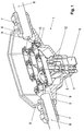
- the 1 consists essentially of a T-shaped housing 1, which has an upper crossbar 2 and a base 3.
- a plug connection 5 provided with plug contacts 4 is arranged at the base.
- This plug connection is designed as a plug connection known per se, so that commercially available plug connectors can be plugged onto it.
- PG screw connections 7 are provided on both sides 6 of the crossbar, through which the ends of a conductor strand 8 are inserted into the housing.
- the individual conductors 9 of the conductor strand or cable are connected to one another via busbars 10.
- the connections of the conductors to the busbars are preferably designed as cage tension springs 11.
- the busbars also have a molded part 12, each of which has an associated contact 4 of the plug connection and the end of which is connected to the contact.
- the wiring structure within the housing 1 is essentially T-shaped. Although a T-shaped housing is therefore preferably also provided, this is not absolutely necessary, however, the housing may also have a different geometric shape.
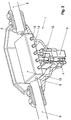
- an electronic circuit 13 is provided in the housing 1, via which the conductors 9 of the conductor strand are guided and the conductors are directly connected.
- switching means (not shown in detail here) are provided, by means of which the consumer connected to the plug connection can be switched.
- the switching means are controlled via separate control lines or via control lines which are provided in addition to the conductors 9 in the cable of the conductor strand.
- the electronic circuit can also with indicator lights 14, such as. B. LEDs, and buttons or switches 15 are provided, which are visible or accessible from the outside of the housing. The light indicators are used to indicate the operating status of the connected consumer and the buttons or switches can be used to reset or influence the logic of the electronic circuit in the event of a fault.
- the signals for controlling the Switching means on the conductor 9 of the conductor strand transmitting the electrical power are modulated. It is then in the electronic circuit logic for detection and decoding provided the control signals recognizes and causes the corresponding control of the switching means.
- control signals as optical signals via optical fibers in the housing 1 are guided.
- optical signals into electrical Signals to control the switching means is then a corresponding one Device provided in the electronic circuit 13.
- the housing 1 can also be designed to be EMC-tight on the one hand, the switching means are influenced by external interference signals avoid and on the other hand to emit interference signals when To prevent switching of the switching means out of the housing.
Abstract
Description
Die Erfindung betrifft einen Leitungsverzweiger zur Verzweigung eines Leiterstranges.
Derartige Leitungsverzweiger werden zum Anschluß elektrischer Verbraucher
in vernetzten elektrischen Anlagen verwendet, wobei ein Leiterstrang
zur Versorgung der Verbraucher mit der erforderlichen elektrischen Leistung
vorgesehen ist und die Verbraucher elektrisch gesehen, parallel an den
Leitungsstrang geschaltet sind. Die Ansteuerung der Verbraucher, d. h. die
Auswahl, welcher der Verbraucher eingeschaltet werden soll, erfolgt über
ein Signalbussystem.
Es ist bekannt, den Leiterstrang über Anschlußdosen der Verbraucher zu
führen, wobei der Leiterstrang dann praktisch durch diese Anschlußdosen
geschleift ist. Bei Ausfall eines Verbrauchers und dem erforderlichen Austausch,
müssen die Leitungen getrennt werden, wobei nachfolgende Verbraucher
dann zumindest zeitweise vom Leitungsstrang abgetrennt sind.
Dabei ist aber auch das Auswechseln eines defekten Verbrauchers bzw. der
Anschluß eines neuen Verbrauchers relativ aufwendig, und wobei auch Verdrahtungs- und Anschlußfehler leicht auftreten können.The invention relates to a line splitter for branching a conductor strand.
Line distributors of this type are used for connecting electrical consumers in networked electrical systems, a conductor line being provided to supply the consumers with the required electrical power and, viewed electrically, the consumers are connected in parallel to the line line. The control of the consumers, ie the selection of which of the consumers should be switched on, is made via a signal bus system.
It is known to guide the conductor strand over consumer junction boxes, the conductor strand then being practically looped through these junction boxes. In the event of a consumer failure and the necessary replacement, the lines must be disconnected, with subsequent consumers then being at least temporarily disconnected from the wiring harness.
However, the replacement of a defective consumer or the connection of a new consumer is also relatively complex, and wiring and connection errors can easily occur.
Der Erfindung liegt die Aufgabe zugrunde, einen Leitungsverzweiger zu schaffen, der den Anschluß neuer Verbraucher bzw. das Auswechseln eines Verbrauchers vereinfacht.The invention has for its object to a line splitter create the connection of new consumers or the replacement of one Simplified.
Diese Aufgabe wird dadurch gelöst, daß der Leitungsverzweiger ein Gehäuse aufweist, durch das der Leiterstrang unter Zwischenschaltung einer im wesentlichen T-förmige Verdrahtungsstruktur durchgeschleift ist, daß an einer Seite des Gehäuses ein Steckanschluß vorgesehen ist, und daß die Leiter des Leiterstranges über die Verdrahtungsstruktur miteinander verbunden und die Kontakte des Steckanschlusses mit den Leitern des Leiterstranges verbunden sind.This object is achieved in that the line distributor has a housing has through which the conductor strand with the interposition of an im essential T-shaped wiring structure is looped through that on a Side of the housing a plug connection is provided, and that the Conductor of the conductor strand connected to one another via the wiring structure and the contacts of the plug connection with the conductors of the conductor strand are connected.
Vorteilhafte Ausgestaltungen der Erfindung sind in den Ansprüchen 2 bis 20
angegeben.Advantageous embodiments of the invention are in
Die mit der Erfindung erzielten Vorteile bestehen insbesondere darin, daß der Leiterstrang unterbrechungslos durch den Leitungsverzweiger durchgeschleift ist und daß der Neuanschluß bzw. das Auswechseln eines Verbrauchers über einen einfachen Steckanschluß erfolgt, wobei der Leiterstrang nicht unterbrochen werden muß.The advantages achieved by the invention are in particular that the conductor strand is looped through the line distributor without interruption is and that the new connection or the replacement of a consumer via a simple plug-in connection, the conductor strand does not have to be interrupted.
Ein Ausführungsbeispiel der Erfindung ist in der Zeichnung dargestellt und wird im folgenden näher erläutert. Es zeigen
- Fig. 1
- die Ansicht eines Leitungsverzweigers, und
- Fig. 2
- eine Ansicht eines Leitungsverzweigers mit integrierter elektronischer Schaltung.
- Fig. 1
- the view of a manifold, and
- Fig. 2
- a view of a line distributor with integrated electronic circuit.
Der in der Fig. 1 dargestellte Leitungsverzweiger besteht im wesentlichen
aus einem T-förmigen Gehäuse 1, das einen oberen Querbalken 2 und eine
Basis 3 aufweist. An der Basis ist ein mit Steckkontakten 4 versehener
Steckanschluß 5 angeordnet. Dabei ist dieser Steckanschluß als an sich bekannter
Steckanschluß ausgebildet, so daß handelsübliche Steckverbinder
darauf gesteckt werden können.
An den beiden Seiten 6 des Querbalkens sind PG-Verschraubungen 7 vorgesehen,
durch die die Enden eines Leiterstranges 8 in das Gehäuse eingeführt
sind. Die einzelnen Leiter 9 des Leiterstranges bzw. Kabels sind über
Stromschienen 10 miteinander verbunden. Vorzugsweise sind die Anschlüsse
der Leiter an die Stromschienen als Käfigzugfedern 11 ausgebildet. Die
Stromschienen weisen darüber hinaus noch eine Anformung 12 auf, die jeweils
zu einem zugeordneten Kontakt 4 des Steckanschlusses weist und deren
Ende mit dem Kontakt verbunden ist.
Die Verdrahtungsstruktur innerhalb des Gehäuses 1 ist im wesentlichen T-förmig
gestaltet. Wenngleich vorzugsweise daher auch ein T-förmiges Gehäuse
vorgesehen ist, ist dieses jedoch nicht zwingend notwendig, das Gehäuse
kann ggf. auch eine andere geometrische Form aufweisen.1 consists essentially of a T-
The wiring structure within the
Ggf. kann vorgesehen sein, daß auch an den Seiten 6 des Gehäuses 1
mehrpolige Steckvorrichtungen angebracht sind und daß der Leiterstrang
mittels Steckern daran angeschlossen ist. Die zum Inneren des Gehäuses 1
weisenden Enden der Kontaktelemente der Steckvorrichtungen sind dabei
dann über die Stromschienen 10 miteinander verbunden.Possibly. can be provided that also on the
In der Fig. 2 ist eine weitere Ausgestaltung des Leitungsverzweigers dargestellt.
Dabei ist in dem Gehäuse 1 eine elektronische Schaltung 13 vorgesehen,
über die die Leiter 9 des Leiterstranges geführt sind und wobei die
Leiter direkt durchverbunden sind. Zwischen den Anschlüssen der Kontaktelemente
4 des Steckanschlusses 5 sind hier nicht näher dargestellte
Schaltmittel vorgesehen, mittels denen der an den Steckanschluß angeschlossene
Verbraucher geschaltet werden kann. Die Ansteuerung der
Schaltmittel erfolgt über separate Steuerleitungen oder über Steuerleitungen,
die neben den Leitern 9 in dem Kabel des Leiterstranges vorgesehen
sind.
Die elektronische Schaltung kann dabei auch noch mit Leuchtanzeigen 14,
wie z. B. Leuchtdioden, sowie Tastern bzw. Schaltern 15 versehen sein, die
von der Außenseite des Gehäuses sichtbar bzw. zugänglich sind. Die
Leuchtanzeigen dienen dabei zur Betriebs- bzw. Statusanzeige des angeschlossenen
Verbrauchers und mit den Tastern bzw. Schaltern kann die
Logik der elektronischen Schaltung im Störungsfalle zurückgesetzt bzw. beeinflußt
werden.2 shows a further embodiment of the line splitter. In this case, an
The electronic circuit can also with indicator lights 14, such as. B. LEDs, and buttons or
Es kann auch vorgesehen sein, daß die Signale zur Ansteuerung der
Schaltmittel auf die die elektrische Leistung übertragenden Leiter 9 des Leiterstranges
aufmoduliert sind. Dabei ist dann in der elektronischen Schaltung
eine Logik zur Erkennung und Dekodierung vorgesehen, die die Steuersignale
erkennt und die entsprechende Ansteuerung der Schaltmittel bewirkt.It can also be provided that the signals for controlling the
Switching means on the
Um eine Beeinflussung der Steuersignale durch den Leitern 9 des Leiterstranges
überlagerte Störsignale zu vermeiden kann auch vorgesehen
sein, daß die Steuersignale als optische Signale über Lichtwellenleiter in
das Gehäuse 1 geführt sind. Zur Umsetzung der optischen Signale in elektrische
Signale zur Ansteuerung der Schaltmittel ist dann eine entsprechende
Einrichtung in der elektronischen Schaltung 13 vorgesehen.In order to influence the control signals by the
Schließlich kann das Gehäuse 1 auch noch EMV-dicht ausgeführt sein, um
zum einen eine Beeinflussung der Schaltmittel durch äußere Störsignale zu
vermeiden und zum anderen um ein Abstrahlen von Störsignalen beim
Schalten der Schaltmittel aus dem Gehäuse heraus zu verhindern.Finally, the
Claims (20)
Applications Claiming Priority (2)
| Application Number | Priority Date | Filing Date | Title |
|---|---|---|---|
| DE19630202A DE19630202C2 (en) | 1996-07-26 | 1996-07-26 | Line distributors |
| DE19630202 | 1996-07-26 |
Publications (3)
| Publication Number | Publication Date |
|---|---|
| EP0821458A2 true EP0821458A2 (en) | 1998-01-28 |
| EP0821458A3 EP0821458A3 (en) | 1999-03-17 |
| EP0821458B1 EP0821458B1 (en) | 2004-04-07 |
Family
ID=7800929
Family Applications (1)
| Application Number | Title | Priority Date | Filing Date |
|---|---|---|---|
| EP97112114A Revoked EP0821458B1 (en) | 1996-07-26 | 1997-07-16 | Branching device for lines |
Country Status (3)
| Country | Link |
|---|---|
| US (1) | US5937119A (en) |
| EP (1) | EP0821458B1 (en) |
| DE (2) | DE19630202C2 (en) |
Cited By (2)
| Publication number | Priority date | Publication date | Assignee | Title |
|---|---|---|---|---|
| WO2009082600A1 (en) * | 2007-12-20 | 2009-07-02 | 3M Innovative Properties Company | Electrical connector |
| US7670197B2 (en) | 2007-12-20 | 2010-03-02 | 3M Innovative Properties Company | Electrical splice connector |
Families Citing this family (5)
| Publication number | Priority date | Publication date | Assignee | Title |
|---|---|---|---|---|
| DE19906465C2 (en) * | 1999-02-16 | 2001-02-15 | Krone Gmbh | Power distribution box |
| FR2815179B1 (en) * | 2000-10-10 | 2002-12-20 | Schneider Electric Ind Sa | CONNECTOR WITH REMOVABLE PLUGS FOR ELECTRICAL PIPING |
| FR2815180B1 (en) * | 2000-10-10 | 2002-12-20 | Schneider Electric Ind Sa | CONNECTOR WITH REMOVABLE PLUGS FOR ELECTRICAL PIPING |
| DE202004014562U1 (en) * | 2004-09-16 | 2004-11-18 | Schmitt, Fred R. | Housing for connectors |
| TWI740050B (en) | 2018-06-01 | 2021-09-21 | 日商島野股份有限公司 | Electric cable assembly for human-powered vehicle |
Citations (9)
| Publication number | Priority date | Publication date | Assignee | Title |
|---|---|---|---|---|
| US4392701A (en) * | 1980-07-16 | 1983-07-12 | Amp Incorporated | Tap connector assembly |
| US4405187A (en) * | 1980-06-06 | 1983-09-20 | Krone Gmbh | Connector assembly for PCM cables |
| DE3412116A1 (en) * | 1984-03-31 | 1985-10-10 | U.I. Lapp Kg, 7000 Stuttgart | Device for reequipping cable, line and hose screw unions with bending protection |
| US4571018A (en) * | 1984-05-15 | 1986-02-18 | Houston Geophysical Products, Inc. | Seismic marsh T-coupler with removable polarized connectors |
| US4767168A (en) * | 1986-12-24 | 1988-08-30 | Prestolite Wire Corporation | Hybrid connector cable system |
| US4857016A (en) * | 1983-03-30 | 1989-08-15 | Butler Manufacturing Company | Components for flexible wiring systems |
| US5293298A (en) * | 1991-10-16 | 1994-03-08 | International Business Machines Corporation | Electrical connector |
| DE19517153A1 (en) * | 1994-05-10 | 1995-11-16 | Miguel Francisco Jo Traspuesto | Electric device multiple current connector plug |
| DE29501970U1 (en) * | 1995-02-07 | 1996-06-05 | Lumberg Karl Gmbh & Co | Connection device for the optional production of a reusable electrical connection or tap on multi-core electrical lines |
Family Cites Families (5)
| Publication number | Priority date | Publication date | Assignee | Title |
|---|---|---|---|---|
| FR2356171A1 (en) * | 1976-01-27 | 1978-01-20 | Thomson Csf | OPTO-ELECTRIC BYPASS FOR OPTICAL FIBER BEAM LINKS |
| US4234760A (en) * | 1978-12-18 | 1980-11-18 | Amp Incorporated | Covering for T-tap terminals |
| DE9217344U1 (en) * | 1992-12-18 | 1993-02-18 | Mannesmann Kienzle Gmbh, 7730 Villingen-Schwenningen, De | |
| US5757994A (en) * | 1995-09-22 | 1998-05-26 | Boeing North American, Inc. | Three-part optical coupler |
| US5666448A (en) * | 1995-09-22 | 1997-09-09 | Rockwell International Corporation | Variable splitting optical coupler |
-
1996
- 1996-07-26 DE DE19630202A patent/DE19630202C2/en not_active Expired - Fee Related
-
1997
- 1997-07-09 US US08/890,475 patent/US5937119A/en not_active Expired - Fee Related
- 1997-07-16 DE DE59711489T patent/DE59711489D1/en not_active Revoked
- 1997-07-16 EP EP97112114A patent/EP0821458B1/en not_active Revoked
Patent Citations (9)
| Publication number | Priority date | Publication date | Assignee | Title |
|---|---|---|---|---|
| US4405187A (en) * | 1980-06-06 | 1983-09-20 | Krone Gmbh | Connector assembly for PCM cables |
| US4392701A (en) * | 1980-07-16 | 1983-07-12 | Amp Incorporated | Tap connector assembly |
| US4857016A (en) * | 1983-03-30 | 1989-08-15 | Butler Manufacturing Company | Components for flexible wiring systems |
| DE3412116A1 (en) * | 1984-03-31 | 1985-10-10 | U.I. Lapp Kg, 7000 Stuttgart | Device for reequipping cable, line and hose screw unions with bending protection |
| US4571018A (en) * | 1984-05-15 | 1986-02-18 | Houston Geophysical Products, Inc. | Seismic marsh T-coupler with removable polarized connectors |
| US4767168A (en) * | 1986-12-24 | 1988-08-30 | Prestolite Wire Corporation | Hybrid connector cable system |
| US5293298A (en) * | 1991-10-16 | 1994-03-08 | International Business Machines Corporation | Electrical connector |
| DE19517153A1 (en) * | 1994-05-10 | 1995-11-16 | Miguel Francisco Jo Traspuesto | Electric device multiple current connector plug |
| DE29501970U1 (en) * | 1995-02-07 | 1996-06-05 | Lumberg Karl Gmbh & Co | Connection device for the optional production of a reusable electrical connection or tap on multi-core electrical lines |
Cited By (2)
| Publication number | Priority date | Publication date | Assignee | Title |
|---|---|---|---|---|
| WO2009082600A1 (en) * | 2007-12-20 | 2009-07-02 | 3M Innovative Properties Company | Electrical connector |
| US7670197B2 (en) | 2007-12-20 | 2010-03-02 | 3M Innovative Properties Company | Electrical splice connector |
Also Published As
| Publication number | Publication date |
|---|---|
| DE19630202A1 (en) | 1998-01-29 |
| EP0821458A3 (en) | 1999-03-17 |
| US5937119A (en) | 1999-08-10 |
| EP0821458B1 (en) | 2004-04-07 |
| DE59711489D1 (en) | 2004-05-13 |
| DE19630202C2 (en) | 1999-09-23 |
Similar Documents
| Publication | Publication Date | Title |
|---|---|---|
| DE112011101265B4 (en) | backup unit | |
| DE102008058090B4 (en) | Input / output module for an automation device | |
| DE102017219214B4 (en) | BRANCH STRUCTURE AND WIRING HARNESS | |
| EP2710619B1 (en) | System cabling for a multiple relay arrangement | |
| DE102008050322B4 (en) | Electric motor connection and electric motor | |
| EP3073176B1 (en) | Electrical connection assembly for lights | |
| EP0821458B1 (en) | Branching device for lines | |
| EP3631922B1 (en) | Current distributor | |
| EP2105033B1 (en) | Distributor device for use in communication and data systems technology | |
| DE69819983T2 (en) | Power distribution system | |
| EP0759651A2 (en) | Contact module for insertion in flush-mounted boxes | |
| DE19743972A1 (en) | Electronic input / output module | |
| DE3537432C2 (en) | ||
| EP0984169B1 (en) | Valve arrangement with at least one valve unit consisting of several electrically-actuated valves | |
| DE102008020348A1 (en) | Current distribution board for use in supply module for aircraft, has current distributor exhibiting staybolt for connection of electrical supply line, where staybolt and sockets are electrically and conductively connected with each other | |
| EP0536442B1 (en) | Terminal block for side by side mounting | |
| EP1169762B1 (en) | Bus system with a data bus line and a power bus line | |
| DE102007046433A1 (en) | distribution facility | |
| DE102004036163A1 (en) | Controller for electrohydraulic expansion controllers has connection strip with additional holder in which connecting plug is fixed to which lamp connecting plug can be connected to connect lamp to intrinsically safe external power supply | |
| AT503637B1 (en) | CABLE WITH CONNECTOR, CONNECTOR FOR A CABLE AND METHOD FOR CONNECTING A CABLE WITH A CONNECTOR | |
| DE3302373A1 (en) | Switching installation terminal block | |
| DE10041438B4 (en) | Arrangement for coupling a plurality of first optical waveguide fibers with a plurality of second optical waveguide fibers | |
| DE10261927B4 (en) | Flat Cable System | |
| DE102019006330A1 (en) | Electrical terminal block | |
| DE10357468A1 (en) | Conductor line for ordering or appliance conncting in communication installation applicable to networks with high transmission rates with insulated and possibly screened multicore cable and plug contacts at each line end |
Legal Events
| Date | Code | Title | Description |
|---|---|---|---|
| PUAI | Public reference made under article 153(3) epc to a published international application that has entered the european phase |
Free format text: ORIGINAL CODE: 0009012 |
|
| AK | Designated contracting states |
Kind code of ref document: A2 Designated state(s): DE FR GB IT |
|
| AX | Request for extension of the european patent |
Free format text: AL;LT;LV;RO;SI |
|
| PUAL | Search report despatched |
Free format text: ORIGINAL CODE: 0009013 |
|
| AK | Designated contracting states |
Kind code of ref document: A3 Designated state(s): AT BE CH DE DK ES FI FR GB GR IE IT LI LU MC NL PT SE |
|
| AX | Request for extension of the european patent |
Free format text: AL;LT;LV;RO;SI |
|
| 17P | Request for examination filed |
Effective date: 19990517 |
|
| AKX | Designation fees paid |
Free format text: DE FR GB IT |
|
| 17Q | First examination report despatched |
Effective date: 20021125 |
|
| GRAP | Despatch of communication of intention to grant a patent |
Free format text: ORIGINAL CODE: EPIDOSNIGR1 |
|
| RAP1 | Party data changed (applicant data changed or rights of an application transferred) |
Owner name: HARTING ELECTRIC GMBH & CO. KG |
|
| GRAS | Grant fee paid |
Free format text: ORIGINAL CODE: EPIDOSNIGR3 |
|
| GRAA | (expected) grant |
Free format text: ORIGINAL CODE: 0009210 |
|
| AK | Designated contracting states |
Kind code of ref document: B1 Designated state(s): DE FR GB IT |
|
| REG | Reference to a national code |
Ref country code: GB Ref legal event code: FG4D Free format text: NOT ENGLISH |
|
| REF | Corresponds to: |
Ref document number: 59711489 Country of ref document: DE Date of ref document: 20040513 Kind code of ref document: P |
|
| GBT | Gb: translation of ep patent filed (gb section 77(6)(a)/1977) |
Effective date: 20040615 |
|
| ET | Fr: translation filed | ||
| PLBQ | Unpublished change to opponent data |
Free format text: ORIGINAL CODE: EPIDOS OPPO |
|
| PLBI | Opposition filed |
Free format text: ORIGINAL CODE: 0009260 |
|
| PLAX | Notice of opposition and request to file observation + time limit sent |
Free format text: ORIGINAL CODE: EPIDOSNOBS2 |
|
| 26 | Opposition filed |
Opponent name: PHOENIX CONTACT GMBH & CO. KG Effective date: 20050107 |
|
| PLAX | Notice of opposition and request to file observation + time limit sent |
Free format text: ORIGINAL CODE: EPIDOSNOBS2 |
|
| PLBB | Reply of patent proprietor to notice(s) of opposition received |
Free format text: ORIGINAL CODE: EPIDOSNOBS3 |
|
| PLAY | Examination report in opposition despatched + time limit |
Free format text: ORIGINAL CODE: EPIDOSNORE2 |
|
| PLAH | Information related to despatch of examination report in opposition + time limit modified |
Free format text: ORIGINAL CODE: EPIDOSCORE2 |
|
| PLBC | Reply to examination report in opposition received |
Free format text: ORIGINAL CODE: EPIDOSNORE3 |
|
| PGFP | Annual fee paid to national office [announced via postgrant information from national office to epo] |
Ref country code: DE Payment date: 20070713 Year of fee payment: 11 |
|
| PGFP | Annual fee paid to national office [announced via postgrant information from national office to epo] |
Ref country code: GB Payment date: 20070625 Year of fee payment: 11 |
|
| PGFP | Annual fee paid to national office [announced via postgrant information from national office to epo] |
Ref country code: IT Payment date: 20070721 Year of fee payment: 11 |
|
| RDAF | Communication despatched that patent is revoked |
Free format text: ORIGINAL CODE: EPIDOSNREV1 |
|
| PGFP | Annual fee paid to national office [announced via postgrant information from national office to epo] |
Ref country code: FR Payment date: 20070718 Year of fee payment: 11 |
|
| RDAG | Patent revoked |
Free format text: ORIGINAL CODE: 0009271 |
|
| STAA | Information on the status of an ep patent application or granted ep patent |
Free format text: STATUS: PATENT REVOKED |
|
| 27W | Patent revoked |
Effective date: 20071210 |
|
| GBPR | Gb: patent revoked under art. 102 of the ep convention designating the uk as contracting state |
Effective date: 20071210 |
|
| PLAB | Opposition data, opponent's data or that of the opponent's representative modified |
Free format text: ORIGINAL CODE: 0009299OPPO |