EP0776485B1 - Apparatus and method for determining the position of a work implement - Google Patents
Apparatus and method for determining the position of a work implement Download PDFInfo
- Publication number
- EP0776485B1 EP0776485B1 EP96914758A EP96914758A EP0776485B1 EP 0776485 B1 EP0776485 B1 EP 0776485B1 EP 96914758 A EP96914758 A EP 96914758A EP 96914758 A EP96914758 A EP 96914758A EP 0776485 B1 EP0776485 B1 EP 0776485B1
- Authority
- EP
- European Patent Office
- Prior art keywords
- coordinate system
- receiving means
- site
- receiving
- current
- Prior art date
- Legal status (The legal status is an assumption and is not a legal conclusion. Google has not performed a legal analysis and makes no representation as to the accuracy of the status listed.)
- Expired - Lifetime
Links
Images


Classifications
-
- G—PHYSICS
- G01—MEASURING; TESTING
- G01S—RADIO DIRECTION-FINDING; RADIO NAVIGATION; DETERMINING DISTANCE OR VELOCITY BY USE OF RADIO WAVES; LOCATING OR PRESENCE-DETECTING BY USE OF THE REFLECTION OR RERADIATION OF RADIO WAVES; ANALOGOUS ARRANGEMENTS USING OTHER WAVES
- G01S19/00—Satellite radio beacon positioning systems; Determining position, velocity or attitude using signals transmitted by such systems
- G01S19/38—Determining a navigation solution using signals transmitted by a satellite radio beacon positioning system
- G01S19/39—Determining a navigation solution using signals transmitted by a satellite radio beacon positioning system the satellite radio beacon positioning system transmitting time-stamped messages, e.g. GPS [Global Positioning System], GLONASS [Global Orbiting Navigation Satellite System] or GALILEO
- G01S19/42—Determining position
- G01S19/45—Determining position by combining measurements of signals from the satellite radio beacon positioning system with a supplementary measurement
-
- E—FIXED CONSTRUCTIONS
- E02—HYDRAULIC ENGINEERING; FOUNDATIONS; SOIL SHIFTING
- E02F—DREDGING; SOIL-SHIFTING
- E02F3/00—Dredgers; Soil-shifting machines
- E02F3/04—Dredgers; Soil-shifting machines mechanically-driven
- E02F3/76—Graders, bulldozers, or the like with scraper plates or ploughshare-like elements; Levelling scarifying devices
- E02F3/80—Component parts
- E02F3/84—Drives or control devices therefor, e.g. hydraulic drive systems
- E02F3/844—Drives or control devices therefor, e.g. hydraulic drive systems for positioning the blade, e.g. hydraulically
- E02F3/847—Drives or control devices therefor, e.g. hydraulic drive systems for positioning the blade, e.g. hydraulically using electromagnetic, optical or acoustic beams to determine the blade position, e.g. laser beams
-
- G—PHYSICS
- G01—MEASURING; TESTING
- G01S—RADIO DIRECTION-FINDING; RADIO NAVIGATION; DETERMINING DISTANCE OR VELOCITY BY USE OF RADIO WAVES; LOCATING OR PRESENCE-DETECTING BY USE OF THE REFLECTION OR RERADIATION OF RADIO WAVES; ANALOGOUS ARRANGEMENTS USING OTHER WAVES
- G01S19/00—Satellite radio beacon positioning systems; Determining position, velocity or attitude using signals transmitted by such systems
- G01S19/38—Determining a navigation solution using signals transmitted by a satellite radio beacon positioning system
- G01S19/39—Determining a navigation solution using signals transmitted by a satellite radio beacon positioning system the satellite radio beacon positioning system transmitting time-stamped messages, e.g. GPS [Global Positioning System], GLONASS [Global Orbiting Navigation Satellite System] or GALILEO
- G01S19/42—Determining position
- G01S19/43—Determining position using carrier phase measurements, e.g. kinematic positioning; using long or short baseline interferometry
- G01S19/44—Carrier phase ambiguity resolution; Floating ambiguity; LAMBDA [Least-squares AMBiguity Decorrelation Adjustment] method
-
- G—PHYSICS
- G01—MEASURING; TESTING
- G01S—RADIO DIRECTION-FINDING; RADIO NAVIGATION; DETERMINING DISTANCE OR VELOCITY BY USE OF RADIO WAVES; LOCATING OR PRESENCE-DETECTING BY USE OF THE REFLECTION OR RERADIATION OF RADIO WAVES; ANALOGOUS ARRANGEMENTS USING OTHER WAVES
- G01S19/00—Satellite radio beacon positioning systems; Determining position, velocity or attitude using signals transmitted by such systems
- G01S19/38—Determining a navigation solution using signals transmitted by a satellite radio beacon positioning system
- G01S19/39—Determining a navigation solution using signals transmitted by a satellite radio beacon positioning system the satellite radio beacon positioning system transmitting time-stamped messages, e.g. GPS [Global Positioning System], GLONASS [Global Orbiting Navigation Satellite System] or GALILEO
- G01S19/53—Determining attitude
Definitions
- This invention relates to an apparatus and method for determining the position of a work implement in a site coordinate system and more particularly to a method and apparatus for determining the position of first and second end points in a local coordinate system relative to a supporting frame and transforming the position of the first and second points to a site coordinate system.
- Machines for example, motor graders, dozers, compactors, pavers, and profilers to name a just a few, are used for geographic surface altering operations. Such machines typically operate at construction sites which were previously manually surveyed, and staked according to construction site plans. During the process the construction site is frequently checked in order to confirm that the processed site meets the design specifications. This process requires large amounts of manual labor much of which is by highly trained personnel. Further, the machine operator must be highly trained in order to obtain the degree of accuracy required.
- Laser systems have been in used in some applications to provide a reference for the operator to follow.
- a laser beam emitted by a laser positioned at a surveyed location on the site is swept over the site. This establishes a laser plane.
- a receiver on the machine receives the laser beam and indicates to the operator the elevational position of the beam relative to a location on the machine, such as the machine or implement. This information is used by the machine operator for machine controlling purposes.
- An example of one such system is shown in United States Patent 4,807,131 dated 21 February 1989, to Philip M. Clegg.
- This patent discloses measuring the elevational position of the grading blade relative to the laser plane and displaying on a monitor parameters such as target elevation, actual elevation, and an allowable range of error so that the operator can, in one mode of operation, adjust the blade position to be within tolerance of the target location.
- Implements are normally adjustably connected to the machine frame so that the slope, pitch, and elevation of the work implement can be varied relative to the machine.
- the laser receiver When the laser receiver is mounted on the machine frame any change in the position of the work implement relative to the frame causes an unaccounted for change in the position of the work implement relative to the plane and the receiver. The information therefore provided to the operator is less than desirable and may not be used to any significant advantage.
- Placing a single laser receiver on the work implement eliminates this problem to the extent that the laser receiver moves with the work implement and is related to work implement position. However, any changes in tilt, pitch or rotation of the work implement relative to the laser plane are not compensated for and therefore the information provided is still not accurate.
- Placing two laser receivers on the implement permits the slope of the blade to be determined relative to the laser plane however this does not allow for the change in position of the implement caused by implement tipping (pitching).
- Any GPS receiver mounted on a work implement must be spaced from the cutting edge because of the harsh environment in which the implement operates. Since the GPS receiver determines the position of the antenna of the receiver in space and not the position of the cutting edge, any variations in the orientation of the work implement, such as described above, reduces the possibility of being able to accurately determine the cutting edge position. For at least the above reasons placement of a GPS receiver on the work implement would not be considered.
- the accuracy of determining the coordinate position of a work implement relative to a work site using a GPS receiver is less than required to meet acceptable standards.
- the measurement accuracy in the elevational direction of the site coordinate system is particularly important in applications where the end product is a finished surface, for example, a road way surface. Attempts to address this problem are being made but have not resulted in an accurate enough GPS.
- the present invention is directed to overcoming one or more of the problems as set forth above.
- FR-A-2637625 discloses an object position and orientation determining system and method which uses a three-dimensional coordinate system within which the position of a working tool (2) is defined in terms of three primary 'theoretical' parameters (XA,YA,ZA). These parameters define a virtual surface plane (A-B) corresponding to the required finished surface. A series of second 'real' parameters are defined within the same coordinate system to indicate the actual position of the tool at any given moment. The control system compares these to the theoretical parameters and issues control commands for displacement of the tool to correct any difference between the two sets of parameters.
- An apparatus for determining the position of a work implement movably connected to a geographical surface altering machine comprising:
- the apparatus may also include means for sensing a change in the pitch angle of the work implement and determining a related current position of the first and second point locations on the work implement in the local coordinate system.
- the processing means converts the current position of the first and second points in the site coordinate system.
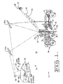
- an apparatus 10 for determining the position of a work implement 12 of a geographic surface altering machine 16 is shown.
- the work implement 12 shown as an earth working blade, is controllably movably mounted on a frame 14 of a geographic surface altering machine 16, shown as a motorgrader.
- a geographic surface altering machine 16 shown as a motorgrader.
- other machines such as dozers, scrapers, compactors, pavers, profilers and the like, equipped with suitable surfacing altering implements, are equivalents and considered within the scope of the invention.
- the apparatus 10 optionally includes a laser scanner 22.
- the laser scanner 22 is adapted to deliver a low intensity laser beam 26 swept about a substantially vertical axis 28.
- the laser scanner 22 is positioned at a preselected coordinate location ("x", "y") within a surveyed area hereinafter referred to as a work site 32.
- the swept laser beam 26 defines a plane 30 at a predetermined elevational position along the vertical axis 28 and establishes an accurate elevational coordinate position "z".
- the apparatus 10 includes a global positioning system (GPS) 24.
- GPS global positioning system
- the GPS 24 includes a constellation of satellites, two of which are shown at 34a and 34b.
- the global positioning system 24 includes a base station 36 and a reference receiving means 38 connected to the base station 36.
- the reference receiving means 38 is adapted to receive electromagnetic radiation delivered from a plurality of locations and responsively produce reference positioning signals.
- the reference receiving means 38 includes a GPS reference receiver 39.
- the base station 36 is located at a known, fixed position, at the work site 32.
- a transceiver 40 at the base station 36 and a transceiver 42 on the machine 16 provides an RF communication link between the machine 16 and the base station 36 over which reference position data is transferred.
- a base station processor (not shown) is used in determining the position of the base station relative to the center of the earth.
- the global positioning system 24 further includes a first receiving means 18 for receiving electromagnetic radiation delivered from a plurality of remote locations and responsively producing a first position signal and a second receiving means 20 for receiving electromagnetic radiation delivered from said plurality of remote locations and responsively producing a second position signal.
- the first receiving means 18 is connected at a first preselected location on the work implement 12 and the second receiving means 20 is connected at a second preselected location on the work implement 12.
- the first receiving means 18 includes a first GPS receiver 44 and the second receiving means 20 includes a second GPS receiver 46.
- the first and second GPS receivers each have an antenna 48,50 and a pre-amplifier (not shown). Position signals received by the first and second antennas 48,50 are amplified and delivered to the first and second receivers 44,46.
- the first and second receivers 44,46 decode the navigation signals and produce a pseudorange and a satellite position for each selected satellite.
- a processing means 51 including a position computer 52, calculates the position of the first and second receivers based on the pseudorange and satellite positions.
- the first and second receivers 44,46 determine the position of a receiving point location "R", "L” on the first and second antennas 48,50, respectively.
- the receiving points "R", “L” are the effective center of receipt of the GPS signals and are used in subsequent calculations. Global position systems such as this are known to those skilled in the art and will therefore not be discussed in any greater detail.
- the implement 12 as shown in Fig. 3, includes an earth grading blade 70, having first and second sides 58,60, a cutting edge 66 and an upper edge 68.
- an earth grading blade 70 having first and second sides 58,60, a cutting edge 66 and an upper edge 68.
- the first antenna 48 is mounted on the blade 70 adjacent the first side 58 and the second antenna 50 is mounted on the blade 70 adjacent the second side 60.
- the receiving points "R", “L” are spaced a preselected distance “W” apart. As shown, the particular distance “W” is substantially equal in magnitude to a distance between the first and second blade sides 58,60.
- the first and second receiving points "R”, “L” are positioned with respect to first and second point locations "RB", "LB” which preferably lie along the cutting edge 66 of the blade 70.
- the first and second point locations "RB”, “LB” are preferably at first and second corners of the blade 70, at the intersection of the first and second sides and the cutting edge 66, and a distance "B" apart.
- the distance “B” is preferably equal to distance "A”. Placing the first and second antennas 48,50 (receiving points “R”, “L”) and the first and second points “RB”, “LB” at these locations simplifies three dimensional space transformation calculations between the first and second receiving points "R", “L” and the first and second point locations "RB", "LB” of the blade 70.
- the first and second receiving means 18,20 are located along first and second axial lines 73,75 extending perpendicular to the cutting edge 66 and parallel to each other. It should be recognized however that other locations may be selected.
- the first and second receiving means 18,20 optionally include first and second laser receivers 72,74 connected to the blade at the aforementioned first and second predetermined spaced apart locations.
- the first and second laser receivers are at the location of the first and second antennas 48,50, respectively.
- the first and second antennas 48,50 are mounted on one end portion of the first and second laser receivers 72,74, respectively, and the other end portion of the laser receivers 72,74 are connected to the blade 70 at the upper edge 68.
- the laser receivers 72,74 are incremental lazer receivers and include a plurality of linearly aligned photo receptors 76 and associated circuitry (not shown) for delivering an output signal representative of the particular receptor illuminated.
- the construction of laser receivers of this type are well known in the art and will therefore not be discussed in any greater detail.
- the first and second laser receivers 72,74 are provided to improve the accuracy of the implement 12 position measurement in the elevational direction and to supplement the measurement obtained from the global positioning system.
- the first and second laser receivers 72,74 are connected to the position computer 52.
- the laser receivers deliver output signals to the position computer 52 and the position computer determines the elevational coordinate position "z" of the blade 70 in three dimensional space relative to the particular work site.
- the first and second lines 73,75 extend along the length of the first and second laser receivers and pass through the receiving points "R" and "L".
- the reference receiver 39 located at the base station 36, receives signals from the constellation of GPS satellites.
- the base station computer (not shown) which is connected to the receiver 39 determines the position of the receiver 39 (antenna 78) with respect to the center of the Earth.
- the reference receiver 39 is used to make a "differential global positioning system".
- the first and second receivers 44,46 and the reference receiver 39 are commercially available and includes the antenna, preamplifier and receiver.
- the position and base station computers 52 include a commercially available microprocessor from Motorola, Inc., of Schaumburg, Illinois, U.S.A.
- the blade 70 is movably connected to the frame 14 by a supporting mechanism 80.
- the supporting mechanism 80 includes a circle drive mechanism 82 having a selectively actuatable rotary drive motor 84 for rotating a circle 85 and the blade 70 connected thereto about an elevational axis located at the center of the circle 85 in a known manner.
- a pair of selectively actuatable fluid operated lift jacks 86,88 are connected to and between the frame 14 and the supporting mechanism 80.
- the lift jacks 86,88 elevationally move the blade 70 relative to the frame 14. Simultaneous extension of the lift jacks 86,88 lowers the blade 70 and simultaneous retraction of lift jacks 86,88 raises the blade 70. Extension or retraction of either one of the lift jacks 86,88, or extension of one and retraction of the other of the lift jacks 86,88 results in tilting of the blade 70 relative to the frame 14 in directions transverse the direction of movement of the machine 16.
- a fluid operated tip jack 90 is connected to and between the supporting mechanism 80 and a bellcrank 92.
- the bellcrank 92 pivotally connects the blade 70 to the circle drive mechanism 82.
- the tip jack 90 is extensibly movable for tipping the bellcrank 92 about the pivotal connection. This results in tipping movement of the blade 70 in forward or rearward directions, as shown in phantom lines in Fig. 4, with the blade oriented transversely of the vehicle frame 14. It should be noted that the terms tip and pitch are used interchangeably and have the same meaning.
- a sensing means 94 is provided for sensing a change in the pitch angle ⁇ of the blade 70 and delivering a responsive pitch angle signal.
- the sensing means 94 includes any appropriate transducer 96 capable of sensing the tipped position of the blade about the bellcrank pivot axis.
- a potentiometer, an encoder, a resolver, and the like The transducer 96 is connected to the bellcrank and delivers the pitch angle signal to the position computer 52.
- the pitch angle signal may be either analog or digital. Should an analog signal be delivered an A/D converter is required to convert the signal for digital processing by the processing means 51.
- the position computer 52 determines a related current position of the first and second point locations , on the work implement in a local coordinate system.
- the local coordinate system is a three dimensional coordinate system established relative to the frame 14 (supporting structure 80). As seen in Fig. 5, blade 70 is shown as being viewed from the second side 60 and looking down along the blade 70.
- the processing means 51 receives the first and second position signals from the first and second receiving means 18,20 and determines first and second current coordinate positions "L","R", of the first and second receiving means 18,20, on a realtime basis, in a site coordinate system related to the work site 32 above. It is to be noted that the first and second signals may include the laser position signals as indicated above when additional accuracy in the elevational direction is required. The processing means 51 preferably disregards the GPS elevational component "z" when a laser position signal is provided.
- the processing means 51 determines a plane 98 in space passing through the first and second current coordinate positions "L", “R” and a mid-point position "C", lying along a substantially straight line 99 passing between first and second previously defined coordinate positions "L'", “R'” of the first and second receiving means 18,20 in the site coordinate system.
- the most recent previously determined coordinate positions "L'", “R”' are stored in a memory (not shown) of the processing means 51.
- the plane 98 is defined by a first vector RL extending from the first current coordinate position "R” to the second current coordinate position "L", and a second vector RC extending from the first current coordinate position "R” and the midpoint "C" in the site coordinate system.
- RL (L x - R x )i + (L y - R y )j + (L z - R z )k
- RC (C x - R x )i + (C y - R y )j + (C y - R y )k
- the current positions of the first and second points and in the local coordinate system are determined during initialization of the apparatus, for example such as by switching the apparatus 10 to an "on" position to activate the receiving means 18,20, the processing means 51 and the pitch angle sensor 94. Subsequent determination of the positions of the first and second points and in the local coordinate system are updated when there is a change in the tip angle ⁇ as sensed by the sensing means 94. This is achieved by the processing means 51 comparing the current pitch angle to a previously sensed pitch angle ⁇ ' and determining the current previous sensed stored position of the first and second points and , stored in the memory thereof (not shown), and updating the information to the current position of the first and second points and in the local coordinate system.
- the vectors at RB and LB contain the coordinates of the first and second point locations RB and LB on the blade 70.
- the processing means 51 includes a database computer 100, of any suitable type, for example an IBM personal computer having an Intel 486 microprocessor, and adequate memory is connected to the position computer 52.
- the database computer 100 receives signals from the position computer 52 and updates in real time the current coordinate position of the first and second point locations RB, LB on the blade 70 within the work site as the machine 16 traverses the work site.
- the database computer 100 is also connected to a transceiver 103.
- the transceiver 103 is mounted on the machine 16 and in radio frequency transmission communication with the transceiver 40 at the base station 36.
- the transceiver 40 is connected to a landbase computer (not shown) located at the base station 36.
- the transceiver 40 communicates with the transceiver 103 and transfers data between the database computer 100 and the landbase computer. Data such as machine position, implement position, changes to the earth's topography and the like are transmitted therebetween. For example, changes made to the earth by the implement 12 during operation of the machine 16 are updated in real time in the position computer 52 located on the machine 16, based on the tracking of the first and second points RB, LB in the site coordinate system. Information such as this is transmitted to update the landbase computer to update the site map retained therein.
- the database computer 100 delivers signals to the monitor 102 which displays pictorially or graphically the current position of the blade relative to the work site.
- the display is preferably a two dimension elevational crossection of the work site showing the blade in transverse elevation as seen in Fig. 4.
- a three dimensional representation of the blade 70 in three dimensional space is within the scope of the invention.
- Digitized plans or models of the actual work site may be loaded into the database computer 100.
- a digitized plan or model of the desired work site may also be loaded into the database computer 100.
- the actual work site data is updated in real time based on the position of the first and second point locations RB, LB, as determined above.
- the database being dynamic facilitates realtime tracking of the first and second point locations RB, LB and the area of the earth's surface being altered by the blade 70 as the blade traverses the work site.
- a responsive signal is delivered from the database computer 100 to the monitor 102 and the current position of the blade 70, the actual work site, as altered, and the desired work site elevation is displayed on the monitor 102.
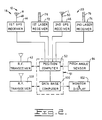
- a flow chart depicting a method for determining the position of the work implement 12 in the site coordinate system is shown in substantial detail.
- the method utilizes the analysis as set forth in the above description and applies it in a logical sequence for purposes of monitoring and when appropriate for controlling the implement 12.
- the steps shown in boxes 104-120 are performed by the processing means 51 with the results being displayed as discussed above on the monitor 102 as long as the system is activated, the control switch (not shown) in the "on" position.
- the step of determining the current pitch angle ⁇ of the work implement 12 is required during initialization and subsequent operation of the apparatus 10.
- This step includes receiving a signal from the sensing means 94, determining the current pitch angle ⁇ of the work implement 12 relative to the frame 14 in the local coordinate system.
- the pitch angle ⁇ is determined by the processing means 51, based on the signal received and stored in memory as a previously determined pitch angle ⁇ '.
- Such pitch angle calculations are conventional and well known to those skilled in the art.
- the processing means 51 compares the current pitch angle 6 to the previously determined pitch angle ⁇ '. If there is a change in the pitch angle ⁇ , decision box 108, the processing means will carry out the step set forth in box 110. It is to be recognized that the steps indicated by boxes 104-108 are equivalent to the single step of sensing a change in the pitch angle of the work implement relative to the frame 14 (supporting mechanism 80) and delivering a responsive pitch angle signal to the processing means 51 for further processing (such as shown in boxes 110-118). Any commercially available pitch angle sensing device capable of delivering an analog or digitally coded signal would be suitable for this purpose.
- step 110 is bypassed and the calculation in box 112 is performed.
- the comparison associated with the logic of boxes 106 and 108 may be achieved in software subroutines associated with a computer or in a comparitor circuit of well known construction having discrete electronic components.
- the current position of the first and second points and in the local coordinate system relative to the frame 14 are calculated each time there is a change in the pitch angle ⁇ .
- These calculations are performed by the processing means 51 in accordance with the equations set forth above. It should be noted that the comparison may be made at a predetermined fixed frequency, for example one time each second, or when the implement has been moved by the vehicle operator.
- the processing means 51 determines a mid point coordinate position "C" (C x , C y , C z ) located along a substantially straight line passing between the first and a second previously determined coordinate positions "L"' and "R'" of the first and second spaced apart receiving means 18,20 in the site coordinate system as set forth in the above analysis.
- the previously determined coordinate positions "L"' and "R”', stored in memory of the processing means 51 were based on the global positioning estimates and laser positioning, where appropriate.
- the processing means 51 calculates the first vector RL extending between the first current coordinate point position "R" and the second current coordinate point position "L” and a second vector RC extending from the first current coordinate position "R" and the midpoint "C” in the site coordinate system. For details concerning this calculation references is made to the detailed description above. Having determined the vector RL arrow and RC the processing means 51, box 116, defines the local coordinate systems unit vectors, x and , y and and z and each in terms of the site coordinate system unit vectors i, j, k. For a detailed explanation see the above related analysis.
- the processing means 51 is able to convert the first and second local coordinate system points and to first and second site coordinate system points RB and LB.
- the first and second locations RB, LB in the site coordinate system are recorded for future reference and use.
- the location of the first and second points RB, LB in the site coordinate system are stored in memory, on disc, or in the form of a paper record.
- the information is displayed pictorially, graphically or numerically on the monitor 102.
- this information is applied to implement automatic or semi-automatic implement position control.
- the particular surface altering machine 16 shown as a motorgrader but not limited thereto, is shown traversing an underlying roadway with the blade 70 positioned at a particular location relative to the frame 14 in order to grade the underlying road surface at, for example, a particular slope.
- the vehicle operator it is common for the vehicle operator to change the pitch of the blade 70 in order to cause different earth grading and earth spreading characteristics.
- Changing the pitch of the blade 70 changes the position of the first and second points RB, LB in three dimensional space relative to the point locations R, L of the first and second antennas of the first and second receiving means 18,20, respectively.
- the position of the first and second points R, L of the first and second receiving means 18,20 is determined in three dimensional space in the site coordinate system and a responsive signal is delivered to the processing means 51 for further processing. Since the first and second point locations RB, LB of the blade 70 in three dimensional space in the site coordinate system is more significant and of more value to the vehicle operator than the first and second point locations and in the local coordinate system or the first and second points R, L, a transformation of the relative point locations is desirable.
- the operator utilizes the information displayed on the monitor 102 to assist in controlling the accuracy of blade 70 placement and for the purpose of improving the overall efficiency of operation related to cutting, filling, grading, planing and other surface altering related activities.
- the blade 70 position is tracked. This tracking results in an update of the original topographic information contained in the database computer 100. This information is off loaded to the landbase computer.
- the tracked realtime position of the blade 70 in the site coordinate system determines the current topography of the work site 32 as compared to the original topography of the work site 32 and the desired finished topography of the work site 32. Ideally, the original, desired, and current topography are recorded and displayed on the monitor 102.
- Transformation of the first and second points and in the local coordinate system to the site coordinate system RB and LB is achieved by the apparatus 10 and in accordance with the method discussed above. This transformation improves the accuracy of implement 12 position determination and facilitates the use of such information for accurate implement control.
Applications Claiming Priority (3)
| Application Number | Priority Date | Filing Date | Title |
|---|---|---|---|
| US493188 | 1990-03-14 | ||
| US08/493,188 US5612864A (en) | 1995-06-20 | 1995-06-20 | Apparatus and method for determining the position of a work implement |
| PCT/US1996/007504 WO1997001105A1 (en) | 1995-06-20 | 1996-05-23 | Apparatus and method for determining the position of a work implement |
Publications (2)
| Publication Number | Publication Date |
|---|---|
| EP0776485A1 EP0776485A1 (en) | 1997-06-04 |
| EP0776485B1 true EP0776485B1 (en) | 2000-09-27 |
Family
ID=23959250
Family Applications (1)
| Application Number | Title | Priority Date | Filing Date |
|---|---|---|---|
| EP96914758A Expired - Lifetime EP0776485B1 (en) | 1995-06-20 | 1996-05-23 | Apparatus and method for determining the position of a work implement |
Country Status (7)
| Country | Link |
|---|---|
| US (1) | US5612864A (un) |
| EP (1) | EP0776485B1 (un) |
| JP (1) | JPH10504907A (un) |
| AU (1) | AU713486B2 (un) |
| CA (1) | CA2196276A1 (un) |
| DE (1) | DE69610479T2 (un) |
| WO (1) | WO1997001105A1 (un) |
Cited By (2)
| Publication number | Priority date | Publication date | Assignee | Title |
|---|---|---|---|---|
| US8462745B2 (en) | 2008-06-16 | 2013-06-11 | Skyhook Wireless, Inc. | Methods and systems for determining location using a cellular and WLAN positioning system by selecting the best WLAN PS solution |
| US8890746B2 (en) | 2010-11-03 | 2014-11-18 | Skyhook Wireless, Inc. | Method of and system for increasing the reliability and accuracy of location estimation in a hybrid positioning system |
Families Citing this family (96)
| Publication number | Priority date | Publication date | Assignee | Title |
|---|---|---|---|---|
| US5734348A (en) * | 1995-08-31 | 1998-03-31 | Nikon Corporation | Surveying system using GPS |
| US5841392A (en) * | 1995-10-02 | 1998-11-24 | Nikon Corporation | Pulse-echo ranging system with improved target |
| US6369755B1 (en) * | 1995-10-23 | 2002-04-09 | Trimble Navigation Limited | Integrated SATPS total survey station |
| US5991694A (en) * | 1995-11-13 | 1999-11-23 | Caterpillar Inc. | Method and apparatus for determining the location of seedlings during agricultural production |
| US5935183A (en) * | 1996-05-20 | 1999-08-10 | Caterpillar Inc. | Method and system for determining the relationship between a laser plane and an external coordinate system |
| US5771978A (en) * | 1996-06-05 | 1998-06-30 | Kabushiki Kaisha Topcon | Grading implement elevation controller with tracking station and reference laser beam |
| US5951612A (en) * | 1996-07-26 | 1999-09-14 | Caterpillar Inc. | Method and apparatus for determining the attitude of an implement |
| US5897600A (en) * | 1996-08-22 | 1999-04-27 | Elmore; Thomas R. | Universal modular control system for mobile material distribution apparatus |
| US9134398B2 (en) | 1996-09-09 | 2015-09-15 | Tracbeam Llc | Wireless location using network centric location estimators |
| US6236365B1 (en) | 1996-09-09 | 2001-05-22 | Tracbeam, Llc | Location of a mobile station using a plurality of commercial wireless infrastructures |
| WO1998010307A1 (en) | 1996-09-09 | 1998-03-12 | Dennis Jay Dupray | Location of a mobile station |
| US5951613A (en) * | 1996-10-23 | 1999-09-14 | Caterpillar Inc. | Apparatus and method for determining the position of a work implement |
| US5925085A (en) * | 1996-10-23 | 1999-07-20 | Caterpillar Inc. | Apparatus and method for determining and displaying the position of a work implement |
| US6047227A (en) * | 1996-11-19 | 2000-04-04 | Caterpillar Inc. | Method and apparatus for operating geography altering machinery relative to a work site |
| US5987371A (en) * | 1996-12-04 | 1999-11-16 | Caterpillar Inc. | Apparatus and method for determining the position of a point on a work implement attached to and movable relative to a mobile machine |
| US5735352A (en) * | 1996-12-17 | 1998-04-07 | Caterpillar Inc. | Method for updating a site database using a triangular irregular network |
| US5864060A (en) * | 1997-03-27 | 1999-01-26 | Caterpillar Inc. | Method for monitoring the work cycle of mobile machinery during material removal |
| US6052647A (en) * | 1997-06-20 | 2000-04-18 | Stanford University | Method and system for automatic control of vehicles based on carrier phase differential GPS |
| DE19726917A1 (de) * | 1997-06-25 | 1999-01-07 | Claas Selbstfahr Erntemasch | Vorrichtung an Landmaschinen zur berührungslosen Abtastung von sich über den Boden erstreckenden Konturen |
| AU745270B2 (en) * | 1997-07-15 | 2002-03-14 | Caterpillar Inc. | Method and apparatus for monitoring and controlling an earthworking implement as it approaches a desired depth of cut |
| US5905968A (en) * | 1997-09-12 | 1999-05-18 | Caterpillar Inc. | Method and apparatus for controlling an earthworking implement to preserve a crown on a road surface |
| DE19743884C2 (de) * | 1997-10-04 | 2003-10-09 | Claas Selbstfahr Erntemasch | Vorrichtung und Verfahren zur berührungslosen Erkennung von Bearbeitungsgrenzen oder entsprechenden Leitgrößen |
| SE509209C2 (sv) * | 1997-11-28 | 1998-12-14 | Spectra Precision Ab | Anordning och förfarande för att bestämma läget för bearbetande del |
| KR100258841B1 (ko) * | 1997-12-26 | 2000-06-15 | 윤종용 | 반도체 제조설비 관리시스템의 설비 유닛상태 관리방법 |
| US6433866B1 (en) * | 1998-05-22 | 2002-08-13 | Trimble Navigation, Ltd | High precision GPS/RTK and laser machine control |
| DE19830858A1 (de) * | 1998-07-10 | 2000-01-13 | Claas Selbstfahr Erntemasch | Vorrichtung und Verfahren zur Bestimmung einer virtuellen Position |
| US6141614A (en) * | 1998-07-16 | 2000-10-31 | Caterpillar Inc. | Computer-aided farming system and method |
| US6227761B1 (en) | 1998-10-27 | 2001-05-08 | Delaware Capital Formation, Inc. | Apparatus and method for three-dimensional contouring |
| US7399139B2 (en) * | 1998-10-27 | 2008-07-15 | Somero Enterprises, Inc. | Apparatus and method for three-dimensional contouring |
| US8478492B2 (en) | 1998-11-27 | 2013-07-02 | Caterpillar Trimble Control Technologies, Inc. | Method and system for performing non-contact based determination of the position of an implement |
| US6189626B1 (en) * | 1998-12-21 | 2001-02-20 | Trimble Navigation Ltd. | Method and apparatus for accurately positioning a tool on a mobile machine using on-board positioning system and off-board adjustable laser reference |
| US6275758B1 (en) | 1999-06-29 | 2001-08-14 | Caterpillar Inc. | Method and apparatus for determining a cross slope of a surface |
| US9875492B2 (en) | 2001-05-22 | 2018-01-23 | Dennis J. Dupray | Real estate transaction system |
| US10684350B2 (en) | 2000-06-02 | 2020-06-16 | Tracbeam Llc | Services and applications for a communications network |
| US10641861B2 (en) | 2000-06-02 | 2020-05-05 | Dennis J. Dupray | Services and applications for a communications network |
| DE10121955A1 (de) * | 2001-01-23 | 2002-07-25 | Ruhrgas Ag | System zum Bestimmen der Position von Baufahrzeugen oder Geräten mit einem Werkzeug zur Bodenbewegung |
| DE10129133A1 (de) * | 2001-06-16 | 2002-12-19 | Deere & Co | Einrichtung zur selbsttätigen Lenkung eines landwirtschaftlichen Arbeitsfahrzeugs |
| JP4430270B2 (ja) * | 2001-08-06 | 2010-03-10 | 本田技研工業株式会社 | プラントの制御装置及び内燃機関の空燃比制御装置 |
| US6701239B2 (en) | 2002-04-10 | 2004-03-02 | Caterpillar Inc | Method and apparatus for controlling the updating of a machine database |
| US8634993B2 (en) | 2003-03-20 | 2014-01-21 | Agjunction Llc | GNSS based control for dispensing material from vehicle |
| US9002565B2 (en) | 2003-03-20 | 2015-04-07 | Agjunction Llc | GNSS and optical guidance and machine control |
| US6845311B1 (en) | 2003-11-04 | 2005-01-18 | Caterpillar Inc. | Site profile based control system and method for controlling a work implement |
| US20050107934A1 (en) * | 2003-11-18 | 2005-05-19 | Caterpillar Inc. | Work site tracking system and method |
| US7079931B2 (en) * | 2003-12-10 | 2006-07-18 | Caterpillar Inc. | Positioning system for an excavating work machine |
| US7065440B2 (en) * | 2004-01-22 | 2006-06-20 | Trimble Navigation, Ltd | Method and apparatus for steering movable object by using control algorithm that takes into account the difference between the nominal and optimum positions of navigation antenna |
| US20050283294A1 (en) * | 2004-06-16 | 2005-12-22 | Lehman Allen A Jr | Method and apparatus for machine guidance at a work site |
| US10458099B2 (en) | 2004-08-26 | 2019-10-29 | Caterpillar Trimble Control Technologies Llc | Auto recognition of at least one standoff target to determine position information for a mobile machine |
| US7178606B2 (en) * | 2004-08-27 | 2007-02-20 | Caterpillar Inc | Work implement side shift control and method |
| US7293376B2 (en) * | 2004-11-23 | 2007-11-13 | Caterpillar Inc. | Grading control system |
| US20060124323A1 (en) * | 2004-11-30 | 2006-06-15 | Caterpillar Inc. | Work linkage position determining system |
| EP1672122A1 (de) * | 2004-12-17 | 2006-06-21 | Leica Geosystems AG | Verfahren und Vorrichtung vom Kontrollieren einer Strassenbearbeitungsmaschine |
| US7116269B2 (en) * | 2005-02-15 | 2006-10-03 | Trimble Navigation, Ltd | Radio and light based three dimensional positioning system |
| US7168174B2 (en) * | 2005-03-14 | 2007-01-30 | Trimble Navigation Limited | Method and apparatus for machine element control |
| US7640683B2 (en) * | 2005-04-15 | 2010-01-05 | Topcon Positioning Systems, Inc. | Method and apparatus for satellite positioning of earth-moving equipment |
| US20070044980A1 (en) * | 2005-08-31 | 2007-03-01 | Caterpillar Inc. | System for controlling an earthworking implement |
| DE202005014148U1 (de) * | 2005-09-07 | 2006-01-26 | Gcd Systeme Gmbh | Tragbare Kommunikationsvorrichtung |
| US7725234B2 (en) * | 2006-07-31 | 2010-05-25 | Caterpillar Inc. | System for controlling implement position |
| US9113588B2 (en) * | 2006-12-15 | 2015-08-25 | Deere & Company | Tracking system configured to determine a parameter for use in guiding an implement attached to a work machine |
| US8083004B2 (en) | 2007-03-29 | 2011-12-27 | Caterpillar Inc. | Ripper autodig system implementing machine acceleration control |
| CA2684667C (en) | 2007-04-20 | 2014-02-25 | Mark Williams | Vertical curve system for surface grading |
| US20080267719A1 (en) * | 2007-04-24 | 2008-10-30 | Caterpillar Inc. | Towed compaction determination system utilizing drawbar force |
| EP2040030A1 (de) * | 2007-09-24 | 2009-03-25 | Leica Geosystems AG | Positionsbestimmungsverfahren |
| US8156048B2 (en) * | 2008-03-07 | 2012-04-10 | Caterpillar Inc. | Adaptive payload monitoring system |
| US8024095B2 (en) | 2008-03-07 | 2011-09-20 | Caterpillar Inc. | Adaptive work cycle control system |
| US8185290B2 (en) * | 2008-03-07 | 2012-05-22 | Caterpillar Inc. | Data acquisition system indexed by cycle segmentation |
| US20090292426A1 (en) * | 2008-05-23 | 2009-11-26 | Frederick William Nelson | System and method for controlling a planter |
| US8345926B2 (en) | 2008-08-22 | 2013-01-01 | Caterpillar Trimble Control Technologies Llc | Three dimensional scanning arrangement including dynamic updating |
| JP5386698B2 (ja) * | 2009-09-07 | 2014-01-15 | アイチ・マイクロ・インテリジェント株式会社 | 室内位置検出装置 |
| US9173337B2 (en) | 2009-10-19 | 2015-11-03 | Efc Systems, Inc. | GNSS optimized control system and method |
| DE102009059106A1 (de) | 2009-12-18 | 2011-06-22 | Wirtgen GmbH, 53578 | Selbstfahrende Baumaschine und Verfahren zur Steuerung einer selbstfahrenden Baumaschine |
| US20110213529A1 (en) * | 2010-02-26 | 2011-09-01 | Caterpillar Inc. | System and method for determing a position on an implement relative to a reference position on a machine |
| US20110257850A1 (en) * | 2010-04-14 | 2011-10-20 | Reeve David R | Vehicle assembly control system and method for composing or decomposing a task |
| US9538493B2 (en) | 2010-08-23 | 2017-01-03 | Finetrak, Llc | Locating a mobile station and applications therefor |
| DE102010060654A1 (de) * | 2010-11-18 | 2012-05-24 | Status Pro Maschinenmesstechnik Gmbh | Verfahren zum Vermessen einer Oberfläche eines Bauteiles oder Bauwerkes |
| US8803735B2 (en) | 2010-11-19 | 2014-08-12 | Agjunction Llc | Portable base station network for local differential GNSS corrections |
| DE102012001289A1 (de) | 2012-01-25 | 2013-07-25 | Wirtgen Gmbh | Selbstfahrende Baumaschine und Verfahren zum Steuern einer selbstfahrenden Baumaschine |
| US8989968B2 (en) | 2012-10-12 | 2015-03-24 | Wirtgen Gmbh | Self-propelled civil engineering machine system with field rover |
| US8942863B2 (en) | 2012-11-15 | 2015-01-27 | Caterpillar Inc. | Worksite position control system having integrity checking |
| US8972119B2 (en) * | 2013-03-15 | 2015-03-03 | Novatel Inc. | System and method for heavy equipment navigation and working edge positioning |
| JP5789279B2 (ja) * | 2013-04-10 | 2015-10-07 | 株式会社小松製作所 | 掘削機械の施工管理装置、油圧ショベルの施工管理装置、掘削機械及び施工管理システム |
| US9096977B2 (en) | 2013-05-23 | 2015-08-04 | Wirtgen Gmbh | Milling machine with location indicator system |
| DE102014012836B4 (de) | 2014-08-28 | 2018-09-13 | Wirtgen Gmbh | Selbstfahrende Baumaschine und Verfahren zur Visualisierung des Bearbeitungsumfeldes einer sich im Gelände bewegenden Baumaschine |
| DE102014012831B4 (de) | 2014-08-28 | 2018-10-04 | Wirtgen Gmbh | Selbstfahrende Baumaschine und Verfahren zum Steuern einer selbstfahrenden Baumaschine |
| DE102014012825A1 (de) | 2014-08-28 | 2016-03-03 | Wirtgen Gmbh | Selbstfahrende Baumaschine und Verfahren zur Steuerung einer selbstfahrenden Baumaschine |
| AU2016283735A1 (en) * | 2015-06-23 | 2017-12-21 | Komatsu Ltd. | Construction management system and construction management method |
| JP6666180B2 (ja) | 2016-03-23 | 2020-03-13 | 株式会社小松製作所 | モータグレーダの制御方法およびモータグレーダ |
| JP6878051B2 (ja) * | 2017-03-06 | 2021-05-26 | 株式会社トプコン | 排土板の位置補正量取得方法 |
| US10119244B2 (en) | 2017-03-10 | 2018-11-06 | Cnh Industrial America Llc | System and method for controlling a work machine |
| GB2563262B (en) * | 2017-06-08 | 2020-06-10 | Caterpillar Sarl | Improvements in the stability of work machines |
| DE102018119962A1 (de) | 2018-08-16 | 2020-02-20 | Wirtgen Gmbh | Selbstfahrende Baumaschine und Verfahren zum Steuern einer selbstfahrenden Baumaschine |
| US11200523B2 (en) | 2019-07-01 | 2021-12-14 | Caterpillar Inc. | System and method for managing tools at a worksite |
| DE102019118059A1 (de) | 2019-07-04 | 2021-01-07 | Wirtgen Gmbh | Selbstfahrende Baumaschine und Verfahren zum Steuern einer selbstfahrenden Baumaschine |
| US11905675B2 (en) * | 2019-08-05 | 2024-02-20 | Topcon Positioning Systems, Inc. | Vision-based blade positioning |
| DE102019135225B4 (de) | 2019-12-19 | 2023-07-20 | Wirtgen Gmbh | Verfahren zum Abfräsen von Verkehrsflächen mit einer Fräswalze, sowie Fräsmaschine zur Durchführung des Verfahrens zum Abfräsen von Verkehrsflächen |
| CN111576514B (zh) * | 2020-05-28 | 2022-03-15 | 江苏徐工工程机械研究院有限公司 | 找平控制方法及系统、控制器、平地机 |
| US11873617B2 (en) | 2021-02-02 | 2024-01-16 | Deere & Company | Mobile grading machine with improved grading control system |
Family Cites Families (12)
| Publication number | Priority date | Publication date | Assignee | Title |
|---|---|---|---|---|
| US4672564A (en) * | 1984-11-15 | 1987-06-09 | Honeywell Inc. | Method and apparatus for determining location and orientation of objects |
| US4820041A (en) * | 1986-11-12 | 1989-04-11 | Agtek Development Co., Inc. | Position sensing system for surveying and grading |
| US4805086A (en) * | 1987-04-24 | 1989-02-14 | Laser Alignment, Inc. | Apparatus and method for controlling a hydraulic excavator |
| US4807131A (en) * | 1987-04-28 | 1989-02-21 | Clegg Engineering, Inc. | Grading system |
| FR2637625B1 (fr) * | 1988-10-11 | 1994-04-08 | Screg Routes Travaux Publics | Procede et dispositif de positionnement automatique en continu d'un outil de reglage d'un engin de travaux publics, sur un terrain presentant une surface reelle a travailler |
| US5438517A (en) * | 1990-02-05 | 1995-08-01 | Caterpillar Inc. | Vehicle position determination system and method |
| DE4011316A1 (de) * | 1990-04-07 | 1991-10-17 | Rheinische Braunkohlenw Ag | Verfahren zur bestimmung der geodaetischen standortes von teilen eines ortsbeweglichen grossgeraetes |
| US5100229A (en) * | 1990-08-17 | 1992-03-31 | Spatial Positioning Systems, Inc. | Spatial positioning system |
| US5359521A (en) * | 1992-12-01 | 1994-10-25 | Caterpillar Inc. | Method and apparatus for determining vehicle position using a satellite based navigation system |
| US5375663A (en) * | 1993-04-01 | 1994-12-27 | Spectra-Physics Laserplane, Inc. | Earthmoving apparatus and method for grading land providing continuous resurveying |
| US5404661A (en) * | 1994-05-10 | 1995-04-11 | Caterpillar Inc. | Method and apparatus for determining the location of a work implement |
| US5438771A (en) * | 1994-05-10 | 1995-08-08 | Caterpillar Inc. | Method and apparatus for determining the location and orientation of a work machine |
-
1995
- 1995-06-20 US US08/493,188 patent/US5612864A/en not_active Expired - Lifetime
-
1996
- 1996-05-23 JP JP9503841A patent/JPH10504907A/ja not_active Abandoned
- 1996-05-23 AU AU58027/96A patent/AU713486B2/en not_active Ceased
- 1996-05-23 CA CA002196276A patent/CA2196276A1/en not_active Abandoned
- 1996-05-23 EP EP96914758A patent/EP0776485B1/en not_active Expired - Lifetime
- 1996-05-23 DE DE69610479T patent/DE69610479T2/de not_active Expired - Fee Related
- 1996-05-23 WO PCT/US1996/007504 patent/WO1997001105A1/en active IP Right Grant
Cited By (3)
| Publication number | Priority date | Publication date | Assignee | Title |
|---|---|---|---|---|
| US8462745B2 (en) | 2008-06-16 | 2013-06-11 | Skyhook Wireless, Inc. | Methods and systems for determining location using a cellular and WLAN positioning system by selecting the best WLAN PS solution |
| US8638725B2 (en) | 2008-06-16 | 2014-01-28 | Skyhook Wireless, Inc. | Methods and systems for determining location using a cellular and WLAN positioning system by selecting the best WLAN PS solution |
| US8890746B2 (en) | 2010-11-03 | 2014-11-18 | Skyhook Wireless, Inc. | Method of and system for increasing the reliability and accuracy of location estimation in a hybrid positioning system |
Also Published As
| Publication number | Publication date |
|---|---|
| DE69610479T2 (de) | 2001-05-10 |
| WO1997001105A1 (en) | 1997-01-09 |
| US5612864A (en) | 1997-03-18 |
| CA2196276A1 (en) | 1997-01-09 |
| AU713486B2 (en) | 1999-12-02 |
| DE69610479D1 (de) | 2000-11-02 |
| EP0776485A1 (en) | 1997-06-04 |
| AU5802796A (en) | 1997-01-22 |
| JPH10504907A (ja) | 1998-05-12 |
Similar Documents
| Publication | Publication Date | Title |
|---|---|---|
| EP0776485B1 (en) | Apparatus and method for determining the position of a work implement | |
| EP0833990B1 (en) | Slope of cut control system | |
| AU719511B2 (en) | Apparatus and method for determining the position of a work implement | |
| US5925085A (en) | Apparatus and method for determining and displaying the position of a work implement | |
| US5935183A (en) | Method and system for determining the relationship between a laser plane and an external coordinate system | |
| RU2134329C1 (ru) | Устройство для определения местоположения копающего приспособления (варианты) и способ определения местоположения рабочей машины на рабочей площадке (варианты) | |
| JP3645568B2 (ja) | 作業場所に対して地形変更マシンを操作する方法と装置 | |
| US6047227A (en) | Method and apparatus for operating geography altering machinery relative to a work site | |
| US6191732B1 (en) | Real-time surveying/earth moving system | |
| US6389345B2 (en) | Method and apparatus for determining a cross slope of a surface | |
| US5987371A (en) | Apparatus and method for determining the position of a point on a work implement attached to and movable relative to a mobile machine | |
| US5600436A (en) | Apparatus and system for determining terrestrial position | |
| US20060042804A1 (en) | Work implement rotation control system and method | |
| AU684299B2 (en) | Apparatus and method for determining terrestrial position | |
| WO2021256528A1 (ja) | 校正装置および校正方法 | |
| JPH01235733A (ja) | ブルドーザの出来高管理装置 |
Legal Events
| Date | Code | Title | Description |
|---|---|---|---|
| PUAI | Public reference made under article 153(3) epc to a published international application that has entered the european phase |
Free format text: ORIGINAL CODE: 0009012 |
|
| 17P | Request for examination filed |
Effective date: 19970314 |
|
| AK | Designated contracting states |
Kind code of ref document: A1 Designated state(s): DE FR GB SE |
|
| 17Q | First examination report despatched |
Effective date: 19980316 |
|
| GRAG | Despatch of communication of intention to grant |
Free format text: ORIGINAL CODE: EPIDOS AGRA |
|
| GRAG | Despatch of communication of intention to grant |
Free format text: ORIGINAL CODE: EPIDOS AGRA |
|
| GRAH | Despatch of communication of intention to grant a patent |
Free format text: ORIGINAL CODE: EPIDOS IGRA |
|
| GRAH | Despatch of communication of intention to grant a patent |
Free format text: ORIGINAL CODE: EPIDOS IGRA |
|
| GRAA | (expected) grant |
Free format text: ORIGINAL CODE: 0009210 |
|
| AK | Designated contracting states |
Kind code of ref document: B1 Designated state(s): DE FR GB SE |
|
| REF | Corresponds to: |
Ref document number: 69610479 Country of ref document: DE Date of ref document: 20001102 |
|
| ET | Fr: translation filed | ||
| PLBE | No opposition filed within time limit |
Free format text: ORIGINAL CODE: 0009261 |
|
| STAA | Information on the status of an ep patent application or granted ep patent |
Free format text: STATUS: NO OPPOSITION FILED WITHIN TIME LIMIT |
|
| 26N | No opposition filed | ||
| REG | Reference to a national code |
Ref country code: GB Ref legal event code: IF02 |
|
| PGFP | Annual fee paid to national office [announced via postgrant information from national office to epo] |
Ref country code: DE Payment date: 20020225 Year of fee payment: 7 |
|
| PGFP | Annual fee paid to national office [announced via postgrant information from national office to epo] |
Ref country code: FR Payment date: 20020410 Year of fee payment: 7 |
|
| PGFP | Annual fee paid to national office [announced via postgrant information from national office to epo] |
Ref country code: SE Payment date: 20020503 Year of fee payment: 7 |
|
| PGFP | Annual fee paid to national office [announced via postgrant information from national office to epo] |
Ref country code: GB Payment date: 20030401 Year of fee payment: 8 |
|
| PG25 | Lapsed in a contracting state [announced via postgrant information from national office to epo] |
Ref country code: SE Free format text: LAPSE BECAUSE OF NON-PAYMENT OF DUE FEES Effective date: 20030524 |
|
| PG25 | Lapsed in a contracting state [announced via postgrant information from national office to epo] |
Ref country code: DE Free format text: LAPSE BECAUSE OF NON-PAYMENT OF DUE FEES Effective date: 20031202 |
|
| EUG | Se: european patent has lapsed | ||
| PG25 | Lapsed in a contracting state [announced via postgrant information from national office to epo] |
Ref country code: FR Free format text: LAPSE BECAUSE OF NON-PAYMENT OF DUE FEES Effective date: 20040130 |
|
| REG | Reference to a national code |
Ref country code: FR Ref legal event code: ST |
|
| PG25 | Lapsed in a contracting state [announced via postgrant information from national office to epo] |
Ref country code: GB Free format text: LAPSE BECAUSE OF NON-PAYMENT OF DUE FEES Effective date: 20040523 |
|
| GBPC | Gb: european patent ceased through non-payment of renewal fee |
Effective date: 20040523 |