EP0743802A2 - Processor controlled arrangement for mobile station tracking in a mobile radio system with space division multiple access - Google Patents
Processor controlled arrangement for mobile station tracking in a mobile radio system with space division multiple access Download PDFInfo
- Publication number
- EP0743802A2 EP0743802A2 EP96107226A EP96107226A EP0743802A2 EP 0743802 A2 EP0743802 A2 EP 0743802A2 EP 96107226 A EP96107226 A EP 96107226A EP 96107226 A EP96107226 A EP 96107226A EP 0743802 A2 EP0743802 A2 EP 0743802A2
- Authority
- EP
- European Patent Office
- Prior art keywords
- radio
- ctr
- mobile station
- signal
- processor
- Prior art date
- Legal status (The legal status is an assumption and is not a legal conclusion. Google has not performed a legal analysis and makes no representation as to the accuracy of the status listed.)
- Withdrawn
Links
Images
Classifications
-
- H—ELECTRICITY
- H04—ELECTRIC COMMUNICATION TECHNIQUE
- H04W—WIRELESS COMMUNICATION NETWORKS
- H04W64/00—Locating users or terminals or network equipment for network management purposes, e.g. mobility management
Definitions
- the invention relates to a processor-controlled device according to the preamble of claim 1 and a radio base station and radio base station controller equipped with it for an SDMA mobile radio system (SDMA: Space Division Multiple Access).
- SDMA Space Division Multiple Access
- Such a device is known from WO 93/12590.
- a device called an SDMA controller which monitors a radio signal received by a base station in order to track a mobile station which is located in a radio cell supplied by the base station and transmits this radio signal.
- the spatial direction DOA Direction of Arnival
- the arrival time TOA Time of Arrival
- the SDMA controller continuously records these radio signal parameters in order to alleviate problems with the handover of the mobile station from one radio cell to the next (see p. 24, 1 paragraph).
- Wo 93/12590 does not describe which problems are alleviated and how. Also one The solution to the problem, which is generally known in cellular radio systems, that control of the handover can assume an unstable state, so that the mobile station is passed back and forth several times between two radio cells, is not described there.
- the object of the invention is to improve the above-mentioned device so that it supports the control of the handover to avoid this problem.
- the object is achieved by a processor-controlled device having the features of claim 1.
- the device according to the invention determines whether the mobile station is essentially moving along the edge of the radio cell and, in such a case, blocks the handover of the mobile station by the device signaling a blocking signal to a device of the SDMA mobile radio system which controls the handover. This prevents the handover control from taking on an unstable state, which leads to increased signaling and thus to a burden on the controlling device, such as the radio switching center.
- the device according to the invention can be implemented by a simple extension of the radio signal monitoring that is required anyway.
- the device can be integrated into a base station according to claim 6 or into a base station controller according to claim 7. Advantageous embodiments of the invention can be found in the subclaims.
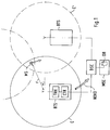
- FIG. 1 shows a situation in which the device blocks handover.
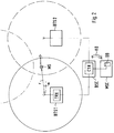
- FIG. 2 shows a situation in which the device triggers handover at an early stage.
- the SDMA mobile radio system shown schematically in FIG. 1 contains base stations BTS and BTS ', each of which supplies a radio cell C or C'.
- the base stations are connected to a base station controller BSC, which in turn is connected to a mobile switching center MSC.
- the mobile switching center MSC which contains a database DB, and the radio base station controller BSC control a handover of a mobile station MS from one radio station to the next.
- the mobile station MS is in radio communication with the base station BTS, which supplies the radio cell C.
- the base station BTS is equipped with a phase-controlled group antenna and with a radio transceiver TRX, as is known, for example, from WO 93/12590.
- the base station BTS contains a processor-controlled device CTR, which is connected to the radio transceiver TRX and, according to the invention, monitors a radio signal received by the latter, in order to determine whether the mobile station MS emitting the radio signal is moving along the edge of the radio cell C.
- the device CTR sends a blocking signal NOHO to the base station controller BSC in order to prevent the mobile station MS from being passed on to one of the neighboring radio cells, such as to the radio cell C '.
- the device continuously detects during the radio transmission between the mobile station MS and the base station BTS at predetermined time intervals of approximately 30 seconds. the signal transit time of the radio signal on the uplink channel.
- the base station BTS sends a first radio pulse to the mobile station MS. After receiving the radio pulse, this waits for a predetermined period of time dT, which is approximately 1.7 ms, and then sends a second radio pulse to the base station BTS in response.
- the continuously determined values of the signal transit time are entered in the database DB.
- the device calculates changes in the signal transit time by comparing the last determined value with the previously determined values. If the changes lie within a tolerance range of approximately 1 ⁇ s, it is assumed that the distance r between the mobile station MS and the base station BTS has not changed significantly (1 ⁇ s corresponds to approximately 300 m).
- the device CTR By monitoring the direction of reception ⁇ from which the radio signal is received by the base station BTS, the device CTR then determines that the mobile station MS is moving perpendicular to the radius of the radio cell C. In order to determine whether the mobile station is moving along the edge of the radio cell C, the device CTR evaluates the last determined amount of the signal transit time of the radio signal. If the signal propagation time determined is approximately 50 ⁇ s, the mobile station MS is located at the edge of the radio cell C, which here has a diameter of approximately 30 km
- the device then signals the blocking signal NOHO to the device that controls the handover of the mobile station MS, i. H. in this example to the base station controller BSC.
- Handover to the mobile station MS is thus interrupted as long as it is still in the edge region of the radio cell C. This avoids repeated handing over, in which the radio connection is switched back and forth within a short time. This also avoids a burden on the signaling paths in the mobile radio system.
- the device according to the invention thus evaluates the radio signal parameters r and ⁇ which are required anyway for carrying out the SDMA radio transmission. This makes the invention very easy to implement.
- continuous monitoring of the reception level can also be carried out in order to determine changes in the distance r.
- the method described above for tracking the one mobile station MS can be carried out for any mobile station that moves within the SDMA mobile radio system. It is advantageous to link the detected radio signal parameters, such as the direction of reception, reception level or signal transit time, with time indications which indicate the time of detection. All data are stored in the database DB and form the data records for a file that can be accessed during radio resource planning or redistribution. From these data sets, motion profiles can be derived that indicate at what times (days of the week, times) how distributed the subscriber density in the radio network is. To make better use of the radio resources, it is sufficient to carry out such statistical data acquisition separately and independently of the proposed radio signal monitoring and blocking the handover
- FIG. 2 schematically shows an SDMA mobile radio system which differs from the SDMA mobile radio system only as follows:
- the processor-controlled device CTR is integrated in the base station controller BSC and not in the base stations BTS1 and BTS2. This ensures that the received radio signals are monitored, i.e. monitoring the uplink radio channels at a central location in the mobile radio system.
- this central point is the radio base station controller BSC, which controls the radio channel assignment and the forwarding in the area assigned to it, the so-called BSC area.
- the conventional radio signal monitoring which is necessary anyway, is thus improved according to the invention in the BSC in order to prevent unnecessary transmission.
- the situation shown schematically here in FIG. 2 shows a moving mobile station MS which leaves the radio cell C1 in the direction of the adjacent radio cell C2.
- the processor-controlled device CTR determines that the mobile station MS is moving towards the edge of the radio cell C1.
- the device CTR determines the current position, the main direction of movement and the average speed of the mobile station MS by evaluating the movement profile data r (t) and ⁇ (t) stored in the database.
- the device CTR then calculates a point in time at which the mobile station MS is likely to reach the edge of the radio cell. At this point in time, which can also be defined by a reception level threshold, the handover of the mobile station MS is conventionally triggered.
- the device CTR signals a trigger signal HO to the forwarding control device before this time is reached.
- the device CTR sends the determined movement direction ⁇ as a trigger signal HO to the mobile radio switching center MSC, which controls the handover here.
- the device CTR sends the determined movement direction ⁇ as a trigger signal HO to the mobile radio switching center MSC, which controls the handover here.
- the direction of movement is set equal to the direction of reception ⁇ of the radio signal.
- This simplification is permissible if the radio cell radius (here, for example, 15 km) is large compared to the last determined distance between the mobile station MS and the radio cell edge (here, for example, 1 km).
- the device shown in FIG. 2 thus evaluates CTR continuously the signal transit time and the complex weighting factors of the radio signal received by the base station BTS1 in order to obtain two time functions which indicate changes in the distance r (t) and changes in the reception direction ⁇ (t). These two time functions characterize the movement profile of the mobile station MS and are sufficient to determine in which direction the mobile station MS is leaving the radio cell C1 and to initiate forwarding to the radio cell C2 closest in the direction at an early stage.
- the continuous evaluation of the signal transit time and that of the weighting factors takes place at predefinable time intervals, which decrease with an increase in the recorded signal transit time.
- the device CTR only carries out the evaluation according to the invention at short time intervals if the mobile station MS is in the edge region of the radio cell. If the mobile station MS is located in the core area of the radio cell (short signal runtime), slow monitoring (long time intervals) is sufficient. Thus, the computing effort for the processor-controlled device CTR can be reduced.
- the processor-controlled device CTR is constructed on the basis of the control electronics required in the radio base station controller BSC. It is also conceivable to implement the device by means of a personal computer which is connected to the database.
- the processor-controlled device can also be integrated into a radio switching center, in particular together with the database.
Abstract
Description
Die Erfindung betrifft eine prozessorgesteuerte Vorrichtung gemäß dem Oberbegriff des Anspruchs 1 sowie eine damit ausgestattete Funkfeststation und Funkfeststationssteuerung für ein SDMA - Mobilfunksystem (SDMA: Space Division Multiple Access).The invention relates to a processor-controlled device according to the preamble of claim 1 and a radio base station and radio base station controller equipped with it for an SDMA mobile radio system (SDMA: Space Division Multiple Access).
Eine solche Vorrichtung ist aus WO 93/12590 bekannt. Dort wird eine als SDMA-Controller bezeichnete Vorrichtung beschrieben, die ein von einer Funkfeststation empfangenes Funksignal überwacht, um eine Mobilstation zu verfolgen, die sich in einer von der Funkfeststation versorgten Funkzelle befindet und dieses Funksignal aussendet. Wie in Wo 93/12590 auf Seiten 22 bis 24 beschrieben werden zur Bestimmung des aktuellen Aufenthaltsortes der Mobilstation, die Raumrichtung DOA (Direction of Arnival), aus der das Funksignal empfangen wird, und die Ankunftszeit TOA (Time of Arrival) des Funksignals erfaßt. Der SDMA Controller erfaßt fortlaufend diese Funksignalparameter, um Probleme beim Weiterreichen der Mobilstation von einer Funkzelle zur nächsten zu mildern (s. dort S. 24, 1 Abs.). Welche Probleme wie gemildert werden wird in Wo 93/12590 nicht näher beschrieben. Auch eine Lösung des bei zellularen Funksystemen allgemein bekannten Problems, daß eine Steuerung des Weiterreichens einen instabilen Zustand einnehmen kann, sodaß die Mobilstation mehrmals zwischen zwei Funkzellen hin - und hergereicht wird, ist dort nicht beschrieben.Such a device is known from WO 93/12590. There, a device called an SDMA controller is described which monitors a radio signal received by a base station in order to track a mobile station which is located in a radio cell supplied by the base station and transmits this radio signal. As described in Wo 93/12590 on pages 22 to 24, in order to determine the current location of the mobile station, the spatial direction DOA (Direction of Arnival) from which the radio signal is received and the arrival time TOA (Time of Arrival) of the radio signal are recorded. The SDMA controller continuously records these radio signal parameters in order to alleviate problems with the handover of the mobile station from one radio cell to the next (see p. 24, 1 paragraph). Wo 93/12590 does not describe which problems are alleviated and how. Also one The solution to the problem, which is generally known in cellular radio systems, that control of the handover can assume an unstable state, so that the mobile station is passed back and forth several times between two radio cells, is not described there.
Aufgabe der Erfindung ist es, die eingangs genannte Vorrichtung so zu verbessern, daß diese die Steuerung des Weiterreichens zur Vermeidung dieses Problems unterstützt. Gelöst wird die Aufgabe durch eine prozessorgesteuerte Vorrichtung mit den Merkmalen nach Anspruch 1.The object of the invention is to improve the above-mentioned device so that it supports the control of the handover to avoid this problem. The object is achieved by a processor-controlled device having the features of claim 1.
Demnach stellt die erfindungsgemäße Vorrichtung fest, ob die Mobilstation sich im wesentlichen entlang des Randes der Funkzelle bewegt, und blockiert in einem solchen Fall das Weiterreichen der Mobilstation, indem die Vorrichtung ein Blockierungssignal an eine Einrichtung des SDMA- Mobilfunksystem signalisiert, die das Weiterreichen steuert. Dadurch wird verhindert, daß die Steuerung des Weiterreichens einen instabilen Zustand einnimmt, der zu einer erhöhten Signalisierung und damit zu einer Belastung der steuernden Einrichtung, wie etwa der Funkvermittlungsstelle, führt. Die erfindungsgemäße Vorrichtung kann durch eine einfache Erweiterung der ohnehin erforderlichen Funksignalüberwachung realisiert werden. Die Vorrichtung ist in eine Funkfeststation gemäß Anspruch 6 oder in eine Funkfeststationssteuerung gemäß Anspruch 7 integrierbar. Vorteilhafte Ausgestaltungen der Erfindung sind den Unteransprüchen zu entnehmen.Accordingly, the device according to the invention determines whether the mobile station is essentially moving along the edge of the radio cell and, in such a case, blocks the handover of the mobile station by the device signaling a blocking signal to a device of the SDMA mobile radio system which controls the handover. This prevents the handover control from taking on an unstable state, which leads to increased signaling and thus to a burden on the controlling device, such as the radio switching center. The device according to the invention can be implemented by a simple extension of the radio signal monitoring that is required anyway. The device can be integrated into a base station according to claim 6 or into a base station controller according to claim 7. Advantageous embodiments of the invention can be found in the subclaims.
Im weiteren folgt die Beschreibung eines ersten und eines zweiten Ausführungsbeispiels der Erfindung anhand der Zeichnungen, die schematisch den Aufbau eines SDMA-Mobilfunksystems darstellen, wobei
- Fig. 1 zeigt, wie die erfindungsgemäße Vorrichtung in eine Funkfeststation integriert ist, und
- Fig. 2 zeigt, wie die erfindungsgemäße Vorrichtung in eine Funkfeststationssteuerung integriert ist.
- 1 shows how the device according to the invention is integrated in a base station, and
- 2 shows how the device according to the invention is integrated into a radio base station controller.
Zudem ist in Fig. 1 eine Situation dargestellt, bei der die Vorrichtung ein Weiterreichen blockiert. In Fig. 2 hingegen ist eine Situation dargestellt, bei der die Vorrichtung ein Weiterreichen frühzeitig aus löst.In addition, a situation is shown in FIG. 1 in which the device blocks handover. 2, on the other hand, shows a situation in which the device triggers handover at an early stage.
Das in Fig. 1 schematisch dargestellte SDMA-Mobilfunksystem enthält Funkfeststationen BTS und BTS', die jeweils eine Funkzelle C bzw. C' versorgen. Die Funkfeststationen sind mit einer Funkfeststationssteuerung BSC verbunden, die wiederum mit einer Mobilfunkvermittlungsstelle MSC verbunden ist. Die Mobilfunkvermittlungsstelle MSC, die eine Datenbank DB enthält, als auch die Funkfeststationssteuerung BSC steuern ein Weiterreichen einer Mobilstation MS von einer Funkstelle zur nächsten. In diesem Beispiel ist die Mobilstation MS in Funkverbindung mit der Funkfeststation BTS, die die Funkzelle C versorgt. Die Funkfeststation BTS ist zur Durchführung einer SDMA - Funkübertragung mit einer phasengesteuerten Grupppenantenne und mit einem Funksendeempfänger TRX ausgestattet, wie er etwa aus WO 93/12590 bekannt ist. Darüberhinaus enthält die Funkfeststation BTS eine prozessorgesteuerte Vorrichtung CTR, die mit dem Funksendeempfänger TRX verbunden ist und die erfindungsgemäß ein von diesem empfangenes Funksignal überwacht, um festzustellen, ob die das Funksignal aussendene Mobilstation MS sich entlang des Randes der Funkzelle C bewegt. In einem solchen Fall sendet die Vorrichtung CTR ein Blockierungssignal NOHO an die Funkfeststationssteuerung BSC, um ein Weiterreichen der Mobilstation MS an eine der benachbarten Funkzellen, wie etwa an die Funkzelle C', zu verhindern.The SDMA mobile radio system shown schematically in FIG. 1 contains base stations BTS and BTS ', each of which supplies a radio cell C or C'. The base stations are connected to a base station controller BSC, which in turn is connected to a mobile switching center MSC. The mobile switching center MSC, which contains a database DB, and the radio base station controller BSC control a handover of a mobile station MS from one radio station to the next. In this example, the mobile station MS is in radio communication with the base station BTS, which supplies the radio cell C. To carry out an SDMA radio transmission, the base station BTS is equipped with a phase-controlled group antenna and with a radio transceiver TRX, as is known, for example, from WO 93/12590. In addition, the base station BTS contains a processor-controlled device CTR, which is connected to the radio transceiver TRX and, according to the invention, monitors a radio signal received by the latter, in order to determine whether the mobile station MS emitting the radio signal is moving along the edge of the radio cell C. In such a case, the device CTR sends a blocking signal NOHO to the base station controller BSC in order to prevent the mobile station MS from being passed on to one of the neighboring radio cells, such as to the radio cell C '.
Die Vorrichtung erfaßt während der Funkübertragung zwischen der Mobilstation MS und der Funkfeststation BTS fortlaufend in vorgegebenen Zeitabständen von etwa 30 sek. die Signallaufzeit des Funksignals auf dem Aufwärtskanal. Dazu sendet die Funkfeststation BTS einen ersten Funkimpuls an die Mobilstation MS. Diese wartet nach Empfang des Funkimpulses eine vorgegebene Zeitspanne dT, die etwa 1,7 ms beträgt, und sendet dann als Antwort einen zweiten Funkimpuls an die Funkfeststation BTS. In der Vorrichtung CTR wird nun die Signallaufzeit Tp nach folgender Gleichung ermittelt: ![]()
![]()
Die Vorrichtung signalisiert dann das Blockierungssignal NOHO an die Einrichtung, die das Weiterreichen der Mobilstation MS steuert, d. h. in diesem Beispiel an die Funkfeststationssteuerung BSC. Somit wird solange ein Weiterreichen der Mobilstation MS unterbrochen, wie diese sich noch im Randbereich der Funkzelle C aufhält. Dadurch wird ein mehrmaliges Weiterreichen vermieden, bei dem die Funkverbindung innerhalb kurzer Zeit hin - und hergeschaltet wird. Eine Belastung der Signalisierungswege im Mobilfunksystem wird ebenfalls dadurch vermieden. Die erfindungsgemäße Vorrichtung wertet somit die Funksignalparameter r und α aus, die ohnehin zur Durchführung der SDMA - Funkübertragung benötigt werden. Dadurch ist die Erfindung sehr einfach zu realisieren. Alternativ zu der oben beschriebenen Ermittelung der Signallaufzeit kann auch eine fortlaufende Überwachung des Empfangspegels durchgeführt werden, um Änderungen des Abstandes r festzustellen. Weiterhin ist es auch denkbar die Signallaufzeit und den Empfangspegel gleichfalls zu erfassen, um eine zuverlässige Überwachung des Abstandes zu erreichen.The device then signals the blocking signal NOHO to the device that controls the handover of the mobile station MS, i. H. in this example to the base station controller BSC. Handover to the mobile station MS is thus interrupted as long as it is still in the edge region of the radio cell C. This avoids repeated handing over, in which the radio connection is switched back and forth within a short time. This also avoids a burden on the signaling paths in the mobile radio system. The device according to the invention thus evaluates the radio signal parameters r and α which are required anyway for carrying out the SDMA radio transmission. This makes the invention very easy to implement. As an alternative to the determination of the signal propagation time described above, continuous monitoring of the reception level can also be carried out in order to determine changes in the distance r. Furthermore, it is also conceivable to also record the signal transit time and the reception level in order to reliably monitor the distance.
Das oben beschriebene Verfahren zur Verfolgung der einen Mobilstation MS ist für jede Mobilstation, die sich innerhalb des SDMA-Mobilfunksystem bewegt durchführbar. Dabei ist es vorteilhaft die erfaßten Funksignalparametern, wie Empfangsrichtung, Empfangspegel oder Signallaufzeit, mit Zeitangaben zu verknüpfen die den Zeitpunkt der Erfassung angeben. Alle Daten werden in der Datenbank DB abgelegt und bilden die Datensätze für eine Datei, auf die bei einer Funkresourcenplanung oder - umverteilung zugegriffen werden kann. Aus diesen Datensätzen können Bewegungsprofile abgeleitet werden, die angeben zu welchen Zeiten (Wochentagen, Uhrzeiten) die Teilnehmerdichte im Funknetz wie verteilt ist. Zur besseren Nutzung der Funkresourcen reicht es aus, eine solche statistische Datenerfassung separat und unabhängig von der vorgeschlagenen Funksignalüberwachung und Blockierung des Weiterreichens durchzuführenThe method described above for tracking the one mobile station MS can be carried out for any mobile station that moves within the SDMA mobile radio system. It is advantageous to link the detected radio signal parameters, such as the direction of reception, reception level or signal transit time, with time indications which indicate the time of detection. All data are stored in the database DB and form the data records for a file that can be accessed during radio resource planning or redistribution. From these data sets, motion profiles can be derived that indicate at what times (days of the week, times) how distributed the subscriber density in the radio network is. To make better use of the radio resources, it is sufficient to carry out such statistical data acquisition separately and independently of the proposed radio signal monitoring and blocking the handover
Ein zweites Ausführungsbeispiel wird nun anhand der Fig. 2 beschrieben, die schematisch ein SDMA-Mobilfunksystem zeigt, das sich von dem SDMA-Mobilfunksystem lediglich wie folgt unterscheidet:A second exemplary embodiment will now be described with reference to FIG. 2, which schematically shows an SDMA mobile radio system which differs from the SDMA mobile radio system only as follows:
Die prozessorgesteuerte Vorrichtung CTR ist in diesem zweiten Beispiel in die Funkfeststationssteuerung BSC und nicht in die Funkfeststationen BTS1 und BTS2 integriert. Dadurch erfolgt die Überwachung der empfangenen Funksignale, d.h. die Überwachung der Aufwärtsfunkkanäle, an einer zentralen Stelle in dem Mobilfunksystem. Diese zentrale Stelle ist in diesem Beispiel die Funkfeststationssteuerung BSC, die die Funkkanalzuweisung sowie das Weiterreichen in dem ihr zugeordneten Gebiet, der sogenannte BSC-area, steuert. Damit wird in der BSC die ohnehin notwendige herkömmliche Funksignalüberwachung erfindungsgemäß verbessert, um ein überflüssiges Weiterreichen zu verhindern.In this second example, the processor-controlled device CTR is integrated in the base station controller BSC and not in the base stations BTS1 and BTS2. This ensures that the received radio signals are monitored, i.e. monitoring the uplink radio channels at a central location in the mobile radio system. In this example, this central point is the radio base station controller BSC, which controls the radio channel assignment and the forwarding in the area assigned to it, the so-called BSC area. The conventional radio signal monitoring, which is necessary anyway, is thus improved according to the invention in the BSC in order to prevent unnecessary transmission.
Die hier in Fig. 2 schematisch dargestellte Situation zeigt eine sich bewegende Mobilstation MS, die die Funkzelle C1 in Richtung der benachbarten Funkzelle C2 verläßt. Durch die erfindungsgemäße Überwachung des von der Funkfeststation BTS1 empfangenen Funksignales, stellt die prozessorgesteuerte Vorrichtung CTR fest, daß sich die Mobilstation MS zum Rand der Funkzelle C1 hinbewegt. Die Vorrichtung CTR ermittelt durch Auswertung der in der Datenbank abgelegten Bewegungsprofil-Daten r (t) und α (t) die aktuelle Position, die Hauptbewegungsrichtung und die mittlere Geschwindigkeit der Mobilstation MS. Danach errechnet die Vorrichtung CTR einen Zeitpunkt, an dem die Mobilstation MS voraussichtlich den Rand der Funkzelle erreicht. Zu diesem Zeitpunkt, der auch durch einen Empfangspegelschwellwert definiert sein kann, wird herkömmlicherweise das Weiterreichen der Mobilstation MS ausgelöst.The situation shown schematically here in FIG. 2 shows a moving mobile station MS which leaves the radio cell C1 in the direction of the adjacent radio cell C2. By monitoring the radio signal received by the base station BTS1 according to the invention, the processor-controlled device CTR determines that the mobile station MS is moving towards the edge of the radio cell C1. The device CTR determines the current position, the main direction of movement and the average speed of the mobile station MS by evaluating the movement profile data r (t) and α (t) stored in the database. The device CTR then calculates a point in time at which the mobile station MS is likely to reach the edge of the radio cell. At this point in time, which can also be defined by a reception level threshold, the handover of the mobile station MS is conventionally triggered.
Die erfindungsgemäße Vorrichtung CTR signalisiert jedoch vor Erreichen dieses Zeitpunktes ein Auslösesignal HO an die das Weiterreichen steuernde Einrichtung. In dem Beispiel nach Fig. 2 sendet die Vorrichtung CTR als Auslösesignal HO die ermittelte Bewegungsrichtung α an die Mobilfunkvermittlungsstelle MSC, die hier das Weiterreichen steuert. In diesem Beispiel entfällt eine Berechnung der tatsächlichen Bewegungsrichtung der Mobilstation MS, d.h. eine Berechnung aufgrund der ermittelten Signallaufzeiten und/oder der Empfangspegel, indem die Bewegungsrichtung gleich der Empfangsrichtung α des Funksignals gesetzt wird. Diese Vereinfachung ist dann zulässig, wenn der Funkzellenradius (hier z.B. 15 km) groß ist gegen den zuletzt ermittelten Abstand der Mobilstation MS zum Funkzellenrand (hier z.b. 1 km). Somit wertet die in Fig. 2 dargestellte Vorrichtung CTR
fortlaufend die Signallaufzeit und die komplexen Wichtungsfaktoren des von der Funkfeststation BTS1 empfangenen Funksignals aus, um zwei Zeitfunktionen zu erhalten, die Änderungen des Abstands r (t) und Änderungen der Empfangsrichtung α (t) angeben. Diese beiden Zeitfunktionen kennzeichnen das Bewegungsprofil der Mobilstation MS und reichen aus, um festzustellen, in welcher Richtung die Mobilstation MS die Funkzelle C1 verläßt und um frühzeitig das Weiterreichen zu der in der Richtung nächstliegenden Funkzelle C2 auszulösen. Die fortlaufende Auswertung der Signallaufzeit und die der Wichtungsfaktoren erfolgt in vorgebbaren Zeitabständen, die mit einer Zunahme der erfaßten Signallaufzeit abnehmen. Hier werden bei einer Signallaufzeit von etwa 10 µs, 20 µs oder 50 µs Zeitabstände von etwa 2 Min., 1 Min. bzw. 30 sec. festgelegt. Durch diese Maßnahme führt die Vorrichtung CTR die erfindungsgemäße Auswertung nur dann in kurzen Zeitabständen aus, falls die Mobilstation MS sich im Randbereich der Funkzelle aufhält. Befindet sich die Mobilstation MS im Kernbereich der Funkzelle (kleine Signallaufzeit) ist eine langsame Überwachung (große Zeitabstände) ausreichend. Somit kann der Rechenaufwand für die prozessorgesteuerte Vorrichtung CTR reduziert werden. Die prozessorgesteuerte Vorrichtung CTR ist in diesem Beispiel auf der Grundlage der ohnehin benötigten Steuerelektronik in der Funkfeststationssteuerung BSC aufgebaut. Es ist auch denkbar die Vorrichtung mittels Personal-Computers zu realisieren, der mit der Datenbank verbunden ist.However, the device CTR according to the invention signals a trigger signal HO to the forwarding control device before this time is reached. In the example according to FIG. 2, the device CTR sends the determined movement direction α as a trigger signal HO to the mobile radio switching center MSC, which controls the handover here. In this example, there is no calculation of the actual direction of movement of the mobile station MS, ie a calculation based on the determined signal propagation times and / or the reception level, in that the direction of movement is set equal to the direction of reception α of the radio signal. This simplification is permissible if the radio cell radius (here, for example, 15 km) is large compared to the last determined distance between the mobile station MS and the radio cell edge (here, for example, 1 km). The device shown in FIG. 2 thus evaluates CTR
continuously the signal transit time and the complex weighting factors of the radio signal received by the base station BTS1 in order to obtain two time functions which indicate changes in the distance r (t) and changes in the reception direction α (t). These two time functions characterize the movement profile of the mobile station MS and are sufficient to determine in which direction the mobile station MS is leaving the radio cell C1 and to initiate forwarding to the radio cell C2 closest in the direction at an early stage. The continuous evaluation of the signal transit time and that of the weighting factors takes place at predefinable time intervals, which decrease with an increase in the recorded signal transit time. With a signal runtime of approximately 10 µs, 20 µs or 50 µs, time intervals of approximately 2 minutes, 1 minute or 30 seconds are specified. As a result of this measure, the device CTR only carries out the evaluation according to the invention at short time intervals if the mobile station MS is in the edge region of the radio cell. If the mobile station MS is located in the core area of the radio cell (short signal runtime), slow monitoring (long time intervals) is sufficient. Thus, the computing effort for the processor-controlled device CTR can be reduced. In this example, the processor-controlled device CTR is constructed on the basis of the control electronics required in the radio base station controller BSC. It is also conceivable to implement the device by means of a personal computer which is connected to the database.
Die anhand der beiden Ausführungsbeispiele beschriebene Erfindung ist auch in anderen denkbaren Varianten realisierbar. So kann die prozessorgesteuerte Vorrichtung etwa auch in eine Funkvermittlungsstelle integriert werden, insbesondere zusammen mit der Datenbank.The invention described on the basis of the two exemplary embodiments can also be implemented in other conceivable variants. For example, the processor-controlled device can also be integrated into a radio switching center, in particular together with the database.
Claims (7)
dadurch gekennzeichnet, daß
die prozessorgesteuerte Vorrichtung (CTR) mittels der Überwachung des Funksignals feststellt, ob die Mobilstation (MS) sich im wesentlichen entlang des Randes der Funkzelle (C) bewegt, und die in einem solchen Fall ein Weiterreichen der Mobilstation (MS) blockiert mittels Signalisierung eines Blockierungsignals (NOHO) an eine das Welterreichen steuernde Einrichtung (MSC) des SDMA - Mobilfunksystems.Processor-controlled device (CTR), which monitors a radio signal received by at least one base station (BTS) in an SDMA mobile radio system for tracking a mobile station (MS) which transmits this radio signal within a radio cell (C) supplied by the base station (BTS) ,
characterized in that
the processor-controlled device (CTR) uses the monitoring of the radio signal to determine whether the mobile station (MS) is essentially moving along the edge of the radio cell (C) and, in such a case, blocks the handover of the mobile station (MS) by signaling a blocking signal (NOHO) to a world-wide controlling device (MSC) of the SDMA mobile radio system.
dadurch gekennzeichnet, daß die Vorrichtung (CTR) das Funksignal mittels einer fort laufenden Erfassung dessen Empfangspegels und/oder dessen Signallaufzeit überwacht.Processor-controlled device (CTR) according to claim 1,
characterized in that the device (CTR) monitors the radio signal by means of a continuous detection of its reception level and / or its signal propagation time.
dadurch gekennzeichnet, daß die Vorrichtung (CTR) mit einer Datenbank (DB) verbindbar ist, in der sie den erfaßten Empfangspegel und/oder die Signallaufzeit zusammen mit einer Zeitangabe ablegt, die die aktuelle Uhrzeit enthält.Processor-controlled device (CTR) according to claim 2
characterized in that the device (CTR) can be connected to a database (DB) in which it stores the detected reception level and / or the signal runtime together with a time specification which contains the current time.
dadurch gekennzeichnet, daß die Vorrichtung (CTR) mittels der Überwachung des Funksignals feststellt, ob die Mobilstation (MS) sich im wesentlichen zum Rand der Funkzelle (C) hinbewegt, und die in einem solchen Fall die Bewegungsrichtung (α) feststellt und diese an die das Weiterreichen steuernde Einrichtung (MSC) signalisiert, um das Weiterreichen der Mobilstation (MS) zu der in Bewegungsrichtung nächstliegenden Funkzelle auzulösen.Processor-controlled device (CTR) according to claim 1,
characterized in that the device (CTR) uses the monitoring of the radio signal to determine whether the mobile station (MS) is essentially moving towards the edge of the radio cell (C) and which in such a case determines the direction of movement (α) and sends this to the the handover control device (MSC) signals to trigger the handover of the mobile station (MS) to the radio cell closest in the direction of movement.
dadurch gekennzeichnet, daß die Vorrichtung (CTR) die Signallaufzeit des Funksignals in vorgebbaren Zeitabständen erfaßt und die Zeitabstände verkleinert, falls die Signallaufzeit zunimmt.Processor-controlled device (CTR) according to claim 2,
characterized in that the device (CTR) detects the signal transit time of the radio signal at predeterminable time intervals and reduces the time intervals if the signal transit time increases.
dadurch gekennzeichnet, daß
die prozessorgesteuerte Vorrichtung (CTR) mittels der Überwachung des Funkksignals feststellt, ob die Mobilstation (MS) sich im wesentlichen entlang des Randes der Funkzelle (C) bewegt, und die in einem solchen Fall ein Weiterreichen der Mobilstation (MS) an eine benachbarte Funkzelle blockiert mittels Signalisierung eines Blockierungssignals (NOHO) an eine das Weiterreichen steuernde Einrichtung (MSC) des SDMA-Mobilfunksystems.Fixed base station (BTS) for an SDMA mobile radio system with a processor-controlled device (CTR) that monitors a radio signal received by the fixed base station (BTS) to track a mobile station (MS) that is inside a radio cell (C) supplied by the fixed base station (BTS) emits this radio signal,
characterized in that
the processor-controlled device (CTR) uses the monitoring of the radio signal to determine whether the mobile station (MS) is essentially moving along the edge of the radio cell (C) and, in such a case, to forward the mobile station (MS) an adjacent radio cell blocks by signaling a blocking signal (NOHO) to a forwarding control device (MSC) of the SDMA mobile radio system.
dadurch gekennzeichnet, daß
die prozessorgesteuerte Vorrichtung (CTR) mittels der Überwachung des Funksignals feststellt, ob die Mobilstation (MS) sich im wesentlichen entlang des Randes der Funkzelle (C1) bewegt, und die in einem solchen Fall ein von der Funkfeststationssteuerung (BSC) gesteuertes Weiterreichen der Mobilstation (MS) an eine benachbarte Funkzelle (C2) blockiert oder ein Blockierungssignal an eine andere das Weiterreichen steuernde Einrichtung (MSC) des SMDA - Mobilfunksystems signalisiert.Radio base station controller (BSC) for at least two radio base stations (BTS1, BTS2) within an SDMA mobile radio system with a processor-controlled device (CTR) which monitors a radio signal received by each of these radio base stations (BTS1) in order to track a mobile station (MS) operating within a radio cell (C1) supplied by the base station (BTS1) transmits this radio signal,
characterized in that
the processor-controlled device (CTR) uses the monitoring of the radio signal to determine whether the mobile station (MS) is essentially moving along the edge of the radio cell (C1), and in such a case a handover of the mobile station controlled by the radio base station controller (BSC) ( MS) to an adjacent radio cell (C2) or a blocking signal to another forwarding control device (MSC) of the SMDA mobile radio system.
Applications Claiming Priority (2)
| Application Number | Priority Date | Filing Date | Title |
|---|---|---|---|
| DE1995118399 DE19518399A1 (en) | 1995-05-19 | 1995-05-19 | Processor-controlled device for tracking a mobile station in an SDMA mobile radio system |
| DE19518399 | 1995-05-19 |
Publications (2)
| Publication Number | Publication Date |
|---|---|
| EP0743802A2 true EP0743802A2 (en) | 1996-11-20 |
| EP0743802A3 EP0743802A3 (en) | 1999-05-19 |
Family
ID=7762341
Family Applications (1)
| Application Number | Title | Priority Date | Filing Date |
|---|---|---|---|
| EP96107226A Withdrawn EP0743802A3 (en) | 1995-05-19 | 1996-05-08 | Processor controlled arrangement for mobile station tracking in a mobile radio system with space division multiple access |
Country Status (6)
| Country | Link |
|---|---|
| EP (1) | EP0743802A3 (en) |
| JP (1) | JPH08331627A (en) |
| CN (1) | CN1138283A (en) |
| AU (1) | AU698759B2 (en) |
| CA (1) | CA2176666A1 (en) |
| DE (1) | DE19518399A1 (en) |
Cited By (4)
| Publication number | Priority date | Publication date | Assignee | Title |
|---|---|---|---|---|
| WO2001089254A1 (en) * | 2000-05-15 | 2001-11-22 | Nokia Corporation | Method to calculate true round trip propagation delay and user equipment location in wcdma/utran |
| WO2004059912A1 (en) * | 2002-12-31 | 2004-07-15 | International Business Machines Corporation | Spatial boundary admission control for wireless networks |
| EP1740000A1 (en) * | 2005-06-27 | 2007-01-03 | Siemens Aktiengesellschaft | Method for handover of a radio transmission by transmission power control of the base stations |
| CN101873650B (en) * | 2009-04-24 | 2012-11-14 | 大唐移动通信设备有限公司 | Switching method and device of user equipment in spatial division multiple access |
Families Citing this family (2)
| Publication number | Priority date | Publication date | Assignee | Title |
|---|---|---|---|---|
| JP3001570B1 (en) * | 1999-02-22 | 2000-01-24 | 埼玉日本電気株式会社 | Adaptive antenna directivity control method and system |
| DE10238796B4 (en) * | 2002-08-23 | 2006-09-14 | Siemens Ag | Method for determining the position of a mobile station relative to a base station, mobile radio system and direction determination device |
Citations (2)
| Publication number | Priority date | Publication date | Assignee | Title |
|---|---|---|---|---|
| US5170485A (en) * | 1990-11-07 | 1992-12-08 | Motorola, Inc. | Hand-off algorithm for elongated radiotelephone cells |
| US5327144A (en) * | 1993-05-07 | 1994-07-05 | Associated Rt, Inc. | Cellular telephone location system |
Family Cites Families (6)
| Publication number | Priority date | Publication date | Assignee | Title |
|---|---|---|---|---|
| US4475010A (en) * | 1983-05-05 | 1984-10-02 | At&T Bell Laboratories | High density cellular mobile radio communications |
| US4654879A (en) * | 1985-03-29 | 1987-03-31 | Itt Corporation | Cellular mobile radio subscriber location detection |
| DE3685273D1 (en) * | 1985-08-02 | 1992-06-17 | Ant Nachrichtentech | METHOD FOR LOCATING MOBILE STATIONS. |
| DE3716320A1 (en) * | 1987-05-15 | 1988-11-24 | Bosch Gmbh Robert | METHOD FOR DETERMINING THE APPROXIMATE LOCATION OF A MOBILE RADIO STATION |
| US5515378A (en) * | 1991-12-12 | 1996-05-07 | Arraycomm, Inc. | Spatial division multiple access wireless communication systems |
| DE59309086D1 (en) * | 1992-08-26 | 1998-11-26 | Siemens Ag | MOBILE RADIO NETWORK |
-
1995
- 1995-05-19 DE DE1995118399 patent/DE19518399A1/en not_active Withdrawn
-
1996
- 1996-05-08 EP EP96107226A patent/EP0743802A3/en not_active Withdrawn
- 1996-05-09 AU AU52171/96A patent/AU698759B2/en not_active Ceased
- 1996-05-15 CA CA002176666A patent/CA2176666A1/en not_active Abandoned
- 1996-05-17 CN CN 96100287 patent/CN1138283A/en active Pending
- 1996-05-20 JP JP12515696A patent/JPH08331627A/en active Pending
Patent Citations (2)
| Publication number | Priority date | Publication date | Assignee | Title |
|---|---|---|---|---|
| US5170485A (en) * | 1990-11-07 | 1992-12-08 | Motorola, Inc. | Hand-off algorithm for elongated radiotelephone cells |
| US5327144A (en) * | 1993-05-07 | 1994-07-05 | Associated Rt, Inc. | Cellular telephone location system |
Non-Patent Citations (2)
| Title |
|---|
| AUSTIN M D ET AL: "DIRECTION BIASED HANDOFF ALGORITHMS FOR URBAN MICROCELLS" 8. Juni 1994 , PROCEEDINGS OF THE VEHICULAR TECHNOLOGY CONFERENCE, STOCKHOLM, JUNE 8 - 10, 1994, VOL. VOL. 1, NR. CONF. 44, PAGE(S) 101 - 105 , INSTITUTE OF ELECTRICAL AND ELECTRONICS ENGINEERS XP000496643 * Seite 102, rechte Spalte, Zeile 1 - Zeile 4 * * Seite 104, linke Spalte, Absatz IV * * |
| HALMEK H ET AL: "ZELLGRENZDETEKTION MIT RELATIVER ENTFERNUNGSMESSUNG IM NETZ C" 1. April 1986 , FUNK-TECHNIK, VOL. 41, NR. 4, PAGE(S) 146 - 149 XP002006000 * |
Cited By (5)
| Publication number | Priority date | Publication date | Assignee | Title |
|---|---|---|---|---|
| WO2001089254A1 (en) * | 2000-05-15 | 2001-11-22 | Nokia Corporation | Method to calculate true round trip propagation delay and user equipment location in wcdma/utran |
| US6681099B1 (en) | 2000-05-15 | 2004-01-20 | Nokia Networks Oy | Method to calculate true round trip propagation delay and user equipment location in WCDMA/UTRAN |
| WO2004059912A1 (en) * | 2002-12-31 | 2004-07-15 | International Business Machines Corporation | Spatial boundary admission control for wireless networks |
| EP1740000A1 (en) * | 2005-06-27 | 2007-01-03 | Siemens Aktiengesellschaft | Method for handover of a radio transmission by transmission power control of the base stations |
| CN101873650B (en) * | 2009-04-24 | 2012-11-14 | 大唐移动通信设备有限公司 | Switching method and device of user equipment in spatial division multiple access |
Also Published As
| Publication number | Publication date |
|---|---|
| EP0743802A3 (en) | 1999-05-19 |
| JPH08331627A (en) | 1996-12-13 |
| CA2176666A1 (en) | 1996-11-20 |
| CN1138283A (en) | 1996-12-18 |
| AU698759B2 (en) | 1998-11-05 |
| AU5217196A (en) | 1996-11-28 |
| DE19518399A1 (en) | 1996-11-21 |
Similar Documents
| Publication | Publication Date | Title |
|---|---|---|
| DE69838283T2 (en) | Channel allocation method for mobile communication system with space multiple access | |
| DE4294394B4 (en) | Call access method and apparatus in a cellular mobile radiotelephone system | |
| EP1494048B1 (en) | Light curtain | |
| DE60320020T2 (en) | SYSTEM AND METHOD OF EXITING A DECISION FROM A COMPETENT WIRELESS COMMUNICATIONS NETWORK | |
| EP0729285A2 (en) | Carrier frequency allocation in a SDMA radio system | |
| DE602005000166T2 (en) | Choice of base station antennas for a "synchronized set" and an "active set" | |
| EP0585994A2 (en) | Mobile radio system with adaptive channel allocation | |
| DE19580718C2 (en) | Handover procedure in a cellular communication system | |
| EP0627718A1 (en) | Method for wireless data exchange between a fixed station and moving objects, especially vehicles | |
| DE3619369A1 (en) | METHOD FOR DETERMINING THE TARGET AND Dwell Mode of a TWS RADAR SYSTEM | |
| EP1149306A1 (en) | Method for detecting targets and for determining their direction for a radar device in a motor vehicle | |
| EP0743802A2 (en) | Processor controlled arrangement for mobile station tracking in a mobile radio system with space division multiple access | |
| EP0756807B1 (en) | Hierarchical mobile radio telephone system and a handover process | |
| DE69938233T2 (en) | PROCESS FOR TRANSFERRING | |
| DE69731125T2 (en) | Cordless device, control method and system for protected locations with interference parameters corresponding to operation | |
| DE2654785A1 (en) | CIRCUIT ARRANGEMENT FOR SCANNING A TIME-LIMITED INPUT SIGNAL | |
| EP0830043A1 (en) | Base station and method for cell coverage in a mobile cellular radio system | |
| EP2322003B1 (en) | Methods, apparatuses and computer program product for computer-aided classification of measurements and for feature-based positioning of a mobile object in a predetermined region | |
| DE4441056A1 (en) | Distance determination method | |
| DE19714743C5 (en) | Method and device for the spatial assignment of quality parameters in digital mobile communication systems | |
| EP0582344B1 (en) | Cellular mobile radio system with partial cells | |
| EP0058934B1 (en) | Radio monitoring system | |
| DE2106035B2 (en) | Device for checking the conformity of the shape of an electromagnetically generated object image with a predetermined scheme | |
| EP1745674B1 (en) | Method for locating a mobile radio terminal in a mobile radio network | |
| DE2815670C2 (en) |
Legal Events
| Date | Code | Title | Description |
|---|---|---|---|
| PUAI | Public reference made under article 153(3) epc to a published international application that has entered the european phase |
Free format text: ORIGINAL CODE: 0009012 |
|
| AK | Designated contracting states |
Kind code of ref document: A2 Designated state(s): DE ES FI FR GB IT SE |
|
| PUAL | Search report despatched |
Free format text: ORIGINAL CODE: 0009013 |
|
| AK | Designated contracting states |
Kind code of ref document: A3 Designated state(s): DE ES FI FR GB IT SE |
|
| 17P | Request for examination filed |
Effective date: 19990706 |
|
| 17Q | First examination report despatched |
Effective date: 20030220 |
|
| STAA | Information on the status of an ep patent application or granted ep patent |
Free format text: STATUS: THE APPLICATION IS DEEMED TO BE WITHDRAWN |
|
| 18D | Application deemed to be withdrawn |
Effective date: 20021203 |