EP0678228B1 - Position correction method and apparatus for a vehicle navigation system - Google Patents
Position correction method and apparatus for a vehicle navigation system Download PDFInfo
- Publication number
- EP0678228B1 EP0678228B1 EP94906016A EP94906016A EP0678228B1 EP 0678228 B1 EP0678228 B1 EP 0678228B1 EP 94906016 A EP94906016 A EP 94906016A EP 94906016 A EP94906016 A EP 94906016A EP 0678228 B1 EP0678228 B1 EP 0678228B1
- Authority
- EP
- European Patent Office
- Prior art keywords
- landmark
- vehicle
- vehicle position
- distance
- heading
- Prior art date
- Legal status (The legal status is an assumption and is not a legal conclusion. Google has not performed a legal analysis and makes no representation as to the accuracy of the status listed.)
- Expired - Lifetime
Links
Images


Classifications
-
- H—ELECTRICITY
- H04—ELECTRIC COMMUNICATION TECHNIQUE
- H04B—TRANSMISSION
- H04B7/00—Radio transmission systems, i.e. using radiation field
- H04B7/14—Relay systems
- H04B7/15—Active relay systems
- H04B7/185—Space-based or airborne stations; Stations for satellite systems
-
- G—PHYSICS
- G01—MEASURING; TESTING
- G01C—MEASURING DISTANCES, LEVELS OR BEARINGS; SURVEYING; NAVIGATION; GYROSCOPIC INSTRUMENTS; PHOTOGRAMMETRY OR VIDEOGRAMMETRY
- G01C21/00—Navigation; Navigational instruments not provided for in groups G01C1/00 - G01C19/00
- G01C21/26—Navigation; Navigational instruments not provided for in groups G01C1/00 - G01C19/00 specially adapted for navigation in a road network
- G01C21/28—Navigation; Navigational instruments not provided for in groups G01C1/00 - G01C19/00 specially adapted for navigation in a road network with correlation of data from several navigational instruments
- G01C21/30—Map- or contour-matching
-
- G—PHYSICS
- G01—MEASURING; TESTING
- G01S—RADIO DIRECTION-FINDING; RADIO NAVIGATION; DETERMINING DISTANCE OR VELOCITY BY USE OF RADIO WAVES; LOCATING OR PRESENCE-DETECTING BY USE OF THE REFLECTION OR RERADIATION OF RADIO WAVES; ANALOGOUS ARRANGEMENTS USING OTHER WAVES
- G01S19/00—Satellite radio beacon positioning systems; Determining position, velocity or attitude using signals transmitted by such systems
- G01S19/01—Satellite radio beacon positioning systems transmitting time-stamped messages, e.g. GPS [Global Positioning System], GLONASS [Global Orbiting Navigation Satellite System] or GALILEO
- G01S19/13—Receivers
- G01S19/24—Acquisition or tracking or demodulation of signals transmitted by the system
-
- G—PHYSICS
- G01—MEASURING; TESTING
- G01S—RADIO DIRECTION-FINDING; RADIO NAVIGATION; DETERMINING DISTANCE OR VELOCITY BY USE OF RADIO WAVES; LOCATING OR PRESENCE-DETECTING BY USE OF THE REFLECTION OR RERADIATION OF RADIO WAVES; ANALOGOUS ARRANGEMENTS USING OTHER WAVES
- G01S19/00—Satellite radio beacon positioning systems; Determining position, velocity or attitude using signals transmitted by such systems
- G01S19/38—Determining a navigation solution using signals transmitted by a satellite radio beacon positioning system
- G01S19/39—Determining a navigation solution using signals transmitted by a satellite radio beacon positioning system the satellite radio beacon positioning system transmitting time-stamped messages, e.g. GPS [Global Positioning System], GLONASS [Global Orbiting Navigation Satellite System] or GALILEO
- G01S19/40—Correcting position, velocity or attitude
-
- G—PHYSICS
- G01—MEASURING; TESTING
- G01S—RADIO DIRECTION-FINDING; RADIO NAVIGATION; DETERMINING DISTANCE OR VELOCITY BY USE OF RADIO WAVES; LOCATING OR PRESENCE-DETECTING BY USE OF THE REFLECTION OR RERADIATION OF RADIO WAVES; ANALOGOUS ARRANGEMENTS USING OTHER WAVES
- G01S19/00—Satellite radio beacon positioning systems; Determining position, velocity or attitude using signals transmitted by such systems
- G01S19/01—Satellite radio beacon positioning systems transmitting time-stamped messages, e.g. GPS [Global Positioning System], GLONASS [Global Orbiting Navigation Satellite System] or GALILEO
- G01S19/13—Receivers
- G01S19/24—Acquisition or tracking or demodulation of signals transmitted by the system
- G01S19/26—Acquisition or tracking or demodulation of signals transmitted by the system involving a sensor measurement for aiding acquisition or tracking
Definitions
- This invention relates to a method and apparatus for determining absolute vehicle position in vehicle navigation systems.
- a vehicle's position is determined through the accumulation of data gathered by various navigation sensors.
- Typical navigation sensors include compasses to measure the absolute vehicle heading relative to the earth's magnetic field; gyroscopes and differential odometers to measure the vehicle's relative heading; and odometers to measure the absolute distance traveled by the vehicle. Errors in vehicle position result from the accumulation of measurement errors by each of the sensors. Compass measurements are affected by magnetic anomalies such as steel bridges or buildings. Gyroscopes and differential odometers tend to have higher resolution, but their outputs are subject to drifting phenomena. As these measurement errors accumulate, the error in the vehicle position calculated by the navigation system increases.
- Map matching uses geometrical similarities in its decision making process.
- the navigation system compares the current vehicle trajectory to street geometries near the currently stored vehicle position. The system then corrects the vehicle position to the location which most closely matches the vehicle's trajectory.
- the system searches its internal map data base in the vicinity of the most recently calculated vehicle position to find street candidates which lie in the direction in which the vehicle is currently headed.
- the vehicle's heading, speed, and distance traveled are continuously monitored and compared to the geometry of the current "list" of street candidates. As the geometry of each street diverges from the vehicle's calculated trajectory, that street is eliminated as a possible location. This process continues until all streets are eliminated except one. That street is then stored as the current location of the vehicle.
- Map matching has proven to be an effective position error correction technique in an urban environment.
- the nature of city streets provides a constant flow of information from the navigation sensors to the system because of the distinct character of the vehicle's trajectory.
- the relatively high number of significant navigation events e.g., turns
- the short distances between such events result in a relatively accurate calculation of the vehicle's trajectory and thus a good approximation of the vehicle's absolute position.
- map matching has been shown to be inadequate for correcting vehicle position errors on freeways and rural highways.
- a vehicle can travel a great distance without the occurrence of any significant navigation events.
- the infrequent occurrence of the navigation events which are required for a map matching technique to make its decision means that position corrections will rarely be calculated. Given this fact and the continuous accumulation of errors from the navigation sensors, it becomes apparent that the errors in the calculated position of the vehicle will eventually become too large for map matching to correct.
- Error correction can also be achieved through the use of a global positioning system (GPS).
- GPS global positioning system
- satellites and ground based receivers GPS is capable of determining a vehicle's absolute position which can then be used to correct position errors made by vehicle navigation systems.
- the accuracy of GPS is dramatically affected by satellite geometry and selective availability degradation. Errors as great as a few hundred meters are not uncommon. Thus, GPS is not an entirely reliable method of position error correction.
- JP-A-63066411 discloses a hybrid position measuring means composed of a global positioning system (GPS) receiver, a range sensor, a bearing sensor and a CPU.
- GPS global positioning system
- the present vehicle position is obtained while correcting an assumed position obtained by integrating a unit running vector by the necessary means based on a position measured by a radio wave.
- a vehicle path guide is conducted by path guide means by using the measured present position.
- tunnel position storage means stores a tunnel position on map coordinates.
- Tunnel position detecting means detects the entry of a vehicle into a tunnel. Then, by correcting the assumed position by present position correcting means based on a tunnel position, effective path guide can be performed.
- EP 0352332 discloses a vehicle navigation system which compares the distance from a preceding crossing or a conspicuous object to another conspicuous object with a value from a distance sensor and clears the remaining distance to another conspicuous object to zero if the difference is below a predetermined value and the passing conspicuous object is detected by a radar or a road surface sensor. Accordingly, whenever a passing conspicuous object is detected, a distance detection error is corrected and therefore even when the distance to the next turning crossing is long, an accurate driving distance can be obtained and the present position can be detected correctly.
- EP 0485132 discloses a navigation system containing a direction sensor.
- the direction sensor has an earth magnetism sensor and a rate gyro sensor that calculates a compensated direction by weighted means process of outputs from the earth magnetism sensor and the rate gyro sensor.
- the compensated direction has a high detection accuracy similar to the rate gyro sensor in a short time, but does not have an error accumulation of the rate gyro sensor in a long time because the rate gyro sensor is substantially calibrated with the accurate direction obtained by averaging outputs of the earth magnetism sensor.
- the navigation system has distribution information of the magnetic disturbances to earth magnetism on a map and it reduces the weighted mean ratio to the earth magnetism sensor when the magnetic disturbance at locating position is large.
- the accuracy of the compensated direction is further improved by excluding inaccurate outputs of the earth magnetism sensor.
- JP-A-01 035 314 discloses a vehicle navigation system using a position sensor together with map data means for detecting the current position of the vehicle.
- a magnetic sensor detects the presence of a specific structure and a structure specifying means specifies the real position of this structure.
- a position correcting means corrects the current position of the position sensor to the real position of the structure.
- a method and apparatus are needed for the determination of vehicle position in vehicle navigation systems which are capable of reliably correcting vehicle position error while operating on freeways or rural highways.
- a vehicle navigation system and method according to Claims 1 and 6 determine the absolute position of vehicle with improved accuracy over simple map matching techniques.
- the system uses the signal output of a geomagnetic field sensor (e.g., compass) to detect perturbations caused by landmarks such as bridges, tunnels, overpasses, or geologic formations.
- a geomagnetic field sensor e.g., compass
- the compass signal output is compared to the signal output of a relative heading sensor such as a gyroscope to identify changes in the compass output caused by these landmarks rather than actual changes in heading.
- a relative heading sensor such as a gyroscope
- the difference in compass and gyroscope heading signals are filtered using a digital, auto-regressive moving-average filter of the form: where:
- the system is also capable of recalibrating its distance measurement, apparatus using the distance between two sensed landmarks as stored in the map data base.
- the system uses its distance measurement apparatus (e.g., odometer) to measure the distance from one landmark sensing event to another.
- the system's processor after it has identified the landmarks, can compare the measured distance to the distance stored in the map data base between the two events. The ratio of these two quantities can then be used to correct for any future errors in distance measurement.
- the present invention enables a vehicle navigation system to more accurately determine vehicle position in situations wherein the vehicle may travel great distances without any significant deviation in the vehicle's trajectory.
- the present invention provides a vehicle navigation system which uses a map matching technique in conjunction with magnetic anomaly detection for determining vehicle position.
- this embodiment calculates a distance calibration factor to achieve more accurate distance measurement for subsequent navigation.
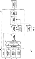
- vehicle navigation system 10 includes a plurality of sensors for determining vehicle position, including a distance sensor 12, angular velocity sensor 14 and geomagnetic sensor 16.
- the distance sensor 12 comprises an odometer
- the angular velocity sensor 14 comprises a gyroscope, or a differential odometer coupled to the wheels of the vehicle
- the geomagnetic sensor 16 usually comprises a magnetic compass mounted in the vehicle.
- a global positioning system (GPS) data receiver 18 is provided for receiving signals from, for example, a satellite-based navigation system.
- GPS global positioning system
- Data from sensors 12-16 is fed to the computing means 20, and adjusted to compensate for sensor measurement errors in the calibration means 22.
- Sensor calibration methods are described in US-A-5 345 382 entitled “CALIBRATION METHOD FOR A RELATIVE HEADING SENSOR.”
- the calibrated sensor data is transmitted to the signal processing means 24, which uses the sensor measurement data to calculate a vector describing the travel of the vehicle from a previously determined position to the measured position. This vector is then used to determine a dead-reckoned position of the vehicle by dead-reckoning means 26.
- the dead-reckoned position is then forwarded to map matching means 28, which compares the dead-reckoned position to a map data base 30.
- the map data base 30 preferably comprises positional data such as, for example, latitude and longitude coordinates, to describe road intersections, road segments, landmarks, and points of interest, and other geographical information.
- the data base 30 may further comprise data representing characteristics of roads or places on the map, such as road and place names, road features such as dividers, one-way restrictions, surface, speed limit, shape, elevation, and other properties.
- the data typically is stored in digital form on a storage medium such as an optical disk, magnetic disk or integrated circuit.
- vehicle positioning module 28 uses the data stored in data base 30, to generate one or more possible positions of the vehicle by comparing the dead-reckoned position to the road segments, intersections, and other geographical locations stored in the data base 30. The position possibilities are then provided to the route guidance module 36. The route guidance module 36 filters the set of position possibilities and selects from the remaining position possibilities a position deemed to be the current position of the vehicle.
- Fig. 3 is a flowchart 60 illustrating the GPS signal availability technique of the example.
- the system continuously checks for the availability of GPS signals (62). When GPS becomes unavailable, the system then checks if it was available for an arbitrary pas period (64) (3 seconds is used as an example). This step serves to filter out false detection events such as signal blockages caused by nearby trucks.
- the system checks the map data base in the vicinity of the last known vehicle position for the existence of an overpass which would explain sudden loss of GPS (66). If such an overpass exists within a reasonable distance, the system then concludes that the vehicle has passed under that overpass and the vehicle's position is reset to the position of the overpass (68).
- GPS signals are unavailable for extended periods of time. Additionally, if a vehicle passes under a tree or drives near a large truck the GPS signals may be blocked resulting in a false indication of an overpass. Because the above described technique is ultimately dependent upon the continued presence of GPS signals, it is frequently desirable to utilise an additional sensing scheme in parallel.
- One such scheme involves the use of the navigation system's compass as a kind of magnetometer to sense perturbations in the earth's magnetic field due to local phenomena, such as freeway overpasses, which are largely constructed of steel.
- Compass measurements are known to be affected by local magnetic anomalies and often exhibit high frequency noise as a result of such anomalies.
- By comparing the compass measurements with relative heading measurements obtained from the system's gyroscope or differential odometer it is possible to detect this high frequency noise.
- the system can then proceed to determine the absolute position of the vehicle using the most recently calculated vehicle position and its internal map.
- the vehicle navigation system 10 uses the magnetic detection of freeway overpasses to more accurately determine vehicle position.
- a navigation system's compass exhibits high frequency noise in the vicinity of landmarks causing large magnetic anomalies such as bridges, overpasses, tunnels, geologic formations, and other structures with magnetic properties.
- the system 10 compares data from its compass (e.g., geomagnetic sensor 16) and gyroscope (e.g., angular velocity sensor 14) and calculates a magnetic anomaly index. Sharp increases in the magnetic anomaly index indicate the presence of a landmark.
- Fig. 4 is a flowchart 70 of the method by which the system calculates the magnetic anomaly index.
- the system samples both the compass signal and the gyroscope signal at appropriate intervals (e.g., every 0.5 seconds).
- the gyroscope only measures the relative displacement of the vehicle, the gyroscope signal cannot be directly compared to the compass heading measurement. Instead, the system calculates the differential compass heading (rel_compass) by subtracting the previous compass signal from the current compass signal (72).
- the difference between the differential compass heading and the gyroscope measurement (74) will be large because of the high amplitude noise in the compass signal.
- DSP digital signal processing
- the system uses an auto-regressive, moving-average (ARMA) filter, although other digital filter types may be used to generate an appropriate magnetic anomaly index (78).
- ARMA auto-regressive, moving-average
- the ARMA filter has the following form: where:
- Fig. 5 is a flow chart 80 illustrating the distance calibration technique carried out in a preferred embodiment.
- the system sets a distance accumulation variable, L, to zero (84). The system then continuously updates L, storing the accumulated travel distance from the last reset (86). Upon the detection of a second overpass (88). the system compares the distance traveled. as represented by L. with the known distance between the two overpasses. L1, as stored in the system internal map (90). The ratio L ⁇ L1 can then be used to adjust subsequent distance measurements (92).
- the user may select a desired destination which is input through user interface 34, typically comprising a keyboard.
- Route guidance module 36 compares the selected destination with the data in database 30 and identifies the selected destination among the map data. Route guidance module 36 then calculates an optimum route between the initial position of the vehicle and the desired destination, taking account of distances, road speeds, one-way streets. and. in some embodiments, variable data such as traffic information or road construction work.
- the selected route comprises a set of data representing the road segments, intersections, building structures, and geographical features between the initial position of the vehicle and the desired destination.
- the current vehicle position selected from the position possibilities provided by vehicle positioning means 28 is compared to the data making up the selected route. to locate the position of the vehicle with respect to the route.
- an output commumcauon means 32 which may comprise a display screen or an audio speaker.
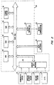
- Fig. 2 schematically illustrates an exemplary embodiment of the hardware of computing means 20.
- Sensors 12 to 16 and GPS receiver 18 are coupled to computing means 20 through sensor/GPS interface 40.
- Data from interface 40 is transmitted to CPU 42, which performs the calibration, signal processing, dead-reckoning, vehicle positioning, and route guidance functions described above.
- Data base 30 may be stored in storage medium 48, with software directing the operation of computing means 20 stored in ROM 44 for execution by CPU 42.
- RAM 46 permits reading and writing of the information necessary to execute such software programs.
- Storage medium 48 may comprise a hard disk drive. CD-ROM or integrated circuit onto which digitized map information has been stored.
- Output controller 52 which may comprise a graphics controller for a display screen, receives data processed by CPU 42 and transmits such data to output communicator 32, usually comprising a display screen.
- the user may input data, such as a desired destination, through user interface 34, typically comprising a keyboard.
Abstract
Description
- This invention relates to a method and apparatus for determining absolute vehicle position in vehicle navigation systems.
- In vehicle navigation systems, a vehicle's position is determined through the accumulation of data gathered by various navigation sensors. Typical navigation sensors include compasses to measure the absolute vehicle heading relative to the earth's magnetic field; gyroscopes and differential odometers to measure the vehicle's relative heading; and odometers to measure the absolute distance traveled by the vehicle. Errors in vehicle position result from the accumulation of measurement errors by each of the sensors. Compass measurements are affected by magnetic anomalies such as steel bridges or buildings. Gyroscopes and differential odometers tend to have higher resolution, but their outputs are subject to drifting phenomena. As these measurement errors accumulate, the error in the vehicle position calculated by the navigation system increases.
- In the past, a technique known as "map matching" has been used to correct vehicle position errors which result from the accumulation of navigation sensor errors. Map matching uses geometrical similarities in its decision making process. The navigation system compares the current vehicle trajectory to street geometries near the currently stored vehicle position. The system then corrects the vehicle position to the location which most closely matches the vehicle's trajectory.
- To accomplish this, the system searches its internal map data base in the vicinity of the most recently calculated vehicle position to find street candidates which lie in the direction in which the vehicle is currently headed. The vehicle's heading, speed, and distance traveled are continuously monitored and compared to the geometry of the current "list" of street candidates. As the geometry of each street diverges from the vehicle's calculated trajectory, that street is eliminated as a possible location. This process continues until all streets are eliminated except one. That street is then stored as the current location of the vehicle.
- Map matching has proven to be an effective position error correction technique in an urban environment. The nature of city streets provides a constant flow of information from the navigation sensors to the system because of the distinct character of the vehicle's trajectory. In essence, the relatively high number of significant navigation events (e.g., turns) and the short distances between such events result in a relatively accurate calculation of the vehicle's trajectory and thus a good approximation of the vehicle's absolute position.
- However, map matching has been shown to be inadequate for correcting vehicle position errors on freeways and rural highways. On a freeway, for example, a vehicle can travel a great distance without the occurrence of any significant navigation events. The infrequent occurrence of the navigation events which are required for a map matching technique to make its decision means that position corrections will rarely be calculated. Given this fact and the continuous accumulation of errors from the navigation sensors, it becomes apparent that the errors in the calculated position of the vehicle will eventually become too large for map matching to correct.
- Error correction can also be achieved through the use of a global positioning system (GPS). Through the use of satellites and ground based receivers, GPS is capable of determining a vehicle's absolute position which can then be used to correct position errors made by vehicle navigation systems. However, the accuracy of GPS is dramatically affected by satellite geometry and selective availability degradation. Errors as great as a few hundred meters are not uncommon. Thus, GPS is not an entirely reliable method of position error correction.
- JP-A-63066411 discloses a hybrid position measuring means composed of a global positioning system (GPS) receiver, a range sensor, a bearing sensor and a CPU. In use, the present vehicle position is obtained while correcting an assumed position obtained by integrating a unit running vector by the necessary means based on a position measured by a radio wave. A vehicle path guide is conducted by path guide means by using the measured present position. On the other hand, tunnel position storage means stores a tunnel position on map coordinates. Tunnel position detecting means detects the entry of a vehicle into a tunnel. Then, by correcting the assumed position by present position correcting means based on a tunnel position, effective path guide can be performed.
- EP 0352332 discloses a vehicle navigation system which compares the distance from a preceding crossing or a conspicuous object to another conspicuous object with a value from a distance sensor and clears the remaining distance to another conspicuous object to zero if the difference is below a predetermined value and the passing conspicuous object is detected by a radar or a road surface sensor. Accordingly, whenever a passing conspicuous object is detected, a distance detection error is corrected and therefore even when the distance to the next turning crossing is long, an accurate driving distance can be obtained and the present position can be detected correctly.
- EP 0485132 discloses a navigation system containing a direction sensor. The direction sensor has an earth magnetism sensor and a rate gyro sensor that calculates a compensated direction by weighted means process of outputs from the earth magnetism sensor and the rate gyro sensor. The compensated direction has a high detection accuracy similar to the rate gyro sensor in a short time, but does not have an error accumulation of the rate gyro sensor in a long time because the rate gyro sensor is substantially calibrated with the accurate direction obtained by averaging outputs of the earth magnetism sensor. The navigation system has distribution information of the magnetic disturbances to earth magnetism on a map and it reduces the weighted mean ratio to the earth magnetism sensor when the magnetic disturbance at locating position is large. The accuracy of the compensated direction is further improved by excluding inaccurate outputs of the earth magnetism sensor.
- JP-A-01 035 314 discloses a vehicle navigation system using a position sensor together with map data means for detecting the current position of the vehicle. A magnetic sensor detects the presence of a specific structure and a structure specifying means specifies the real position of this structure. A position correcting means corrects the current position of the position sensor to the real position of the structure.
- Therefore, a method and apparatus are needed for the determination of vehicle position in vehicle navigation systems which are capable of reliably correcting vehicle position error while operating on freeways or rural highways.
- According to the invention, a vehicle navigation system and method according to Claims 1 and 6 determine the absolute position of vehicle with improved accuracy over simple map matching techniques.
- In the preferred embodiment, the system uses the signal output of a geomagnetic field sensor (e.g., compass) to detect perturbations caused by landmarks such as bridges, tunnels, overpasses, or geologic formations. The compass signal output is compared to the signal output of a relative heading sensor such as a gyroscope to identify changes in the compass output caused by these landmarks rather than actual changes in heading. Preferably, the difference in compass and gyroscope heading signals are filtered using a digital, auto-regressive moving-average filter of the form:where:

- y(k) is the magnetic anomaly index;
- k is the current sample time;
- ai are auto-regressive coefficients;
- bj are moving-average coefficients:
- m is the number of past y(k) values included in the present value; typically m = 1;
- n is the number of present and past values of the filter input are to be averaged; typically n = 4; and
- u(k) is the difference between the compass signal and the gyroscope signal, the input to the ARMA filter.
-
- The system is also capable of recalibrating its distance measurement, apparatus using the distance between two sensed landmarks as stored in the map data base. The system uses its distance measurement apparatus (e.g., odometer) to measure the distance from one landmark sensing event to another. The system's processor, after it has identified the landmarks, can compare the measured distance to the distance stored in the map data base between the two events. The ratio of these two quantities can then be used to correct for any future errors in distance measurement.
- Accordingly, the present invention enables a vehicle navigation system to more accurately determine vehicle position in situations wherein the vehicle may travel great distances without any significant deviation in the vehicle's trajectory.
-
- Fig. 1 is a schematic diagram showing data flow in a vehicle navigation system constructed in accordance with the invention.
- Fig. 2 is a schematic diagram of a vehicle navigation system constructed in accordance with the invention.
- Fig. 3 is a flowchart representing the use of a global positioning system to determine vehicle position.
- Fig. 4 is a flowchart representing the process by which a magnetic anomaly index is calculated by the navigation system.
- Fig. 5 is a flowchart representing the use of overpass detection data to calibrate the distance measuring apparatus of the navigation system.
-
- In the preferred embodiment, the present invention provides a vehicle navigation system which uses a map matching technique in conjunction with magnetic anomaly detection for determining vehicle position. In addition, by measuring the distance travelled between two external landmarks and comparing this distance to its internal map, this embodiment calculates a distance calibration factor to achieve more accurate distance measurement for subsequent navigation.
- Vehicle navigation systems employing map matching techniques are described in US-A-5 359 529 entitled "ROUTE GUIDANCE ON/OFF-ROUTE STATE FILTER."
- Figs. 1 and 2 schematically illustrate an exemplary embodiment of a
vehicle navigation system 10. Referring first to Fig. 1,vehicle navigation system 10 includes a plurality of sensors for determining vehicle position, including adistance sensor 12,angular velocity sensor 14 andgeomagnetic sensor 16. In typical embodiments, thedistance sensor 12 comprises an odometer; theangular velocity sensor 14 comprises a gyroscope, or a differential odometer coupled to the wheels of the vehicle; and thegeomagnetic sensor 16 usually comprises a magnetic compass mounted in the vehicle. A global positioning system (GPS)data receiver 18 is provided for receiving signals from, for example, a satellite-based navigation system. - Data from sensors 12-16 is fed to the computing means 20, and adjusted to compensate for sensor measurement errors in the calibration means 22. Sensor calibration methods are described in US-A-5 345 382 entitled "CALIBRATION METHOD FOR A RELATIVE HEADING SENSOR." The calibrated sensor data is transmitted to the signal processing means 24, which uses the sensor measurement data to calculate a vector describing the travel of the vehicle from a previously determined position to the measured position. This vector is then used to determine a dead-reckoned position of the vehicle by dead-reckoning means 26. The dead-reckoned position is then forwarded to map matching means 28, which compares the dead-reckoned position to a
map data base 30. - The
map data base 30 preferably comprises positional data such as, for example, latitude and longitude coordinates, to describe road intersections, road segments, landmarks, and points of interest, and other geographical information. Thedata base 30 may further comprise data representing characteristics of roads or places on the map, such as road and place names, road features such as dividers, one-way restrictions, surface, speed limit, shape, elevation, and other properties. The data typically is stored in digital form on a storage medium such as an optical disk, magnetic disk or integrated circuit. - Using the data stored in
data base 30,vehicle positioning module 28 generates one or more possible positions of the vehicle by comparing the dead-reckoned position to the road segments, intersections, and other geographical locations stored in thedata base 30. The position possibilities are then provided to theroute guidance module 36. Theroute guidance module 36 filters the set of position possibilities and selects from the remaining position possibilities a position deemed to be the current position of the vehicle. - In addition to the above described method of determining position, the exemplary embodiment of
vehicle navigation system 10 uses data from theGPS receiver 18 to provide a more accurate determination of vehicle position on freeways, rural highways, and other locales where there are fewer road, intersections, or landmarks by which to adjust vehicle position. Fig. 3 is aflowchart 60 illustrating the GPS signal availability technique of the example. At the beginning of the process, the system continuously checks for the availability of GPS signals (62). When GPS becomes unavailable, the system then checks if it was available for an arbitrary pas period (64) (3 seconds is used as an example). This step serves to filter out false detection events such as signal blockages caused by nearby trucks. If GPS was available for the pas period, but is currently unavailable, the system then checks the map data base in the vicinity of the last known vehicle position for the existence of an overpass which would explain sudden loss of GPS (66). If such an overpass exists within a reasonable distance, the system then concludes that the vehicle has passed under that overpass and the vehicle's position is reset to the position of the overpass (68). - In some environments, there may be a possibility that GPS signals are unavailable for extended periods of time. Additionally, if a vehicle passes under a tree or drives near a large truck the GPS signals may be blocked resulting in a false indication of an overpass. Because the above described technique is ultimately dependent upon the continued presence of GPS signals, it is frequently desirable to utilise an additional sensing scheme in parallel.
- One such scheme involves the use of the navigation system's compass as a kind of magnetometer to sense perturbations in the earth's magnetic field due to local phenomena, such as freeway overpasses, which are largely constructed of steel. Compass measurements are known to be affected by local magnetic anomalies and often exhibit high frequency noise as a result of such anomalies. By comparing the compass measurements with relative heading measurements obtained from the system's gyroscope or differential odometer, it is possible to detect this high frequency noise. As with the GPS sensing scheme, once the magnetic anomaly has been detected, the system can then proceed to determine the absolute position of the vehicle using the most recently calculated vehicle position and its internal map.
- Referring again to Fig. 1 in the preferred embodiment, the
vehicle navigation system 10 uses the magnetic detection of freeway overpasses to more accurately determine vehicle position. As discussed above, a navigation system's compass exhibits high frequency noise in the vicinity of landmarks causing large magnetic anomalies such as bridges, overpasses, tunnels, geologic formations, and other structures with magnetic properties. Thesystem 10 compares data from its compass (e.g., geomagnetic sensor 16) and gyroscope (e.g., angular velocity sensor 14) and calculates a magnetic anomaly index. Sharp increases in the magnetic anomaly index indicate the presence of a landmark. - Fig. 4 is a
flowchart 70 of the method by which the system calculates the magnetic anomaly index. The system samples both the compass signal and the gyroscope signal at appropriate intervals (e.g., every 0.5 seconds). However, because the gyroscope only measures the relative displacement of the vehicle, the gyroscope signal cannot be directly compared to the compass heading measurement. Instead, the system calculates the differential compass heading (rel_compass) by subtracting the previous compass signal from the current compass signal (72). When the vehicle is in the vicinity of a magnetic anomaly, the difference between the differential compass heading and the gyroscope measurement (74) will be large because of the high amplitude noise in the compass signal. However, because of the high frequency of the compass noise, it is difficult to use the instantaneous difference between the two parameters. Thus, the difference between the differential compass heading and the gyroscope signal is filtered using a digital signal processing (DSP) technique (76). - In a preferred embodiment, the system uses an auto-regressive, moving-average (ARMA) filter, although other digital filter types may be used to generate an appropriate magnetic anomaly index (78). The ARMA filter has the following form:where:

- y(k) is the magnetic anomaly index;
- k is the current sample time;
- ai are auto-regressive coefficients:
- bj are moving-average coefficients:
- m is the number of past y(k) values included in the present value (typically m = 1);
- n is the number of present and past values of the filter input to be averaged (typically n = 4); and
- u(k) is the difference between the compass signal and the gyroscope signal, the input to the ARMA filter. The moving-average part of the filter can be used to average out the high frequency transient of the difference signal, while the auto-regressive part provides the filter with fast response. The location of the detected magnetic anomaly is then stored as the current vehicle location.
-
- In addition, by measuring the distance between the detection of two overpasses, the vehicle navigation system of Figs. 1 and 2 calculates a calibration factor to increase the accuracy of future distance measurements. Fig. 5 is a
flow chart 80 illustrating the distance calibration technique carried out in a preferred embodiment. - When an overpass is detected (82) using GPS availability or magnetic anomaly detection (described below), the system sets a distance accumulation variable, L, to zero (84). The system then continuously updates L, storing the accumulated travel distance from the last reset (86). Upon the detection of a second overpass (88). the system compares the distance traveled. as represented by L. with the known distance between the two overpasses. L1, as stored in the system internal map (90). The ratio L\L1 can then be used to adjust subsequent distance measurements (92).
- Referring back to Fig. 1. the user may select a desired destination which is input through
user interface 34, typically comprising a keyboard.Route guidance module 36 compares the selected destination with the data indatabase 30 and identifies the selected destination among the map data.Route guidance module 36 then calculates an optimum route between the initial position of the vehicle and the desired destination, taking account of distances, road speeds, one-way streets. and. in some embodiments, variable data such as traffic information or road construction work. The selected route comprises a set of data representing the road segments, intersections, building structures, and geographical features between the initial position of the vehicle and the desired destination. - The current vehicle position selected from the position possibilities provided by vehicle positioning means 28 is compared to the data making up the selected route. to locate the position of the vehicle with respect to the route.
- The driver of the vehicle is kept informed of vehicle position, upcoming maneuvers. and other relevant information through an output commumcauon means 32, which may comprise a display screen or an audio speaker.
- Fig. 2 schematically illustrates an exemplary embodiment of the hardware of computing means 20.
Sensors 12 to 16 andGPS receiver 18 are coupled to computing means 20 through sensor/GPS interface 40. Data frominterface 40 is transmitted toCPU 42, which performs the calibration, signal processing, dead-reckoning, vehicle positioning, and route guidance functions described above.Data base 30 may be stored instorage medium 48, with software directing the operation of computing means 20 stored inROM 44 for execution byCPU 42.RAM 46 permits reading and writing of the information necessary to execute such software programs.Storage medium 48 may comprise a hard disk drive. CD-ROM or integrated circuit onto which digitized map information has been stored.Output controller 52, which may comprise a graphics controller for a display screen, receives data processed byCPU 42 and transmits such data tooutput communicator 32, usually comprising a display screen. The user may input data, such as a desired destination, throughuser interface 34, typically comprising a keyboard. - The preceding description of the preferred embodiment is not intended to place limits on the manner in which the present invention is implemented. The vehicle position error correction method described herein may be implemented in many different ways. Therefore, the scope of the invention should only be limited by the following claims.
Claims (10)
- A method for determining a current vehicle position in a vehicle navigation system having a map data base, the method comprising the steps of:wherein the change in the geomagnetic signal is considered to be caused by the landmark when the magnetic anomaly index exceeds a predetermined value; examining the map data base to find a most likely landmark position corresponding to the change in the geomagnetic field; andstoring a first vehicle position;moving the vehicle from the first vehicle position;sensing a geomagnetic field whilst moving the vehicle to provide a first heading signal;detecting a change in the geomagnetic field caused by the presence of a landmark by comparing the first heading signal to a second heading signal, the second heading signal being independent of the geomagnetic field, to detect a difference between the first and second heading signals caused by the landmark, said step of comparing comprising filtering out differences between the first and second heading signals not caused by the landmark using a digital auto-regressive moving-average filter of the form:where:
 y(k) is a magnetic anomaly index;k is a current sample time;al are auto-regressive coefficients;bl are moving-average coefficients;m is a number of past y(k) values included in a present value;n is a number of present and past values of a filter input which are to be averaged; andu(k) is the difference between the first heading signal and the second heading signal, u(k) being the input to the auto-regressive moving-average filter;
updating the current vehicle position to the most likely landmark position. - A method as in claim 1 wherein the landmark comprises a structure causing anomalies in the geomagnetic field.
- A method as in claim 2 wherein the structure is taken from the group consisting of bridges, tunnels, buildings and geologic formations.
- A method according to any one of claims 1 to 3 wherein the second heading signal is generated by a gyroscope.
- A method as in claim 1 further comprising:measuring the distance between the first vehicle position and the current vehicle position to obtain a measured distance;calculating an actual distance between the first vehicle position and the current vehicle position from the map data base; anddetermining a distance calibration factor relating the measured distance to the actual distance.
- Apparatus for determining a current vehicle position in a vehicle navigation system having a map data base, the apparatus comprising:wherein the change in the geomagnetic signal is considered to be caused by the landmark when the magnetic anomaly index exceeds a predetermined value; means for examining the map data base to find a most likely landmark position corresponding to the change in the geomagnetic field; anda memory for storing a first vehicle position;a geomagnetic field sensor for sensing a geomagnetic field and producing a first heading signal; andprocessing means coupled to the map data base, the memory and the geomagnetic field sensor;means for detecting a change in the geomagnetic field caused by the presence of a landmark, said detecting means comprises means for comparing the first heading signal to a second heading signal, the second heading signal being independent of the geomagnetic field, to detect a difference between the first and second heading signals caused by the landmarks, said comparing means comprises a filter for filtering out differences between the first and second heading signals not caused by the landmark using a digital auto-regressive moving-average filter of the form:where:
 y(k) is a magnetic anomaly index;k is a current sample time;al are auto-regressive coefficients;bl are moving-average coefficients;m is a number of past y(k) values included in a present value;n is a number of present and past values of a filter input which are to be averaged; andu(k) is the difference between the first heading signal and the second heading signal, u(k) being the input to the auto-regressive moving-average filter;
means for updating the current vehicle position to the most likely landmark position. - The apparatus of claim 6 wherein the landmark comprises a structure causing anomalies in the geomagnetic field.
- The apparatus of claim 7 wherein the structure is taken from the group consisting of bridges, tunnels, buildings and geologic formations
- The apparatus according to any one of claims 6 to 8 wherein the second heading signal is generated by a gyroscope.
- The apparatus of claim 9 further comprising a distance sensor for measuring the distance between the first vehicle position and the current vehicle position to obtain a measured distance, wherein the processor means comprises means for calculating an actual distance between the first vehicle position and the current vehicle position from the map data base, and means for determining a distance calibration factor relating the measured distance to the actual distance.
Applications Claiming Priority (3)
| Application Number | Priority Date | Filing Date | Title |
|---|---|---|---|
| US08/000,950 US5374933A (en) | 1993-01-05 | 1993-01-05 | Position correction method for vehicle navigation system |
| US950 | 1993-01-05 | ||
| PCT/US1994/000088 WO1994016504A1 (en) | 1993-01-05 | 1994-01-03 | Position correction method for vehicle navigation system |
Publications (3)
| Publication Number | Publication Date |
|---|---|
| EP0678228A1 EP0678228A1 (en) | 1995-10-25 |
| EP0678228A4 EP0678228A4 (en) | 1996-03-20 |
| EP0678228B1 true EP0678228B1 (en) | 2004-07-07 |
Family
ID=21693686
Family Applications (1)
| Application Number | Title | Priority Date | Filing Date |
|---|---|---|---|
| EP94906016A Expired - Lifetime EP0678228B1 (en) | 1993-01-05 | 1994-01-03 | Position correction method and apparatus for a vehicle navigation system |
Country Status (8)
| Country | Link |
|---|---|
| US (1) | US5374933A (en) |
| EP (1) | EP0678228B1 (en) |
| JP (1) | JPH08502827A (en) |
| KR (1) | KR100262057B1 (en) |
| AU (1) | AU683240B2 (en) |
| CA (1) | CA2150942C (en) |
| DE (1) | DE69433886T2 (en) |
| WO (1) | WO1994016504A1 (en) |
Cited By (2)
| Publication number | Priority date | Publication date | Assignee | Title |
|---|---|---|---|---|
| DE102007003014A1 (en) | 2007-01-20 | 2008-07-24 | Volkswagen Ag | Vehicle position determining device, has evaluating unit including digital card, at which position of uneveness is stored, where evaluating unit is formed for determining limited spatial area depending on spatial area and sensor signal |
| US11892300B2 (en) | 2018-10-18 | 2024-02-06 | Volkswagen Aktiengesellschaft | Method and system for determining a model of the environment of a vehicle |
Families Citing this family (122)
| Publication number | Priority date | Publication date | Assignee | Title |
|---|---|---|---|---|
| US5559696A (en) * | 1994-02-14 | 1996-09-24 | The Regents Of The University Of Michigan | Mobile robot internal position error correction system |
| EP0707704B1 (en) * | 1994-05-06 | 2000-02-09 | Koninklijke Philips Electronics N.V. | A method and apparatus for differential location of a vehicle under control of an internal change of status |
| DE4415993A1 (en) * | 1994-05-06 | 1995-11-09 | Bosch Gmbh Robert | Correction method and navigation system for the coupling location of a motor vehicle |
| US5525883A (en) * | 1994-07-08 | 1996-06-11 | Sara Avitzour | Mobile robot location determination employing error-correcting distributed landmarks |
| JP3483962B2 (en) * | 1994-12-05 | 2004-01-06 | 株式会社ザナヴィ・インフォマティクス | Navigation equipment |
| JP3234904B2 (en) * | 1995-01-24 | 2001-12-04 | 松下電器産業株式会社 | Car navigation system |
| FR2732773B1 (en) * | 1995-04-10 | 1997-06-06 | Eurocopter France | METHOD AND DEVICE FOR SIMULTANEOUS IDENTIFICATION AND CORRECTION OF ERRORS IN MEASUREMENTS OF A MAGNETOMETER |
| JPH08320648A (en) * | 1995-05-24 | 1996-12-03 | Matsushita Electric Ind Co Ltd | Navigation device |
| US5680312A (en) * | 1995-06-07 | 1997-10-21 | Zexel Corporation | Method and apparatus for selecting a destination in a vehicle navigation system |
| KR100256620B1 (en) * | 1995-10-30 | 2000-05-15 | 모리 하루오 | Navigation system |
| AT405217B (en) * | 1995-11-10 | 1999-06-25 | Const Y Aux Ferrocarriles Sa | Apparatus for determining the position of a travelling vehicle |
| US5740547A (en) * | 1996-02-20 | 1998-04-14 | Westinghouse Air Brake Company | Rail navigation system |
| US5893113A (en) | 1996-04-25 | 1999-04-06 | Navigation Technologies Corporation | Update transactions and method and programming for use thereof for incrementally updating a geographic database |
| US7764231B1 (en) | 1996-09-09 | 2010-07-27 | Tracbeam Llc | Wireless location using multiple mobile station location techniques |
| US9134398B2 (en) | 1996-09-09 | 2015-09-15 | Tracbeam Llc | Wireless location using network centric location estimators |
| US6236365B1 (en) | 1996-09-09 | 2001-05-22 | Tracbeam, Llc | Location of a mobile station using a plurality of commercial wireless infrastructures |
| EP1025452A1 (en) * | 1996-10-25 | 2000-08-09 | Wells & Verne Investments Ltd | Camera guide system |
| US5948043A (en) * | 1996-11-08 | 1999-09-07 | Etak, Inc. | Navigation system using GPS data |
| US5890090A (en) * | 1996-11-20 | 1999-03-30 | Trimble Navigation Limited | Half-dead-reckoning capable GPS navigation receiver |
| US5986547A (en) | 1997-03-03 | 1999-11-16 | Korver; Kelvin | Apparatus and method for improving the safety of railroad systems |
| US6067046A (en) * | 1997-04-15 | 2000-05-23 | Trimble Navigation Limited | Handheld surveying device and method |
| FR2768230B1 (en) * | 1997-09-11 | 2000-05-05 | Commissariat Energie Atomique | METHOD FOR LOCATING A MOVING OBJECT BY GRADIENTMETRIC MAGNETIC MEASUREMENTS |
| US6047234A (en) * | 1997-10-16 | 2000-04-04 | Navigation Technologies Corporation | System and method for updating, enhancing or refining a geographic database using feedback |
| FR2769978B1 (en) * | 1997-10-21 | 2000-01-28 | Thomson Csf | VEHICLE SPEED LOCATION AND / OR MEASURING METHOD, AND IMPLEMENTING DEVICE |
| US6298305B1 (en) * | 1998-07-15 | 2001-10-02 | Visteon Technologies, Llc | Methods and apparatus for providing voice guidance in a vehicle navigation system |
| DE19856187A1 (en) * | 1998-12-05 | 2000-06-15 | Alcatel Sa | Satellite-based map matching process |
| US6192312B1 (en) | 1999-03-25 | 2001-02-20 | Navigation Technologies Corp. | Position determining program and method |
| DE19945124A1 (en) * | 1999-09-21 | 2001-04-26 | Mannesmann Vdo Ag | Vehicle in-car navigation method involves setting actual position back to control position if spacing between positions exceed error value such that error value is changed depending on reliability test |
| US6360165B1 (en) | 1999-10-21 | 2002-03-19 | Visteon Technologies, Llc | Method and apparatus for improving dead reckoning distance calculation in vehicle navigation system |
| US6282496B1 (en) | 1999-10-29 | 2001-08-28 | Visteon Technologies, Llc | Method and apparatus for inertial guidance for an automobile navigation system |
| DE10008061C2 (en) * | 2000-02-22 | 2002-02-07 | Siemens Ag | Method and device for determining position |
| DE10010607A1 (en) * | 2000-03-03 | 2001-09-06 | Mannesmann Vdo Ag | Method for recognizing a stationary state of a vehicle |
| JP3937064B2 (en) * | 2000-04-24 | 2007-06-27 | パイオニア株式会社 | Recording / playback device |
| US6697752B1 (en) | 2000-05-19 | 2004-02-24 | K&L Technologies, Inc. | System, apparatus and method for testing navigation or guidance equipment |
| US10641861B2 (en) | 2000-06-02 | 2020-05-05 | Dennis J. Dupray | Services and applications for a communications network |
| US9875492B2 (en) | 2001-05-22 | 2018-01-23 | Dennis J. Dupray | Real estate transaction system |
| US10684350B2 (en) | 2000-06-02 | 2020-06-16 | Tracbeam Llc | Services and applications for a communications network |
| US8060389B2 (en) | 2000-06-07 | 2011-11-15 | Apple Inc. | System and method for anonymous location based services |
| US6456234B1 (en) | 2000-06-07 | 2002-09-24 | William J. Johnson | System and method for proactive content delivery by situation location |
| US8489669B2 (en) | 2000-06-07 | 2013-07-16 | Apple Inc. | Mobile data processing system moving interest radius |
| US6311109B1 (en) | 2000-07-24 | 2001-10-30 | New York Air Brake Corporation | Method of determining train and track characteristics using navigational data |
| US6317683B1 (en) | 2000-10-05 | 2001-11-13 | Navigation Technologies Corp. | Vehicle positioning using three metrics |
| US6502033B1 (en) | 2000-10-05 | 2002-12-31 | Navigation Technologies Corp. | Turn detection algorithm for vehicle positioning |
| JP3961784B2 (en) * | 2001-06-01 | 2007-08-22 | 株式会社エヌ・ティ・ティ・ドコモ | Positioning device, positioning result correcting method, program, and recording medium |
| DE10149283A1 (en) * | 2001-10-05 | 2003-05-08 | Siemens Ag | Method and arrangement for determining a map route corresponding to a route actually covered by a mobile system in a map |
| US6631321B1 (en) | 2001-10-29 | 2003-10-07 | Navigation Technologies Corp. | Vehicle heading change determination using compensated differential wheel speed |
| US6848657B2 (en) * | 2002-01-17 | 2005-02-01 | The Creative Train Company, Llc | Dynamic self-teaching train track layout learning and control system |
| US7221287B2 (en) | 2002-03-05 | 2007-05-22 | Triangle Software Llc | Three-dimensional traffic report |
| US6766245B2 (en) * | 2002-03-14 | 2004-07-20 | Microsoft Corporation | Landmark-based location of users |
| DE10213511A1 (en) * | 2002-03-26 | 2003-10-09 | Take Your Win Werbe Und Datent | Method for determining the position of a motor vehicle uses a global positioning system by adjusting it to a road map stored electronically. |
| US7002551B2 (en) | 2002-09-25 | 2006-02-21 | Hrl Laboratories, Llc | Optical see-through augmented reality modified-scale display |
| US7610145B2 (en) | 2003-07-25 | 2009-10-27 | Triangle Software Llc | System and method for determining recommended departure time |
| US8768617B2 (en) * | 2003-10-06 | 2014-07-01 | Csr Technology Inc. | Method and system for a data interface for aiding a satellite positioning system receiver |
| ATE528740T1 (en) | 2004-06-01 | 2011-10-15 | Persen Technologies Inc | VEHICLE WARNING SYSTEM WITH IMPROVED POWER SUPPLY |
| US7663542B1 (en) * | 2004-11-04 | 2010-02-16 | Lockheed Martin Corporation | Antenna autotrack control system for precision spot beam pointing control |
| US7809500B2 (en) * | 2005-02-07 | 2010-10-05 | Microsoft Corporation | Resolving discrepancies between location information and route data on a navigation device |
| US7353034B2 (en) | 2005-04-04 | 2008-04-01 | X One, Inc. | Location sharing and tracking using mobile phones or other wireless devices |
| US7330122B2 (en) | 2005-08-10 | 2008-02-12 | Remotemdx, Inc. | Remote tracking and communication device |
| DE102005039283A1 (en) * | 2005-08-19 | 2007-02-22 | Robert Bosch Gmbh | Method for operating a navigation system and navigation system |
| DE102005059284A1 (en) * | 2005-12-12 | 2007-06-14 | Siemens Ag | Method for determining corrected current position data, in particular for determining current vehicle positions |
| JP4710740B2 (en) * | 2006-07-04 | 2011-06-29 | 株式会社デンソー | Location information utilization device |
| US7737841B2 (en) | 2006-07-14 | 2010-06-15 | Remotemdx | Alarm and alarm management system for remote tracking devices |
| US7936262B2 (en) | 2006-07-14 | 2011-05-03 | Securealert, Inc. | Remote tracking system with a dedicated monitoring center |
| US8797210B2 (en) | 2006-07-14 | 2014-08-05 | Securealert, Inc. | Remote tracking device and a system and method for two-way voice communication between the device and a monitoring center |
| US7603233B2 (en) * | 2006-10-16 | 2009-10-13 | Alpine Electronics, Inc. | Map matching method and apparatus for navigation system |
| US8204684B2 (en) * | 2007-06-28 | 2012-06-19 | Apple Inc. | Adaptive mobile device navigation |
| US8774825B2 (en) | 2007-06-28 | 2014-07-08 | Apple Inc. | Integration of map services with user applications in a mobile device |
| US8275352B2 (en) | 2007-06-28 | 2012-09-25 | Apple Inc. | Location-based emergency information |
| US8762056B2 (en) | 2007-06-28 | 2014-06-24 | Apple Inc. | Route reference |
| US8385946B2 (en) | 2007-06-28 | 2013-02-26 | Apple Inc. | Disfavored route progressions or locations |
| US8332402B2 (en) | 2007-06-28 | 2012-12-11 | Apple Inc. | Location based media items |
| US8108144B2 (en) | 2007-06-28 | 2012-01-31 | Apple Inc. | Location based tracking |
| US8290513B2 (en) | 2007-06-28 | 2012-10-16 | Apple Inc. | Location-based services |
| US8180379B2 (en) | 2007-06-28 | 2012-05-15 | Apple Inc. | Synchronizing mobile and vehicle devices |
| US8311526B2 (en) | 2007-06-28 | 2012-11-13 | Apple Inc. | Location-based categorical information services |
| US9109904B2 (en) | 2007-06-28 | 2015-08-18 | Apple Inc. | Integration of map services and user applications in a mobile device |
| US8175802B2 (en) | 2007-06-28 | 2012-05-08 | Apple Inc. | Adaptive route guidance based on preferences |
| US9066199B2 (en) | 2007-06-28 | 2015-06-23 | Apple Inc. | Location-aware mobile device |
| ES2339312B1 (en) * | 2007-08-09 | 2011-03-11 | Universidad Del Pais Vasco - Euskal Herriko Unibertsitatea | COMPREHENSIVE MAGNETIC COMPASS EQUIPMENT FOR OBTAINING DEVICES IN REAL TIME. |
| US9043138B2 (en) | 2007-09-07 | 2015-05-26 | Green Driver, Inc. | System and method for automated updating of map information |
| US9852624B2 (en) | 2007-09-07 | 2017-12-26 | Connected Signals, Inc. | Network security system with application for driver safety system |
| US10083607B2 (en) | 2007-09-07 | 2018-09-25 | Green Driver, Inc. | Driver safety enhancement using intelligent traffic signals and GPS |
| US20130131980A1 (en) * | 2007-09-07 | 2013-05-23 | On Time Systems, Inc. | Resolving gps ambiguity in electronic maps |
| US20090177382A1 (en) * | 2008-01-03 | 2009-07-09 | Commscope, Inc. Of North Carolina | Calibration of a Navigation System |
| US8355862B2 (en) | 2008-01-06 | 2013-01-15 | Apple Inc. | Graphical user interface for presenting location information |
| BRPI0909172A2 (en) | 2008-03-07 | 2017-05-30 | Securealert Inc | System and method for monitoring individuals using a flag and intelligent remote tracking device |
| US9250092B2 (en) | 2008-05-12 | 2016-02-02 | Apple Inc. | Map service with network-based query for search |
| US8644843B2 (en) | 2008-05-16 | 2014-02-04 | Apple Inc. | Location determination |
| US20090312036A1 (en) | 2008-06-16 | 2009-12-17 | Skyhook Wireless, Inc. | Methods and systems for improving the accuracy of expected error estimation in location determinations using a hybrid cellular and wlan positioning system |
| US8369867B2 (en) | 2008-06-30 | 2013-02-05 | Apple Inc. | Location sharing |
| US8359643B2 (en) | 2008-09-18 | 2013-01-22 | Apple Inc. | Group formation using anonymous broadcast information |
| US8260320B2 (en) | 2008-11-13 | 2012-09-04 | Apple Inc. | Location specific content |
| US9046924B2 (en) | 2009-03-04 | 2015-06-02 | Pelmorex Canada Inc. | Gesture based interaction with traffic data |
| US8982116B2 (en) | 2009-03-04 | 2015-03-17 | Pelmorex Canada Inc. | Touch screen based interaction with traffic data |
| US8619072B2 (en) | 2009-03-04 | 2013-12-31 | Triangle Software Llc | Controlling a three-dimensional virtual broadcast presentation |
| US8670748B2 (en) | 2009-05-01 | 2014-03-11 | Apple Inc. | Remotely locating and commanding a mobile device |
| US8660530B2 (en) | 2009-05-01 | 2014-02-25 | Apple Inc. | Remotely receiving and communicating commands to a mobile device for execution by the mobile device |
| US8666367B2 (en) | 2009-05-01 | 2014-03-04 | Apple Inc. | Remotely locating and commanding a mobile device |
| US10198942B2 (en) | 2009-08-11 | 2019-02-05 | Connected Signals, Inc. | Traffic routing display system with multiple signal lookahead |
| US8108171B2 (en) * | 2009-09-14 | 2012-01-31 | Honeywell International, Inc. | Systems and methods for calibration of gyroscopes and a magnetic compass |
| US8548766B2 (en) | 2009-09-14 | 2013-10-01 | Honeywell International Inc. | Systems and methods for gyroscope calibration |
| DE102009042870A1 (en) * | 2009-09-24 | 2011-03-31 | Siemens Aktiengesellschaft | Rail vehicle with single wheel drives |
| US8514070B2 (en) | 2010-04-07 | 2013-08-20 | Securealert, Inc. | Tracking device incorporating enhanced security mounting strap |
| DE102010031351A1 (en) * | 2010-07-14 | 2012-01-19 | Bayerische Motoren Werke Aktiengesellschaft | Method for determining position of vehicle i.e. motor car, involves adapting correction value dependent on deviation, where correction value determines sensor referred position and threshold level is represented for width characteristic |
| US9538493B2 (en) | 2010-08-23 | 2017-01-03 | Finetrak, Llc | Locating a mobile station and applications therefor |
| US8378854B1 (en) | 2010-09-16 | 2013-02-19 | Glenview Properties LLC | Systems and methods for improved augmentation for GPS calculations |
| US9134426B1 (en) | 2010-09-16 | 2015-09-15 | United Parcel Service Of America, Inc. | Systems and methods for identifying attributes located along segments of a driving route |
| WO2012065188A2 (en) | 2010-11-14 | 2012-05-18 | Triangle Software Llc | Crowd sourced traffic reporting |
| EP2710571B1 (en) | 2011-05-18 | 2019-11-20 | Muddy River, Series 97 of Allied Security Trust 1 | System for providing traffic data and driving efficiency data |
| JP5873867B2 (en) * | 2011-06-13 | 2016-03-01 | パナソニック インテレクチュアル プロパティ コーポレーション オブアメリカPanasonic Intellectual Property Corporation of America | Noise pattern acquisition device and position detection device including the same |
| CN103108154A (en) | 2011-11-14 | 2013-05-15 | 辉达公司 | Automobile navigation equipment |
| US9163948B2 (en) * | 2011-11-17 | 2015-10-20 | Speedgauge, Inc. | Position accuracy testing system |
| CA2883973C (en) | 2012-01-27 | 2021-02-23 | Edgar Rojas | Estimating time travel distributions on signalized arterials |
| US10223909B2 (en) | 2012-10-18 | 2019-03-05 | Uber Technologies, Inc. | Estimating time travel distributions on signalized arterials |
| EP3234626A4 (en) * | 2014-12-18 | 2018-08-22 | Innerspace Technology Inc. | Method and system for sensing interior spaces to auto-generate a navigational map |
| DE102016207576A1 (en) * | 2016-05-03 | 2017-11-09 | Bayerische Motoren Werke Aktiengesellschaft | Method and device for determining an absolute driving trajectory of a vehicle |
| DE102016210495A1 (en) * | 2016-06-14 | 2017-12-14 | Robert Bosch Gmbh | Method and apparatus for creating an optimized location map and method for creating a location map for a vehicle |
| EP3737914A1 (en) | 2017-12-31 | 2020-11-18 | Immersion Services, LLC DBA Immersion Networks | Inertial measurement unit management with reduced rotational drift |
| DE102018210765A1 (en) | 2018-06-29 | 2020-01-02 | Volkswagen Aktiengesellschaft | Localization system and method for operating the same |
| US11380343B2 (en) | 2019-09-12 | 2022-07-05 | Immersion Networks, Inc. | Systems and methods for processing high frequency audio signal |
| CN111121757B (en) * | 2019-12-18 | 2021-12-07 | 航天时代电子技术股份有限公司 | Railway locomotive positioning and speed measuring system and method |
| EP4078092A4 (en) | 2019-12-19 | 2024-04-17 | Immersion Networks Inc | Systems and methods for stabilizing magnetic field of inertial measurement unit |
Citations (2)
| Publication number | Priority date | Publication date | Assignee | Title |
|---|---|---|---|---|
| JPS6435314A (en) * | 1987-07-31 | 1989-02-06 | Mazda Motor | On-vehicle navigation system |
| EP0485132A2 (en) * | 1990-11-06 | 1992-05-13 | Fujitsu Ten Limited | Direction sensor having an earth magnetism sensor and a rate gyro sensor and navigation system having this direction sensor |
Family Cites Families (37)
| Publication number | Priority date | Publication date | Assignee | Title |
|---|---|---|---|---|
| US3845289A (en) * | 1972-07-18 | 1974-10-29 | Avon Inc | Method and apparatus employing automatic route control system |
| US4672565A (en) * | 1981-03-10 | 1987-06-09 | Nippon Soken, Inc. | Direction detecting system for vehicles |
| JPS57169785A (en) * | 1981-04-13 | 1982-10-19 | Nissan Motor | Travelling guidance system for car |
| EP0066397B2 (en) * | 1981-05-15 | 1992-08-05 | Nippondenso Co., Ltd. | Navigational apparatus for use in automotive vehicles |
| JPH0619276B2 (en) * | 1981-08-17 | 1994-03-16 | 工業技術院長 | Portable map display device assembly |
| JPS58151513A (en) * | 1982-03-05 | 1983-09-08 | Alps Electric Co Ltd | Present position updating display of moving body |
| JPS59157798A (en) * | 1983-02-24 | 1984-09-07 | 株式会社デンソー | Running guide for vehicle |
| US4611293A (en) * | 1983-11-28 | 1986-09-09 | Magnavox Government And Industrial Electronics Company | Method and apparatus for automatic calibration of magnetic compass |
| US4797841A (en) * | 1983-11-28 | 1989-01-10 | Magnavox Government And Industrial Electronics Company | Method and apparatus for automatic calibration of magnetic compass |
| US4796191A (en) * | 1984-06-07 | 1989-01-03 | Etak, Inc. | Vehicle navigational system and method |
| US4914605A (en) * | 1984-10-22 | 1990-04-03 | Etak, Inc. | Apparatus and method for displaying a map |
| US4734863A (en) * | 1985-03-06 | 1988-03-29 | Etak, Inc. | Apparatus for generating a heading signal for a land vehicle |
| JPH0650559B2 (en) * | 1985-04-03 | 1994-06-29 | 日産自動車株式会社 | Vehicle route guidance device |
| US4751512A (en) * | 1986-01-21 | 1988-06-14 | Oceanonics, Inc. | Differential navigation system for remote mobile users |
| US4831563A (en) * | 1986-07-01 | 1989-05-16 | Pioneer Electronic Corporation | Method of processing output data from geomagnetic sensor |
| JPH0672781B2 (en) * | 1986-09-09 | 1994-09-14 | 日産自動車株式会社 | Vehicle route guidance device |
| US4862398A (en) * | 1986-11-18 | 1989-08-29 | Sumitomo Electric Industries, Ltd. | Correcting method and correcting errors in a terrestrial magnetism heading sensor |
| DE3715007A1 (en) * | 1987-05-06 | 1988-11-17 | Bosch Gmbh Robert | METHOD AND DEVICE FOR DETERMINING THE COURSE OF A LAND VEHICLE |
| WO1988008961A1 (en) * | 1987-05-11 | 1988-11-17 | Sumitomo Electric Industries, Ltd. | Position detection system |
| DE3719017A1 (en) * | 1987-06-06 | 1988-12-15 | Bosch Gmbh Robert | METHOD AND DEVICE FOR DETERMINING A DRIVING ROUTE BETWEEN A START POINT AND A DESTINATION POINT |
| NL8702087A (en) * | 1987-09-04 | 1989-04-03 | Philips Nv | VEHICLE NAVIGATION DEVICE WITH DISPLAY OF A SELECTED MAP ELEMENT ACCORDING TO A PRE-DEFINED REPRESENTATION STANDARD. |
| US4964052A (en) * | 1987-10-30 | 1990-10-16 | Nec Home Electronics Ltd. | Navigation device for use in a vehicle |
| JPH01173825A (en) * | 1987-12-28 | 1989-07-10 | Aisin Aw Co Ltd | Navigation device for vehicle |
| JP2680318B2 (en) * | 1987-12-28 | 1997-11-19 | アイシン・エィ・ダブリュ株式会社 | Navigation device |
| JPH01173824A (en) * | 1987-12-28 | 1989-07-10 | Aisin Aw Co Ltd | Navigation device for vehicle with help function |
| JP2637446B2 (en) * | 1987-12-28 | 1997-08-06 | アイシン・エィ・ダブリュ株式会社 | Navigation device |
| JPH01214711A (en) * | 1988-02-23 | 1989-08-29 | Toshiba Corp | Navigation apparatus |
| JPH023900A (en) * | 1988-06-16 | 1990-01-09 | Nissan Motor Co Ltd | Present place displaying device for moving body |
| JPH07117420B2 (en) * | 1988-06-27 | 1995-12-18 | パイオニア株式会社 | Road data generation method in vehicle-mounted navigation device |
| JPH07119617B2 (en) * | 1988-07-05 | 1995-12-20 | マツダ株式会社 | Vehicle navigation system |
| US4918609A (en) * | 1988-10-11 | 1990-04-17 | Koji Yamawaki | Satellite-based position-determining system |
| US5060162A (en) * | 1988-12-09 | 1991-10-22 | Matsushita Electric Industrial Co., Ltd. | Vehicle in-situ locating apparatus |
| JPH03100420A (en) * | 1989-09-14 | 1991-04-25 | Nissan Motor Co Ltd | Present position detecting device for vehicle |
| US5287297A (en) * | 1989-11-02 | 1994-02-15 | Matsushita Electric Industrial Co., Ltd. | Magnetic direction finder with correcting circuit |
| JPH04315913A (en) * | 1991-04-16 | 1992-11-06 | Pioneer Electron Corp | Vehicle bearing measuring device |
| JPH05118865A (en) * | 1991-10-28 | 1993-05-14 | Mitsubishi Electric Corp | Navigation apparatus |
| EP0605926A1 (en) * | 1993-01-04 | 1994-07-13 | Koninklijke Philips Electronics N.V. | Vehicle navigation device |
-
1993
- 1993-01-05 US US08/000,950 patent/US5374933A/en not_active Expired - Lifetime
-
1994
- 1994-01-03 AU AU59903/94A patent/AU683240B2/en not_active Expired
- 1994-01-03 KR KR1019950702736A patent/KR100262057B1/en not_active IP Right Cessation
- 1994-01-03 JP JP6516153A patent/JPH08502827A/en active Pending
- 1994-01-03 EP EP94906016A patent/EP0678228B1/en not_active Expired - Lifetime
- 1994-01-03 WO PCT/US1994/000088 patent/WO1994016504A1/en active IP Right Grant
- 1994-01-03 CA CA002150942A patent/CA2150942C/en not_active Expired - Lifetime
- 1994-01-03 DE DE69433886T patent/DE69433886T2/en not_active Expired - Lifetime
Patent Citations (2)
| Publication number | Priority date | Publication date | Assignee | Title |
|---|---|---|---|---|
| JPS6435314A (en) * | 1987-07-31 | 1989-02-06 | Mazda Motor | On-vehicle navigation system |
| EP0485132A2 (en) * | 1990-11-06 | 1992-05-13 | Fujitsu Ten Limited | Direction sensor having an earth magnetism sensor and a rate gyro sensor and navigation system having this direction sensor |
Cited By (2)
| Publication number | Priority date | Publication date | Assignee | Title |
|---|---|---|---|---|
| DE102007003014A1 (en) | 2007-01-20 | 2008-07-24 | Volkswagen Ag | Vehicle position determining device, has evaluating unit including digital card, at which position of uneveness is stored, where evaluating unit is formed for determining limited spatial area depending on spatial area and sensor signal |
| US11892300B2 (en) | 2018-10-18 | 2024-02-06 | Volkswagen Aktiengesellschaft | Method and system for determining a model of the environment of a vehicle |
Also Published As
| Publication number | Publication date |
|---|---|
| JPH08502827A (en) | 1996-03-26 |
| AU683240B2 (en) | 1997-11-06 |
| US5374933A (en) | 1994-12-20 |
| KR960700584A (en) | 1996-01-20 |
| CA2150942C (en) | 1999-07-06 |
| CA2150942A1 (en) | 1994-07-21 |
| WO1994016504A1 (en) | 1994-07-21 |
| EP0678228A1 (en) | 1995-10-25 |
| AU5990394A (en) | 1994-08-15 |
| DE69433886D1 (en) | 2004-08-12 |
| EP0678228A4 (en) | 1996-03-20 |
| KR100262057B1 (en) | 2000-07-15 |
| DE69433886T2 (en) | 2005-08-11 |
Similar Documents
| Publication | Publication Date | Title |
|---|---|---|
| EP0678228B1 (en) | Position correction method and apparatus for a vehicle navigation system | |
| US5119301A (en) | Vehicle location detecting system | |
| US8396659B2 (en) | Navigation device, method, and program | |
| EP0391647B1 (en) | Calibration apparatus of angular velocity sensor in self-contained navigational system | |
| CA2184549C (en) | Method and apparatus for calibration of a distance sensor in a vehicle navigation system | |
| US5493294A (en) | Apparatus for detecting the position of a vehicle | |
| EP2224210B1 (en) | Navigation device and navigation method | |
| US6597987B1 (en) | Method for improving vehicle positioning in a navigation system | |
| US5235514A (en) | Apparatus for estimating current heading using magnetic and angular velocity sensors | |
| KR100713459B1 (en) | Method for determinig deviation of the path of a mobile in navigation system and navigation system | |
| JPS61258112A (en) | Progressive-direction data generator for land car | |
| KR20080036099A (en) | Method for the operation of a navigation system, and navigation system | |
| KR100675362B1 (en) | Car Navigation System and Control Method Thereof | |
| JP2577160B2 (en) | Vehicle position detection device | |
| JPH04213019A (en) | Position-detecting-accuracy judging method and vehicle guiding apparatus using method thereof | |
| JP3012501B2 (en) | Vehicle position detection device | |
| KR100216535B1 (en) | Positioning Method of Vehicles Using Position Matching Value for Car Navigation System | |
| KR100581233B1 (en) | Method for updating gis numerical map of surveying information of structural facilities along road by using vehicle with gps receiver and laser measuring instrument | |
| JP2685624B2 (en) | Navigation system for moving objects | |
| KR100545925B1 (en) | Method of surveying structural facilities along road by using vehicle with gps receiver and laser measuring instrument | |
| JPH05288558A (en) | Travel direction detecting device |
Legal Events
| Date | Code | Title | Description |
|---|---|---|---|
| PUAI | Public reference made under article 153(3) epc to a published international application that has entered the european phase |
Free format text: ORIGINAL CODE: 0009012 |
|
| 17P | Request for examination filed |
Effective date: 19950602 |
|
| AK | Designated contracting states |
Kind code of ref document: A1 Designated state(s): DE ES FR GB IT SE |
|
| A4 | Supplementary search report drawn up and despatched | ||
| AK | Designated contracting states |
Kind code of ref document: A4 Designated state(s): DE ES FR GB IT SE |
|
| RAP1 | Party data changed (applicant data changed or rights of an application transferred) |
Owner name: VISTEON TECHNOLOGIES, LLC |
|
| 17Q | First examination report despatched |
Effective date: 20000726 |
|
| GRAH | Despatch of communication of intention to grant a patent |
Free format text: ORIGINAL CODE: EPIDOS IGRA |
|
| RIC1 | Information provided on ipc code assigned before grant |
Ipc: 7G 01C 21/00 B Ipc: 7G 01S 5/02 B Ipc: 7H 04B 7/185 A |
|
| RTI1 | Title (correction) |
Free format text: POSITION CORRECTION METHOD AND APPARATUS FOR A VEHICLE NAVIGATION SYSTEM |
|
| GRAS | Grant fee paid |
Free format text: ORIGINAL CODE: EPIDOSNIGR3 |
|
| GRAA | (expected) grant |
Free format text: ORIGINAL CODE: 0009210 |
|
| RAP1 | Party data changed (applicant data changed or rights of an application transferred) |
Owner name: VISTEON GLOBAL TECHNOLOGIES, INC. |
|
| RAP1 | Party data changed (applicant data changed or rights of an application transferred) |
Owner name: HORIZON NAVIGATION, INC. |
|
| AK | Designated contracting states |
Kind code of ref document: B1 Designated state(s): DE ES FR GB IT SE |
|
| PG25 | Lapsed in a contracting state [announced via postgrant information from national office to epo] |
Ref country code: IT Free format text: LAPSE BECAUSE OF FAILURE TO SUBMIT A TRANSLATION OF THE DESCRIPTION OR TO PAY THE FEE WITHIN THE PRESCRIBED TIME-LIMIT;WARNING: LAPSES OF ITALIAN PATENTS WITH EFFECTIVE DATE BEFORE 2007 MAY HAVE OCCURRED AT ANY TIME BEFORE 2007. THE CORRECT EFFECTIVE DATE MAY BE DIFFERENT FROM THE ONE RECORDED. Effective date: 20040707 Ref country code: FR Free format text: LAPSE BECAUSE OF FAILURE TO SUBMIT A TRANSLATION OF THE DESCRIPTION OR TO PAY THE FEE WITHIN THE PRESCRIBED TIME-LIMIT Effective date: 20040707 Ref country code: ES Free format text: LAPSE BECAUSE OF FAILURE TO SUBMIT A TRANSLATION OF THE DESCRIPTION OR TO PAY THE FEE WITHIN THE PRESCRIBED TIME-LIMIT Effective date: 20040707 |
|
| REG | Reference to a national code |
Ref country code: GB Ref legal event code: FG4D |
|
| REF | Corresponds to: |
Ref document number: 69433886 Country of ref document: DE Date of ref document: 20040812 Kind code of ref document: P |
|
| PG25 | Lapsed in a contracting state [announced via postgrant information from national office to epo] |
Ref country code: SE Free format text: LAPSE BECAUSE OF FAILURE TO SUBMIT A TRANSLATION OF THE DESCRIPTION OR TO PAY THE FEE WITHIN THE PRESCRIBED TIME-LIMIT Effective date: 20041007 |
|
| PLBE | No opposition filed within time limit |
Free format text: ORIGINAL CODE: 0009261 |
|
| STAA | Information on the status of an ep patent application or granted ep patent |
Free format text: STATUS: NO OPPOSITION FILED WITHIN TIME LIMIT |
|
| 26N | No opposition filed |
Effective date: 20050408 |
|
| EN | Fr: translation not filed | ||
| REG | Reference to a national code |
Ref country code: GB Ref legal event code: 732E |
|
| PGFP | Annual fee paid to national office [announced via postgrant information from national office to epo] |
Ref country code: DE Payment date: 20130122 Year of fee payment: 20 Ref country code: GB Payment date: 20130122 Year of fee payment: 20 |
|
| REG | Reference to a national code |
Ref country code: DE Ref legal event code: R071 Ref document number: 69433886 Country of ref document: DE |
|
| REG | Reference to a national code |
Ref country code: GB Ref legal event code: PE20 Expiry date: 20140102 |
|
| PG25 | Lapsed in a contracting state [announced via postgrant information from national office to epo] |
Ref country code: GB Free format text: LAPSE BECAUSE OF EXPIRATION OF PROTECTION Effective date: 20140102 |
|
| PG25 | Lapsed in a contracting state [announced via postgrant information from national office to epo] |
Ref country code: DE Free format text: LAPSE BECAUSE OF EXPIRATION OF PROTECTION Effective date: 20140104 |