EP0565180A2 - A method of time measurement in a communications system, a communications system and a receiving apparatus for use in the system - Google Patents
A method of time measurement in a communications system, a communications system and a receiving apparatus for use in the system Download PDFInfo
- Publication number
- EP0565180A2 EP0565180A2 EP93200937A EP93200937A EP0565180A2 EP 0565180 A2 EP0565180 A2 EP 0565180A2 EP 93200937 A EP93200937 A EP 93200937A EP 93200937 A EP93200937 A EP 93200937A EP 0565180 A2 EP0565180 A2 EP 0565180A2
- Authority
- EP
- European Patent Office
- Prior art keywords
- time
- signal
- reference signal
- real
- time message
- Prior art date
- Legal status (The legal status is an assumption and is not a legal conclusion. Google has not performed a legal analysis and makes no representation as to the accuracy of the status listed.)
- Withdrawn
Links
Images


Classifications
-
- H—ELECTRICITY
- H04—ELECTRIC COMMUNICATION TECHNIQUE
- H04W—WIRELESS COMMUNICATION NETWORKS
- H04W88/00—Devices specially adapted for wireless communication networks, e.g. terminals, base stations or access point devices
- H04W88/02—Terminal devices
- H04W88/022—Selective call receivers
-
- G—PHYSICS
- G04—HOROLOGY
- G04R—RADIO-CONTROLLED TIME-PIECES
- G04R20/00—Setting the time according to the time information carried or implied by the radio signal
- G04R20/14—Setting the time according to the time information carried or implied by the radio signal the radio signal being a telecommunication standard signal, e.g. GSM, UMTS or 3G
- G04R20/18—Decoding time data; Circuits therefor
-
- G—PHYSICS
- G08—SIGNALLING
- G08B—SIGNALLING OR CALLING SYSTEMS; ORDER TELEGRAPHS; ALARM SYSTEMS
- G08B3/00—Audible signalling systems; Audible personal calling systems
- G08B3/10—Audible signalling systems; Audible personal calling systems using electric transmission; using electromagnetic transmission
- G08B3/1008—Personal calling arrangements or devices, i.e. paging systems
- G08B3/1016—Personal calling arrangements or devices, i.e. paging systems using wireless transmission
- G08B3/1091—Group calling
Definitions
- the present invention relates to a method of time measurement in a communications system, a communications system and a receiving apparatus for use in the system.
- the present invention has particular application to cordless telephone and selective call, such as digital radiopaging, systems.
- US Patent Specification 4 845 491 discloses a digital pager which is operable in accordance with the CCIR Radiopaging Code No. 1 standard otherwise known as POCSAG.
- each message is stamped with the date and time of receipt.
- Date and time message signals are periodically transmitted by a paging network controller (PNC). With respect to the time message signals, delays of up to 15 minutes may occur before they are transmitted.
- PNC paging network controller
- the next following time message signal as transmitted includes an indication of the error in the previously transmitted time message signal, that is delay in its transmission.
- the pager clock can be updated on the basis of knowing the previous time message signal (t n - 1 ), the correction C n representative of the difference between the time indicated in the previous time message signal and the time of its actual reception, and knowing the time difference, as measured by a real time clock, between the times of receipt of the previous (T n - i ) and of the current (T n ) time message signals.
- the cited specification gives the following formula for determining the updated time Tn(new) , viz
- An object of the present invention is to simplify real time measurement by a receiver.
- a receiving apparatus for use in a communications system in which a succession of time messages are transmitted by a central station, characterised in that the receiving apparatus comprises means for receiving and decoding successive time message signals, means for storing the time indicated in the time message signals, timing means for determining the real time of receipt of each time message signal, and means for determining by using the time message signals and the real times of their receipt, which of the time message signals is to be treated as a current time reference signal to which the real time signals of the timing means are to be related.
- a communications system comprising a central station having means for transmitting a succession of time message signals, each time message signal containing an indication of time, receiving means for receiving the time message signals, the receiving means having a real time clock and means for determining by using the time message signals and the real times of their receipt which of the time message signals is to be treated as a current time reference signal to which the time of the real time clock is related.
- a method of time measurement in a communications system comprising transmitting a succession of time message signals from a central station, each time message signal containing an indication of time, receiving the time message signals in a receiving apparatus having a real time clock, determining by using the time message signals and the real times of their receipt which of the time message signals is to be treated as a current time reference signal to which the time of the real time clock is related.
- the present invention simplifies the measurement of time by the determination of a time reference being made solely in the receiving apparatus, there being no necessity for the central station having to transmit correction signals.
- the means for determining which of the time message signals is to comprise the current time reference signal may comprise means for determining the time difference between the indicated times in the current time reference signal and a more recently received time message signal, means for determining the time difference between the real times of receipt of the current time reference signal and the more recently received time message signal and comparison means for comparing the indicated time difference with the real time difference and depending on the result either the time reference signal is confirmed as the current time reference signal or the more recently received time message signal is substituted as a new current time reference signal causing the real time clock to be reset so as to relate the real time to the new current time reference signal.
- the time message signal as transmitted may include a correction relating to the minimum delay incurred between the generation of a time indication signal at the central station and the transmission of the corresponding time message signal.
- the central station transmits digital paging signals in accordance with a time division protocol comprising a succession of batches, each batch comprising a plurality of frames.
- the time message signals are transmitted periodically and a time message signal in a batch is preceded by an indicator signal including function bits denoting that codewords in the same and at least the next following frame(s) comprise the time message signal.
- an indicator signal contributes to the battery power conservation in the receiving apparatus because it can switch off its receiver on determining that the correct function bits are not present.
- the symbols in the time message signals may be encoded as hexadecimal characters which requires fewer bits than alternative codes such as ASCII 7 bit coding.
- An advantage of using a numeric only code rather than an alphanumeric code is that fewer codewords are required to send the time message signals which does not reduce significantly the overall system capacity.
- the selective call system shown in Figure 1 comprises a paging network controller (PNC) 10 which is equipped with a transmitter 12 and a controller 14 which includes means for formatting signals to be transmitted, the signals may comprise pager identity codes (RICs) and/or message data such as date and time.
- PNC paging network controller
- RICs pager identity codes
- a clock or other time reference source 15 is connected to or forms a part of the PNC 10.
- a plurality of paging receivers (or pagers) P1 to P4 are provided.
- the pagers are able to roam in and out of the coverage area of the transmitter 12.
- Each pager P1 to P4 includes a radio receiver 16 tuned to the frequency of the transmitter 12 and a controller 18 which controls the energisation of the radio receiver 16, the date and time stamping of received alert and/or message signals and the energisation of an alerting device, for example an acoustic, visual and/or tactile transducer, in the event of the controller identifying the pager's RIC in a transmitted message.
- the signal format is CCIR Radiopaging Code No. 1 or POGSAG and for the sake of completeness it will be described briefly with reference to Figure 2. However for fuller information reference may be made to "The book of the CCIR Radiopaging Code No. 1 " available from: Secretary RCSG, British Telecom, Radiopaging, 23 Howland Street, London W1 P 6HQ.
- the transmissions from the PNC 10 comprises a series of bursts, each burst comprising a preamble 20 of 576 bits which serves to enable the pagers P1 to P4 achieve bit synchronisation, followed by concatenated batches of codewords formed by Radio Identity Codes (RICS) and data messages. Each batch 22,24 is arranged identically and comprises seventeen 32-bit codewords.
- the first codeword is a synchronisation codeword 26 which is used by a pager to achieve/maintain word synchronisation.
- the remaining sixteen codewords are paired and each of the eight pairs is termed a frame, F1 to F8.
- Each pager is assigned to a particular frame which means that, if necessary its RIC, or more precisely any one of its RICs, will be transmitted in that frame, say frame F4, and no other.
- the pager must energise its radio receiver 16 firstly to be able to receive the synchronisation codeword 26 and secondly for the duration of its frame, in this example F4, but for the duration of the other frames, that is F1 to F3 and F5 to F8, the receiving section 16 can be de- energised.
- Data messages comprise an address codeword plus one or more concatenated message codewords.
- N 8 batches.
- a paging receiver or pager wishing to receive such a message signal is programmed to energise its radio receiver 16 in order to not only receive the synchronisation word (or sync.
- the pager In response to detecting this codeword, the pager remains energised for the remainder of the frame F1 and for the frame F2. Thereafter the pager is energised in the normal way to receive the synchronisation codeword 26 in each batch and to be able to receive its RIC in its assigned frame.
- the pager P comprises a housing, shown in broken lines, which contains a radio receiver 16 and a controller 18 with associated circuits and devices.
- the radio receiver 16 can be of any suitable design, for example one based on Philips low power digital paging receiver IC type UAA 2033T or type UAA 2050T and the controller 18 may be based on the Philips DCA 5000T decoder. More particularly the controller 18 comprises a decoder 28 connected between an output of the receiver 16 and an input to the controller 18.
- the decoder 28 accepts any signal received during the period(s) when the receiver is energised, error checks and corrects any errors possible within the capacity of the POCSAG code and presents the signals, codeword by codeword, to the controller 18 which as a first action checks whether the address codeword corresponds to one of the radiopager's RICs stored in the controller's non-volatile memory. If there is correspondence then in the case of an alert only paging signal, the controller 18 causes an audio, visual and/or tactile alerting device 30 to be energised. In the case of the received signal comprising concatenated message codewords then the controller 18 stores these together a date and time stamp in a RAM 32. In response to a command produced by the subscriber actuating a button on a keypad 34, the controller 18 causes the contents of the RAM 32 to be read out and supplied to the driver 36 of an LCD panel 38.
- the controller 18 takes no action.
- a timing stage 40 is connected to the controller 18 and provides timing signals to the controller 18 so that it can carry out various operations including battery power conservation which is inherent in the POCSAG code.
- the timing stage 40 also includes a real time clock 42.
- the controller On receipt of successive date and time messages, the controller stores the year, month and date in a RAM 44 together with time, after the time indicated in the time message signal has been adjusted to take into account the delays incurred in encoding and formatting the time message signal and propagation delays in transmitting signals to pagers P1 to P4 which may be roaming throughout the coverage area of the base station transmitter 12 ( Figure 1).
- a time signal Tc is generated by the clock 15 and is supplied to the controller 14 which adapts the signal to a message format and stores it temporarily in readiness for transmission by the transmitter 12 at the required moment, for example in frames F1 and F2 of batch 0 of the superbatch SB.
- the date and time signal is received by those pagers adapted to receive these signals.
- the actual time of receipt will depend on the distance from the antenna of the PNC 10. Consequently there will be a variable delay between the origination of the time signal Tc and its actual time of receipt by a roaming pager.
- the delay comprises two main elements, firstly the time delay within the PNC 10 and secondly the propagation time to the respective pager.
- a pager treats one of the received time message signals as a reference and its internal clock counts the time from that reference. However as the time message signal which is used as a reference may not be the optimum signal, the pager compares each newly received time message signal with the current reference and decides if the newly received time message signal is more accurate.
- the processing of the time signal Tc in the PNC 10 is assumed to involve a minimum time delay Td m . Accordingly the accuracy of the time indicated in a time message signal Ts is improved if Td m is added to Tc, thus
- Ts 1 and Ts 2 are known, Tr 1 and Tr 2 are measured at the pager and Td v1 and Td v2 are unknown but can be calculated from equation (3), (4) or (5).
- Tdy the closer Tr is to Ts and therefore the more accurate the value of Tr.
- Rewriting equation (6) we get If (Td v2 - Td v1 ,) is positive then Td v1 is smaller than Td v2 and therefore Tr 1 is closer to its time message signal Ts 1 than Tr 2 is to Ts 2 . Conversely if it is negative then Td v2 is smaller than Td v1 and the opposite applies.
- the clock in the pager can be updated automatically for a change in time zones, which facility can be useful for automatically altering the time indicated on a watch or another device having a pager, such as a pocket sized personal computer having means for displaying time.
- Equation (8) The operation of selecting or verifying that Ts ref is the best is described by equation (8).
- One method for implementing equation (8) is shown in Figure 6.
- the difference (Tr n - Tr ref ) is stored in a counter or store A.
- the time message signal Ts ref is stored in a store B and the latest received time message signal Ts n is stored in a store C and finally Tr n , which is the current time displayed, is stored in store D which has an input coupled to the clock 42 and an output coupled to a display device 50.
- the clock time Tc is transmitted as the time message signal without being altered by the addition of Td m , as a result Tdy is greater due to having to take Td m into account.
- Tdy is greater due to having to take Td m into account.
- the value of T S , ef may be less accurate than the example described with reference to Figure 1. However for certain applications the reduced accuracy in T S , ef can be tolerated.
- the correction value Td m may be added to the indicated time on the pager when it has not been taken into account at the PNC 10.
Abstract
Description
- The present invention relates to a method of time measurement in a communications system, a communications system and a receiving apparatus for use in the system. The present invention has particular application to cordless telephone and selective call, such as digital radiopaging, systems.
- For convenience of description the present invention will be described in the context of a digital radiopaging system.
- US
Patent Specification 4 845 491 discloses a digital pager which is operable in accordance with the CCIR Radiopaging Code No. 1 standard otherwise known as POCSAG. In order for a user to be able to review chronologically messages stored in a memory, each message is stamped with the date and time of receipt. Date and time message signals are periodically transmitted by a paging network controller (PNC). With respect to the time message signals, delays of up to 15 minutes may occur before they are transmitted. In order to correct any errors in the pager clock, the next following time message signal as transmitted includes an indication of the error in the previously transmitted time message signal, that is delay in its transmission. Thus the pager clock can be updated on the basis of knowing the previous time message signal (tn-1), the correction Cn representative of the difference between the time indicated in the previous time message signal and the time of its actual reception, and knowing the time difference, as measured by a real time clock, between the times of receipt of the previous (Tn-i) and of the current (Tn) time message signals. The cited specification gives the following formula for determining the updated time Tn(new) , viz -

- Whilst this known technique for measuring real time is accurate, it nevertheless requires two message transmissions from the paging network controller and a remote receiver for comparing each time message against a reference time standard.
- An object of the present invention is to simplify real time measurement by a receiver.
- According to a first aspect of the present invention there is provided a receiving apparatus for use in a communications system in which a succession of time messages are transmitted by a central station, characterised in that the receiving apparatus comprises means for receiving and decoding successive time message signals, means for storing the time indicated in the time message signals, timing means for determining the real time of receipt of each time message signal, and means for determining by using the time message signals and the real times of their receipt, which of the time message signals is to be treated as a current time reference signal to which the real time signals of the timing means are to be related.
- According to a second aspect of the present invention there is provided a communications system comprising a central station having means for transmitting a succession of time message signals, each time message signal containing an indication of time, receiving means for receiving the time message signals, the receiving means having a real time clock and means for determining by using the time message signals and the real times of their receipt which of the time message signals is to be treated as a current time reference signal to which the time of the real time clock is related.
- According to a third aspect of the present invention there is provided a method of time measurement in a communications system, comprising transmitting a succession of time message signals from a central station, each time message signal containing an indication of time, receiving the time message signals in a receiving apparatus having a real time clock, determining by using the time message signals and the real times of their receipt which of the time message signals is to be treated as a current time reference signal to which the time of the real time clock is related.
- Compared to the system disclosed in US
Patent Specification 4 845 491 the present invention simplifies the measurement of time by the determination of a time reference being made solely in the receiving apparatus, there being no necessity for the central station having to transmit correction signals. - The means for determining which of the time message signals is to comprise the current time reference signal, may comprise means for determining the time difference between the indicated times in the current time reference signal and a more recently received time message signal, means for determining the time difference between the real times of receipt of the current time reference signal and the more recently received time message signal and comparison means for comparing the indicated time difference with the real time difference and depending on the result either the time reference signal is confirmed as the current time reference signal or the more recently received time message signal is substituted as a new current time reference signal causing the real time clock to be reset so as to relate the real time to the new current time reference signal. By determining which time message signal is the more accurate then by using it as a reference signal the indicated time is closer to the true time.
- If desired, whenever the real time difference exceeds a predetermined value, the most recently received time message signal is treated as a new time reference signal. Such a step enables a receiving apparatus which is receiving time message signals to automatically update the indicated time when changing time zones, for example on arrival at an airport.
- The time message signal as transmitted may include a correction relating to the minimum delay incurred between the generation of a time indication signal at the central station and the transmission of the corresponding time message signal. By including such a correction in the time message signal as transmitted, the variable time delay due to signal propagation between the central station and the receiving apparatus is relatively small, thereby ensuring that the current time reference signal is as accurate as possible.
- In an embodiment of the present invention the central station transmits digital paging signals in accordance with a time division protocol comprising a succession of batches, each batch comprising a plurality of frames. The time message signals are transmitted periodically and a time message signal in a batch is preceded by an indicator signal including function bits denoting that codewords in the same and at least the next following frame(s) comprise the time message signal. The use of an indicator signal contributes to the battery power conservation in the receiving apparatus because it can switch off its receiver on determining that the correct function bits are not present.
- The symbols in the time message signals may be encoded as hexadecimal characters which requires fewer bits than alternative codes such as ASCII 7 bit coding. An advantage of using a numeric only code rather than an alphanumeric code is that fewer codewords are required to send the time message signals which does not reduce significantly the overall system capacity.
- The present invention will now be described, by way of example, with reference to the accompanying drawings, wherein
- Figure 1 is a block schematic diagram of a selective call system,
- Figure 2 is a diagram of the POCSAG signal format,
- Figure 3 is a diagram illustrating the sending of date and time message signals in every 1 in N batches, where N is an integer greater than 1, for example 8,
- Figure 4 is a block schematic diagram of a selective call receiver,
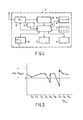
- Figure 5 is a graph illustrating the determination of the best time message signal to use as a reference, and
- Figure 6 is a flow chart illustrating measuring time in accordance with the present invention.
- In the drawings the same reference numerals have been used to illustrate corresponding features.
- The selective call system shown in Figure 1 comprises a paging network controller (PNC) 10 which is equipped with a
transmitter 12 and acontroller 14 which includes means for formatting signals to be transmitted, the signals may comprise pager identity codes (RICs) and/or message data such as date and time. A clock or othertime reference source 15 is connected to or forms a part of thePNC 10. - A plurality of paging receivers (or pagers) P1 to P4 are provided. The pagers are able to roam in and out of the coverage area of the
transmitter 12. Each pager P1 to P4 includes aradio receiver 16 tuned to the frequency of thetransmitter 12 and acontroller 18 which controls the energisation of theradio receiver 16, the date and time stamping of received alert and/or message signals and the energisation of an alerting device, for example an acoustic, visual and/or tactile transducer, in the event of the controller identifying the pager's RIC in a transmitted message. - The signal format is CCIR Radiopaging Code No. 1 or POGSAG and for the sake of completeness it will be described briefly with reference to Figure 2. However for fuller information reference may be made to "The book of the CCIR Radiopaging Code No. 1 " available from: Secretary RCSG, British Telecom, Radiopaging, 23 Howland Street, London W1 P 6HQ. The transmissions from the
PNC 10 comprises a series of bursts, each burst comprising a preamble 20 of 576 bits which serves to enable the pagers P1 to P4 achieve bit synchronisation, followed by concatenated batches of codewords formed by Radio Identity Codes (RICS) and data messages. Eachbatch synchronisation codeword 26 which is used by a pager to achieve/maintain word synchronisation. The remaining sixteen codewords are paired and each of the eight pairs is termed a frame, F1 to F8. Each pager is assigned to a particular frame which means that, if necessary its RIC, or more precisely any one of its RICs, will be transmitted in that frame, say frame F4, and no other. Thus as part of the inherent battery power conservation feature of POCSAG, the pager must energise itsradio receiver 16 firstly to be able to receive thesynchronisation codeword 26 and secondly for the duration of its frame, in this example F4, but for the duration of the other frames, that is F1 to F3 and F5 to F8, thereceiving section 16 can be de- energised. - Data messages comprise an address codeword plus one or more concatenated message codewords.
- With respect to the transmission of date and time messages, these may be sent at regular intervals, for example once in every N batches, where N has a value of two or more, for example N = 8, or once in every burst or less frequently, in order that battery power conservation may be practised in a predetermined manner. For the purposes of illustration the following description will assume that N = 8 batches.
- Referring to Figure 3, every N, where N = 8, batches form a superbatch SB and once in every superbatch date and time information in the form year, month, day, hour, minute, second and thousands of a second, such as 92/02/20 12 hours, 10 minutes, 21 seconds and 357/1000th of a second, is transmitted as 4 bit hexadecimal characters by the
PNC 10 in frames F1 and F2 ofbatch 0. More particularly the first codeword in the frame F1 includes function bits indicative of either that the following 3 codewords contain date and time information or not. A paging receiver or pager wishing to receive such a message signal is programmed to energise itsradio receiver 16 in order to not only receive the synchronisation word (or sync. word) but also to remain energised for frame F1 ofbatch 0 in order to be able to check that the first codeword contains function bits indicative of the fact that date and time information is to follow. In response to detecting this codeword, the pager remains energised for the remainder of the frame F1 and for the frame F2. Thereafter the pager is energised in the normal way to receive thesynchronisation codeword 26 in each batch and to be able to receive its RIC in its assigned frame. - Referring to Figure 4, the pager P comprises a housing, shown in broken lines, which contains a
radio receiver 16 and acontroller 18 with associated circuits and devices. Theradio receiver 16 can be of any suitable design, for example one based on Philips low power digital paging receiver IC type UAA 2033T or type UAA 2050T and thecontroller 18 may be based on the Philips DCA 5000T decoder. More particularly thecontroller 18 comprises adecoder 28 connected between an output of thereceiver 16 and an input to thecontroller 18. Thedecoder 28 accepts any signal received during the period(s) when the receiver is energised, error checks and corrects any errors possible within the capacity of the POCSAG code and presents the signals, codeword by codeword, to thecontroller 18 which as a first action checks whether the address codeword corresponds to one of the radiopager's RICs stored in the controller's non-volatile memory. If there is correspondence then in the case of an alert only paging signal, thecontroller 18 causes an audio, visual and/or tactilealerting device 30 to be energised. In the case of the received signal comprising concatenated message codewords then thecontroller 18 stores these together a date and time stamp in a RAM 32. In response to a command produced by the subscriber actuating a button on akeypad 34, thecontroller 18 causes the contents of the RAM 32 to be read out and supplied to thedriver 36 of anLCD panel 38. - In the event of there not being correspondence between the received address codeword(s) and the radiopager's RIC, the
controller 18 takes no action. - A
timing stage 40 is connected to thecontroller 18 and provides timing signals to thecontroller 18 so that it can carry out various operations including battery power conservation which is inherent in the POCSAG code. - The
timing stage 40 also includes areal time clock 42. On receipt of successive date and time messages, the controller stores the year, month and date in aRAM 44 together with time, after the time indicated in the time message signal has been adjusted to take into account the delays incurred in encoding and formatting the time message signal and propagation delays in transmitting signals to pagers P1 to P4 which may be roaming throughout the coverage area of the base station transmitter 12 (Figure 1). - Referring to Figure 1, a time signal Tc is generated by the
clock 15 and is supplied to thecontroller 14 which adapts the signal to a message format and stores it temporarily in readiness for transmission by thetransmitter 12 at the required moment, for example in frames F1 and F2 ofbatch 0 of the superbatch SB. The date and time signal is received by those pagers adapted to receive these signals. However the actual time of receipt will depend on the distance from the antenna of thePNC 10. Consequently there will be a variable delay between the origination of the time signal Tc and its actual time of receipt by a roaming pager. - The delay comprises two main elements, firstly the time delay within the
PNC 10 and secondly the propagation time to the respective pager. In accordance with the present invention a pager treats one of the received time message signals as a reference and its internal clock counts the time from that reference. However as the time message signal which is used as a reference may not be the optimum signal, the pager compares each newly received time message signal with the current reference and decides if the newly received time message signal is more accurate. - The processing of the time signal Tc in the
PNC 10 is assumed to involve a minimum time delay Tdm. Accordingly the accuracy of the time indicated in a time message signal Ts is improved if Tdm is added to Tc, thus -

- The propagation time to a pager plus the excess time over Tdm in
PNC 10 introduces a variable delay Tdv. In consequence the real time at the pager, Tr, of the receipt of the time message signal is:
- Substituting equation (1) into equation (2)

- If two signals Ts1, and Ts2 are in a sequence of time message signals then from equation (3)


- Subtracting equation (4) from equation (5), we get

- Examining equation (6), Ts1 and Ts2 are known, Tr1 and Tr2 are measured at the pager and Tdv1 and Tdv2 are unknown but can be calculated from equation (3), (4) or (5). However the smaller the value of Tdy, the closer Tr is to Ts and therefore the more accurate the value of Tr. Rewriting equation (6) we get
- Accordingly at switch-on of the pager, two successive times are noted and the computation shown in equation (7) is carried out in the controller 18 (Figure 4) and the right hand side of the equation is examined as to the sign of the difference and if it is positive then Ts1 is treated as the current reference signal, Tsref, and the real time clock 42 (Figure 4) counts from Tri. The opposite situation applies if the sign is negative and the
real time clock 42 counts from Tr2. - Thereafter on receipt of a subsequent time message signal Tsn, equation (7) is solved for
-

real time clock 42 is adjusted to treat Trn as zero and to start its count from there. This is illustrated in Figure 5 in which time message signals Ts5 and TS7 are assumed to become new reference signals. - In the event of the right hand side of equation (7) being zero, then the accuracy of Trn and Trref is the same and the pager can either change its reference signal or keep its existing reference signal.
- If the size of the difference in equation (7) is measured as well as determining the sign of the difference then the clock in the pager can be updated automatically for a change in time zones, which facility can be useful for automatically altering the time indicated on a watch or another device having a pager, such as a pocket sized personal computer having means for displaying time.
- Thus if a traveller disembarking at say an airport has a pager which is able to receive paging signals containing date and time message signals, then if when the newly received timing message signal is compared to the current reference signal, Tsref, the difference exceeds the time equivalent of
say 15 minutes, thecontroller 18 assumes that Tsref is grossly incorrect and assumes that the newly received signal is more correct and treats it as a new reference signal and simultaneously stores Tsn in the RAM 44 (Figure 4) and updates the indicated time to that contained in the time message signal. Thereafter the pager behaves as described previously. - The operation of selecting or verifying that Tsref is the best is described by equation (8). One method for implementing equation (8) is shown in Figure 6. The difference (Trn - Trref) is stored in a counter or store A. The time message signal Tsref is stored in a store B and the latest received time message signal Tsn is stored in a store C and finally Trn, which is the current time displayed, is stored in store D which has an input coupled to the
clock 42 and an output coupled to adisplay device 50. - From the items stored and the operations carried out in
blocks decision stage 56 is "Yes" (Y), that is A - (C -B) 0, then the operations inblocks - Alternatively if the output of the
decision stage 56 is "No" (N), then as a result of a new Tsret being selected store A is reset to zero and blocks 58,60 are enabled by the signal on the Y inputs so that the current value of Tsn is loaded into store B to become the new Tsref and into store D to indicate the current time on thedisplay device 50. - In a variant of the method in accordance with the present invention, the clock time Tc is transmitted as the time message signal without being altered by the addition of Tdm, as a result Tdy is greater due to having to take Tdm into account. Hence the value of TS,ef may be less accurate than the example described with reference to Figure 1. However for certain applications the reduced accuracy in TS,ef can be tolerated.
- If desired the correction value Tdm may be added to the indicated time on the pager when it has not been taken into account at the
PNC 10. - From reading the present disclosure, other modifications will be apparent to persons skilled in the art. Such modifications may involve other features which are already known in the design, manufacture and use of receiving systems for measuring time and component parts thereof and which may be used instead of or in addition to features already described herein. Although claims have been formulated in this application to particular combinations of features, it should be understood that the scope of the disclosure of the present application also includes any novel feature or any novel combination of features disclosed herein either explicitly or implicitly or any generalisation thereof, whether or not it relates to the same invention as presently claimed in any claim and whether or not it mitigates any or all of the same technical problems as does the present invention. The applicants hereby give notice that new claims may be formulated to such features and/or combinations of such features during the prosecution of the present application or of any further application derived therefrom.
Claims (10)
Applications Claiming Priority (2)
| Application Number | Priority Date | Filing Date | Title |
|---|---|---|---|
| GB9207861 | 1992-04-09 | ||
| GB929207861A GB9207861D0 (en) | 1992-04-09 | 1992-04-09 | A method of time measurement in a communications system,a communications system and a receiving apparatus for use in the system |
Publications (2)
| Publication Number | Publication Date |
|---|---|
| EP0565180A2 true EP0565180A2 (en) | 1993-10-13 |
| EP0565180A3 EP0565180A3 (en) | 1994-02-16 |
Family
ID=10713778
Family Applications (1)
| Application Number | Title | Priority Date | Filing Date |
|---|---|---|---|
| EP93200937A Withdrawn EP0565180A2 (en) | 1992-04-09 | 1993-04-01 | A method of time measurement in a communications system, a communications system and a receiving apparatus for use in the system |
Country Status (6)
| Country | Link |
|---|---|
| US (1) | US5363377A (en) |
| EP (1) | EP0565180A2 (en) |
| JP (1) | JPH0653888A (en) |
| KR (1) | KR930022739A (en) |
| GB (1) | GB9207861D0 (en) |
| SG (1) | SG44870A1 (en) |
Cited By (11)
| Publication number | Priority date | Publication date | Assignee | Title |
|---|---|---|---|---|
| GB2296166A (en) * | 1994-11-29 | 1996-06-19 | Plessey Telecomm | Telecommunications network clock adjustments |
| EP0720319A2 (en) * | 1994-12-30 | 1996-07-03 | AT&T Corp. | Clock recovery extrapolation |
| EP0726508A1 (en) * | 1995-02-07 | 1996-08-14 | Nokia Mobile Phones Ltd. | Real time clock suitable for a mobile telephone |
| WO1996027822A1 (en) * | 1995-03-03 | 1996-09-12 | Nexus 1994 Limited | Synchronization system for a shared channel communication system |
| WO1998014842A1 (en) * | 1996-10-03 | 1998-04-09 | H.P.M. Technologies Pty. Ltd. | Synchronization of a timepiece to a reference time |
| WO1998025158A1 (en) * | 1996-12-04 | 1998-06-11 | Snaptrack, Inc. | Method and apparatus for determining time for gps receivers |
| EP0849651A1 (en) * | 1996-12-18 | 1998-06-24 | Nec Corporation | Radio selective calling receiver |
| WO2000046646A1 (en) * | 1999-01-19 | 2000-08-10 | Lucent Technologies Inc. | Automatic clock setting |
| WO2000048367A2 (en) * | 1999-02-10 | 2000-08-17 | Nokia Wireless Routers, Inc. | Adaptive communication protocol for wireless networks |
| US6910147B2 (en) * | 2001-10-31 | 2005-06-21 | Intel Corporation | Digital recording apparatus real-time clock |
| US6928061B1 (en) | 2000-09-06 | 2005-08-09 | Nokia, Inc. | Transmission-scheduling coordination among collocated internet radios |
Families Citing this family (70)
| Publication number | Priority date | Publication date | Assignee | Title |
|---|---|---|---|---|
| ATE518388T1 (en) * | 1993-06-15 | 2011-08-15 | Celltrace Llc | TELECOMMUNICATIONS SYSTEM |
| JP3100826B2 (en) * | 1994-03-17 | 2000-10-23 | シャープ株式会社 | Pager with message display |
| EP0703514B1 (en) * | 1994-09-24 | 1998-07-22 | Eta SA Fabriques d'Ebauches | Time measurement in a communications system, a communications system and a receiver for use in such a system |
| US5590092A (en) * | 1995-01-05 | 1996-12-31 | Ericsson Inc. | Systems and methods for generating a current time of day in a cellular radiotelephone |
| EP0743800A3 (en) * | 1995-05-17 | 1999-01-27 | NEC Corporation | Paging system capable of calling pagers of different bit rates with efficient use of radio channels |
| US8606851B2 (en) | 1995-06-06 | 2013-12-10 | Wayport, Inc. | Method and apparatus for geographic-based communications service |
| US5835061A (en) | 1995-06-06 | 1998-11-10 | Wayport, Inc. | Method and apparatus for geographic-based communications service |
| US6282578B1 (en) | 1995-06-26 | 2001-08-28 | Hitachi, Ltd. | Execution management method of program on reception side of message in distributed processing system |
| US6940840B2 (en) | 1995-06-30 | 2005-09-06 | Interdigital Technology Corporation | Apparatus for adaptive reverse power control for spread-spectrum communications |
| US6697350B2 (en) | 1995-06-30 | 2004-02-24 | Interdigital Technology Corporation | Adaptive vector correlator for spread-spectrum communications |
| US7020111B2 (en) | 1996-06-27 | 2006-03-28 | Interdigital Technology Corporation | System for using rapid acquisition spreading codes for spread-spectrum communications |
| US6788662B2 (en) | 1995-06-30 | 2004-09-07 | Interdigital Technology Corporation | Method for adaptive reverse power control for spread-spectrum communications |
| US7072380B2 (en) | 1995-06-30 | 2006-07-04 | Interdigital Technology Corporation | Apparatus for initial power control for spread-spectrum communications |
| US7929498B2 (en) | 1995-06-30 | 2011-04-19 | Interdigital Technology Corporation | Adaptive forward power control and adaptive reverse power control for spread-spectrum communications |
| ZA965340B (en) | 1995-06-30 | 1997-01-27 | Interdigital Tech Corp | Code division multiple access (cdma) communication system |
| US5940382A (en) * | 1996-06-27 | 1999-08-17 | Interdigital Technology Corporation | Virtual locating of a fixed subscriber unit to reduce re-acquisition time |
| US6816473B2 (en) | 1995-06-30 | 2004-11-09 | Interdigital Technology Corporation | Method for adaptive forward power control for spread-spectrum communications |
| US6885652B1 (en) | 1995-06-30 | 2005-04-26 | Interdigital Technology Corporation | Code division multiple access (CDMA) communication system |
| US7123600B2 (en) | 1995-06-30 | 2006-10-17 | Interdigital Technology Corporation | Initial power control for spread-spectrum communications |
| US5594739A (en) * | 1995-11-01 | 1997-01-14 | Telefonaktiebolaget Lm Ericsson | System and method for rapid selection of synchronization sources in a mobile telecommunications network |
| JP3204614B2 (en) | 1996-06-21 | 2001-09-04 | 松下電器産業株式会社 | Wireless receiver |
| JPH1070747A (en) * | 1996-08-26 | 1998-03-10 | Kokusai Electric Co Ltd | Radio selective call receiver |
| US5859595A (en) * | 1996-10-31 | 1999-01-12 | Spectracom Corporation | System for providing paging receivers with accurate time of day information |
| US5966656A (en) * | 1997-03-11 | 1999-10-12 | Motorola, Inc. | Method and apparatus for displaying signal information in a radio communication device |
| JPH10311886A (en) * | 1997-05-13 | 1998-11-24 | Citizen Watch Co Ltd | Time information management system |
| JPH10341466A (en) * | 1997-06-10 | 1998-12-22 | Nec Shizuoka Ltd | Selective call radio receiver |
| US6230027B1 (en) * | 1997-06-17 | 2001-05-08 | U.S. Philips Corporation | Method of issuing a time information signal via a satellite station of a transmission system |
| US6078873A (en) * | 1997-10-02 | 2000-06-20 | Cummins Engine Company, Inc. | Method and apparatus for real-time data stamping via datalink and volatile ECM timer/clock |
| JP3811874B2 (en) * | 1997-10-28 | 2006-08-23 | 富士通株式会社 | Time correction method and mobile phone terminal device used in the method |
| US6223050B1 (en) * | 1997-12-09 | 2001-04-24 | Bellsouth Intellectual Property Management Corporation | System and method for automatically setting a remote timepiece with the correct time |
| KR100545805B1 (en) * | 1998-03-04 | 2006-04-14 | 엘지전자 주식회사 | How to display time during communication |
| JP2990156B1 (en) | 1998-06-10 | 1999-12-13 | 静岡日本電気株式会社 | Wireless communication device and wireless communication method |
| US7069055B1 (en) * | 1998-07-17 | 2006-06-27 | Samsung Electronics Co., Ltd. | Mobile telephone capable of displaying world time and method for controlling the same |
| DE69937682T2 (en) * | 1999-10-20 | 2008-11-20 | Sony Deutschland Gmbh | Mobile terminal for a wireless telecommunications method with accurate real-time generation |
| EP1226697B1 (en) | 1999-11-03 | 2010-09-22 | Wayport, Inc. | Distributed network communication system which enables multiple network providers to use a common distributed network infrastructure |
| US7546141B2 (en) * | 2000-05-23 | 2009-06-09 | Robert Leon | Hybrid communication system and method |
| US20020163422A1 (en) * | 2001-05-02 | 2002-11-07 | William Eggers | Service request communication system |
| US20050115478A1 (en) * | 2002-05-17 | 2005-06-02 | Pope G. M. | Mobile solid waste gasification unit |
| US7340264B2 (en) * | 2002-12-13 | 2008-03-04 | Research In Motion Limited | Methods and apparatus for providing consistency in SMS message timestamp formatting for mobile communication devices |
| US6826123B1 (en) * | 2003-10-14 | 2004-11-30 | International Business Machines Corporation | Global recovery for time of day synchronization |
| US7146160B1 (en) * | 2005-02-07 | 2006-12-05 | Uniden America Corporation | Caller identification logging system and method for use of same |
| KR100652018B1 (en) * | 2005-03-10 | 2006-12-01 | 주식회사 삼정파인스 | Pipe connecting device |
| CN100438618C (en) * | 2005-08-08 | 2008-11-26 | 乐金电子(中国)研究开发中心有限公司 | CI interface data transmission method based on time standard |
| KR100683379B1 (en) | 2005-09-12 | 2007-02-15 | 주식회사 케이티프리텔 | Method and device for providing current time information of mobilestation |
| US7617408B2 (en) | 2006-02-13 | 2009-11-10 | Schweitzer Engineering Labortories, Inc. | System and method for providing accurate time generation in a computing device of a power system |
| KR100761696B1 (en) * | 2006-06-13 | 2007-09-28 | 삼성전자주식회사 | Apparatus and method for transmission and reception of time information in mobile communication system |
| CN101897076B (en) | 2007-12-12 | 2014-03-19 | 日本电气株式会社 | Electrolytic corrosion prevention structure and waveguide connection structure |
| US8639267B2 (en) | 2008-03-14 | 2014-01-28 | William J. Johnson | System and method for location based exchanges of data facilitating distributed locational applications |
| US8761751B2 (en) | 2008-03-14 | 2014-06-24 | William J. Johnson | System and method for targeting data processing system(s) with data |
| US9078095B2 (en) | 2008-03-14 | 2015-07-07 | William J. Johnson | System and method for location based inventory management |
| US8600341B2 (en) | 2008-03-14 | 2013-12-03 | William J. Johnson | System and method for location based exchanges of data facilitating distributed locational applications |
| US8634796B2 (en) | 2008-03-14 | 2014-01-21 | William J. Johnson | System and method for location based exchanges of data facilitating distributed location applications |
| US8566839B2 (en) | 2008-03-14 | 2013-10-22 | William J. Johnson | System and method for automated content presentation objects |
| CA2757376A1 (en) * | 2009-04-03 | 2010-10-07 | Schweitzer Engineering Laboratories, Inc. | Fault tolerant time synchronization |
| US8867345B2 (en) * | 2009-09-18 | 2014-10-21 | Schweitzer Engineering Laboratories, Inc. | Intelligent electronic device with segregated real-time ethernet |
| US8351433B2 (en) * | 2009-09-18 | 2013-01-08 | Schweitzer Engineering Laboratories Inc | Intelligent electronic device with segregated real-time ethernet |
| US8812256B2 (en) | 2011-01-12 | 2014-08-19 | Schweitzer Engineering Laboratories, Inc. | System and apparatus for measuring the accuracy of a backup time source |
| WO2013133870A2 (en) | 2012-03-07 | 2013-09-12 | Snap Trends, Inc. | Methods and systems of aggregating information of social networks based on geographical locations via a network |
| CN103376738A (en) * | 2012-04-16 | 2013-10-30 | 鸿富锦精密工业(深圳)有限公司 | Electronic device, communication device, time calibration system and calibration method thereof |
| US9300591B2 (en) | 2013-01-28 | 2016-03-29 | Schweitzer Engineering Laboratories, Inc. | Network device |
| US9620955B2 (en) | 2013-03-15 | 2017-04-11 | Schweitzer Engineering Laboratories, Inc. | Systems and methods for communicating data state change information between devices in an electrical power system |
| US9270109B2 (en) | 2013-03-15 | 2016-02-23 | Schweitzer Engineering Laboratories, Inc. | Exchange of messages between devices in an electrical power system |
| US9065763B2 (en) | 2013-03-15 | 2015-06-23 | Schweitzer Engineering Laboratories, Inc. | Transmission of data over a low-bandwidth communication channel |
| US9477991B2 (en) | 2013-08-27 | 2016-10-25 | Snap Trends, Inc. | Methods and systems of aggregating information of geographic context regions of social networks based on geographical locations via a network |
| US9894489B2 (en) | 2013-09-30 | 2018-02-13 | William J. Johnson | System and method for situational proximity observation alerting privileged recipients |
| US9534486B2 (en) | 2014-03-13 | 2017-01-03 | Halliburton Energy Services Inc. | Method and system for tracking time in a downhole tool without the need for a battery |
| US9967135B2 (en) | 2016-03-29 | 2018-05-08 | Schweitzer Engineering Laboratories, Inc. | Communication link monitoring and failover |
| US10819727B2 (en) | 2018-10-15 | 2020-10-27 | Schweitzer Engineering Laboratories, Inc. | Detecting and deterring network attacks |
| US11522358B2 (en) | 2020-05-18 | 2022-12-06 | Schweitzer Engineering Laboratories, Inc. | Isolation of protective functions in electrical power systems |
| US11862958B2 (en) | 2021-10-04 | 2024-01-02 | Schweitzer Engineering Laboratories, Inc. | Isolation of protection functions in electrical power systems during startup |
Citations (2)
| Publication number | Priority date | Publication date | Assignee | Title |
|---|---|---|---|---|
| US4845491A (en) * | 1987-05-15 | 1989-07-04 | Newspager Corporation Of America | Pager based information system |
| WO1991016670A1 (en) * | 1990-04-18 | 1991-10-31 | At&E Corporation | Method and apparatus for accurate time maintenance and display |
Family Cites Families (5)
| Publication number | Priority date | Publication date | Assignee | Title |
|---|---|---|---|---|
| US4117661A (en) * | 1975-03-10 | 1978-10-03 | Bryant Jr Ellis H | Precision automatic local time decoding apparatus |
| US4337463A (en) * | 1980-08-22 | 1982-06-29 | Control Data Corporation | Time synchronization master station and remote station system |
| DE3244353A1 (en) * | 1982-12-01 | 1984-06-07 | Standard Elektrik Lorenz Ag, 7000 Stuttgart | DIGITAL RADIO TRANSMISSION SYSTEM |
| US5089814A (en) * | 1989-04-28 | 1992-02-18 | Motorola, Inc. | Automatic time zone adjustment of portable receiver |
| US5285496A (en) * | 1992-12-14 | 1994-02-08 | Firstperson, Inc. | Methods and apparatus for providing a secure paging system |
-
1992
- 1992-04-09 GB GB929207861A patent/GB9207861D0/en active Pending
-
1993
- 1993-04-01 EP EP93200937A patent/EP0565180A2/en not_active Withdrawn
- 1993-04-01 SG SG1996008935A patent/SG44870A1/en unknown
- 1993-04-07 JP JP5080641A patent/JPH0653888A/en active Pending
- 1993-04-08 KR KR1019930005856A patent/KR930022739A/en not_active Application Discontinuation
- 1993-04-09 US US08/045,834 patent/US5363377A/en not_active Expired - Fee Related
Patent Citations (2)
| Publication number | Priority date | Publication date | Assignee | Title |
|---|---|---|---|---|
| US4845491A (en) * | 1987-05-15 | 1989-07-04 | Newspager Corporation Of America | Pager based information system |
| WO1991016670A1 (en) * | 1990-04-18 | 1991-10-31 | At&E Corporation | Method and apparatus for accurate time maintenance and display |
Cited By (22)
| Publication number | Priority date | Publication date | Assignee | Title |
|---|---|---|---|---|
| US5712867A (en) * | 1992-10-15 | 1998-01-27 | Nexus 1994 Limited | Two-way paging apparatus having highly accurate frequency hopping synchronization |
| GB2296166B (en) * | 1994-11-29 | 1999-07-07 | Plessey Telecomm | Clock synchronisation |
| GB2296166A (en) * | 1994-11-29 | 1996-06-19 | Plessey Telecomm | Telecommunications network clock adjustments |
| EP0720319A2 (en) * | 1994-12-30 | 1996-07-03 | AT&T Corp. | Clock recovery extrapolation |
| EP0720319A3 (en) * | 1994-12-30 | 1999-05-06 | AT&T Corp. | Clock recovery extrapolation |
| EP0726508A1 (en) * | 1995-02-07 | 1996-08-14 | Nokia Mobile Phones Ltd. | Real time clock suitable for a mobile telephone |
| WO1996027822A1 (en) * | 1995-03-03 | 1996-09-12 | Nexus 1994 Limited | Synchronization system for a shared channel communication system |
| US6433734B1 (en) | 1996-03-08 | 2002-08-13 | Snaptrack, Inc. | Method and apparatus for determining time for GPS receivers |
| US5945944A (en) * | 1996-03-08 | 1999-08-31 | Snaptrack, Inc. | Method and apparatus for determining time for GPS receivers |
| WO1998014842A1 (en) * | 1996-10-03 | 1998-04-09 | H.P.M. Technologies Pty. Ltd. | Synchronization of a timepiece to a reference time |
| WO1998025158A1 (en) * | 1996-12-04 | 1998-06-11 | Snaptrack, Inc. | Method and apparatus for determining time for gps receivers |
| EP0849651A1 (en) * | 1996-12-18 | 1998-06-24 | Nec Corporation | Radio selective calling receiver |
| US6166651A (en) * | 1996-12-18 | 2000-12-26 | Nec Corporation | Radio selective calling receiver having automatic time correction function |
| CN1104147C (en) * | 1996-12-18 | 2003-03-26 | 日本电气株式会社 | Radio selective calling receiver with automatic time correction function |
| WO2000046646A1 (en) * | 1999-01-19 | 2000-08-10 | Lucent Technologies Inc. | Automatic clock setting |
| US6393306B1 (en) | 1999-01-19 | 2002-05-21 | Agere Systems Guardian Corp. | Automatic clock setting |
| WO2000048367A2 (en) * | 1999-02-10 | 2000-08-17 | Nokia Wireless Routers, Inc. | Adaptive communication protocol for wireless networks |
| WO2000048367A3 (en) * | 1999-02-10 | 2000-12-07 | Nokia Wireless Routers Inc | Adaptive communication protocol for wireless networks |
| US7184413B2 (en) | 1999-02-10 | 2007-02-27 | Nokia Inc. | Adaptive communication protocol for wireless networks |
| EP1845670A1 (en) * | 1999-02-10 | 2007-10-17 | Nokia Inc. | Adaptive communication protocol for wireless networks |
| US6928061B1 (en) | 2000-09-06 | 2005-08-09 | Nokia, Inc. | Transmission-scheduling coordination among collocated internet radios |
| US6910147B2 (en) * | 2001-10-31 | 2005-06-21 | Intel Corporation | Digital recording apparatus real-time clock |
Also Published As
| Publication number | Publication date |
|---|---|
| EP0565180A3 (en) | 1994-02-16 |
| US5363377A (en) | 1994-11-08 |
| KR930022739A (en) | 1993-11-24 |
| JPH0653888A (en) | 1994-02-25 |
| SG44870A1 (en) | 1997-12-19 |
| GB9207861D0 (en) | 1992-05-27 |
Similar Documents
| Publication | Publication Date | Title |
|---|---|---|
| EP0565180A2 (en) | A method of time measurement in a communications system, a communications system and a receiving apparatus for use in the system | |
| US5463382A (en) | Method and apparatus for controlling message transmissions in an acknowledge-back selective call communication system | |
| EP0703514B1 (en) | Time measurement in a communications system, a communications system and a receiver for use in such a system | |
| US5361397A (en) | Communication device and system capable of automatic programmable energizing | |
| EP0438463B1 (en) | High data rate simulcast communication system | |
| EP0511008B1 (en) | Wireless communication system | |
| US4403212A (en) | Digital radio paging communication system | |
| US4968966A (en) | High data rate simulcast communication system | |
| US4914649A (en) | Multiple frequency message system | |
| US5150954A (en) | Pager watch system utilizing time slot communication | |
| US5444438A (en) | Method and apparatus for remote memory management in an acknowledge-back selective call communication system | |
| KR960011189B1 (en) | Method and apparatus for maintaining synchronization in a simulcast system | |
| US5206855A (en) | Multiple frequency message system | |
| WO2000005833A2 (en) | Origination time and update lifetime with updatable messages | |
| CA2209519A1 (en) | Systems and methods for generating a current time of day in a cellular radiotelephone | |
| KR960012958B1 (en) | Paging receiver suitable for an emergency calll | |
| EP0765583B1 (en) | Selective call system | |
| EP0619685A2 (en) | Timepiece for radio display pager synchronised to the local standard time | |
| US5764632A (en) | Mobile terminal having improved paging channel acquisition in a system using a digital control channel | |
| US4720710A (en) | Paging receiver having a plurality of test modes | |
| EP0413963B1 (en) | Radio communication apparatus for rapidly knowing whether the apparatus is within or out of a service area | |
| JPH0588574B2 (en) | ||
| US5960326A (en) | Radio apparatus outputting an alarm prior to a scheduled time | |
| AU664647B2 (en) | Paging receiver capable of avoiding disturbance raised on reception of an unnecessary message | |
| WO1991011868A1 (en) | Paging system with time slot reassignment |
Legal Events
| Date | Code | Title | Description |
|---|---|---|---|
| PUAI | Public reference made under article 153(3) epc to a published international application that has entered the european phase |
Free format text: ORIGINAL CODE: 0009012 |
|
| AK | Designated contracting states |
Kind code of ref document: A2 Designated state(s): DE FR GB IT |
|
| PUAL | Search report despatched |
Free format text: ORIGINAL CODE: 0009013 |
|
| AK | Designated contracting states |
Kind code of ref document: A3 Designated state(s): DE FR GB IT |
|
| RAP1 | Party data changed (applicant data changed or rights of an application transferred) |
Owner name: N.V. PHILIPS' GLOEILAMPENFABRIEKEN Owner name: PHILIPS ELECTRONICS UK LIMITED |
|
| 17P | Request for examination filed |
Effective date: 19940728 |
|
| RAP3 | Party data changed (applicant data changed or rights of an application transferred) |
Owner name: KONINKLIJKE PHILIPS ELECTRONICS N.V. Owner name: PHILIPS ELECTRONICS UK LIMITED |
|
| STAA | Information on the status of an ep patent application or granted ep patent |
Free format text: STATUS: THE APPLICATION HAS BEEN WITHDRAWN |
|
| 18W | Application withdrawn |
Withdrawal date: 19990427 |