EP0478438B1 - Car navigation aid on-board receiver - Google Patents
Car navigation aid on-board receiver Download PDFInfo
- Publication number
- EP0478438B1 EP0478438B1 EP91402534A EP91402534A EP0478438B1 EP 0478438 B1 EP0478438 B1 EP 0478438B1 EP 91402534 A EP91402534 A EP 91402534A EP 91402534 A EP91402534 A EP 91402534A EP 0478438 B1 EP0478438 B1 EP 0478438B1
- Authority
- EP
- European Patent Office
- Prior art keywords
- receiver
- pixels
- messages
- section
- locations
- Prior art date
- Legal status (The legal status is an assumption and is not a legal conclusion. Google has not performed a legal analysis and makes no representation as to the accuracy of the status listed.)
- Expired - Lifetime
Links
Images

Classifications
-
- G—PHYSICS
- G01—MEASURING; TESTING
- G01C—MEASURING DISTANCES, LEVELS OR BEARINGS; SURVEYING; NAVIGATION; GYROSCOPIC INSTRUMENTS; PHOTOGRAMMETRY OR VIDEOGRAMMETRY
- G01C21/00—Navigation; Navigational instruments not provided for in groups G01C1/00 - G01C19/00
- G01C21/26—Navigation; Navigational instruments not provided for in groups G01C1/00 - G01C19/00 specially adapted for navigation in a road network
- G01C21/34—Route searching; Route guidance
- G01C21/36—Input/output arrangements for on-board computers
- G01C21/3691—Retrieval, searching and output of information related to real-time traffic, weather, or environmental conditions
- G01C21/3694—Output thereof on a road map
-
- G—PHYSICS
- G08—SIGNALLING
- G08G—TRAFFIC CONTROL SYSTEMS
- G08G1/00—Traffic control systems for road vehicles
- G08G1/09—Arrangements for giving variable traffic instructions
- G08G1/0962—Arrangements for giving variable traffic instructions having an indicator mounted inside the vehicle, e.g. giving voice messages
- G08G1/0968—Systems involving transmission of navigation instructions to the vehicle
- G08G1/0969—Systems involving transmission of navigation instructions to the vehicle having a display in the form of a map
Definitions
- the present invention relates to a vehicle navigation aid on-board receiver intended to receive, by transmitters and a specific broadcasting channel, coded messages containing at least problem locations of a finite sequence of locations stored in memory. the receiver and comprising means for decoding the messages and means for restoring them in a form accessible to a motorist.
- radio data system RDS Radio Data System
- TMC Traffic message channel
- the RDS system is based on a reference table, containing in particular numbers that are unequivocally associated with predetermined problem locations.
- the problem location table (PL table) is stored in the on-board receiver.
- Information on a problem can be associated with advice (turn away from X), information on weather conditions, etc.
- an RDS receiver receiving a coded problem message, decodes its cause, its effect as well as, using the stored table PL, the number or numbers of locations of the problem before, using a synthesizer, to restore the message in voice form (slowdown from A to B due to an accident, for example).
- the present invention relates to a vehicle navigation aid on-board receiver intended to receive, by transmitters and a specific broadcasting channel, coded messages containing at least problem locations of a finite sequence of locations stored in the receiver and comprising means for decoding messages and means for restoring them in a form accessible to a motorist, receiver characterized in that it includes a memory for storing pixels representative of road maps, means for displaying portions of these maps on display means and means for graphically restoring the location of messages problems on the display means, arranged for, when a traffic problem produces its effects on a section of road between two points, materializing this problem section on a portion of the displayed map by substituting, for the pixels of the section of the displayed portion of the map, pixels of a particular color.
- a card memorized in the form of a matrix or matrices of elementary image points, or pixels, for example a scanned card is distinguished from a vectorized card which, for its part, is memorized in the form of nodes and road axes.
- the receiver of the invention in its essential functions, is intended to be inserted in a system, not of navigation, but of aid to navigation, that is to say to receive messages on traffic conditions, leaving the motorist free to navigate, not on how to get from one point to another.
- the advantage of the receiver of the invention compared to that of the prior art with vocal restitution of messages, resides in the visualization in real time of the problems directly on real maps displayed.
- the graphical rendering of problem locations each being performed on few bits, approximately one byte, does not require a large capacity processing memory.
- the starting point of the invention is the RDS system, in which the display of maps, in any form whatsoever, was absolutely not intended.
- the display of maps was however known elsewhere.
- maps, synthetic and not real are displayed in the form of lines on which a motorist can materialize the position of his vehicle using a device magnetometric.
- the inventive step of the present invention therefore consisted of combining a navigation aid system of the RDS type with combining it with a variant of a navigation system, a priori incompatible with each other, in order to propose a system providing a result never achieved by either of the two systems of the prior art.
- said means for replacing the pixels of the receiver of the invention include means for recognizing contours to recognize those of said section of problem road.
- the display of the card portions takes place in color.
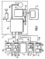
- the central unit 1 comprises a main processor 8, a graphics processor 9, a speech synthesis unit 10, connected to the processor 8, a mass memory 11 and a video memory 12, here a RAM, connected, to the main processor 8, by a bus 121.
- Each of the blocks 3, 4, 6 and 7 here comprises a microprocessor 31, 41, 61 and 71, respectively, whose memories, ROM and RAM, have not been shown for the sake of clarity. Nor have all the inter-processor link circuits been represented. It will also be noted that the functions of all or part of the microprocessors 31, 41, 61 and even of the blocks 3, 4, 6 could in fact be integrated with those of the main processor 8 of the central unit 1.
- the graphics terminal 2 connected to the graphics processor 9 by the video RAM 12 and controlled by circuits of the processor 9, constitutes the interface between the motorist and the receiver.
- it includes a high resolution color screen for displaying and viewing portions of road maps, control push buttons, for example to allow scrolling of maps, and adjustment potentiometers constituting designators connected to processor 9.
- the block 3 for processing broadcast messages here of the RDS type, comprises, connected to the microprocessor 31, a circuit 32 for receiving digital information transmitted by RDS transmitters and transmitted on the TMC channel, for decoding this information, sorting the relevant messages and sending these messages to the main processor 8 of the central unit 1 to which the microprocessor 31 is connected by a serial line 33.
- the RDS system is defined in a specification of the European Broadcasting Union, published in March 1984 and bearing the reference Tech. 3244-F.
- the block 4 for determining the heading of the vehicle comprises a magnetometer 42 connected to the microprocessor 41 for, from the measurement of the terrestrial magnetic field, deliver to the main processor 8 of the central unit 1, by a serial line 43, the heading followed by the vehicle.
- the block 5 for determining the distance traveled essentially comprises a counter controlled by an odometer and connected to the main processor 8.
- the block 6 for determining the position of the vehicle provides, in a known manner, an accuracy making it possible to follow the maps regardless of the duration of the trip or to permanently maintain the map presented on the screen centered on the position of the vehicle.
- the block 6 is inserted in a satellite system and comprises a reception circuit 62 connected to the microprocessor 61 also connected to the main processor 8 by a serial line 65.
- a reception circuit 62 connected to the microprocessor 61 also connected to the main processor 8 by a serial line 65.
- Block 7 completes the receiver of the invention in an attractive but not essential manner. It allows access to private and paid services using a memory card.
- Block 7 includes a bi-standard reader 72, for example of the type described in French patent application 2,638,876 in the name of the applicant, connected to microprocessor 71, itself connected to processor 8, and arranged to read indifferently CP8 type memory cards of low capacity and not writable or memory cards, of larger capacity, up to a few hundred thousand bytes (KB), and possibly writable.
- the services offered using block 7 can be diverse and varied, such as, for example, access to GPS correction information or to a radiotelephone system.
- a memory card intended to be used in connection with this block 7 can also serve as electronic anti-theft and even as a key for adjusting certain equipment of the vehicle.
- the memory card can also contain a database on a network of services useful for a road trip, such as the location, for example, of hotels, parking lots, petrol stations.
- the memory card can also be used as a recording medium for events occurring on board the vehicle to better manage and maintain it.
- the mass memory 11 contains all the databases useful for the operation of the receiver and in particular the cartographic databases (bit map) for the graphic terminus 2, more precisely pixels representative of road maps, for example scanned road maps.
- Mass memory can hold databases for an entire country. In this case, it has a very large capacity of several hundred KB (it can be for example a CD ROM memory) and it is materially independent from the central unit 1.
- the memory 11 can also, as in the case shown, contain only the databases relating to a region. It then has only an average capacity (it may be a hard disk) and it is integrated into the central unit 1. It is downloadable and connected to the processor 8 by a bus 111.
- the problem locations are stored in mass memory 11.
- the receiver In its function of displaying in real time traffic problems on the portions of cards displayed on the screen of terminal 2, the receiver operates in the following manner. A portion of the map being displayed on the screen, the center of which represents, as indicated above with respect to block 6, the position of the vehicle, arrives on block 3 a problem message, transmitted to processor 8. If the problem is not located on the portion of decay then displayed on the screen, nothing happens that the motorist can perceive. On the other hand, if the problem produces its effects in a place appearing on the screen, the processor 8 restores the problem on the screen and materializes it on the base map here using pointing icons. A sound reproduction by block 10 can be combined with graphic reproduction. Note that the receiver is capable of processing several messages simultaneously.
- the tracking of the maps can be automatic, thanks to the "GPS” or “differential GPS” function of block 6, it can also be carried out only semi-automatically, using the only dead reckoning of blocks 4, 5, or even purely manual, using the scrolling commands of the graphic terminal 2.
- the processor 8 for the visualization of this section, substitutes, for the pixels of the considered section of the portion of map displayed, pixels of a particular color, here black pixels. This substitution is carried out by recognizing the contours of the road section of the map according to a conventional method of contour recognition or that which will now be described with reference to FIG. 2.
- the receiver of the invention is inserted into a global system which makes it possible to increment, dynamically and in real time, on a background map, traffic problems by modifying the color of route plots, the system can be schematically defined by the chain of Figure 3.
- Means 150 of seizure (police, gendarmerie, municipalities, ...) transmit to a collection center 151 messages of problems. Thanks to a reference table 152, these messages are formatted and coded (153) before being transmitted by transmitters 154. These messages are received (155) by the receiver described above, which decodes them (156) and, thanks to the cartographic databases and to the problem locations stored in the mass memory 11, actually locates the problems (157) and, by recognizing contours (158) displays them dynamically on a screen of display terminal 2.
Abstract
Description
La présente invention concerne un récepteur de bord d'aide à la navigation automobile destiné à recevoir, par des émetteurs et un canal de radiodiffusion spécifique, des messages codés contenant au moins des localisations de problèmes d'une suite finie de localisations mise en mémoire dans le récepteur et comprenant des moyens de décodage des messages et des moyens de restitution de ceux-ci sous forme accessible à un automobiliste.The present invention relates to a vehicle navigation aid on-board receiver intended to receive, by transmitters and a specific broadcasting channel, coded messages containing at least problem locations of a finite sequence of locations stored in memory. the receiver and comprising means for decoding the messages and means for restoring them in a form accessible to a motorist.
On connait déjà, comme système d'aide à la navigation automobile, le système de données radio RDS (Radio Data System) qui, à partir d'émetteurs à modulation de fréquence et par un canal de messages de trafic TMC (Traffic message chanel), transmet à des véhicules équipés d'un récepteur RDS des informations numériques sur les conditions de circulation, la météorologie et d'autres services encore. Ce système est intéressant pour signaler les problèmes de circulation, essentiellement les bouchons, et, plus précisément, leurs localisations.We already know, as a car navigation aid system, the radio data system RDS (Radio Data System) which, from frequency modulation transmitters and through a traffic message channel TMC (Traffic message channel) , transmits digital information on traffic conditions, weather and other services to vehicles equipped with an RDS receiver. This system is useful for reporting traffic problems, mainly traffic jams, and, more precisely, their locations.
Le système RDS s'appuye sur une table de référence, contenant notamment des numéros associés de façon biunivoque à des localisations de problèmes prédéterminées. La table des localisations de problèmes (table PL) est mise en mémoire dans le récepteur de bord. Quand un problème surgit, qui peut être décelé par un système automatique, des services de police ou de gendarmerie, des services municipaux, par exemple, il est mis en forme, codé, puis transmis sous forme de trains d'octets par RDS sur le canal TMC.The RDS system is based on a reference table, containing in particular numbers that are unequivocally associated with predetermined problem locations. The problem location table (PL table) is stored in the on-board receiver. When a problem arises, which can be detected by an automatic system, police or gendarmerie services, municipal services, for example, it is formatted, coded, then transmitted in the form of byte trains by RDS on the TMC channel.
Un problème peut être défini, ou expliqué, par
- une cause (accident, par exemple),
- un effet ( bouchon, ralentissement ),
- un point A, si le problème est ponctuellement localisé, deux points A et B, si le problème produit son effet entre ces deux points (bouchon, ralentissement), une distance à partir d'un point A (ralentissement, bouchon, depuis ce point sur la distance considérée ), etc.
- a cause (accident, for example),
- an effect (traffic jam, slowing down),
- a point A, if the problem is punctually localized, two points A and B, if the problem produces its effect between these two points (traffic jam, deceleration), a distance from a point A (deceleration, traffic jam, from this point distance considered), etc.
A l'information sur un problème peuvent être associés un conseil (détournez vous sur X), des informations sur les conditions météorologiques, etc.Information on a problem can be associated with advice (turn away from X), information on weather conditions, etc.
Dans le système RDS, tel qu'il est actuellement mis en oeuvre, un récepteur RDS, recevant un message codé de problème, décode sa cause, son effet ainsi que, à l'aide de la table PL mémorisée, le ou les numéros de localisations du problème avant, par synthétiseur, de restituer le message sous forme vocale (ralentissement de A vers B pour cause d'accident, par exemple).In the RDS system, as it is currently implemented, an RDS receiver, receiving a coded problem message, decodes its cause, its effect as well as, using the stored table PL, the number or numbers of locations of the problem before, using a synthesizer, to restore the message in voice form (slowdown from A to B due to an accident, for example).
Il existe dans un pays comme la France environ 65 000 localisations de problèmes possibles. On conçoit aisément qu'une restitution sonore de qualité des messages RDS impliquerait donc une mémoire de synthétiseur d'une taille aujourd'hui parfaitement exclue.There are in a country like France about 65,000 locations of possible problems. It is easy to see that a sound reproduction of quality RDS messages would therefore imply a synthesizer memory of a size which is today perfectly excluded.
La demanderesse a cherché à résoudre ce problème sans pour autant d'ailleurs en limiter la solution à la spécification RDS.The Applicant has sought to resolve this problem without, however, limiting its solution to the RDS specification.
A cet effet, la présente invention concerne un récepteur de bord d'aide à la navigation automobile destiné à recevoir, par des émetteurs et un canal de radiodiffusion spécifique, des messages codés contenant au moins des localisations de problèmes d'une suite finie de localisations mise en mémoire dans le récepteur et comprenant des moyens de décodage de messages et des moyens de restitution de ceux-ci sous forme accessible à un automobiliste, récepteur caractérisé par le fait qu'il comporte une mémoire de stockage de pixels représentatifs de cartes routières, des moyens d'affichage de portions de ces cartes sur des moyens de visualisation et des moyens de restitution graphique des localisations de problèmes des messages sur les moyens de visualisation, agencés pour, quand un problème de circulation produit ses effets sur un tronçon de route entre deux points, matérialiser ce tronçon à problème sur une portion de carte affichée en substituant, aux pixels du tronçon de la portion de carte affichée, des pixels d'une couleur particulière.To this end, the present invention relates to a vehicle navigation aid on-board receiver intended to receive, by transmitters and a specific broadcasting channel, coded messages containing at least problem locations of a finite sequence of locations stored in the receiver and comprising means for decoding messages and means for restoring them in a form accessible to a motorist, receiver characterized in that it includes a memory for storing pixels representative of road maps, means for displaying portions of these maps on display means and means for graphically restoring the location of messages problems on the display means, arranged for, when a traffic problem produces its effects on a section of road between two points, materializing this problem section on a portion of the displayed map by substituting, for the pixels of the section of the displayed portion of the map, pixels of a particular color.
Il faut ici préciser qu'une carte mémorisée sous forme d'une matrice ou de matrices de points élémentaires d'image, ou pixels, par exemple une carte scannerisée, se distingue d'une carte vectorisée qui, elle, est mémorisée sous forme de noeuds et d'axes routiers.It should be specified here that a card memorized in the form of a matrix or matrices of elementary image points, or pixels, for example a scanned card, is distinguished from a vectorized card which, for its part, is memorized in the form of nodes and road axes.
Il faut encore préciser que le récepteur de l'invention, dans ses fonctions essentielles, est destiné à s'insérer dans un système, non pas de navigation, mais d'aide à la navigation, c'est-à-dire à recevoir des messages sur les conditions de circulation, en laissant l'automobiliste libre de son parcours, et non sur la manière de se rendre d'un point à un autre.It should also be specified that the receiver of the invention, in its essential functions, is intended to be inserted in a system, not of navigation, but of aid to navigation, that is to say to receive messages on traffic conditions, leaving the motorist free to navigate, not on how to get from one point to another.
L'avantage du récepteur de l'invention, comparé à celui de l'art antérieur à restitution vocale des messages, réside dans la visualisation en temps réel des problèmes directement sur des cartes réelles affichées. De plus, la restitution graphique des localisations de problèmes, chacune s'effectuant sur peu de bits, environ un octet, ne nécessite pas une mémoire de traitement de grande capacité.The advantage of the receiver of the invention, compared to that of the prior art with vocal restitution of messages, resides in the visualization in real time of the problems directly on real maps displayed. In addition, the graphical rendering of problem locations, each being performed on few bits, approximately one byte, does not require a large capacity processing memory.
Le point de départ de l'invention est le système RDS, dans lequel l'affichage de cartes, sous quelque forme que ce soit, n'était absolument pas prévu. L'affichage de cartes était pourtant connu par ailleurs. Dans le système de navigation dit de l'adaptation de carte (map matching), des cartes, synthétiques et non réelles, sont affichées sous forme de traits sur lesquels un automobiliste peut matérialiser la position de son véhicule à l'aide d'un dispositif magnétométrique.The starting point of the invention is the RDS system, in which the display of maps, in any form whatsoever, was absolutely not intended. The display of maps was however known elsewhere. In the navigation system called map matching, maps, synthetic and not real, are displayed in the form of lines on which a motorist can materialize the position of his vehicle using a device magnetometric.
L'activité inventive de la présente invention a donc consisté à partir d'un système d'aide à la navigation du type RDS à le combiner avec une variante d'un système de navigation, a priori incompatibles entre eux, pour proposer un système procurant un résultat jamais atteint par aucun des deux systèmes de l'art antérieur.The inventive step of the present invention therefore consisted of combining a navigation aid system of the RDS type with combining it with a variant of a navigation system, a priori incompatible with each other, in order to propose a system providing a result never achieved by either of the two systems of the prior art.
On notera que les documents US-A-4 409 583 et "Vehicle Navigation & Information Systems, Toronto, Ontario, 11-13, September 1989, pages 475-483, M. Tsuzawa et al. : advanced monile traffic information and communication system-AMTICS" enseignent bien des systèmes d'aide à la navigation mais qui ne permettent pas la visualisation dynamique en temps réel de problèmes de circulation sur des cartes réelles affichées. Les cartes concernées par ces systèmes de l'art antérieur n'y sont pas mémorisées sous forme de pixels.It should be noted that documents US-A-4 409 583 and "Vehicle Navigation & Information Systems, Toronto, Ontario, 11-13, September 1989, pages 475-483, M. Tsuzawa et al.: Advanced monile traffic information and communication system -AMTICS "teach many navigation aid systems but which do not allow dynamic visualization in real time of traffic problems on real displayed maps. The cards concerned by these systems of the prior art are not stored there in the form of pixels.
Avantageusement, lesdits moyens de substitution de pixels du récepteur de l'invention comportent des moyens de reconnaissance de contours pour reconnaitre ceux dudit tronçon de route à problème.Advantageously, said means for replacing the pixels of the receiver of the invention include means for recognizing contours to recognize those of said section of problem road.
Avantageusement encore, l'affichage des portions de cartes s'effectue en couleur.Advantageously also, the display of the card portions takes place in color.
L'invention sera mieux comprise à l'aide de la description suivante d'une forme de réalisation préférée du récepteur de l'invention, en référence au dessin annexé, sur lequel
- la figure 1 est une représentation schématique du récepteur;
- la figure 2 est une illustration de la reconnaissance des contours d'un tronçon de route mise en oeuvre dans le récepteur de la figure 1 et
- la figure 3 est une représentation schématique du système dans lequel s'insère le récepteur de la figure 1.
- Figure 1 is a schematic representation of the receiver;
- FIG. 2 is an illustration of the recognition of the contours of a section of road implemented in the receiver of FIG. 1 and
- FIG. 3 is a schematic representation of the system into which the receiver of FIG. 1 is inserted.
Le système, dans lequel s'insère le récepteur de l'invention et oui va maintenant être décrit en référence à la figure 1, est étendu, dans sa fonctionnalité, bien au-delà des seules caractéristiques revendiquées dans la présente demande. Il ne faut pas pour autant le considérer comme limitatif de l'invention.The system into which the receiver of the invention is inserted and yes will now be described with reference to FIG. 1, is extended, in its functionality, far beyond the only characteristics claimed in the present application. However, it should not be considered as limiting the invention.
Il ne s'agit que d'un système d'aide à la navigation automobile et non pas d'un système de guidage des automobilistes le long d'itinéraires.It is only a car navigation aid system and not a system for guiding motorists along routes.
Le récepteur, implanté à bord d'un véhicule, comporte
- une unité centrale 1,
- un terminal graphique de visualisation en couleur 2,
- un bloc 3 de traitement de messages radiodiffusés,
- un bloc 4 de détermination du cap du véhicule,
- un
bloc 5 de détermination de la distance parcourue, - un bloc 6 de détermination de la position du véhicule,
- un bloc 7 de services annexes.
- a central unit 1,
- a graphic display terminal in color 2,
- a block 3 for processing broadcast messages,
- a block 4 for determining the heading of the vehicle,
- a
block 5 for determining the distance traveled, - a block 6 for determining the position of the vehicle,
- a block 7 of ancillary services.
L'unité centrale 1 comporte un processeur principal 8, un processeur graphique 9, un bloc 10 de synthèse vocale, relié au processeur 8, une mémoire de masse 11 et une mémoire vidéo 12, ici une RAM, reliée, au processeur principal 8, par un bus 121. Chacun des blocs 3, 4, 6 et 7 comporte ici un microprocesseur 31, 41, 61 et 71, respectivement, dont les mémoires, ROM et RAM, n'ont pas été représentées par souci de clarté. N'ont pas non plus été représentés tous les circuits de liaison inter-processeurs. On notera d'ailleurs que les fonctions de tout ou partie des microprocesseurs 31, 41, 61 et même des blocs 3, 4, 6 pourraient en fait être intégrées à celles du processeur principal 8 de l'unité centrale 1.The central unit 1 comprises a main processor 8, a
Le terminal graphique 2, connecté au processeur graphique 9 par la RAM vidéo 12 et contrôlé par des circuits du processeur 9, constitue l'interface entre l'automobiliste et le récepteur. Il comporte ici un écran couleur à haute résolution d'affichage et de visualisation de portions de cartes routières, des boutons-poussoirs de commande, par exemple pour permettre le défilement de cartes, et des potentiomètres de réglage constituant des désignateurs reliés au processeur 9.The graphics terminal 2, connected to the
Le bloc 3 de traitement des messages radiodiffusés, ici de type RDS, comporte, relié au microprocesseur 31, un circuit 32 de réception des informations numériques émises par des émetteurs RDS et transmis sur le canal TMC, de décodage de ces informations, de tri des messages pertinents et d'envoi de ces messages au processeur principal 8 de l'unité centrale 1 auquel le microprocesseur 31 est relié par une ligne série 33. Le système RDS est défini dans une spécification de l'Union européenne de radiodiffusion, éditée en mars 1984 et portant la référence Tech. 3244-F.The block 3 for processing broadcast messages, here of the RDS type, comprises, connected to the
Le bloc 4 de détermination du cap du véhicule comporte un magnétomètre 42 relié au microprocesseur 41 pour, à partir de la mesure du champ magnétique terrestre, délivrer au processeur principal 8 de l'unité centrale 1, par une ligne série 43, le cap suivi par le véhicule.The block 4 for determining the heading of the vehicle comprises a
Le bloc 5 de détermination de la distance parcourue comporte essentiellement un compteur contrôlé par un odomètre et connecté au processeur principal 8.The
L'association de l'information de cap du bloc 4 et de l'information de distance parcourue du bloc 5, toujours dans le cadre de l'aide à la navigation et non d'un guidage, permet une navigation à l'estime destinée à assurer le suivi des portions de cartes routières affichées sur l'écran du terminal 2.The combination of the heading information of block 4 and the distance traveled information of
Une telle navigation à l'estime n'est pas suffisamment précise pour pouvoir suivre les cartes pendant plus de quelques dizaines de minutes. Pour éviter que l'automobiliste n'ait alors à recaler périodiquement la position de son véhicule en permanence, en replaçant lui-même à l'écran du terminal graphique 2 la portion de carte sur laquelle il se trouve, la fonction du bloc 6 peut être mise en oeuvre.Such dead reckoning is not precise enough to be able to follow the maps for more than a few tens of minutes. To prevent the motorist from having to periodically readjust the position of his vehicle permanently, by replacing the portion of the card on which he is on the screen of the graphic terminal 2, the function of block 6 can be implemented.
Le bloc 6 de détermination de la position du véhicule (global positionning system GPS ) assure, de façon connue, une précision permettant de suivre les cartes quelle que soit la durée du déplacement ou de maintenir en permanence la carte présentée à l'écran centrée sur la position du véhicule.The block 6 for determining the position of the vehicle (global positioning system GPS) provides, in a known manner, an accuracy making it possible to follow the maps regardless of the duration of the trip or to permanently maintain the map presented on the screen centered on the position of the vehicle.
Le bloc 6 s'insère dans un système de satellites et comporte un circuit de réception 62 relié au microprocesseur 61 aussi relié au processeur principal 8 par une ligne série 65. Pour améliorer encore la précision du bloc GPS 6, jusqu'à quelques mètres, on peut prévoir d'apporter une correction à son résultat. A partir de circuits récepteurs GPS standards fixes implantés au sol, en des points parfaitement connus, on détermine en temps réel les erreurs de position dues aux satellites du système qui sont transmises au circuit de réception mobile 62 pour corriger son résultat. Les informations de correction peuvent être transmises par le système, ici RDS, d'émission des messages radiodiffusés. Il ne s'agit pas d'un gros volume d'informations et le système RDS peut parfaitement l'absorber. Dans le cas d'un bloc de détermination de position ainsi perfectionné, ou bloc GPS différentiel, il est prévu un circuit de correction 63 et une liaison 64 entre les microprocesseurs des blocs 3 et 6.The block 6 is inserted in a satellite system and comprises a
Le bloc 7 complète le récepteur de l'invention de façon attractive mais non indispensable. Il permet l'accès à des services privés et payants à l'aide d'une carte à mémoire. Le bloc 7 comporte un lecteur bi-standard 72, par exemple du type décrit dans la demande de brevet français 2 638 876 au nom de la demanderesse, relié au microprocesseur 71, lui-même relié au processeur 8, et agencé pour lire indifféremment des cartes à mémoire de type CP8 de faible capacité et non inscriptible ou des cartes à mémoire, de plus grande capacité, allant jusqu'à quelques centaines de milliers de bytes (KB), et éventuellement inscriptibles.Block 7 completes the receiver of the invention in an attractive but not essential manner. It allows access to private and paid services using a memory card. Block 7 includes a
Les services offerts à l'aide du bloc 7 peuvent être divers et variés, comme par exemple l'accès aux informations de correction GPS ou à un système de radiotéléphone. Une carte à mémoire destinée à être utilisée en liaison avec ce bloc 7 peut aussi servir d'anti-vol électronique et même de clef de réglage de certains équipements du véhicule. La carte à mémoire peut également contenir une base de données sur un réseau de services utiles pour un voyage sur route, comme la localisation, par exemple, des hotels, des parkings, des stations-services. Enfin la carte à mémoire peut encore servir de support d'enregistrement d'évènements survenus à bord du véhicule pour mieux assurer sa gestion et sa maintenance.The services offered using block 7 can be diverse and varied, such as, for example, access to GPS correction information or to a radiotelephone system. A memory card intended to be used in connection with this block 7 can also serve as electronic anti-theft and even as a key for adjusting certain equipment of the vehicle. The memory card can also contain a database on a network of services useful for a road trip, such as the location, for example, of hotels, parking lots, petrol stations. Finally, the memory card can also be used as a recording medium for events occurring on board the vehicle to better manage and maintain it.
La mémoire de masse 11 contient toutes les bases de données utiles au fonctionnement du récepteur et notamment les bases de données cartographiques (bit map) pour le terminai graphique 2, plus précisément des pixels représentatifs de cartes routières, par exemple de cartes routières scannerisées.The
La mémoire de masse peut contenir les bases de données relatives à un pays entier. Dans ce cas, elle a une très grande capacité de plusieurs centaines de KB (il peut s'agir par exemple d'une mémoire CD ROM) et elle est matériellement indépendante de l'unité centrale 1.Mass memory can hold databases for an entire country. In this case, it has a very large capacity of several hundred KB (it can be for example a CD ROM memory) and it is materially independent from the central unit 1.
La mémoire 11 peut aussi, comme dans le cas représenté, ne contenir que les bases de données relatives à une région. Elle n'a alors qu'une capacité moyenne (il peut s'agir d'un disque dur) et elle est intégrée à l'unité centrale 1. Elle est téléchargeable et reliée au processeur 8 par un bus 111.The
Les localisations de problèmes sont stockées dans la mémoire de masse 11.The problem locations are stored in
Dans sa fonction d'affichage en temps réel des problèmes de circulation sur les portions de cartes affichées à l'écran du terminal 2, le récepteur fonctionne de la manière suivante. Une portion de carte étant affichée à l'écran, dont le centre représente, comme indiqué ci-dessus à propos du bloc 6, la position du véhicule, arrive sur le bloc 3 un message de problème, transmis au processeur 8. Si le problème n'est pas localisé sur la portion de carie alors affichée à l'écran, il ne se passe rien que l'automobiliste puisse percevoir. Par contre, si le problème produit ses effets en un endroit apparaissant à l'écran, le processeur 8 restitue le problème à l'écran et le matérialise sur le fond de carte ici à l'aide d'icones de pointage. Une restitution sonore par le bloc 10 peut être combinée à la restitution graphique. On notera que le récepteur est capable de traiter simultanément plusieurs messages.In its function of displaying in real time traffic problems on the portions of cards displayed on the screen of terminal 2, the receiver operates in the following manner. A portion of the map being displayed on the screen, the center of which represents, as indicated above with respect to block 6, the position of the vehicle, arrives on block 3 a problem message, transmitted to processor 8. If the problem is not located on the portion of decay then displayed on the screen, nothing happens that the motorist can perceive. On the other hand, if the problem produces its effects in a place appearing on the screen, the processor 8 restores the problem on the screen and materializes it on the base map here using pointing icons. A sound reproduction by block 10 can be combined with graphic reproduction. Note that the receiver is capable of processing several messages simultaneously.
On notera encore que, si le suivi des cartes peut être automatique, grâce à la fonction "GPS" ou "GPS différentiel" du bloc 6, il peut aussi ne s'effectuer que de manière semi-automatique, à l'aide de la seule navigation à l'estime des blocs 4, 5, ou même purement manuelle, à l'aide des commandes de défilement du terminal graphique 2.It will also be noted that, if the tracking of the maps can be automatic, thanks to the "GPS" or "differential GPS" function of block 6, it can also be carried out only semi-automatically, using the only dead reckoning of
Lorsque le problème produit ses effets sur un tronçon de route, entre deux points précis, le processeur 8, pour la visualisation de ce tronçon, substitue, aux pixels du tronçon considéré de la portion de carte affichée, des pixels d'une couleur particulière, ici des pixels noirs. Cette substitution s'effectue par reconnaissance des contours du tronçon de route de la carte suivant une méthode classique de reconnaissance de contours ou celle qui va maintenant être décrite en référence à la figure 2.When the problem produces its effects on a section of road, between two precise points, the processor 8, for the visualization of this section, substitutes, for the pixels of the considered section of the portion of map displayed, pixels of a particular color, here black pixels. This substitution is carried out by recognizing the contours of the road section of the map according to a conventional method of contour recognition or that which will now be described with reference to FIG. 2.
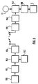
Soit une route R, d'une portion de carte, avec un problème de circulation entre les localisations A et B de cette route, l'utilisateur, en amont du point A, roulant dans le sens de la flèche F orientée de A vers B. Les coordonnées des points A et B sont parfaitement déterminées ainsi que la couleur de leurs pixels. On en déduit un pas d'exploration en X et un pas d'exploration en Y. A partir du point amont A, on explore, dans le premier quadrant, les pixels de la carte le long d'un vecteur AC parallèle à l'axe des Y et de longueur égale au pas en Y, puis d'un vecteur CD parallèle à l'axe des X et de longueur égale au pas en X, puis d'un vecteur DE, parallèle à l'axe des Y, de longueur égale au pas en Y et orienté en sens contraire de celui du vecteur AC.Either a route R, of a portion of the map, with a traffic problem between locations A and B of this route, the user, upstream of point A, driving in the direction of the arrow F oriented from A to B The coordinates of points A and B are perfectly determined as well as the color of their pixels. We deduce an exploration step in X and an exploration step in Y. From the upstream point A, we explore, in the first quadrant, the pixels of the map along an AC vector parallel to the axis of Y and of length equal to the step in Y, then of a vector CD parallel to the axis of X and of length equal to the step in X, then of a vector DE, parallel to the axis of Y, of length equal to the step in Y and oriented in the opposite direction to that of the vector AC.
Si au cours de l'exploration le long de ces trois vecteurs, on ne rencontre aucun pixel de la même couleur que ceux du point A, on recommence de façon similaire dans le deuxième quadrant et ainsi de suite.If during the exploration along these three vectors, we do not meet any pixel of the same color as those of point A, we start again in a similar way in the second quadrant and so on.
Si au cours de l'exploration, on rencontre une suite de pixels adjacents de la même couleur que ceux du point A et en nombre égal ou inférieur à ceux correspondant au point A, ou plus exactement à son épaisseur, c'est-à-dire l'épaisseur du tronçon de route sur la carte, on en déduit qu'il s'agit d'un point du tronçon de route ainsi intersecté, le joint F sur la figure 2, et on substitue aux pixels du segment de droite S entre la localisation de problème amont A et le premier point de route F ainsi reconnu, des pixels d'une couleur ici noire.If during exploration, we encounter a series of adjacent pixels of the same color as those of point A and in number equal to or less than those corresponding to point A, or more exactly its thickness, that is to say say the thickness of the road section on the map, we deduce that it is a point of the road section thus intersected, the joint F in FIG. 2, and we substitute for the pixels of the line segment S between the location of upstream problem A and the first waypoint F thus recognized, pixels of a color here black.
Puis on recommence le processus à partir du point F et ainsi de suite jusqu'à la localisation de problème aval B.Then we start the process again from point F and so on until the location of downstream problem B.
Si au cours de l'exploration, on rencontre une suite de pixels adjacents en nombre dépassant celui des pixels du point amont de départ et de la couleur de ceux-ci, ou plusieurs suites non adjacentes de pixels de la couleur de ceux du point de départ, on en déduit que, par exemple, des indications de marquage ont été explorées ou que des tronçons secondaires ont été intersectés et que les pas d'exploration retenus ne sont donc pas bons et on en change pour en adopter de plus petits.If during the exploration, we find a series of adjacent pixels in number exceeding that of the pixels of the upstream starting point and the color of these, or several non-adjacent series of pixels of the color of those of the point of At the outset, it is deduced therefrom that, for example, indications of marking have been explored or that secondary sections have been intersected and that the exploration steps retained are therefore not good and we change them to adopt smaller ones.
En définitive, le récepteur de l'invention est inséré dans un système global qui permet d'incruster, de façon dynamique et en temps réel, sur un fond de carte, des problèmes de circulation par modification de couleur de tracés de route, le système pouvant être schématiquement défini par la chaîne de la figure 3.Ultimately, the receiver of the invention is inserted into a global system which makes it possible to increment, dynamically and in real time, on a background map, traffic problems by modifying the color of route plots, the system can be schematically defined by the chain of Figure 3.
Des moyens 150 de saisie (police, gendarmerie, municipalités,... ) transmettent à un centre de recueil 151 des messages de problèmes. Grâce à une table de référence 152, ces messages sont mis en forme et codés (153) avant d'être émis par des émetteurs 154. Ces messages sont reçus (155) par le récepteur décrit ci-dessus, qui les décode (156) et, grâce aux bases de données cartographiques et aux localisations de problèmes stockées dans la mémoire de masse 11, localise réellement les problèmes (157) et, par reconnaissance de contours (158) les affiche en dynamique sur un écran de terminal de visualisation 2.
Claims (6)
- On-board receiver for assisting with motor vehicle navigation intended to receive, by transmitters (154) and a specific radio-broadcasting channel, coded messages containing at least locations of traffic problems from a finite sequence of locations stored in a memory (11) in the receiver and comprising means (32) for decoding messages and means (8-12, 2) for restoring the latter in a form accessible to a motorist, the receiver being characterised by the fact that it comprises a memory (11) for the storage of pixels representative of road-maps, means (8) for displaying portions of these maps on visualisation means (2) and means (8) for the graphic restoration of the locations of traffic problems coded by said messages on the visualisation means (2), arranged in order, when a traffic problem produces its effects on a section of road between two points (A, B), to materialise this section having a problem on a portion of map displayed by substituting, for the pixels of the section of the portion of map displayed, pixels of a particular colour.
- Receiver according to Claim 1, in which said means for the substitution of pixels comprise means (8) for the recognition of contours for recognising those of said section of road comprising a problem.
- Receiver according to one of Claims 1 and 2, in which a unit (3) is provided for processing radio-broadcast messages of the RDS type.
- Receiver according to one of Claims 1 to 3, in which a unit (4) is provided for determining the heading.
- Receiver according to one of Claims 1 to 4, in which a unit (5) is provided for determining the distance covered.
- Receiver according to one of Claims 1 to 5, in which a unit (6)is provided for determining the position.
Applications Claiming Priority (2)
| Application Number | Priority Date | Filing Date | Title |
|---|---|---|---|
| FR9011993A FR2667423B1 (en) | 1990-09-28 | 1990-09-28 | AUTOMOBILE NAVIGATION AID RECEIVER. |
| FR9011993 | 1990-09-28 |
Publications (2)
| Publication Number | Publication Date |
|---|---|
| EP0478438A1 EP0478438A1 (en) | 1992-04-01 |
| EP0478438B1 true EP0478438B1 (en) | 1995-12-13 |
Family
ID=9400758
Family Applications (1)
| Application Number | Title | Priority Date | Filing Date |
|---|---|---|---|
| EP91402534A Expired - Lifetime EP0478438B1 (en) | 1990-09-28 | 1991-09-24 | Car navigation aid on-board receiver |
Country Status (7)
| Country | Link |
|---|---|
| EP (1) | EP0478438B1 (en) |
| JP (1) | JPH04305684A (en) |
| AT (1) | ATE131650T1 (en) |
| CA (1) | CA2052370A1 (en) |
| DE (1) | DE69115417T2 (en) |
| ES (1) | ES2080924T3 (en) |
| FR (1) | FR2667423B1 (en) |
Cited By (6)
| Publication number | Priority date | Publication date | Assignee | Title |
|---|---|---|---|---|
| US6920392B2 (en) | 2001-04-27 | 2005-07-19 | Matsushita Electric Industrial Co., Ltd. | Digital map position transfer method |
| US6931319B2 (en) | 2000-12-08 | 2005-08-16 | Matsushita Electric Industrial Co., Ltd. | Method for transmitting information on position on digital map and device used for the same |
| US7353108B2 (en) | 2001-01-29 | 2008-04-01 | Matsushita Electric Industrial Co., Ltd. | Method and apparatus for transmitting position information on a digital map |
| US7634452B2 (en) | 1999-08-27 | 2009-12-15 | Panasonic Corporation | Method for locating road shapes using erroneous map data |
| US8219314B2 (en) | 1999-07-28 | 2012-07-10 | Panasonic Corporation | Method for transmitting location information on a digital map, apparatus for implementing the method and traffic information provision/reception system |
| US8554475B2 (en) | 2007-10-01 | 2013-10-08 | Mitac International Corporation | Static and dynamic contours |
Families Citing this family (10)
| Publication number | Priority date | Publication date | Assignee | Title |
|---|---|---|---|---|
| GB2271420A (en) * | 1992-10-07 | 1994-04-13 | Ford Motor Co | Vehicle navigation system |
| SE516278C2 (en) * | 1994-03-04 | 2001-12-10 | Volvo Ab | Traffic information systems and procedures for providing traffic information |
| US6111521A (en) * | 1996-09-18 | 2000-08-29 | Mannesmann Vdo Ag | Apparatus for supplying traffic-related information |
| DE19724556A1 (en) * | 1997-06-11 | 1998-12-17 | Opel Adam Ag | Unidirectional off-board navigation system |
| DE69817306T2 (en) | 1997-12-02 | 2004-06-24 | Siemens Ag | Device for processing a traffic announcement |
| KR100304831B1 (en) * | 1998-03-05 | 2001-11-22 | 김부성 | Traffic information receiving method and apparatus |
| US6873907B1 (en) | 1998-05-05 | 2005-03-29 | Magellan Dis, Inc. | Navigation system with user interface |
| ATE252721T1 (en) * | 1998-05-05 | 2003-11-15 | Magellan Dis Inc | NAVIGATION SYSTEM WITH USER INTERFACE |
| DE19822918A1 (en) * | 1998-05-22 | 1999-11-25 | Bosch Gmbh Robert | Device for graphically marking a street course with the aid of a location database |
| CN113483750A (en) * | 2021-07-06 | 2021-10-08 | 中铁十九局集团第五工程有限公司 | Data recorder with positioning function for development construction site inspection |
Family Cites Families (2)
| Publication number | Priority date | Publication date | Assignee | Title |
|---|---|---|---|---|
| US4409583A (en) * | 1981-02-23 | 1983-10-11 | Dahan Pierre Louis | Video system for assisting automobile traffic employing a segmented LCD display |
| WO1989006414A1 (en) * | 1987-12-28 | 1989-07-13 | Aisin Aw Co., Ltd. | Route search method for navigation system |
-
1990
- 1990-09-28 FR FR9011993A patent/FR2667423B1/en not_active Expired - Fee Related
-
1991
- 1991-09-24 AT AT91402534T patent/ATE131650T1/en not_active IP Right Cessation
- 1991-09-24 DE DE69115417T patent/DE69115417T2/en not_active Expired - Lifetime
- 1991-09-24 ES ES91402534T patent/ES2080924T3/en not_active Expired - Lifetime
- 1991-09-24 EP EP91402534A patent/EP0478438B1/en not_active Expired - Lifetime
- 1991-09-27 CA CA002052370A patent/CA2052370A1/en not_active Abandoned
- 1991-09-27 JP JP3249607A patent/JPH04305684A/en active Pending
Cited By (11)
| Publication number | Priority date | Publication date | Assignee | Title |
|---|---|---|---|---|
| US8219314B2 (en) | 1999-07-28 | 2012-07-10 | Panasonic Corporation | Method for transmitting location information on a digital map, apparatus for implementing the method and traffic information provision/reception system |
| US8838386B2 (en) | 1999-07-28 | 2014-09-16 | Panasonic Intellectual Property Corporation Of America | Method for transmitting location information on a digital map, apparatus for implementing the method, and traffic information provision/reception system |
| US7634452B2 (en) | 1999-08-27 | 2009-12-15 | Panasonic Corporation | Method for locating road shapes using erroneous map data |
| US8078563B2 (en) | 1999-08-27 | 2011-12-13 | Panasonic Corporation | Method for locating road shapes using erroneous map data |
| US6931319B2 (en) | 2000-12-08 | 2005-08-16 | Matsushita Electric Industrial Co., Ltd. | Method for transmitting information on position on digital map and device used for the same |
| US8655580B2 (en) | 2000-12-08 | 2014-02-18 | Panasonic Corporation | Method for transmitting information on position on digital map and device used for the same |
| US7353108B2 (en) | 2001-01-29 | 2008-04-01 | Matsushita Electric Industrial Co., Ltd. | Method and apparatus for transmitting position information on a digital map |
| US8185306B2 (en) | 2001-01-29 | 2012-05-22 | Panasonic Corporation | Method and apparatus for transmitting position information on a digital map |
| US6920392B2 (en) | 2001-04-27 | 2005-07-19 | Matsushita Electric Industrial Co., Ltd. | Digital map position transfer method |
| US9177487B2 (en) | 2001-04-27 | 2015-11-03 | Panasonic Intellectual Property Corporation Of America | Digital map position information transfer method |
| US8554475B2 (en) | 2007-10-01 | 2013-10-08 | Mitac International Corporation | Static and dynamic contours |
Also Published As
| Publication number | Publication date |
|---|---|
| ATE131650T1 (en) | 1995-12-15 |
| ES2080924T3 (en) | 1996-02-16 |
| JPH04305684A (en) | 1992-10-28 |
| EP0478438A1 (en) | 1992-04-01 |
| CA2052370A1 (en) | 1992-03-29 |
| FR2667423A1 (en) | 1992-04-03 |
| FR2667423B1 (en) | 1995-05-24 |
| DE69115417D1 (en) | 1996-01-25 |
| DE69115417T2 (en) | 1996-05-30 |
Similar Documents
| Publication | Publication Date | Title |
|---|---|---|
| EP0478438B1 (en) | Car navigation aid on-board receiver | |
| EP0974137B1 (en) | Interactive process for use as a navigational aid and device for its implementation | |
| CA2158500C (en) | Navigation system for an automotive vehicle | |
| EP1544574B1 (en) | Information distribution system and information distribution method | |
| DE10007348C2 (en) | navigation system | |
| KR20060062464A (en) | Point of interest service method for using digital multimedia broadcasting | |
| JPH0990869A (en) | Map associated information distribution system | |
| FR2801158A1 (en) | Mobile telephone map position display system includes electronic unit with position measurement providing map and direction locator allowing user map direction pointing | |
| US20040044470A1 (en) | Method for route guidance, and terminal equipment and central apparatus for use therein | |
| EP1862762A1 (en) | Position information identifier providing system, and position information identifier transmitting method and device | |
| JP4456667B2 (en) | Navigation device | |
| US6694253B2 (en) | Navigation device for receiving satellite broadcast distribution of map data | |
| EP1555512A1 (en) | Navigation apparatus | |
| US20090018763A1 (en) | Program recording device, program recording method, program recording program, and computer-readable recording medium | |
| JP5125676B2 (en) | Information distribution system, center device, questionnaire response acquisition method | |
| EP0595685A1 (en) | Method and device for vehicle guidance on roads | |
| US6594564B1 (en) | Data device for a motor vehicle | |
| JP2853775B2 (en) | Data broadcast receiver | |
| JP2005127756A (en) | Traffic information providing system and car navigation system | |
| JP2994961B2 (en) | Traffic information display device | |
| EP0925567B1 (en) | Method for locating an emergency call | |
| JP4403736B2 (en) | Navigation system and program | |
| JP3549082B2 (en) | Vehicle navigation system | |
| US7593970B2 (en) | Data receiving system, data broadcasting system, data receiving method and data broadcasting method | |
| FR2709545A1 (en) | Interactive navigational aid method, in particular for road navigation, and a device for its implementation |
Legal Events
| Date | Code | Title | Description |
|---|---|---|---|
| PUAI | Public reference made under article 153(3) epc to a published international application that has entered the european phase |
Free format text: ORIGINAL CODE: 0009012 |
|
| AK | Designated contracting states |
Kind code of ref document: A1 Designated state(s): AT BE CH DE ES FR GB IT LI LU NL SE |
|
| 17P | Request for examination filed |
Effective date: 19920928 |
|
| 17Q | First examination report despatched |
Effective date: 19950210 |
|
| GRAA | (expected) grant |
Free format text: ORIGINAL CODE: 0009210 |
|
| AK | Designated contracting states |
Kind code of ref document: B1 Designated state(s): AT BE CH DE ES FR GB IT LI LU NL SE |
|
| REF | Corresponds to: |
Ref document number: 131650 Country of ref document: AT Date of ref document: 19951215 Kind code of ref document: T |
|
| REF | Corresponds to: |
Ref document number: 69115417 Country of ref document: DE Date of ref document: 19960125 |
|
| REG | Reference to a national code |
Ref country code: ES Ref legal event code: FG2A Ref document number: 2080924 Country of ref document: ES Kind code of ref document: T3 |
|
| ITF | It: translation for a ep patent filed |
Owner name: JACOBACCI & PERANI S.P.A. |
|
| GBT | Gb: translation of ep patent filed (gb section 77(6)(a)/1977) |
Effective date: 19960307 |
|
| PLBE | No opposition filed within time limit |
Free format text: ORIGINAL CODE: 0009261 |
|
| STAA | Information on the status of an ep patent application or granted ep patent |
Free format text: STATUS: NO OPPOSITION FILED WITHIN TIME LIMIT |
|
| 26N | No opposition filed | ||
| REG | Reference to a national code |
Ref country code: GB Ref legal event code: IF02 |
|
| PGFP | Annual fee paid to national office [announced via postgrant information from national office to epo] |
Ref country code: LU Payment date: 20030814 Year of fee payment: 13 Ref country code: AT Payment date: 20030814 Year of fee payment: 13 |
|
| PGFP | Annual fee paid to national office [announced via postgrant information from national office to epo] |
Ref country code: SE Payment date: 20030815 Year of fee payment: 13 |
|
| PGFP | Annual fee paid to national office [announced via postgrant information from national office to epo] |
Ref country code: NL Payment date: 20030818 Year of fee payment: 13 |
|
| PGFP | Annual fee paid to national office [announced via postgrant information from national office to epo] |
Ref country code: DE Payment date: 20030908 Year of fee payment: 13 |
|
| PGFP | Annual fee paid to national office [announced via postgrant information from national office to epo] |
Ref country code: ES Payment date: 20030915 Year of fee payment: 13 |
|
| PGFP | Annual fee paid to national office [announced via postgrant information from national office to epo] |
Ref country code: GB Payment date: 20030916 Year of fee payment: 13 Ref country code: CH Payment date: 20030916 Year of fee payment: 13 |
|
| PGFP | Annual fee paid to national office [announced via postgrant information from national office to epo] |
Ref country code: FR Payment date: 20030930 Year of fee payment: 13 |
|
| PGFP | Annual fee paid to national office [announced via postgrant information from national office to epo] |
Ref country code: BE Payment date: 20031010 Year of fee payment: 13 |
|
| PG25 | Lapsed in a contracting state [announced via postgrant information from national office to epo] |
Ref country code: DE Free format text: LAPSE BECAUSE OF THE APPLICANT RENOUNCES Effective date: 20040504 |
|
| PG25 | Lapsed in a contracting state [announced via postgrant information from national office to epo] |
Ref country code: LU Free format text: LAPSE BECAUSE OF NON-PAYMENT OF DUE FEES Effective date: 20040924 Ref country code: GB Free format text: LAPSE BECAUSE OF NON-PAYMENT OF DUE FEES Effective date: 20040924 Ref country code: AT Free format text: LAPSE BECAUSE OF NON-PAYMENT OF DUE FEES Effective date: 20040924 |
|
| PG25 | Lapsed in a contracting state [announced via postgrant information from national office to epo] |
Ref country code: SE Free format text: LAPSE BECAUSE OF NON-PAYMENT OF DUE FEES Effective date: 20040925 Ref country code: ES Free format text: LAPSE BECAUSE OF NON-PAYMENT OF DUE FEES Effective date: 20040925 |
|
| PG25 | Lapsed in a contracting state [announced via postgrant information from national office to epo] |
Ref country code: LI Free format text: LAPSE BECAUSE OF NON-PAYMENT OF DUE FEES Effective date: 20040930 Ref country code: CH Free format text: LAPSE BECAUSE OF NON-PAYMENT OF DUE FEES Effective date: 20040930 Ref country code: BE Free format text: LAPSE BECAUSE OF NON-PAYMENT OF DUE FEES Effective date: 20040930 |
|
| BERE | Be: lapsed |
Owner name: SOC. D'APPLICATIONS GENERALES D'ELECTRICITE ET DE Effective date: 20040930 |
|
| PG25 | Lapsed in a contracting state [announced via postgrant information from national office to epo] |
Ref country code: NL Free format text: LAPSE BECAUSE OF NON-PAYMENT OF DUE FEES Effective date: 20050401 |
|
| EUG | Se: european patent has lapsed | ||
| GBPC | Gb: european patent ceased through non-payment of renewal fee |
Effective date: 20040924 |
|
| REG | Reference to a national code |
Ref country code: CH Ref legal event code: PL |
|
| PG25 | Lapsed in a contracting state [announced via postgrant information from national office to epo] |
Ref country code: FR Free format text: LAPSE BECAUSE OF NON-PAYMENT OF DUE FEES Effective date: 20050531 |
|
| NLV4 | Nl: lapsed or anulled due to non-payment of the annual fee |
Effective date: 20050401 |
|
| REG | Reference to a national code |
Ref country code: FR Ref legal event code: ST |
|
| PG25 | Lapsed in a contracting state [announced via postgrant information from national office to epo] |
Ref country code: IT Free format text: LAPSE BECAUSE OF NON-PAYMENT OF DUE FEES;WARNING: LAPSES OF ITALIAN PATENTS WITH EFFECTIVE DATE BEFORE 2007 MAY HAVE OCCURRED AT ANY TIME BEFORE 2007. THE CORRECT EFFECTIVE DATE MAY BE DIFFERENT FROM THE ONE RECORDED. Effective date: 20050924 |
|
| REG | Reference to a national code |
Ref country code: ES Ref legal event code: FD2A Effective date: 20040925 |
|
| BERE | Be: lapsed |
Owner name: SOC. D'APPLICATIONS GENERALES D'ELECTRICITE ET DE Effective date: 20040930 |