EP0346461B1 - Systeme pour appareils de transports aeriens permettant d'ameliorer la precision d'un systeme de localisation des appareils - Google Patents
Systeme pour appareils de transports aeriens permettant d'ameliorer la precision d'un systeme de localisation des appareils Download PDFInfo
- Publication number
- EP0346461B1 EP0346461B1 EP89902357A EP89902357A EP0346461B1 EP 0346461 B1 EP0346461 B1 EP 0346461B1 EP 89902357 A EP89902357 A EP 89902357A EP 89902357 A EP89902357 A EP 89902357A EP 0346461 B1 EP0346461 B1 EP 0346461B1
- Authority
- EP
- European Patent Office
- Prior art keywords
- satellite
- ground
- vehicle
- signal
- stations
- Prior art date
- Legal status (The legal status is an assumption and is not a legal conclusion. Google has not performed a legal analysis and makes no representation as to the accuracy of the status listed.)
- Expired - Lifetime
Links
Images


Classifications
-
- G—PHYSICS
- G01—MEASURING; TESTING
- G01S—RADIO DIRECTION-FINDING; RADIO NAVIGATION; DETERMINING DISTANCE OR VELOCITY BY USE OF RADIO WAVES; LOCATING OR PRESENCE-DETECTING BY USE OF THE REFLECTION OR RERADIATION OF RADIO WAVES; ANALOGOUS ARRANGEMENTS USING OTHER WAVES
- G01S5/00—Position-fixing by co-ordinating two or more direction or position line determinations; Position-fixing by co-ordinating two or more distance determinations
- G01S5/0009—Transmission of position information to remote stations
-
- G—PHYSICS
- G01—MEASURING; TESTING
- G01S—RADIO DIRECTION-FINDING; RADIO NAVIGATION; DETERMINING DISTANCE OR VELOCITY BY USE OF RADIO WAVES; LOCATING OR PRESENCE-DETECTING BY USE OF THE REFLECTION OR RERADIATION OF RADIO WAVES; ANALOGOUS ARRANGEMENTS USING OTHER WAVES
- G01S19/00—Satellite radio beacon positioning systems; Determining position, velocity or attitude using signals transmitted by such systems
- G01S19/01—Satellite radio beacon positioning systems transmitting time-stamped messages, e.g. GPS [Global Positioning System], GLONASS [Global Orbiting Navigation Satellite System] or GALILEO
- G01S19/13—Receivers
- G01S19/24—Acquisition or tracking or demodulation of signals transmitted by the system
- G01S19/30—Acquisition or tracking or demodulation of signals transmitted by the system code related
-
- G—PHYSICS
- G01—MEASURING; TESTING
- G01S—RADIO DIRECTION-FINDING; RADIO NAVIGATION; DETERMINING DISTANCE OR VELOCITY BY USE OF RADIO WAVES; LOCATING OR PRESENCE-DETECTING BY USE OF THE REFLECTION OR RERADIATION OF RADIO WAVES; ANALOGOUS ARRANGEMENTS USING OTHER WAVES
- G01S19/00—Satellite radio beacon positioning systems; Determining position, velocity or attitude using signals transmitted by such systems
- G01S19/38—Determining a navigation solution using signals transmitted by a satellite radio beacon positioning system
-
- G—PHYSICS
- G01—MEASURING; TESTING
- G01S—RADIO DIRECTION-FINDING; RADIO NAVIGATION; DETERMINING DISTANCE OR VELOCITY BY USE OF RADIO WAVES; LOCATING OR PRESENCE-DETECTING BY USE OF THE REFLECTION OR RERADIATION OF RADIO WAVES; ANALOGOUS ARRANGEMENTS USING OTHER WAVES
- G01S5/00—Position-fixing by co-ordinating two or more direction or position line determinations; Position-fixing by co-ordinating two or more distance determinations
- G01S5/02—Position-fixing by co-ordinating two or more direction or position line determinations; Position-fixing by co-ordinating two or more distance determinations using radio waves
- G01S5/0205—Details
- G01S5/021—Calibration, monitoring or correction
-
- G—PHYSICS
- G01—MEASURING; TESTING
- G01S—RADIO DIRECTION-FINDING; RADIO NAVIGATION; DETERMINING DISTANCE OR VELOCITY BY USE OF RADIO WAVES; LOCATING OR PRESENCE-DETECTING BY USE OF THE REFLECTION OR RERADIATION OF RADIO WAVES; ANALOGOUS ARRANGEMENTS USING OTHER WAVES
- G01S5/00—Position-fixing by co-ordinating two or more direction or position line determinations; Position-fixing by co-ordinating two or more distance determinations
- G01S5/02—Position-fixing by co-ordinating two or more direction or position line determinations; Position-fixing by co-ordinating two or more distance determinations using radio waves
- G01S5/0205—Details
- G01S5/0221—Receivers
-
- G—PHYSICS
- G01—MEASURING; TESTING
- G01S—RADIO DIRECTION-FINDING; RADIO NAVIGATION; DETERMINING DISTANCE OR VELOCITY BY USE OF RADIO WAVES; LOCATING OR PRESENCE-DETECTING BY USE OF THE REFLECTION OR RERADIATION OF RADIO WAVES; ANALOGOUS ARRANGEMENTS USING OTHER WAVES
- G01S5/00—Position-fixing by co-ordinating two or more direction or position line determinations; Position-fixing by co-ordinating two or more distance determinations
- G01S5/02—Position-fixing by co-ordinating two or more direction or position line determinations; Position-fixing by co-ordinating two or more distance determinations using radio waves
- G01S5/06—Position of source determined by co-ordinating a plurality of position lines defined by path-difference measurements
Definitions
- This invention relates to vehicle locating systems and more specifically to vehicle locating systems useful in an air traffic control environment which is based upon the use of satellite and ground station components to provide location accuracies superior to those based entirely upon either satellite or ground station components alone.
- the air traffic control system in the United States has as its primary performance criterion the safety of air traffic. Under such circumstances and criterion, uncertainty of the location of aircraft directly translates into large separation requirements between aircraft. Furthermore, present systems which are primarily radar based require the use of transponders aboard the aircraft which must be set by the pilot to a predetermined code in order to identify the aircraft. If the aircraft is equipped with a mode C transponder, altitude may be transmitted on the transponder's signal to an interrogating radar, but such an altitude signal is dependent upon the availability on the aircraft of an altitude encoder in addition to the radar transponder.
- Radar coverage does not exist throughout the United States but is generally concentrated in areas of high population or frequent on-route flights. As a result, the air traffic control system is severely limited in it's capacity in areas where radar coverage is not available and only the pilot's reporting of position may be relied upon to locate the aircraft. As a result, large separations between aircraft must be provided.
- location of aircraft is provided to a human air traffic controller who provides separation and conflict alerting on the basis of the enhanced radar display before him. While certain computerized conflict alert systems are available, such systems are not very useful in highly congested areas, since the location accuracies of the radar system and the performance envelopes of the aircraft cause many false alarms. Thus, poor location accuracy reduces the air traffic system capacity and the ability to perform computed conflict alert in congested air space.
- Satellite based vehicle location systems such as the Geostar System described in U.S. Patent 4,359,733, dated Nov. 16, 1982 have been proposed to address the accuracy and capacity problems of the existing air traffic control system and to automate the reporting of potential conflicts to pilots based upon information derived from computer determination of aircraft location for aircraft equipped with the appropriate electronic equipment.
- such systems have generally required relatively expensive airborne equipment and complex and expensive satellite systems in order to provide the services required.
- GDOP Geometric Dilution of Precision
- GDOP factors greater than 100 are typical.
- a system constructed with ground based repeaters would suffer from a similar GDOP problem in the elevation plane, since the crossing angles of the lines of position for such a system are also small. These magnitudes of GDOP require larger than desired spacing between aircraft.
- the present invention provides improvements to a satellite based vehicle location system (VLS) such as the system described in EP-A-279834.
- VLS satellite based vehicle location system
- the basic VLS system according to the invention relies upon at least one simple transponder satellite that receives encoded messages from a transmitter located on an airborne vehicle and retransmits them to a common base station.
- the position of the airborne user is derived from the time difference of arrival (TDOA) of the signals relayed by the satellites.
- TDOA time difference of arrival
- the vehicle location system according to the present invention is defined in claim 1.
- the present invention involves the use of strategically based ground enhancement stations that precisely delay retransmission of a signal received from an airborne vehicle.
- the ground enhancement stations retransmit the signal to the satellite (with an added data signal to identify the particular ground enhancement station that is transmitting).
- the satellite acting as a "bent pipe" transponder, retransmit this information to the common ground base stations that incorporate the ability to calculate the position of the airborne vehicle on the basis of the known geometry of the satellite and ground enhancement stations and the TDOA (time difference of arrival) of the received signals.
- the hybrid system according to the present invention preferably employs aircraft signal reception and retransmission at at least one ground enhancement station and three satellites to provide greatly reduced GDOP compared to systems consisting only of repeaters located at a satellite or satellites. Furthermore, if the aircraft is in range of at least two ground enhancement stations, a further reduction of the GDOP factor is attained compared with the case when the user aircraft is in range of only one ground enhancement station.
- the highest accuracies (and lowest GDOP) occur in an overdetermined (i.e. redundant navigational data) system with approximately seven ground stations surrounding a Terminal Control Area (TCA) of an airport.
- TCA Terminal Control Area
- the common base station computer can then select the set of signals that produce optimum geometry for lowest GDOP.
- the present invention preferably utilizes a simple and inexpensive transmitter aboard each aircraft that is designed to incorporate a code unique to that vehicle.
- the transmitter is designed to be operational the entire time that the aircraft is being operated, including when it is being taxied on the taxiways at the airport; however, during taxi operations, the duty cycle is selected to be relatively long in a preferred embodiment.
- All signals are preferably short duration pulses employing spread spectrum pseudonoise modulation for the purpose of achieving high range resolution and good discrimination between overlapping signals from multiple aircraft.
- This waveform design is totally compatible with that employed in the aforementioned EP-A-279834.
- the transmitter described above provides means of uniquely identifying each aircraft while it is being operated, but the simplicity of the transmitter prevents unnecessary costs for aircraft operating within the system.
- the aircraft may also be equipped with a conflict alert receiver which is capable of receiving a message designed to alert the pilot that a potential collision is developing between his aircraft and that of another.
- a conflict alert system could also incorporate means to provide the pilot with a suggested course of action to avoid the conflict.
- Such a conflict avoidance message would be based upon the calculation of the position and projected position of all aircraft in the system and various collision avoidance criteria programmed into a central computer in the base station.
- the signal transmitted by the airborne user is received by one or more satellites and a plurality of ground stations within the line of sight and range of the transmitter.
- the frequency of the transmitter should be chosen to provide for reliable line of sight communication between the airborne vehicle and the satellite and ground stations.
- the satellite portion of the system preferably incorporates relatively simple satellites, preferably located at synchronous altitudes, which provide a "bent pipe" transponder system to relay the signal received from the airborne vehicle to a remote ground base station without processing the signal in any way.
- the satellites may be tracked and their precise location determined by separate means, such as dedicated tracking stations or a satellite tracking network.
- the satellite preferably retransmits the signals received from the airborne vehicle on a narrow beam to an antenna located at the ground base station.
- the ground base station may incorporate a plurality of narrow beam receiving antennas, each of which is pointed at its respective satellite, so that the satellites may all operate at a similar frequency without interfering with one another.
- different frequencies may be assigned to each satellite and their signals separated upon receipt by a single wide beam antenna.
- a plurality of ground enhancement stations are located, e.g. throughout the United States, to provide coverage of airborne vehicles and to receive the transmissions of the airborne vehicle transmitters.
- Each ground enhancement station then retransmits the signals received from the airborne vehicles, preferably on a new frequency (to allow simultaneous transmissions and receptions from more than one aircraft) and superimposing upon the signal the ground station identification.
- the time of retransmission is precisely controlled so that the integrity of the measurement system is preserved.
- the ground base station then calculates the position of the airborne user based upon the known locations of the satellites and the various ground enhancement stations and the time difference of arrival (TDOA) of the signals transmitted directly from the airborne user to the satellite and the relayed signals through the ground enhancement stations.
- TDOA time difference of arrival
- the location accuracy of a vehicle location system is substantially enhanced in that the Geometric Dilution of Precision (GDOP) associated with either all satellite or all ground based schemes is substantially reduced.
- GDOP Geometric Dilution of Precision
- This reduction in GDOP is possible because the crossing angles of the hyperbola of constant time delay for ground stations and the hyperbola of constant time delay for satellites is substantially greater than the crossing angle from satellite to satellite or ground station to ground station for most available geometries.
- the errors associated with accuracy of time delay measurement are greatly reduced, since such errors are manifest in increased radii of the hyperbola generated.
- the hyperbola meet at shallow angles, the area of uncertainty is much larger than when they meet at relatively steep angles and the area of uncertainty is minimized when the crossing angles approach 90°.
- the present invention provides these improved accuracies while minimizing the expense of the airborne, spaceborne and land based elements of the system, since none of these components require complex electronics or computing capability except for a small number of central processing base stations designed to derive position and determine potential conflicts.
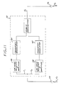
- FIG. 1 is a schematic overview of an arrangement of the components and the airborne user in an embodiment of the present invention.
- FIG. 2 is an illustration of the tetrahedron formed by the unit vectors from the user to the satellites of a vehicle location system.
- FIG. 3 is a schematic illustration of the components of an embodiment of the present invention illustrating a single user ground enhancement station, satellite repeater and ground base station for the purposes of simplicity.
- FIG. 4 is a graphic representation of enhancement station locations and coverage versus user typical altitude.
- FIG. 5 is an exemplary distribution of a ground enhancement station deployment for the Southern California area illustrating ground enhancement stations placed at the higher elevations in the area.
- FIG. 6 is a graph of Geometric Dilution of Precision (GDOP) at a latitude of 33 40′ as a function of longitude for the eight (8) ground enhancement stations of FIG. 4, illustrating the improvement in GDOP with the addition of one satellite to the basic ground enhancement station GDOP capability.
- GDOP Geometric Dilution of Precision
- FIG. 7 is a graph of the number of sites required in one embodiment for a nationwide deployment of ground enhancement stations for the present invention as a function of aircraft altidude coverage for ground enhancement station heights above terrain of 0 feet, and 1,000 feet.
- FIG. 8 is a representation of the geometric relationships associated with the derivation of the number of sites for a continental United States deployment in another embodiment of the present invention.
- FIG. 9 is a schematic illustration of the arrangement of components of a ground enhancement station in accordance with the present invention.
- FIG. 10 is a schematic illustration of the arrangement of the components of the electronic transmitter system for an airborne user of an embodiment in accordance with the present invention.
- FIG. 11 illustrates the arrangement of the components in the satellite portion of an embodiment in accordance with the present invention.
- FIG. 12 illustrates the arrangement of the components of the ground base station of an embodiment in accordance with the present invention.
- the invention is embodied in a vehicle locating system that uses both satellite based and ground based transponders to relay signals from an airborne user's transmitter to a ground base station at which the calculation of the position of the airborne user is made, based upon the known geometry and locations of the satellites and ground base stations and the time differences between the receipt of the various signals at the ground station.
- the present invention uses relatively inexpensive and simple components for the radio frequency portions of the airborne users' equipment, the ground stations and the satellite systems and concentrates the computational and conflict resolution capability in one or more relatively large and complex ground based facilities. Previous vehicle location systems that were either entirely satellite based or entirely ground based have required relatively large numbers of complex electronic assemblies and computer systems deployed with the users and/or satellites to provide the vehicle location services required.
- Spacecraft or airborne systems that perform the calculation of vehicle location at either the aircraft or the spacecraft, furthermore, suffer from the fact that such remote and unmanned locations must contain a fairly substantial and expensive computational capability compared to the concept of the present invention.
- FIG. 1 illustrates the basic arrangement of the present invention in which airborne user 2 transmits a signal 4 on frequency F1 through omnidirectional antenna 6. Such signal may be received by satellites 8 and ground enhancement stations 10.
- Ground enhancement stations 10 retransmit the signals received at frequency F1 from user 2, to satellites 8 on frequency F2 after a precise time delay and after including in the signal an indication of the ground enhancement station identification .
- the satellites 8 then retransmit the signal on Frequency F3 to the antennas 12 of the ground base station 14.
- Ground base station 14 contains the ability to compute the location of airborne user 2 on the basis of the time delays of arrival (TDOA) of the signals transponded by satellites 8 and ground enhancement stations 10 and the known locations of each ground enhancement station and satellite.
- TDOA time delays of arrival
- each aircraft may be equipped with a receiver which would be capable of receiving and decoding information from the central ground station 14 to provide the airborne user with an indication of his present position and any potential conflict with other airborne users.
- a signal could be relayed by either a satellite or a selected ground enhancement station within receiving range of the airborne user.
- the present invention provides important benefits compared to currently envisioned systems, in that the cost is dramatically reduced compared to systems that perform calculation onboard the user, thereby making the system available to the smaller, less affluent user.
- the present invention can promote air safety in that all users can be equipped with a transponder and be part of a national airspace system with resultant increased safety and enforceability.
- Another important benefit to the present invention is its ability to provide accuracy of location that is not available with other systems without resorting to extremely accurate measurements of range from a large proliferation of satellites (e.g. the GPS system) or other complex adjuncts to the relatively simple system of the present invention.
- the GDOP for the generalized geometry between a fixed location and the elements of a hyperbolic navigation system is based upon a calculation of position from differences between time of receipt of a uniformly propagated signal.
- the present invention substantially reduces the errors that would otherwise be present in satellite based systems and reduces the GDOP errors associated with timing errors in the system.
- FIG. 3 illustrates the operation of the system of the present invention which utilizes a ground enhancement station for the purpose of transponding the signal received from an aircraft to the satellite.
- Airborne user 2 transmits a signal on transmission frequency F1 which is received by antenna 20 at ground enhancement station 10.
- the ground enhancement station then adds a site I.D. tag to the message and, after a precise time delay, retransmits the message on frequency F3 from antenna 16.
- the signal on frequency F3 is received by satellite 8 which incorporates a transponder capable of direct receipt of the signal on frequency F1 from airborne user 2 or the I.D. tag message on frequency F3 from ground enhancement station 10.
- the satellite retransmits the combined messages consisting of the transponded initial signal received on frequency F1 from airborne user 2 and the transponded signal from ground enhancement station 10 on frequency F3 on a new frequency F2 to antenna 22 at ground base station 14.
- a vehicle location system requires that there be at least four stations to which an airborne user may transmit in order to provide location in X, Y and Z relative to the earth's surface.
- Such a system may consist of one or more satellites and a plurality of ground stations and in one preferred embodiment a three satellite constellation may be used along with a plurality of ground stations to provide an over-determined system.
- Such a geometry requires that at least two of the ground stations be within the receiving range of the aircraft and are capable of retransmission of the received signal to at least two of the satellites in the constellation.
- a relatively larger number of ground stations may be used with relatively fewer satellites, provided that the criterion of at least four geometrically separated receiving sites are available. The addition of receiving sites in excess of the minimum number required improves the accuracy of the system and reduces the GDOP observed.
- FIG. 4 is an illustration of typical ground enhancement station coverage.
- the line of sight (LOS) range of the station is a function of the user altitude, the enhancement station altitude and the distance between enhancement stations.
- the coverage of the stations for users is on the order of 25 miles for the station geometry shown for user altitudes in excess of 100 feet. If a user altitude of 1,000 or above is used as a system minimum (a reasonable assumption for air traffic in populated areas, since air traffic is not permitted below this altitude unless actually in the process of landing or taking off), then coverage on the order of 150 miles can be achieved with the geometries shown.
- GDOP has been calculated for representative "all satellite" systems and systems according to the invention. These results are tabulated in tables 1 and 2 for the reference point of FIG. 4 and a latitude midway between the ground enhancement stations. These calculations clearly show the dramatic reduction in GDOP available with the present invention. As illustrated by the GDOP numbers in tables 1 & 2, these reductions are on the order of 30,000:1 for typical geometries when the 4 satellite system is compared to a 3 satellite + 2 ground enhancement station configuration according to the invention.
- FIG. 6 is an illustration of the calculated GDOP versus longitude for an entirely earth based system incorporating earth stations of various heights above the earth's terrain with the stations chosen from the exemplary distribution of such earth stations illustrated in FIG 5.
- a curve illustrating the improvement associated with addition of one satellite to the system is also shown.
- the height of the ground enhancement station has a substantial effect upon the GDOP for an all ground based system.
- GDOP is dramatically improved to less than 2.0 in the longitudes represented by the ground enhancement station geometry illustrated.
- the combination of at least one satellite with three or more ground ehancement stations within the communication line of sight of the airborne user provides nearly 2 orders of magnitude improvement in the GDOP associated with such a geometry compared to an all ground based system.
- the use of a plurality of ground enhancement sites with a constellation of two or more satellites will dramatically reduce the GDOP which would otherwise be experienced for an all satellite system.
- FIG. 7 illustrates the number of ground enhancement sites required to provide line of sight coverage from an aircraft to at least two enhancement sites throughout the continental United States for enhancement station heights of 1,000 feet and ground level and for an airborne user altitide varying between 1,000 and 10,000 feet.
- the number of enhancement stations required is dramatically reduced if an altitude for the enhancement station is chosen of only 1,000 feet above the terrain. In practical terms, such altitudes may not be necessary in areas where an extremely low variation in height of the highest features above the majority of the terrain is found and higher heights may be necessary in the vicinity of extremely rugged terrain.
- any increase in an enhancement station height will result in a corresponding decrease in the number of stations required for a given geographic coverage.
- FIG. 8 illustrates the geometric formulation for deriving the number of sites in a continental United States (CONUS) deployment for the ground enhancement stations of the present invention.
- CONUS continental United States
- FIG. 10 illustrates an arrangement of functions for an embodiment of the onboard transmitter of the airborne user of the present invention.
- the onboard transmitter 44 contains an oscillator clock reference unit 46 and the signal encoder 48 to provide an output signal fed to amplifier 50 and then to antenna 6.
- the waveform of the transmitted signal from transmitter 44 must be carefully controlled to allow measurement of the precise time of arrival of the signal transmitted from the transmitter through the transponders of the ground enhancement stations 10 and the satellites 8 to the ground base station 14.
- the waveform of the transmitted signal from the aircraft is identical to that utilized in the Vehicle Location System patent application referenced above.
- FIG. 11 illustrates the arrangement of components for the satellites 8 to be used in the present invention.
- Such satellites may be geostationary satellites located at approximately equatorial elevations over the continental United States and spaced to provide visability of two or more satellites for any given airborne user.
- the satellites of the present system may incorporate a C Band or other suitable frequency transponder 52 designed to be a "bent pipe" amplifier and transponder for the signals received from the airborne user and the ground enhancement stations.
- the satellite would receive the transmissions from the ground enhancement station and the airborne user on the frequencies F1, F3 used for such transmissions at antenna 54 and retransmit on a single frequency F2 via antenna 56 to the ground base station 14 at which the computational capability required to locate the airborne user on the basis of the time delays measured resides.
- the transponder system utilizes low noise receivers 58 to separately process the frequencies F1, F3 received at antenna 54 and frequency translators 60 to convert those signals to inputs to hybrid transmitter 62 which outputs a composite signal containing the inputs at frequencies F1 and F3 for retransmission through antenna 56 at frequency F2.
- the satellite component of the present invention avoids the necessity of placing complex electronics or computers in the satellite vehicle, thereby reducing the total cost required to deploy a vehicle location system.
- FIG. 12 illustrates the arrangement of the ground base station 14 of the present invention.
- the radio frequency receiver section 64 contains receivers 66, 68, 70 that each receive the signals through antennas 72, 74, 76 respectively, that are tuned to individual satellites and aimed to receive their narrow frequency band and angle transmissions.
- Correlation section 78 of the base station incorporates correlators 80, 82, 84 to respectively receive outputs of receivers 66, 68, 70 and thereby process inputs to TDOA processor 86. These data are then output to a data processing digital computer 88 in which the location of the user is calculated on the basis of the TDOA signals. These locations can be output to user interface module 90 that contains modems 92 that provide access by users to the vehicle addresses and locations.
- the data processing computer may also be controlled and accessed by operator display/control console 94 and can provide control of TDOA processor 86.
- the present invention provides location accuracies for airborne users substantially superior to those available to entirely ground based, or entirely satellite based vehicle location systems. Furthermore, the invention minimizes the expense of system components for the airborne user satellites and ground enhancement stations while concentrating the computational and complex engineering components of the system in a relatively small number of earth base stations.
- the system may also incorporate means to transmit information regarding the location and potential collision conflict data to airborne users who are equipped with appropriate receivers. While particular forms of the invention have been illustrated and described it will also be apparent that various modifications may be made without departing from the scope of the invention as defined in the appended claims.
Abstract
Claims (10)
- Un système de localisation de véhicule pour localiser la position d'un véhicule aérien d'utilisateur (2), comprenent un émetteur (44) situé à bord du véhicule d'utilisateur (2) et capable d'émettre périodiquement un signal spécifique de ce véhicule d'utilisateur, un ensemble de stations terrestres et au moins un satellite, dans lequel :
les stations terrestres comprennent un ensemble de stations terrestres d'amélioration (10) capables de recevoir le signal provenant du véhicule d'utilisateur (2) et de réémettre celui-ci avec un retard prédéterminé;
le satellite (8) est capable de recevoir le signal émis par le véhicule d'utilisateur (2) et le signal réémis par les stations terrestres d'amélioration (10), ce satellite (8) étant en outre capable de réémettre un seul signal composite contenant les signaux reçus; et
les stations terrestres comprennent une station terrestre de base (14) qui est capable de recevoir le signal composite provenant du satellite (8), et qui contient des moyens de calcul (88) pour calculer la position du véhicule d'utilisateur (2) à partir de la différence de temps d'arrivée des signaux qui sont émis directement par le véhicule d'utilisateur (2) vers le satellite (8) et des signaux relayés vers le satellite (8) par les stations terrestres d'amélioration (10). - Un système de localisation de véhicule selon la revendication 1, caractérisé en outre en ce que l'émetteur de véhicule comprend un radioémetteur numérique (44) comprenant des moyens pour émettre un signal radioélectrique numérique de pseudo-bruit à spectre étalé.
- Un système de localisation de véhicule selon l'une quelconque des revendications 1 ou 2, caractérisé en outre en ce que chaque station terrestre d'amélioration (10) comprend en outre des moyens (28) pour identifier la réémission du signal émis par le véhicule d'utilisateur (2) comme étant un signal réémis provenant de la station terrestre d'amélioration (10) particulière.
- Un système de localisation de véhicule selon l'une quelconque des revendications 1 à 3, caractérisé en outre en ce que les moyens destinés à réémettre le signal à partir du satellite (8) comprennent une antenne d'émetteur électromagnétique à faisceau étroit (56).
- Un système de localisation de véhicule selon la revendication 4, caractérisé en outre en ce que les moyens destinés à recevoir le signal provenant du satellite (8) à la station terrestre de base (14) comprennent une structure d'antenne à faisceau étroit (12) pour recevoir les émissions électromagnétiques à faisceau étroit provenant du satellite (8).
- Un système de localisation de véhicule selon l'une quelconque des revendications 1 à 5, caractérisé en outre en ce que ce système de localisation de véhicule comprend un ensemble des satellites (8) en communication avec la station terrestre de base (14).
- Un système de localisation de véhicule selon la revendication 6, caractérisé en outre en ce que la station terrestre de base (14) comprend en outre un ensemble d'antennes (72, 74, 76) qui sont respectivement accordées sur les satellites respectifs (8) et pointées pour recevoir leurs signaux émis respectifs.
- Un système de localisation de véhicule selon l'une quelconque des revendications 1 à 7, caractérisé en outre en ce que l'émetteur de véhicule d'utilisateur (44) est capable d'émettre à une première fréquence F1, les stations terrestres d'amélioration (10) comprennent des moyens (40, 42) pour réémettre le signal de véhicule d'utilisateur à une seconde fréquence F2, et le satellite (8) comprend des moyens (62) pour réémettre le signal composite unique à une troisième fréquence F3.
- Un système de localisation de véhicule selon la revendication 8, caractérisé en outre en ce que le satellite (8) comprend en outre un premier récepteur (58) accordé sur la première fréquence F1 et un second récepteur (58) accordé sur la seconde fréquence F2.
- Un système de localisation de véhicule selon l'une quelconque des revendications 1 à 7, caractérisé en outre en ce que les moyens de calcul qui sont destinés à calculer la position du véhicule d'utilisateur (2) comprennent un ordinateur.
Applications Claiming Priority (2)
| Application Number | Priority Date | Filing Date | Title |
|---|---|---|---|
| US11287087A | 1987-10-23 | 1987-10-23 | |
| US112870 | 1987-10-23 |
Publications (2)
| Publication Number | Publication Date |
|---|---|
| EP0346461A1 EP0346461A1 (fr) | 1989-12-20 |
| EP0346461B1 true EP0346461B1 (fr) | 1993-08-25 |
Family
ID=22346285
Family Applications (1)
| Application Number | Title | Priority Date | Filing Date |
|---|---|---|---|
| EP89902357A Expired - Lifetime EP0346461B1 (fr) | 1987-10-23 | 1988-10-06 | Systeme pour appareils de transports aeriens permettant d'ameliorer la precision d'un systeme de localisation des appareils |
Country Status (8)
| Country | Link |
|---|---|
| EP (1) | EP0346461B1 (fr) |
| JP (1) | JPH02502128A (fr) |
| KR (2) | KR890702046A (fr) |
| CN (1) | CN1011442B (fr) |
| CA (1) | CA1333197C (fr) |
| DE (1) | DE3883527T2 (fr) |
| IL (1) | IL88015A0 (fr) |
| WO (1) | WO1989004002A2 (fr) |
Cited By (6)
| Publication number | Priority date | Publication date | Assignee | Title |
|---|---|---|---|---|
| US8462745B2 (en) | 2008-06-16 | 2013-06-11 | Skyhook Wireless, Inc. | Methods and systems for determining location using a cellular and WLAN positioning system by selecting the best WLAN PS solution |
| US8890746B2 (en) | 2010-11-03 | 2014-11-18 | Skyhook Wireless, Inc. | Method of and system for increasing the reliability and accuracy of location estimation in a hybrid positioning system |
| US8994591B2 (en) | 1996-09-09 | 2015-03-31 | Tracbeam Llc | Locating a mobile station and applications therefor |
| US9060341B2 (en) | 1996-09-09 | 2015-06-16 | Tracbeam, Llc | System and method for hybriding wireless location techniques |
| US9134398B2 (en) | 1996-09-09 | 2015-09-15 | Tracbeam Llc | Wireless location using network centric location estimators |
| US9538493B2 (en) | 2010-08-23 | 2017-01-03 | Finetrak, Llc | Locating a mobile station and applications therefor |
Families Citing this family (26)
| Publication number | Priority date | Publication date | Assignee | Title |
|---|---|---|---|---|
| BR8807655A (pt) * | 1987-08-10 | 1990-06-05 | Peter James Duffett Smith | Sistema de navegacao e rastreamento |
| GB2283142B (en) * | 1993-09-17 | 1998-02-11 | Mark Harman Thompson | Tracking system |
| FR2732117B1 (fr) * | 1995-03-22 | 1997-06-13 | Centre Nat Etd Spatiales | Procede de localisation de mobiles |
| AU733187B2 (en) * | 1995-10-24 | 2001-05-10 | Inmarsat Global Limited | Satellite radiodetermination |
| GB2320992B (en) * | 1997-01-03 | 2001-11-21 | Motorola Inc | Global aviation communication system |
| FI106602B (fi) * | 1998-03-31 | 2001-02-28 | Nokia Networks Oy | Aikaeron mittausmenetelmä ja radiojärjestelmä |
| FI105725B (fi) | 1998-04-08 | 2000-09-29 | Nokia Networks Oy | Laskentamenetelmä ja radiojärjestelmä |
| US7908077B2 (en) | 2003-06-10 | 2011-03-15 | Itt Manufacturing Enterprises, Inc. | Land use compatibility planning software |
| US8446321B2 (en) | 1999-03-05 | 2013-05-21 | Omnipol A.S. | Deployable intelligence and tracking system for homeland security and search and rescue |
| US7570214B2 (en) | 1999-03-05 | 2009-08-04 | Era Systems, Inc. | Method and apparatus for ADS-B validation, active and passive multilateration, and elliptical surviellance |
| US7782256B2 (en) | 1999-03-05 | 2010-08-24 | Era Systems Corporation | Enhanced passive coherent location techniques to track and identify UAVs, UCAVs, MAVs, and other objects |
| US7777675B2 (en) | 1999-03-05 | 2010-08-17 | Era Systems Corporation | Deployable passive broadband aircraft tracking |
| US7667647B2 (en) | 1999-03-05 | 2010-02-23 | Era Systems Corporation | Extension of aircraft tracking and positive identification from movement areas into non-movement areas |
| US7889133B2 (en) | 1999-03-05 | 2011-02-15 | Itt Manufacturing Enterprises, Inc. | Multilateration enhancements for noise and operations management |
| US8203486B1 (en) | 1999-03-05 | 2012-06-19 | Omnipol A.S. | Transmitter independent techniques to extend the performance of passive coherent location |
| US7739167B2 (en) | 1999-03-05 | 2010-06-15 | Era Systems Corporation | Automated management of airport revenues |
| US9875492B2 (en) | 2001-05-22 | 2018-01-23 | Dennis J. Dupray | Real estate transaction system |
| US10641861B2 (en) | 2000-06-02 | 2020-05-05 | Dennis J. Dupray | Services and applications for a communications network |
| US10684350B2 (en) | 2000-06-02 | 2020-06-16 | Tracbeam Llc | Services and applications for a communications network |
| US7965227B2 (en) | 2006-05-08 | 2011-06-21 | Era Systems, Inc. | Aircraft tracking using low cost tagging as a discriminator |
| WO2012113101A1 (fr) * | 2011-02-25 | 2012-08-30 | Honeywell International Inc. | Systèmes et procédés pour la fourniture de mesure améliorée de gisement de système anticollision embarqué |
| CN102435194B (zh) * | 2011-09-20 | 2013-10-09 | 清华大学 | 一种基于地面移动通信网络的通用航空导航系统 |
| KR101490838B1 (ko) * | 2012-08-01 | 2015-02-09 | 아주대학교산학협력단 | 지상 조정통제국 기반 우주항공노드 통신중계 측위 시스템 |
| US9075125B2 (en) * | 2013-01-15 | 2015-07-07 | Qualcomm Incorporated | Methods and systems for positioning based on observed difference of time of arrival |
| CN103278836B (zh) * | 2013-05-31 | 2015-12-02 | 中国科学院光电研究院 | 基于两次转发体制的飞行器定位方法 |
| WO2019028899A1 (fr) * | 2017-08-11 | 2019-02-14 | Lenovo (Beijing) Limited | Génération de données de barrière géographique |
Family Cites Families (3)
| Publication number | Priority date | Publication date | Assignee | Title |
|---|---|---|---|---|
| DE3426851C1 (de) * | 1984-07-20 | 1985-10-17 | Deutsche Forschungs- und Versuchsanstalt für Luft- und Raumfahrt e.V., 5300 Bonn | Satelliten-Navigationssystem |
| US4744083A (en) * | 1984-09-14 | 1988-05-10 | Geostar Corporation | Satellite-based position determining and message transfer system with monitoring of link quality |
| GB2180425B (en) * | 1985-09-13 | 1989-11-22 | Stc Plc | Navigation system and method |
-
1988
- 1988-10-06 JP JP1502233A patent/JPH02502128A/ja active Pending
- 1988-10-06 KR KR1019890701149A patent/KR890702046A/ko not_active IP Right Cessation
- 1988-10-06 EP EP89902357A patent/EP0346461B1/fr not_active Expired - Lifetime
- 1988-10-06 KR KR1019890701149A patent/KR920010026B1/ko active
- 1988-10-06 WO PCT/US1988/003474 patent/WO1989004002A2/fr active IP Right Grant
- 1988-10-06 DE DE89902357T patent/DE3883527T2/de not_active Expired - Lifetime
- 1988-10-12 IL IL88015A patent/IL88015A0/xx not_active IP Right Cessation
- 1988-10-17 CA CA000580346A patent/CA1333197C/fr not_active Expired - Lifetime
- 1988-10-20 CN CN88107249A patent/CN1011442B/zh not_active Expired
Non-Patent Citations (2)
| Title |
|---|
| INTERNATIONAL CONFERENCE ON MARITIME AND AERONAUTICAL SATELLITE COMMUNICATION AND NAVIGATION, IEE, 7-9 March 1978, (London, GB), G. Frenkel : "Methods of radio determination for INMARSAT", pages 37-40. * |
| NAVIGATION : JOURNAL OF THE INSTITUTE OF NAVIGATION, vol. 13, no.4, Winter 1966-67, (Washington, DC, US), G. W. Casserly et al.: "The potential use of satellites in hyperbolic position finding", pages 353-366. * |
Cited By (9)
| Publication number | Priority date | Publication date | Assignee | Title |
|---|---|---|---|---|
| US8994591B2 (en) | 1996-09-09 | 2015-03-31 | Tracbeam Llc | Locating a mobile station and applications therefor |
| US9060341B2 (en) | 1996-09-09 | 2015-06-16 | Tracbeam, Llc | System and method for hybriding wireless location techniques |
| US9134398B2 (en) | 1996-09-09 | 2015-09-15 | Tracbeam Llc | Wireless location using network centric location estimators |
| US9237543B2 (en) | 1996-09-09 | 2016-01-12 | Tracbeam, Llc | Wireless location using signal fingerprinting and other location estimators |
| US9277525B2 (en) | 1996-09-09 | 2016-03-01 | Tracbeam, Llc | Wireless location using location estimators |
| US8462745B2 (en) | 2008-06-16 | 2013-06-11 | Skyhook Wireless, Inc. | Methods and systems for determining location using a cellular and WLAN positioning system by selecting the best WLAN PS solution |
| US8638725B2 (en) | 2008-06-16 | 2014-01-28 | Skyhook Wireless, Inc. | Methods and systems for determining location using a cellular and WLAN positioning system by selecting the best WLAN PS solution |
| US9538493B2 (en) | 2010-08-23 | 2017-01-03 | Finetrak, Llc | Locating a mobile station and applications therefor |
| US8890746B2 (en) | 2010-11-03 | 2014-11-18 | Skyhook Wireless, Inc. | Method of and system for increasing the reliability and accuracy of location estimation in a hybrid positioning system |
Also Published As
| Publication number | Publication date |
|---|---|
| KR920010026B1 (ko) | 1992-11-13 |
| DE3883527D1 (de) | 1993-09-30 |
| KR890702046A (ko) | 1989-12-22 |
| WO1989004002A3 (fr) | 1989-07-13 |
| CA1333197C (fr) | 1994-11-22 |
| CN1033112A (zh) | 1989-05-24 |
| CN1011442B (zh) | 1991-01-30 |
| JPH02502128A (ja) | 1990-07-12 |
| IL88015A0 (en) | 1989-06-30 |
| EP0346461A1 (fr) | 1989-12-20 |
| DE3883527T2 (de) | 1993-12-09 |
| WO1989004002A2 (fr) | 1989-05-05 |
Similar Documents
| Publication | Publication Date | Title |
|---|---|---|
| EP0346461B1 (fr) | Systeme pour appareils de transports aeriens permettant d'ameliorer la precision d'un systeme de localisation des appareils | |
| US5099245A (en) | Vehicle location system accuracy enhancement for airborne vehicles | |
| US3544995A (en) | Navigation method with the aid of satellites | |
| US4454510A (en) | Discrete address beacon, navigation and landing system (DABNLS) | |
| EP3336580B1 (fr) | Procédé et station de base ads-b destinés à valider des informations de position contenues dans un message de squitter étendu en mode s (ads-b) à partir d'un aéronef | |
| US6201497B1 (en) | Enhanced global navigation satellite system | |
| US7164383B2 (en) | Navigation system using locally augmented GPS | |
| US6182005B1 (en) | Airport guidance and safety system incorporating navigation and control using GNSS compatible methods | |
| US5619211A (en) | Position locating and communication system using multiple satellite constellations | |
| US4652884A (en) | Satellite navigational system and method | |
| US6314363B1 (en) | Computer human method and system for the control and management of an airport | |
| US7170441B2 (en) | Target localization using TDOA distributed antenna | |
| US5438337A (en) | Navigation system using re-transmitted GPS | |
| US5225842A (en) | Vehicle tracking system employing global positioning system (gps) satellites | |
| JP2903052B2 (ja) | 地表上にいる利用者の位置決めの装置と方法 | |
| US20060214844A1 (en) | Navigation system using external monitoring | |
| US20070252760A1 (en) | Method and apparatus for ADS-B validation, active and passive multilateration, and elliptical surviellance | |
| US20080036654A1 (en) | Method for fusing multiple gps measurement types into a weighted least squares solution | |
| WO1998002762A2 (fr) | Procede et appareil pour geolocalisation precise | |
| WO2010045299A1 (fr) | Traitement par radar bi-statique pour capteurs ads-b | |
| Fried | Principles and simulation of JTIDS relative navigation | |
| EP0682332A1 (fr) | Système de guidage précis de véhicules mobiles pour l'approche de points équipés d'un tel système | |
| EP0175967B1 (fr) | Système de navigation, communication et surveillance basé sur le DME | |
| Massoglia et al. | The use of satellite technology for oceanic air traffic control | |
| RU2783257C1 (ru) | Способ и система определения относительного положения летательных аппаратов |
Legal Events
| Date | Code | Title | Description |
|---|---|---|---|
| PUAI | Public reference made under article 153(3) epc to a published international application that has entered the european phase |
Free format text: ORIGINAL CODE: 0009012 |
|
| 17P | Request for examination filed |
Effective date: 19890623 |
|
| AK | Designated contracting states |
Kind code of ref document: A1 Designated state(s): DE FR GB IT |
|
| 17Q | First examination report despatched |
Effective date: 19920710 |
|
| GRAA | (expected) grant |
Free format text: ORIGINAL CODE: 0009210 |
|
| AK | Designated contracting states |
Kind code of ref document: B1 Designated state(s): DE FR GB IT |
|
| PG25 | Lapsed in a contracting state [announced via postgrant information from national office to epo] |
Ref country code: IT Free format text: LAPSE BECAUSE OF FAILURE TO SUBMIT A TRANSLATION OF THE DESCRIPTION OR TO PAY THE FEE WITHIN THE PRE;WARNING: LAPSES OF ITALIAN PATENTS WITH EFFECTIVE DATE BEFORE 2007 MAY HAVE OCCURRED AT ANY TIME BEFORE 2007. THE CORRECT EFFECTIVE DATE MAY BE DIFFERENT FROM THE ONE RECORDED.SCRIBED TIME-LIMIT Effective date: 19930825 |
|
| REF | Corresponds to: |
Ref document number: 3883527 Country of ref document: DE Date of ref document: 19930930 |
|
| ET | Fr: translation filed | ||
| PLBE | No opposition filed within time limit |
Free format text: ORIGINAL CODE: 0009261 |
|
| STAA | Information on the status of an ep patent application or granted ep patent |
Free format text: STATUS: NO OPPOSITION FILED WITHIN TIME LIMIT |
|
| 26N | No opposition filed | ||
| REG | Reference to a national code |
Ref country code: GB Ref legal event code: 732E |
|
| REG | Reference to a national code |
Ref country code: FR Ref legal event code: CA Ref country code: FR Ref legal event code: CD Ref country code: FR Ref legal event code: TP |
|
| REG | Reference to a national code |
Ref country code: GB Ref legal event code: IF02 |
|
| PGFP | Annual fee paid to national office [announced via postgrant information from national office to epo] |
Ref country code: GB Payment date: 20070921 Year of fee payment: 20 |
|
| PGFP | Annual fee paid to national office [announced via postgrant information from national office to epo] |
Ref country code: DE Payment date: 20070921 Year of fee payment: 20 |
|
| PGFP | Annual fee paid to national office [announced via postgrant information from national office to epo] |
Ref country code: FR Payment date: 20070912 Year of fee payment: 20 |
|
| REG | Reference to a national code |
Ref country code: GB Ref legal event code: PE20 Expiry date: 20081005 |
|
| PG25 | Lapsed in a contracting state [announced via postgrant information from national office to epo] |
Ref country code: GB Free format text: LAPSE BECAUSE OF EXPIRATION OF PROTECTION Effective date: 20081005 |