CN100418328C - Wireless network access point configuration - Google Patents
Wireless network access point configuration Download PDFInfo
- Publication number
- CN100418328C CN100418328C CNB038147505A CN03814750A CN100418328C CN 100418328 C CN100418328 C CN 100418328C CN B038147505 A CNB038147505 A CN B038147505A CN 03814750 A CN03814750 A CN 03814750A CN 100418328 C CN100418328 C CN 100418328C
- Authority
- CN
- China
- Prior art keywords
- access point
- network
- wireless network
- network access
- wireless
- Prior art date
- Legal status (The legal status is an assumption and is not a legal conclusion. Google has not performed a legal analysis and makes no representation as to the accuracy of the status listed.)
- Expired - Fee Related
Links
Images


Classifications
-
- G—PHYSICS
- G01—MEASURING; TESTING
- G01S—RADIO DIRECTION-FINDING; RADIO NAVIGATION; DETERMINING DISTANCE OR VELOCITY BY USE OF RADIO WAVES; LOCATING OR PRESENCE-DETECTING BY USE OF THE REFLECTION OR RERADIATION OF RADIO WAVES; ANALOGOUS ARRANGEMENTS USING OTHER WAVES
- G01S5/00—Position-fixing by co-ordinating two or more direction or position line determinations; Position-fixing by co-ordinating two or more distance determinations
- G01S5/02—Position-fixing by co-ordinating two or more direction or position line determinations; Position-fixing by co-ordinating two or more distance determinations using radio waves
- G01S5/0205—Details
- G01S5/0242—Determining the position of transmitters to be subsequently used in positioning
-
- G—PHYSICS
- G01—MEASURING; TESTING
- G01S—RADIO DIRECTION-FINDING; RADIO NAVIGATION; DETERMINING DISTANCE OR VELOCITY BY USE OF RADIO WAVES; LOCATING OR PRESENCE-DETECTING BY USE OF THE REFLECTION OR RERADIATION OF RADIO WAVES; ANALOGOUS ARRANGEMENTS USING OTHER WAVES
- G01S5/00—Position-fixing by co-ordinating two or more direction or position line determinations; Position-fixing by co-ordinating two or more distance determinations
- G01S5/02—Position-fixing by co-ordinating two or more direction or position line determinations; Position-fixing by co-ordinating two or more distance determinations using radio waves
- G01S5/0284—Relative positioning
- G01S5/0289—Relative positioning of multiple transceivers, e.g. in ad hoc networks
-
- G—PHYSICS
- G01—MEASURING; TESTING
- G01S—RADIO DIRECTION-FINDING; RADIO NAVIGATION; DETERMINING DISTANCE OR VELOCITY BY USE OF RADIO WAVES; LOCATING OR PRESENCE-DETECTING BY USE OF THE REFLECTION OR RERADIATION OF RADIO WAVES; ANALOGOUS ARRANGEMENTS USING OTHER WAVES
- G01S5/00—Position-fixing by co-ordinating two or more direction or position line determinations; Position-fixing by co-ordinating two or more distance determinations
- G01S5/01—Determining conditions which influence positioning, e.g. radio environment, state of motion or energy consumption
- G01S5/014—Identifying transitions between environments
- G01S5/016—Identifying transitions between environments between areas within a building
-
- H—ELECTRICITY
- H04—ELECTRIC COMMUNICATION TECHNIQUE
- H04W—WIRELESS COMMUNICATION NETWORKS
- H04W64/00—Locating users or terminals or network equipment for network management purposes, e.g. mobility management
-
- G—PHYSICS
- G01—MEASURING; TESTING
- G01S—RADIO DIRECTION-FINDING; RADIO NAVIGATION; DETERMINING DISTANCE OR VELOCITY BY USE OF RADIO WAVES; LOCATING OR PRESENCE-DETECTING BY USE OF THE REFLECTION OR RERADIATION OF RADIO WAVES; ANALOGOUS ARRANGEMENTS USING OTHER WAVES
- G01S5/00—Position-fixing by co-ordinating two or more direction or position line determinations; Position-fixing by co-ordinating two or more distance determinations
- G01S5/02—Position-fixing by co-ordinating two or more direction or position line determinations; Position-fixing by co-ordinating two or more distance determinations using radio waves
- G01S5/06—Position of source determined by co-ordinating a plurality of position lines defined by path-difference measurements
-
- G—PHYSICS
- G01—MEASURING; TESTING
- G01S—RADIO DIRECTION-FINDING; RADIO NAVIGATION; DETERMINING DISTANCE OR VELOCITY BY USE OF RADIO WAVES; LOCATING OR PRESENCE-DETECTING BY USE OF THE REFLECTION OR RERADIATION OF RADIO WAVES; ANALOGOUS ARRANGEMENTS USING OTHER WAVES
- G01S5/00—Position-fixing by co-ordinating two or more direction or position line determinations; Position-fixing by co-ordinating two or more distance determinations
- G01S5/02—Position-fixing by co-ordinating two or more direction or position line determinations; Position-fixing by co-ordinating two or more distance determinations using radio waves
- G01S5/10—Position of receiver fixed by co-ordinating a plurality of position lines defined by path-difference measurements, e.g. omega or decca systems
Abstract
A wireless network having wireless network access devices may determine the location of newly added wireless network access devices.
Description
Technical field
The application relates to the method and apparatus of the position of measuring wireless network access point.
Background technology
Wireless network allows mobile network node to link to each other with network without the electric wire connection.Mobile network node is usually by linking to each other with network with wireless network access point (NAP) devices communicating.Some wireless networks utilize single NAP, and a plurality of NAP of other network using.
For above-mentioned reason and following those skilled in the art reading and understanding conspicuous other reason when of the present invention, need the other method and apparatus that is used for wireless network in the art.
Summary of the invention
The present invention aims to provide a kind of innovative techniques of measuring the position of wireless network access point.
According to a kind of method of measuring the position of access point apparatus in the wireless network of the present invention, comprise: receive from the wireless signal of at least three known location emissions at a wireless network access point equipment place, wherein reflector is shifted to described at least three known location with the emission wireless signal; According to the distance between wireless signal described at least three known location of mensuration that received and the described wireless network access point equipment; With the position of finding the solution wireless network access point equipment by the distance of being measured.
Description of drawings
Fig. 1 illustrates the figure of wireless network;
Fig. 2 illustrates the wireless network of the Network Access Point with new interpolation;
Fig. 3 illustrates the figure of network insertion point device;
Fig. 4 illustrates the figure of the webserver;
Fig. 5 is illustrated in first figure of the network insertion point device of laying in the border;
Fig. 6 is illustrated in second figure of the network insertion point device of laying in the border; With
Fig. 7,8 and 9 illustrate flow chart according to various embodiments of the present invention.
Embodiment
In the detailed description of following examples, quoted by example the accompanying drawing that can implement specific embodiment of the present invention has been shown.In the accompanying drawings, the same numeral among a few width of cloth figure is described similar in fact parts.Those skilled in the art describes these embodiment in detail so that can implement the present invention.Other embodiment be can utilize, and can under the situation that does not depart from scope of the present invention, structure, logic and electricity change be made it.Though in addition, it will be appreciated that various embodiment of the present invention is inequality, not necessarily will repel mutually.For example: the special characteristic of Miao Shuing, structure or attribute also can comprise in other embodiments in one embodiment.Therefore following detailed description is not to limit, and scope of the present invention is only defined by the equivalent of appended claim and these claims.
Below various embodiment of the present invention will be described in more detail.The network insertion point device can be by network configuration.Configuration can comprise the position of measuring the network insertion point device, and can comprise the position of measuring with boundary-related or relevant with other fixed object network insertion point device.
Fig. 1 illustrates the figure of wireless network.Wireless network 100 comprises server 122, Network Access Point (NAP) 102,104 and 106, mobile network node 120, assets 140 and Asset Tag 142.Access point 102,104 and 106 is coupled by medium 116 and server 122, and in access point 102,104 and 106 one or more by Radio Link 132,134 and 136 and node 120 be coupled.Access point 102,104 and 106 and server 122 be combined as mobile network node 120 and Asset Tag 142 provides service.In addition, in certain embodiments, node 120 can be other node (not shown), or is one or more the providing services on the Internet in the access point 102,104 and 106.
Asset Tag 142 can be the item that physically is attached on the tracked assets.For example: in by embodiment shown in Figure 1, Asset Tag 142 is attached on the assets 140.Can follow the tracks of the position of Asset Tag 142 by wireless network 100, and the position of tracked assets can be sent to the network node such as mobile network node 120.
In general, node and access point are the network elements that can provide services on the Internet and/or receive the network service.For example: in cellular network embodiment, access point 102,104 and 106 can provide the cellular basestation of network service, and node 120 can be the cell phone that mainly receives the network service.Again for example: in WLAN embodiment, access point 102,104 and 106 can provide and receive the computer of network service.The remainder of this explanation has been described many different embodiment of the present invention, and emphasis is at WLAN embodiment.Focusing on WLAN embodiment is for clear, and those of ordinary skill in the art will understand embodiments of the invention and be not limited to WLAN.
Be in operation, wireless network 100 provides the ability of the position of measuring mobile network node, Asset Tag and Network Access Point.In whole specification, this ability is called " position finding ".Network 100 provides the position finding of node 120 by using Radio Link 132,134 and 136.Network 100 is also by using Radio Link 152,154 and 156 that the position finding of Asset Tag 142 is provided.The position finding of Network Access Point is described below with reference to accompanying drawings in more detail.The network that position finding is provided is called " location-aware network ".Wireless network 100 is by using various Radio Links that the location-aware network of the position finding of node 120, Asset Tag 142 and Network Access Point is provided.
Radio Link 132,134 and 136 provides the communication path between node 120 and access point 102,104 and 106.Radio Link 152,154 and 156 provides the communication path between Asset Tag 142 and access point 102,104 and 106.Various access points are sent to node 120 on the Radio Link and Asset Tag 142 or node 120 and Asset Tag 142 from Radio Link with wireless signal and receive wireless signals, also and with medium 116 signal are sent to server 122 or from server 122 received signals.In certain embodiments, one and network service shown in network node 120 is only used in the Radio Link, but a plurality of Network Access Point receives the signal that transmits by network node 120.
In certain embodiments, the Radio Link utilization provides communication between node 120, Asset Tag 142 and access point 102,104 and 106 based on radio frequency (RF) agreement of pulse.In these embodiments, short RF pulse transmits by node 120 and label 142, and these short RF pulses are received by access point 102,104 and 106.In other embodiments, Radio Link utilizes baseband modulated protocols (wherein, wishing that the data that transmit are superimposed upon on the sinusoidal carrier signal by variety of way).An example based on the agreement of pulse that is fit to is emerging ultra broadband (UWB) agreement (wherein, low-power, the pulse of short duration transmit on Radio Link).The United States Patent (USP) submitted February 29 in 2000 people such as Fullerton: the example of having described another suitable agreement based on pulse in 6,031,862.In other embodiments, various Radio Links utilize data modulated sinusoidal carrier.The wireless protocols of any other type can be used for Radio Link.
The information that receives from wireless network node 120 can comprise any information that is included in from the signal that node 120 receives.For example: this signal can comprise the voice messaging or the data message of the analog or digital form that is suitable for asking or provides services on the Internet.The information that receives from Asset Tag 142 also can comprise the information of any kind.For example: information, asset description or any other that Asset Tag can send the expression sequence number are used for the information of network 100.
When receiving wireless signal, various access points can also be collected the information of the attribute of describing wireless signal.For example: in embodiment based on pulse, access point can collect pulse arrival time information and the angle of arrival, pulse amplitude, pulse duration and the rise time/fall time information.In the embodiment of sinusoidal carrier, access point can be collected centre frequency, amplitude, the angle of arrival, phase deviation or out of Memory.In general, the information that the attribute of collecting to the received signal is described can comprise any information that is suitable for supporting location mensuration or asset tracking.For example: pulse arrival time information and/or angle of arrival information can be used to measure the node 120 relevant with the position of access point 102,104 and 106 or the position of Asset Tag 142.Again for example: the phase deviation of the sinusoidal carrier signal that receives can also be used for supporting location and measure.
The attribute of the wireless signal that receives can be sent to server 122 from various access points.Server 122 can be used to these attributes measure the position of node 120 and Asset Tag 142 then.For example: in embodiment, pulse arrival time or the angle of arrival information of being collected by access point can be used to determine the position relevant with the position of the access point of measuring the time of advent and/or the angle of arrival based on pulse.Again for example: in sinusoidal carrier embodiment, phase deviation can be used to determine the position.
Fig. 1 illustrates three access points.In embodiment, can measure the position of various network elements with bidimensional with three access points that can receive wireless signal.Some embodiment have three access points of surpassing.In embodiment with four of can receive wireless signal or more a plurality of access points, can be with the position of three-dimensional measurement various network elements.In certain embodiments, the information about environment can combine with the information from access point to measure the position of network element.For example: the information of describing the position of wall, roof or barrier can be combined with information from two Network Access Points, with position with bidimensional mensuration target.
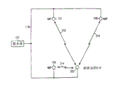
Fig. 2 illustrates the figure of the wireless network of the Network Access Point with new interpolation.Network 200 comprises server 122, medium 116 and Network Access Point 102,104,106 and 202.Network Access Point 202 is new Network Access Points that add.The new Network Access Point that adds is to still have Network Access Point to be configured.For example, can need " location " new Network Access Point that adds, thereby the Network Access Point of new interpolation is worked with other Network Access Point, to measure the position of the described various network elements of Fig. 1.The configuration of Network Access Point comprises many operations, and position finding is one of them.
Any Network Access Point that Network Access Point 202 expressions can be disposed.For example: Network Access Point 202 can be to have had a period of time in network, but the Network Access Point that was moved recently.When Network Access Point was moved, the access point that it can be used as new interpolation equally disposed.An operation to the Network Access Point that is moved recently is position finding.
Be in operation, the new Network Access Point 202 usefulness wireless signals that add are communicated by letter with 106 with NAP102,104 on Radio Link 212,214 and 216 respectively.In certain embodiments, during disposing, the new access point that adds 202 sends by NAP102,104 and 106 wireless signals that receive, and can measure the position of the access point 202 of new interpolation with the mode described in above Fig. 1.In other embodiments, the new access point that adds 202 receives wireless signals, measures their attribute and measures and position with respect to the access point 202 of the new interpolation of NAP102,104 and 106 position.
The position of the new access point that adds can be measured by server or by access point itself.For example: server 122 can be measured the position of the access point 202 of new interpolation, or the new access point 202 that adds can be measured the position of himself.In addition, can be in server, access point or multiple access point with the positional information memory.
Any amount of access point can be located with above-mentioned mode.For example: Network Access Point 102,104 and 106 can be determined as layoutprocedure a part.In certain embodiments, the position of any particular network access point is to measure when adding to Network Access Point in the network.In other embodiments, the position of Network Access Point is measured when wireless network access point.
As mentioned above, various embodiment of the present invention provides the position of the Network Access Point of new interpolation by the use known location of the access point in network.By the Network Access Point of the relevant new interpolation of self-align and existing access point, can simplify the process of the coverage rate that enlarges network 200 widely.When the new NAP that adds is installed, can measure them with respect to position at other access point of known and the position that records.
The position that other NAP in the scope of the new access point that adds can be used in certain embodiments, the new access point that adds.For example: " the some cloud " of coordinate that the various arrangements of the position NAP that set up can be used to provide the position of the new NAP that adds of sign.Statistical method can be used to improve the resolution and the accuracy of the measurement result of new NAP then.
Existing NAP can determine the position of the 4th the new NAP that adds and by acceptable calibration protocol these data be offered new NAP.This agreement can comprise to be used server 122 to carry out this calibration or only uses the direct reciprocation between the NAP they self to carry out this calibration.This agreement can be set up it is correlated with the coordinate system that the relevant network by existing NAP is formed or the relevant locus of absolute coordinate system in the inside of the new NAP that adds.The example of absolute coordinate system can comprise geographical coordinate, global positioning system (GPS) reference coordinate or building reference coordinate.Followingly the example of the network of location NAP in the different coordinates system is described with reference to Fig. 5 and Fig. 6.
Fig. 3 illustrates the figure that is suitable at the network insertion point device of Network Access Point use illustrated in figures 1 and 2.Network insertion point device 300 comprises transmitter 302, receiver 304, time of advent detector 306, angle of arrival detector 314, processor 308 and transceiver 310.Transceiver 310 is also communicated by letter with processor 308.Transmitter 302 is all communicated by letter with antenna 320 with processor 308 with receiver 304.
Can implement to arrive time detector 306 with some different modes.In one embodiment, the time of advent detector function be separate modules in the network insertion point device 300.In other embodiments, the time of advent, detector was integrated in the receiver 304.In further embodiments, the time of advent, detector 306 utilized the disposal ability of processor 308 to carry out its function.
Also can implement to arrive angle detector 314 with some different modes.In certain embodiments, angle of arrival detector is to receive from the signal of the phased array antenna circuit with the angle of measuring received signal.In these embodiments, antenna 320 can be represented phased array antenna.Many other mechanisms can be used to measure the angle of arrival of wireless signal.
When many network insertions point device 300 was measured the attribute of single electromagnetic pulse, the webserver can utilize this this information to decide the location of network nodes of sending pulse.Network insertion point device 300 can also directly utilize this information or utilize this information to decide the position of network insertion point device 300 with one or more access points.In certain embodiments, many electromagnetic pulses are received by receiver 304.Many electromagnetic pulses can represent any kind from network node or from the communication of another network insertion point device.For example: a set of pulses can be represented the request that special assets is positioned from network node.Again for example: a set of pulses can be illustrated in the calibrating sequence that is transmitted by the heterogeneous networks access device during the configuration sequence.Receiver 304 is from pulse group neutralization information extraction from the attribute of describing pulse.The information that the attribute that processor 308 receives paired pulses group and individual pulse from receiver 304 is described.For example: processor 308 can receive the data from network node, and receives the time of advent and the angle of arrival information of the pulse that is received by receiver 304.
Fig. 4 illustrates the figure of the webserver in the wireless network that is applicable to such as network 100 (Fig. 1) or network 200 (Fig. 2).Server 400 comprises processor 402, memory 404 and transceiver 406.Transceiver 406 is coupled at port one 16 and medium 108.As described above with reference to Figure 1, medium 108 are coupled the webserver and any amount of network insertion point device such as network insertion point device 300 (Fig. 3).Transceiver 406 is received in information on the medium 108 from network insertion point device 300 (Fig. 3).In certain embodiments, wireless signal attributes receives from many network insertions point device, and processor 402 is measured the position of the transmitter that sends wireless signal.Server 400 can be PC (PC), server, main frame, handheld device, portable computer or any other type can carry out operated system described here.
Fig. 5 is illustrated in first figure of the network insertion point device in the border.Shown in border 510 is NAP522,524 and 526.Network node 532,534 and 536 also is shown in border 510.Fig. 5 illustrates the method that each NAP locatees in various relative coordinate system.As shown in Figure 5, coordinate system is represented with border 510.The border or the coordinate system of any kind can be represented in border 510.For example: the border of building, geographical frontier or any kind can be represented in border 510.The coordinate system of any kind can also be represented in border 510.For example: geographical coordinate, global positioning system (GPS) reference coordinate or building reference coordinate can be represented in border 510.
Fig. 5 illustrates the method for the various relative coordinate location NAP of system.Here method shown in Figure 5 is called " key floorplan points methods ".In order to explain key floorplan points methods, suppose that the relative position of NAP is known in Fig. 5, but position the unknown of NAP retive boundary 510.When a NAP is placed on an optional position this situation can take place, then a plurality of other NAP are added into network and locate with respect to a NAP.
In key floorplan points methods, network node is placed on known " key " some place in the floor plan (or coordinate system), measures the position of network node with respect to NAP then.For example: as shown in Figure 5, network node 532 is placed on key point 512 places, and network node 534 is placed on key point 516 places, and network node 536 is placed on key point 514 places.In certain embodiments, the single network node is shifted to key point from key point, rather than places a node that separates at every turn.For example: the single network node can be placed on key point 512 and location, then it be shifted to key point 514 and location, then it be shifted to key point 516 and location.
Can be manually or automatically to the network identity key point.For example: can have the physical location of the key point of input by hand with the server (not shown) of NAP coupling.When network node being placed on key point and having measured them and during the relative position of NAP, server can calculate any scale, suitably NAP is placed in the coordinate system by border 510 expressions.
Fig. 6 is illustrated in second figure that is placed on Network Access Point in the border.Shown in border 510 is NAP610 and 612.Network node 614,616 and 618 also is shown in border 510.Fig. 6 illustrates the method that each NAP locatees in various relative coordinate system.As shown in Figure 6, coordinate system is represented with border 510.The border or the coordinate system of any kind can be represented in border 510.For example: the border of building, geographical frontier or any other type can be represented in border 510.The coordinate system of any kind can also be represented in border 510.For example: geographical coordinate, global positioning system (GPS) reference coordinate or building reference coordinate can be represented in border 510.
Fig. 6 illustrates various methods with respect to coordinate system location NAP.Here method shown in Figure 6 is called " known distance methods ".In order to explain key floorplan points methods, suppose that the relative position of NAP is known in Fig. 6, and NAP is with respect to the position the unknown on border 510.When a NAP is placed on an optional position this situation can take place, then NAP is added into network and locatees with respect to a NAP.
In known distance methods, the apart known distance of network node is placed in the border 510, measure the position of network node then with respect to NAP.For example: as shown in Figure 6, network node 614,616 apart distances 624 are placed, and network node 616,618 apart distances 622 are placed.Here the point that will place network node is called " shift position ".In certain embodiments, the single network node is shifted to another shift position from a shift position, rather than places an individual node at every turn.For example: as shown in Figure 6, the single network node can move between the shift position of node 614,616 and 618.
Can be manually or automatically to the network identity shift position.For example: can have the physical location of the shift position of manual input with the server (not shown) of NAP coupling.When network node being placed on the shift position and having measured them and during the relative position of NAP, server can calculate any scale, suitably NAP is placed in the coordinate system by border 510 expressions.
Fig. 7, Fig. 8 and Fig. 9 illustrate flow chart according to various embodiments of the present invention.The flow chart of Fig. 7, Fig. 8 and Fig. 9 illustrates the whole bag of tricks embodiment that can carry out in network.In certain embodiments, this method can be passed through the server such as server 122 (Fig. 1 and 2), or the network insertion node by the Network Access Point shown in Fig. 1,2,4,5 and 6 is carried out.In other embodiments, can stride one or more servers and one or more network insertion point device distributes this method.Exercises shown in the figure can be carried out with the order that presents, and also can carry out with different order.In addition, in certain embodiments, omitted some listed among figure action.
Now referring to Fig. 7, method 700 is since 710 places, receives wireless signal based on pulse at 710 place's wireless network access point equipment from a plurality of known location.In certain embodiments, these can be corresponding to the new NAP that adds from a plurality of NAP received signals network.For example: when the NAP202 of new interpolation (Fig. 2) receives wireless signal based on pulse on Radio Link 212,214 and 216, the action at 710 places can take place.
At 720 places, measure the time of advent of pulse.This can use the detector time of advent such as time of advent detector 306 (Fig. 3) to measure the time of advent corresponding to NAP202.At 730 places, measured the distance between a plurality of known location and the wireless network access point equipment.Can measure described distance by the time of more exomonental time and received pulse.At 740 places, from the position of range determination WAP (wireless access point).In certain embodiments, carrying out trigonometric calculations locates.
After 740, the position of wireless network access point is known.When wireless network access point is the NAP of new interpolation, this NAP can be used to help to locate the NAP of other new interpolation.At 750 places, measure and whether located more radio reception device.If like this, to each the wireless access point device repetition methods 700 that will locate.If not, then method 700 finishes.
In certain embodiments, statistical method also is used for the wireless network access point equipment described in the method 700 is carried out more accurate localization.For example: can repeatedly repeat action listed in 710,720,730 and 740 to each wireless network access point equipment, to set up " the some cloud " of the position of operation statistically, to increase the accuracy of location wireless network access point equipment.
Referring to Fig. 8, method 800 is from receiving from the wireless signal of first wireless network access point equipment emission at a plurality of different wireless network access point equipment.In certain embodiments, this can be sent to a plurality of NAP in network with signal corresponding to the new NAP that adds.For example: when the NAP of new interpolation (Fig. 2) is sent to wireless signal NAP102, the action at 810 places can takes place 104 and 106 the time on Radio Link 212,214 and 216.
At 820 places, measure the distance between the first wireless network access point equipment and a plurality of different wireless network access point.Can measure these distances by the time of more exomonental time and received pulse.At 830 places, from the position of range determination first wireless network access point.In certain embodiments, carrying out trigonometric calculations locates.
After 830, the position of first wireless network access point is known.When first wireless network access point is the NAP of new interpolation, this NAP can be used to help to locate the NAP of other new interpolation.Action in the method 800 can be repeated repeatedly, to locate a plurality of wireless network access point equipment.In addition, in certain embodiments, statistical method also is used for the wireless network access point equipment described in the method 800 is carried out more accurate localization.For example: can repeatedly repeat action listed in 810,820,830 and 840 to each wireless network access point equipment, to set up " the some cloud " of the position of operation statistically, to increase the accuracy of location wireless network access point equipment.
Now referring to Fig. 9, method 900 is sent to location-aware network since 910 places with wireless signal.This can be sent to location-aware network with signal corresponding to aforementioned NAP.For example: the action in 910 can be sent to NAP102,104 and 106 with signal corresponding to NAP202.
At 920 places, the information of describing the position of wireless network access device receives from location-aware network.In certain embodiments, this receives the information of describing its position corresponding to wireless network access point equipment from network.Can receive this information at Radio Link or on other medium outside the Radio Link.For example: referring to Fig. 2, when wireless network access point equipment is the new NAP202 that adds, this information can any Radio Link 212,214 216 or medium 116 on receive.At 930 places, the information stores of the position of description wireless network access device is in memory.Memory can be in wireless access point device, or other place in the network.For example: the new wireless network access point equipment 202 that adds can comprise the memory devices of having stored this information, or can comprise the server of the memory of having stored this information such as server 122.
Should understand above-mentioned explanation and be intended to example, and non-limiting.Read and understood above-mentioned explanation after many other embodiment will be conspicuous to one skilled in the art.Therefore, should determine scope of the present invention with reference to the claims and the gamut of the equivalent of these claims requirements.
Claims (9)
1. a method of measuring the position of access point apparatus in the wireless network is characterized in that, comprising:
Receive from the wireless signal of at least three known location emissions at a wireless network access point equipment place, wherein reflector is shifted to described at least three known location with the emission wireless signal;
Measure the distance between each of described at least three known location and described wireless network access point equipment according to the wireless signal that received; With
Find the solution the position of wireless network access point equipment by the distance of being measured.
2. the method for claim 1 is characterized in that, receives wireless signal and comprises the reception electromagnetic pulse.
3. method as claimed in claim 2 is characterized in that, describedly measures the time of advent that distance comprises the pulse that measurement receives at wireless network access point equipment.
4. method as claimed in claim 2 is characterized in that, describedly measures the angle of arrival that distance comprises the pulse that measurement receives at wireless network access point equipment.
5. the method for claim 1 is characterized in that, also comprises in a plurality of wireless network access point equipment each is repeated listed action.
6. the method for claim 1 is characterized in that, also comprises:
Repeatedly repeat described reception, mensuration and solution procedure, to obtain a plurality of values in position of wireless network access point equipment; With
The end value of described a plurality of values with the position of acquisition wireless network access point equipment handled on statistics ground.
7. the method for claim 1 is characterized in that, described at least three known location are corresponding to the known location in building.
8. the method for claim 1 is characterized in that, described at least three known location are corresponding to known geographical locations.
9. the method for claim 1 is characterized in that, described at least three known location are corresponding to a plurality of other wireless network access point equipment.
Applications Claiming Priority (2)
| Application Number | Priority Date | Filing Date | Title |
|---|---|---|---|
| US10/178,871 | 2002-06-24 | ||
| US10/178,871 US6956527B2 (en) | 2002-06-24 | 2002-06-24 | Wireless network access point configuration |
Publications (2)
| Publication Number | Publication Date |
|---|---|
| CN1663315A CN1663315A (en) | 2005-08-31 |
| CN100418328C true CN100418328C (en) | 2008-09-10 |
Family
ID=29734800
Family Applications (1)
| Application Number | Title | Priority Date | Filing Date |
|---|---|---|---|
| CNB038147505A Expired - Fee Related CN100418328C (en) | 2002-06-24 | 2003-06-19 | Wireless network access point configuration |
Country Status (8)
| Country | Link |
|---|---|
| US (1) | US6956527B2 (en) |
| EP (1) | EP1525770B1 (en) |
| CN (1) | CN100418328C (en) |
| AT (1) | ATE440475T1 (en) |
| AU (1) | AU2003245540A1 (en) |
| DE (1) | DE60328896D1 (en) |
| MY (1) | MY134354A (en) |
| WO (1) | WO2004002185A1 (en) |
Families Citing this family (63)
| Publication number | Priority date | Publication date | Assignee | Title |
|---|---|---|---|---|
| US20040203873A1 (en) * | 2002-09-19 | 2004-10-14 | William H. Gray | Method and system of informing WAN user of nearby WLAN access point |
| US7116993B2 (en) * | 2002-09-27 | 2006-10-03 | Rockwell Automation Technologies, Inc. | System and method for providing location based information |
| US8156539B1 (en) * | 2002-12-18 | 2012-04-10 | Cypress Semiconductor Corporation | Method and system for protecting a wireless network |
| US7162252B2 (en) * | 2002-12-23 | 2007-01-09 | Andrew Corporation | Method and apparatus for supporting multiple wireless carrier mobile station location requirements with a common network overlay location system |
| US7272456B2 (en) | 2003-01-24 | 2007-09-18 | Rockwell Automation Technologies, Inc. | Position based machine control in an industrial automation environment |
| US8483717B2 (en) | 2003-06-27 | 2013-07-09 | Qualcomm Incorporated | Local area network assisted positioning |
| US8971913B2 (en) | 2003-06-27 | 2015-03-03 | Qualcomm Incorporated | Method and apparatus for wireless network hybrid positioning |
| US20050070304A1 (en) * | 2003-09-30 | 2005-03-31 | Farchmin David W. | Distributed wireless positioning engine method and assembly |
| GB0324098D0 (en) | 2003-10-15 | 2003-11-19 | Koninkl Philips Electronics Nv | Method and apparatus for indicating the location of an object |
| KR20060133972A (en) * | 2003-11-05 | 2006-12-27 | 코닌클리케 필립스 일렉트로닉스 엔.브이. | Different permissions for a control point in a media provision entity |
| US20050124355A1 (en) * | 2003-12-04 | 2005-06-09 | International Business Machines Corporation | Self-directed access point location validation |
| US8645569B2 (en) | 2004-03-12 | 2014-02-04 | Rockwell Automation Technologies, Inc. | Juxtaposition based machine addressing |
| US7152791B2 (en) * | 2004-03-30 | 2006-12-26 | Honeywell International, Inc. | Identifying the location of an asset |
| US7319878B2 (en) | 2004-06-18 | 2008-01-15 | Qualcomm Incorporated | Method and apparatus for determining location of a base station using a plurality of mobile stations in a wireless mobile network |
| US7403762B2 (en) | 2004-10-29 | 2008-07-22 | Skyhook Wireless, Inc. | Method and system for building a location beacon database |
| US8369264B2 (en) | 2005-10-28 | 2013-02-05 | Skyhook Wireless, Inc. | Method and system for selecting and providing a relevant subset of Wi-Fi location information to a mobile client device so the client device may estimate its position with efficient utilization of resources |
| US7542572B2 (en) * | 2004-12-01 | 2009-06-02 | Cisco Technology, Inc. | Method for securely and automatically configuring access points |
| BRPI0606899A2 (en) * | 2005-02-10 | 2010-01-26 | Stephan Daniul Britz | object monitoring system and method |
| KR101249178B1 (en) | 2005-02-22 | 2013-04-03 | 스카이후크 와이어리스, 인크. | Continuous data optimization in positioning system |
| US20090055541A1 (en) * | 2005-03-22 | 2009-02-26 | Nec Corporation | Connection parameter setting system, method thereof, access point, server, wireless terminal, and parameter setting apparatus |
| US7710322B1 (en) | 2005-05-10 | 2010-05-04 | Multispectral Solutions, Inc. | Extensible object location system and method using multiple references |
| EP1739881A1 (en) * | 2005-06-30 | 2007-01-03 | Alcatel | Determination of the position of a base station and then of a terminal in a wireless lan |
| US8169982B2 (en) | 2005-08-10 | 2012-05-01 | Qualcomm Incorporated | Method and apparatus for creating a fingerprint for a wireless network |
| US7257413B2 (en) * | 2005-08-24 | 2007-08-14 | Qualcomm Incorporated | Dynamic location almanac for wireless base stations |
| CN106054129A (en) * | 2005-11-07 | 2016-10-26 | 高通股份有限公司 | Positioning for wlans and other wireless networks |
| RU2390791C2 (en) | 2005-11-07 | 2010-05-27 | Квэлкомм Инкорпорейтед | Positioning for wlan and other wireless networks |
| US8144673B2 (en) | 2006-07-07 | 2012-03-27 | Skyhook Wireless, Inc. | Method and system for employing a dedicated device for position estimation by a WLAN positioning system |
| US7589671B2 (en) * | 2006-08-25 | 2009-09-15 | Trimble Navigation Limited | GPS node locator using an intermediate node location for determining location of a remote node |
| US20080068262A1 (en) * | 2006-08-25 | 2008-03-20 | Peter Van Wyck Loomis | Remote node providing GPS signal samples for GPS positioning over a communication network |
| US8320331B2 (en) | 2006-10-27 | 2012-11-27 | Telefonaktiebolaget Lm Ericsson (Publ) | Method and apparatus for estimating a position of an access point in a wireless communications network |
| US9226257B2 (en) | 2006-11-04 | 2015-12-29 | Qualcomm Incorporated | Positioning for WLANs and other wireless networks |
| US7551126B2 (en) * | 2007-03-08 | 2009-06-23 | Trimble Navigation Limited | GNSS sample processor for determining the location of an event |
| US7719467B2 (en) | 2007-03-08 | 2010-05-18 | Trimble Navigation Limited | Digital camera with GNSS picture location determination |
| US7684370B2 (en) * | 2007-05-03 | 2010-03-23 | Research In Motion Limited | Adaptive beamforming configuration methods and apparatus for wireless access points serving as handoff indication mechanisms in wireless local area networks |
| US8391487B2 (en) | 2007-07-24 | 2013-03-05 | Cisco Technology, Inc. | Secure remote configuration of device capabilities |
| US9137745B2 (en) * | 2007-10-12 | 2015-09-15 | Qualcomm Incorporated | System and method to locate femto cells with passive assistance from a macro cellular wireless network |
| US9253653B2 (en) * | 2007-11-09 | 2016-02-02 | Qualcomm Incorporated | Access point configuration based on received access point signals |
| KR100946984B1 (en) * | 2007-12-10 | 2010-03-10 | 한국전자통신연구원 | System and method for chasing location |
| US8897801B2 (en) | 2008-06-13 | 2014-11-25 | Qualcomm Incorporated | Transmission of location information by a transmitter as an aid to location services |
| US8155666B2 (en) | 2008-06-16 | 2012-04-10 | Skyhook Wireless, Inc. | Methods and systems for determining location using a cellular and WLAN positioning system by selecting the best cellular positioning system solution |
| DE102009025851A1 (en) * | 2009-05-20 | 2010-11-25 | Deutsche Telekom Ag | Method for determining the location of a femtocell |
| US8838096B2 (en) * | 2009-05-29 | 2014-09-16 | Qualcomm Incorporated | Non-macro cell search integrated with macro-cellular RF carrier monitoring |
| US8406785B2 (en) | 2009-08-18 | 2013-03-26 | Skyhook Wireless, Inc. | Method and system for estimating range of mobile device to wireless installation |
| US20110134833A1 (en) * | 2009-12-08 | 2011-06-09 | Qualcomm Incorporated | Controlling access point functionality |
| FR2954631B1 (en) * | 2009-12-21 | 2012-08-10 | Canon Kk | METHOD AND APPARATUS FOR CLOSED LOOP CONFIGURATION OF ANTENNA NETWORK |
| US9253605B2 (en) | 2010-03-24 | 2016-02-02 | Skyhook Wireless, Inc. | System and method for resolving multiple location estimate conflicts in a WLAN-positioning system |
| US8923892B2 (en) | 2010-05-14 | 2014-12-30 | Qualcomm Incorporated | Method and apparatus for updating femtocell proximity information |
| CN102279382A (en) * | 2010-06-09 | 2011-12-14 | 日电(中国)有限公司 | Receiver system, arrangement method thereof and positioning system comprising receiver system |
| EP2580605B1 (en) | 2010-06-11 | 2016-05-04 | Skyhook Wireless, Inc. | Methods of and systems for measuring beacon stability of wireless access points |
| WO2012035435A1 (en) | 2010-09-13 | 2012-03-22 | Marvell World Trade Ltd. | Adjusting transmission rate and range of a wireless access point |
| US8606294B2 (en) | 2010-10-05 | 2013-12-10 | Skyhook Wireless, Inc. | Method of and system for estimating temporal demographics of mobile users |
| EP2635915B1 (en) | 2010-11-03 | 2016-05-18 | Skyhook Wireless, Inc. | Method of system for increasing the reliability and accuracy of location estimation in a hybrid positioning system |
| US20120150573A1 (en) * | 2010-12-13 | 2012-06-14 | Omar Soubra | Real-time site monitoring design |
| US8582422B2 (en) | 2011-04-05 | 2013-11-12 | Hewlett-Packard Development Company, L.P. | Access point configuration propagation |
| US20120331561A1 (en) | 2011-06-22 | 2012-12-27 | Broadstone Andrew J | Method of and Systems for Privacy Preserving Mobile Demographic Measurement of Individuals, Groups and Locations Over Time and Space |
| US9282433B2 (en) * | 2012-12-12 | 2016-03-08 | Qualcomm Incorporated | System and/or method of locating a portable service access transceiver |
| KR101867745B1 (en) | 2014-03-28 | 2018-06-14 | 인텔 아이피 코포레이션 | Method and apparatus for wi-fi location determination |
| CN114189857B (en) * | 2017-05-11 | 2023-11-28 | 无线通信与技术公司 | Gateway and method implemented by gateway |
| CN107548028A (en) * | 2017-08-02 | 2018-01-05 | 福州市协成智慧科技有限公司 | A kind of indoor occupant motion track computing system and method |
| US10470052B2 (en) * | 2017-11-13 | 2019-11-05 | Common Networks, Inc. | Systems and methods for configuring radio communication devices |
| US11483678B2 (en) | 2018-05-23 | 2022-10-25 | Delaval Holding Ab | System, method and computer program for positioning animal tags |
| US11743738B2 (en) | 2020-03-05 | 2023-08-29 | Comcast Cable Communications, Llc | Evaluation of access point placement |
| US20210385623A1 (en) * | 2020-06-09 | 2021-12-09 | WiTagg, Inc. | Devices, systems and methods for detecting locations of wireless communication devices |
Citations (7)
| Publication number | Priority date | Publication date | Assignee | Title |
|---|---|---|---|---|
| US5515062A (en) * | 1993-08-11 | 1996-05-07 | Motorola, Inc. | Location system and method with acquisition of accurate location parameters |
| US5883598A (en) * | 1995-12-15 | 1999-03-16 | Signatron Technology Corporation | Position location system and method |
| CN1254484A (en) * | 1997-05-09 | 2000-05-24 | 诺基亚网络有限公司 | A method for determining timing differences between radio transmitters and radio network incorporating the same |
| CN1269082A (en) * | 1997-07-15 | 2000-10-04 | 全点有限公司 | Mobile station locating system and method |
| US6249252B1 (en) * | 1996-09-09 | 2001-06-19 | Tracbeam Llc | Wireless location using multiple location estimators |
| WO2001078326A2 (en) * | 2000-04-10 | 2001-10-18 | Carnegie Mellon University | Method for configuring and assigning channels for a wireless network |
| WO2002035766A2 (en) * | 2000-10-23 | 2002-05-02 | Wayport, Inc. | Wireless telecommunications system that provides location-based services |
Family Cites Families (14)
| Publication number | Priority date | Publication date | Assignee | Title |
|---|---|---|---|---|
| US5677927A (en) | 1994-09-20 | 1997-10-14 | Pulson Communications Corporation | Ultrawide-band communication system and method |
| US6026304A (en) * | 1997-01-08 | 2000-02-15 | U.S. Wireless Corporation | Radio transmitter location finding for wireless communication network services and management |
| WO1998052376A1 (en) | 1997-05-09 | 1998-11-19 | Nokia Telecommunications Oy | A method for determining timing differences between radio transmitters and a radio network incorporating the same |
| US6442507B1 (en) * | 1998-12-29 | 2002-08-27 | Wireless Communications, Inc. | System for creating a computer model and measurement database of a wireless communication network |
| US6295022B1 (en) * | 1999-05-25 | 2001-09-25 | Raytheon Company | Apparatus and method for determination of a receiver position |
| US6529164B1 (en) * | 2000-03-31 | 2003-03-04 | Ge Medical Systems Information Technologies, Inc. | Object location monitoring within buildings |
| US7072650B2 (en) * | 2000-11-13 | 2006-07-04 | Meshnetworks, Inc. | Ad hoc peer-to-peer mobile radio access system interfaced to the PSTN and cellular networks |
| US7046657B2 (en) * | 2000-12-20 | 2006-05-16 | Wherenet Corp | Wireless local area network system with mobile access point station determination |
| US6473038B2 (en) * | 2001-01-05 | 2002-10-29 | Motorola, Inc. | Method and apparatus for location estimation |
| US6618005B2 (en) * | 2001-06-29 | 2003-09-09 | Intel Corporation | Determining wireless device locations |
| ATE365337T1 (en) * | 2001-09-05 | 2007-07-15 | Newbury Networks Inc | POSITION DETECTION AND LOCATION TRACKING IN A WIRELESS NETWORK |
| US6664925B1 (en) * | 2002-05-02 | 2003-12-16 | Microsoft Corporation | Method and system for determining the location of a mobile computer |
| US7711375B2 (en) * | 2002-08-06 | 2010-05-04 | Hang Liu | Method and system for determining a location of a wireless transmitting device and guiding the search for the same |
| WO2004105356A2 (en) * | 2003-05-19 | 2004-12-02 | Board Of Control Of Michigan Technological University | Wireless local positioning system |
-
2002
- 2002-06-24 US US10/178,871 patent/US6956527B2/en not_active Expired - Lifetime
-
2003
- 2003-06-19 WO PCT/US2003/019094 patent/WO2004002185A1/en not_active Application Discontinuation
- 2003-06-19 DE DE60328896T patent/DE60328896D1/en not_active Expired - Lifetime
- 2003-06-19 AU AU2003245540A patent/AU2003245540A1/en not_active Abandoned
- 2003-06-19 AT AT03739165T patent/ATE440475T1/en not_active IP Right Cessation
- 2003-06-19 EP EP03739165A patent/EP1525770B1/en not_active Expired - Lifetime
- 2003-06-19 CN CNB038147505A patent/CN100418328C/en not_active Expired - Fee Related
- 2003-06-23 MY MYPI20032331A patent/MY134354A/en unknown
Patent Citations (8)
| Publication number | Priority date | Publication date | Assignee | Title |
|---|---|---|---|---|
| US5515062A (en) * | 1993-08-11 | 1996-05-07 | Motorola, Inc. | Location system and method with acquisition of accurate location parameters |
| US5883598A (en) * | 1995-12-15 | 1999-03-16 | Signatron Technology Corporation | Position location system and method |
| US6249252B1 (en) * | 1996-09-09 | 2001-06-19 | Tracbeam Llc | Wireless location using multiple location estimators |
| CN1254484A (en) * | 1997-05-09 | 2000-05-24 | 诺基亚网络有限公司 | A method for determining timing differences between radio transmitters and radio network incorporating the same |
| CN1269082A (en) * | 1997-07-15 | 2000-10-04 | 全点有限公司 | Mobile station locating system and method |
| US6308073B1 (en) * | 1997-07-15 | 2001-10-23 | Xircom Wireless, Inc. | Mobile station locating and tracking system and method |
| WO2001078326A2 (en) * | 2000-04-10 | 2001-10-18 | Carnegie Mellon University | Method for configuring and assigning channels for a wireless network |
| WO2002035766A2 (en) * | 2000-10-23 | 2002-05-02 | Wayport, Inc. | Wireless telecommunications system that provides location-based services |
Also Published As
| Publication number | Publication date |
|---|---|
| WO2004002185A1 (en) | 2003-12-31 |
| CN1663315A (en) | 2005-08-31 |
| DE60328896D1 (en) | 2009-10-01 |
| US20030234741A1 (en) | 2003-12-25 |
| EP1525770B1 (en) | 2009-08-19 |
| EP1525770A1 (en) | 2005-04-27 |
| MY134354A (en) | 2007-12-31 |
| AU2003245540A1 (en) | 2004-01-06 |
| ATE440475T1 (en) | 2009-09-15 |
| US6956527B2 (en) | 2005-10-18 |
Similar Documents
| Publication | Publication Date | Title |
|---|---|---|
| CN100418328C (en) | Wireless network access point configuration | |
| US20030235172A1 (en) | Asset tracking methods and apparatus | |
| Priyantha et al. | The cricket location-support system | |
| CN111868546B (en) | Asset localization using direction finding features | |
| US7899006B2 (en) | Location system for wireless local area network (WLAN) using RSSI and time difference of arrival (TDOA) processing | |
| US7411551B2 (en) | System and method for asynchronous wireless positioning by ordered transmission | |
| Liu et al. | Survey of wireless indoor positioning techniques and systems | |
| EP1172663A2 (en) | System for wireless location and direction indication including multiple devices | |
| EP2975426A1 (en) | Monitoring the movement of mobile communication devices | |
| CN1663228B (en) | Call routing in a user location-aware network | |
| US20080182593A1 (en) | System and Method for Asset Location in Wireless Networks | |
| Rodriguez et al. | In-building location using bluetooth | |
| WO2005109030A1 (en) | Position estimation of transceivers in communication networks | |
| Muñoz-Organero et al. | Using bluetooth to implement a pervasive indoor positioning system with minimal requirements at the application level | |
| CN102016626A (en) | System and method of position location transfer | |
| US20130023283A1 (en) | System for Wireless Location Estimation Using Radio Transceivers with Polarization Diversity | |
| CN110572774B (en) | Indoor multi-base-station extension method based on UWB self-positioning | |
| Sichitiu et al. | Simple Algorithm for Outdoor Localization of Wireless Sensor Networks with Inaccurate Range Measurements. | |
| Doiphode et al. | Survey of indoor positioning measurements, methods and techniques | |
| Popa et al. | Combining cricket system and inertial navigation for indoor human tracking | |
| Agre et al. | A layered architecture for location-based services in wireless ad hoc networks | |
| Claro et al. | Local positioning system based on artificial neural networks | |
| Magedanz et al. | Grips generic radio based indoor positioning system | |
| Zhong et al. | Node localization in wireless sensor networks | |
| Navalho et al. | Collaborative cellular-based location system |
Legal Events
| Date | Code | Title | Description |
|---|---|---|---|
| C06 | Publication | ||
| PB01 | Publication | ||
| C10 | Entry into substantive examination | ||
| SE01 | Entry into force of request for substantive examination | ||
| C14 | Grant of patent or utility model | ||
| GR01 | Patent grant | ||
| C17 | Cessation of patent right | ||
| CF01 | Termination of patent right due to non-payment of annual fee |
Granted publication date: 20080910 Termination date: 20130619 |